Embed Size (px)
Citation preview
NEW HAMPSHIRE DEPARTMENT OF TRANSPORTATION
April 2004

NHDOT CAD/D Procedures and Requirements
April 2004 i Part I – General Introduction
PART I – GENERAL INTRODUCTION........................................................................... 1
DISCLAIMER .............................................................................................................................................................1
REVISION SUMMARY .............................................................................................................................................2 April 2004..................................................................................................................................................................2 April 2002..................................................................................................................................................................3
INTRODUCTION .......................................................................................................................................................4
CURRENT NHDOT SOFTWARE VERSIONS.......................................................................................................5 Major Software and Current Production Versions.....................................................................................................5 Future Upgrades ........................................................................................................................................................5
PART II – MICROSTATION............................................................................................ 7
File Naming ..................................................................................................................................................................7 Cut Sheets..................................................................................................................................................................7 Roll Plans...................................................................................................................................................................7
Level Assignments and Symbology ............................................................................................................................7
Seed Files ......................................................................................................................................................................8 Imperial 3D Seed File (NHSEEDFT.DGN) ..............................................................................................................9 Imperial 2D Seed File (NHSEEDF2.DGN)...............................................................................................................9 Metric 3D Seed File (NHSEEDM.DGN) ..................................................................................................................9 Metric 2D Seed File (NHSEEDM2.DGN) ................................................................................................................9
Reference File Attachments ........................................................................................................................................9
Directory Structure ...................................................................................................................................................10
Text Styles ..................................................................................................................................................................10
Text Size and Spacing................................................................................................................................................11 Standard Text Sizes .................................................................................................................................................11
Line Styles ..................................................................................................................................................................12 NHDOT Custom Line Style Resource Files............................................................................................................12 Custom Linestyle Scaling Charts.............................................................................................................................12
Notes ...........................................................................................................................................................................13
Color Table.................................................................................................................................................................14
Cell Files .....................................................................................................................................................................14
Dimensioning..............................................................................................................................................................15
Cross-Section Drawings ............................................................................................................................................15
Detail Sheets ...............................................................................................................................................................16
NHDOT CAD/D Procedures and Requirements
Table of Contents ii April 2004
Plotting .......................................................................................................................................................................16
Pen Tables ..................................................................................................................................................................17
BatchPlot ....................................................................................................................................................................17
PART III – MX ............................................................................................................... 19
File Naming ................................................................................................................................................................19
Model Naming............................................................................................................................................................19
String Labeling ..........................................................................................................................................................19
Style Sets.....................................................................................................................................................................20
Feature Sets................................................................................................................................................................20 NHDOT Developed Style sets for MX drawings ....................................................................................................20 Style sets and feature sets used to create MicroStation drawings............................................................................20
Drawing Macros ........................................................................................................................................................21
Cross-Section Settings Files ......................................................................................................................................21
Macro Symbols & Lines............................................................................................................................................21
PART IV – OTHER PROJECT DATA........................................................................... 23
Project Journal Files .................................................................................................................................................23 Project Journal Guidelines.......................................................................................................................................23 Example of CAD/D Project Journal ........................................................................................................................24
Drawing Quality Assurance / Quality Control........................................................................................................27 QA_Input.................................................................................................................................................................27 QuikChek.................................................................................................................................................................27 Spot_Fix ..................................................................................................................................................................27
PART V – ENGINEERING CONSULTANT REQUIREMENTS..................................... 29
Overview.....................................................................................................................................................................29
FILE FORMAT AND DELIVERY..........................................................................................................................29 Requirements For Submitting Electronic Data To NHDOT....................................................................................29 Data Submission......................................................................................................................................................29 Deviation From Format ...........................................................................................................................................30 MicroStation Only Deliverable................................................................................................................................30 MicroStation Plot Files (Final Design Consultants Only) .......................................................................................30 File Conversion........................................................................................................................................................31
NHDOT Design Process ............................................................................................................................................31 Plan Preparation.......................................................................................................................................................31 Preliminary Design ..................................................................................................................................................32 Final Design.............................................................................................................................................................33
NHDOT CAD/D Procedures and Requirements
April 2004 iii Part I – General Introduction
Projects Designed Using InRoads/SelectCAD ........................................................................................................33 Specialized Development by Design Consultants ...................................................................................................34
NHDOT Resources Available for Consultants........................................................................................................34
PART VI - APPENDIX................................................................................................... 35
Appendix A - MicroStation Drawing Names...........................................................................................................35 Highway Design Drawings......................................................................................................................................35 Cut Sheet Drawing Types........................................................................................................................................35 BRIDGE DESIGN DRAWINGS ............................................................................................................................36
Appendix B - Level Mapping Convention ...............................................................................................................37
Appendix C - NHDOT Custom Linestyles ..............................................................................................................38
Appendix D – MX Model Naming Convention .......................................................................................................41 Plan Preparation Models..........................................................................................................................................41 Preliminary Design Models .....................................................................................................................................42 Final Design Models................................................................................................................................................43
Appendix E – MX Detail String Labeling Convention (Topical) ..........................................................................45
Appendix F – MX Detail String Labeling Convention (Alphabetical)..................................................................51
Appendix G – MX Design String Labeling Convention .........................................................................................57
Appendix H – MX Alignment Data Formats (HALGN & VERAT) .....................................................................59 HALGN ...................................................................................................................................................................59 VERAT....................................................................................................................................................................61
Appendix I – Construction Reports ........................................................................................................................63 Sample Alignment Report (COGO Style) ...............................................................................................................63 Sample Alignment Report (Coordinates) ................................................................................................................64

April 2004
PART I – GENERAL INTRODUCTION
DISCLAIMER
The procedures described in this document are for reference only. The material contained is provided without warranty or liability of any kind to the New Hampshire Department of Transportation. Every effort has been made to make the documentation as complete and accurate as possible without errors. This information is provided on an "as is" basis. Updates to these procedures and requirement will be made as needed due to any errors found in the documentation, new programs, change in software, software enhancements, or as policy and management dictate. As with any documentation, improvements can and should be made. Any additions, suggestions or comments for improvement are encouraged. This documentation is not meant to be a complete instructional document. The intent is to provide guidelines that, if followed, will result in better quality and consistency for electronic plans and documents. Current versions of software specific files (style libraries, fonts, naming conventions, etc.) can be found on the NHDOT CAD/D website at http://www.state.nh.us/dot/its/cadd/cadd.html Any recommendation for improvement to this documentation is welcome. Any errors found should be brought to the attention of NHDOT so corrections can be made. Any additional information or detailed explanation needed should be documented and mailed to: CAD/D Support and Development
New Hampshire Department of Transportation PO Box 483 Concord, NH 03302-0483 E-mail: [email protected]
Tel: 603-271-2171
NHDOT CAD/D Procedures and Requirements
Part I – General Introduction 2 April 2004
REVISION SUMMARY
APRIL 2004 General Part II – MicroStation
• References to MicroStation/J features have been modified to reflect the upgrade to MicroStation v8. • References to Settings Manager have been removed. • Corrected errors in custom linestyle scaling charts. • New cell files added. These are identified within the text.
Part III – MX
• Style sets have been updated for MX 2.6/MicroStation v8. Appendix
• References to MX version 2.5 have been modified to reflect the upgrade to MX 2.6 • Modifications have been made to the MicroStation drawing name list. Specific changes are identified in
the drawing list. • Some MX string labels have been added or modified. These are identified within the string label tables.
NHDOT CAD/D Procedures and Requirements
April 2004 3 Part I – General Introduction
APRIL 2002 General Consultant deliverable specifications relocated from various parts of the document and combined as Part V – Engineering Consultant Requirements Part II – MicroStation
• The process for creating cut sheets has been modified along with the sheet naming convention. • The project directory structure was modified to include subdirectories for front sheets and profiles. The
bridge directory now includes additional subdirectories. • Changes to cell file listing – titles.cel was renamed to stamps.cel, borders.cel, br_borders.cel, stnoffset.cel,
and turnrad.cel have been added. • Information about the NHDOT pen table has been included. • BatchPlot information has been added.
Part III – MX
• Additional style sets have been listed. Part IV – Other Project Data
• Information about the quality assurance/quality control software has been included. Part V – Engineering Consultant Requirements
• New section. • NHDOT will only accept plan drawings that were developed in MicroStation for projects that were initiated
after April 18, 2002. • MicroStation plot file returnable changed from HPGL to PDF format.
Appendix
• Modifications have been made to the MicroStation drawing name list. Specific changes are identified in the drawing list.
• Information about MicroStation level colors, styles, and cell names have been removed to avoid potential conflicts with documentation on the CAD/D website.
• Some MX string labels have been added or modified. These are identified with the string label tables.
NHDOT CAD/D Procedures and Requirements
Part I – General Introduction 4 April 2004
INTRODUCTION
This document is the New Hampshire Department of Transportation’s (NHDOT) specifications for required electronic (computer) data as it relates to engineering design project deliverables. In addition to the traditional hardcopy delivery items, NHDOT requires supplementary electronic data delivery items. This data shall be submitted in the formats specified by this document. In general, design data and Digital Terrain Model (DTM) data is to be provided in the MX model file or 3-D DXF file formats, and graphical data is to be provided in MicroStation's .DGN drawing format. Organizations wishing to perform professional engineering services for NHDOT are required to deliver electronic data as specified by this document. This specification also requires organizations to accept and utilize pertinent electronic input data as provided by NHDOT. These electronic delivery items DO NOT replace any hardcopy delivery items. The requirements in this document represent the minimum requirements that must be met for the development of NHDOT Computer Aided Design & Drafting (CAD/D) projects. While the requirements contained herein provide a basis for uniform CAD/D practice for NHDOT projects, precise rules that would apply to all possible situations that may arise are not possible to describe. Situations may exist where these standards will not apply. If variances from the NHDOT CAD/D Procedures and Requirements are necessary for a project, they must be approved in writing by the NHDOT Project Manager and documented in the Project Journal File as defined herein. Engineering projects are expected to adhere to the standards that were in force at the time the contract was initiated. Consultants may voluntarily choose to follow a later revision. This document is published as a complete revision to the "CAD/D PROCEDURES AND REQUIREMENTS" document dated April 2002. Trademarks
GEOPAK is a registered trademark of GEOPAK Corporation. Microsoft, Windows and Windows NT are registered trademarks of Microsoft Corporation. MicroStation, MDL, InRoads, MX, MXROAD and SelectCAD are registered trademarks of Bentley Systems, Inc.
NHDOT CAD/D Procedures and Requirements
April 2004 5 Part I – General Introduction
CURRENT NHDOT SOFTWARE VERSIONS
NHDOT desires to stay current with state of the art trends in the market, however, budget constraints, statewide implementation, impact on users, and providing support for the new features must be considered prior to any change. As NHDOT makes a change that results in modifying electronic procedures, the CAD/D Procedures and Requirements will be updated where necessary to reflect the change. A list of the modifications will be found in the revision summary. As a rule, until documentation is modified, no deviation from the current dated requirements should be considered.
MAJOR SOFTWARE AND CURRENT PRODUCTION VERSIONS
1. MicroStation v8 version 08.01.02.15 2. MX version 2.6.3 3. Microsoft Office 2000 products with Excel 2002
FUTURE UPGRADES
As this document is being written, new versions of MicroStation and MX are being released. The impact, if any, caused by the release of version 8.5 is not yet known.

NHDOT CAD/D Procedures and Requirements
April 2004 7 Part II - MicroStation
PART II – MICROSTATION
FILE NAMING
An attempt shall be made to have electronic files named using only an eight character file name with a .DGN extension. However, it is understood that this will not always be possible or preferable. Only alpha or numeric characters with no spaces or special characters shall be used.
CUT SHEETS
Project sheet file names are composed of four parts; the NHDOT state project number (first five fields), drawing type, sheet number (usually the last two fields), and the file extension. The five digit project number is assigned by NHDOT. The letter(s) following the project number indicate the type of cut sheet drawing. The sheet number is a sequential listing of the type of cut sheet for the project. (Ex. 12345R01 : “12345” - project number, “R” – ROW, “01” – ROW Cut Sheet 1.) The extension is always “.DGN”. Modifications to this format will be noted in the Project Journal File. A listing of drawing type designators used by NHDOT is contained in APPENDIX A - MICROSTATION DRAWING NAMES beginning on page 35. Realizing that there are a number of different ways to accomplish this same task, variations to the method described above may be acceptable with prior approval of NHDOT. Consultants wishing to use an alternative method should contact the project manager to arrange a meeting with the CAD/D development staff.
ROLL PLANS
Project “roll-plan” file names are composed of three parts; the NHDOT state project number (first five fields), drawing type (last three fields), and the .DGN file extension. A further explanation of standard naming conventions and drawing type designators used by NHDOT is contained in APPENDIX A - MICROSTATION DRAWING NAMES beginning on page 35.
LEVEL ASSIGNMENTS AND SYMBOLOGY
MicroStation v8 allows unlimited levels in each file. MicroStation/J level schemes have been modified to take advantage of the additional levels available in v8. Elements used to construct CAD/D drawings shall be placed on the appropriate design file levels. The level naming convention can be found on the NHDOT CAD/D website. Standard plan sheet symbols are illustrated in volume 2 of the NHDOT Design Manual on the Standard Symbol drawing. Line weights, styles and text height shall conform to the sample drawings shown in volume 2 of the NHDOT Design Manual. Use of NHDOT-defined MicroStation line styles is preferred. The consultant, with the approval

NHDOT CAD/D Procedures and Requirements
Part III - MicroStation 8 April 2004
of the Project Engineer, may create symbols that are not covered in the NHDOT Design Manual or contained in NHDOT cell libraries that are needed to complete project plans. Resource files containing any linestyles and/or symbols created by the consultant for use on the project drawings will be provided to NHDOT. Actual symbols for use with MicroStation software, including standard borders, are contained in NHDOT’s standard cell libraries and are available in MicroStation .CEL file format. A standard color table, standard metric & Imperial line style resource files with NHDOT line styles and font library with NHDOT fonts for use with MicroStation are available. This data is available on the NHDOT website or can be requested through the Project Manager. The website address is listed in the Disclaimer section at the beginning of this document. Level library files contain level names and color/weight/style information for MicroStation .DGNs. For Highway Design use there are level library files available for most detail drawings. These files have the same 3-character name as the drawing with an .CSV extension. For example, the level naming file for drawing 12345exd.dgn will be exd.csv. There are two .CSV files to be utilized when creating .DGNs for the Bureau of Bridge Design. The first file is called brc.csv, and stands for BRidge Cut-sheet. It contains the names required to accurately place graphical elements on a cut sheet (also referred to as a detail sheet). The second file, called brdcsvl, contains the names required to place graphical elements in a .DGN at project coordinates. Many of the names in brd.csv are required in order to transfer elements to MX For MicroStation. If information is not going to be passed from MicroStation into MX, several of the layers will remain vacant. Level standards for front sheets, right-of-way summaries, and property layout sheets is contained in bdr.csv. All the level files mentioned are available on the CAD/D website or can be requested through the Project Manager. The website address is listed in the Disclaimer section at the beginning of this document.
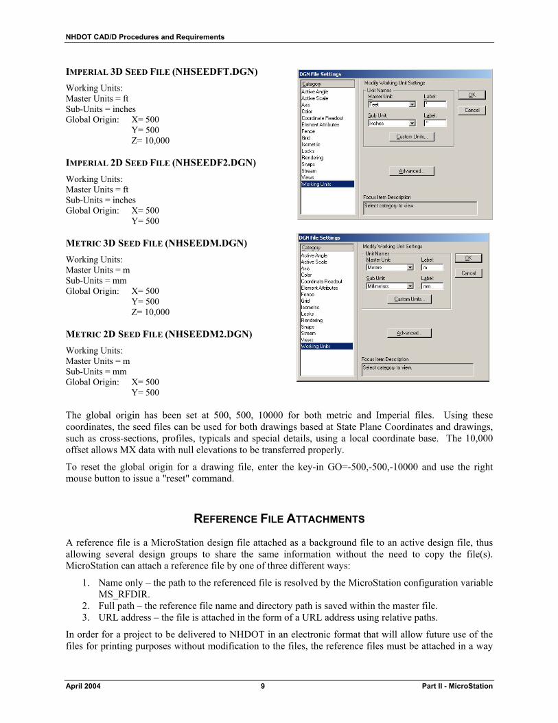
SEED FILES
MicroStation uses “seed” files to create all design files. These seed files are templates in which standard parameters are set according to what is needed to begin drafting for a specific type of work in accordance with NHDOT standards. The seed file defines the working units for the file, global origin, view attributes, default color table, text settings, coordinate readout and several other important parameters. NHDOT supplies seed files for both metric and Imperial drawings. Seed files allow the user to begin work in a standard format and maintain uniformity.
By default, NHDOT design teams are working with 2-D drawings. If a consultant prefers to use 3-D drawings, this should be mentioned prior to obtaining design data from the Department.
Two of the most important settings in the seed file are the working units and global origin. Working units are expressed as master units and fractional sub-units. The number of positional units per sub-unit is called the working resolution. The working resolution determines the precision to which elements are drawn. The format for the working units in MicroStation is defined as MU:SU:RES (master units, sub-units, resolution units). The NHDOT seed file working units are defined below:
NHDOT CAD/D Procedures and Requirements
April 2004 9 Part II - MicroStation
IMPERIAL 3D SEED FILE (NHSEEDFT.DGN) Working Units: Master Units = ft Sub-Units = inches Global Origin: X= 500 Y= 500 Z= 10,000
IMPERIAL 2D SEED FILE (NHSEEDF2.DGN) Working Units: Master Units = ft Sub-Units = inches Global Origin: X= 500 Y= 500
METRIC 3D SEED FILE (NHSEEDM.DGN) Working Units: Master Units = m Sub-Units = mm Global Origin: X= 500 Y= 500 Z= 10,000
METRIC 2D SEED FILE (NHSEEDM2.DGN) Working Units: Master Units = m Sub-Units = mm Global Origin: X= 500 Y= 500 The global origin has been set at 500, 500, 10000 for both metric and Imperial files. Using these coordinates, the seed files can be used for both drawings based at State Plane Coordinates and drawings, such as cross-sections, profiles, typicals and special details, using a local coordinate base. The 10,000 offset allows MX data with null elevations to be transferred properly.
To reset the global origin for a drawing file, enter the key-in GO=-500,-500,-10000 and use the right mouse button to issue a "reset" command.
REFERENCE FILE ATTACHMENTS
A reference file is a MicroStation design file attached as a background file to an active design file, thus allowing several design groups to share the same information without the need to copy the file(s). MicroStation can attach a reference file by one of three different ways:
1. Name only – the path to the referenced file is resolved by the MicroStation configuration variable MS_RFDIR.
2. Full path – the reference file name and directory path is saved within the master file. 3. URL address – the file is attached in the form of a URL address using relative paths.
In order for a project to be delivered to NHDOT in an electronic format that will allow future use of the files for printing purposes without modification to the files, the reference files must be attached in a way
NHDOT CAD/D Procedures and Requirements
Part III - MicroStation 10 April 2004
that will allow MicroStation to resolve the reference file attachment paths regardless of the drive or parent directory of the project. Option 1 above is the preferred method for NHDOT projects, since it allows the files to be moved from drive to drive without losing the reference file attachments. However, this option requires the MicroStation configuration variable, MS_RFDIR, be set for all NHDOT projects.
DIRECTORY STRUCTURE
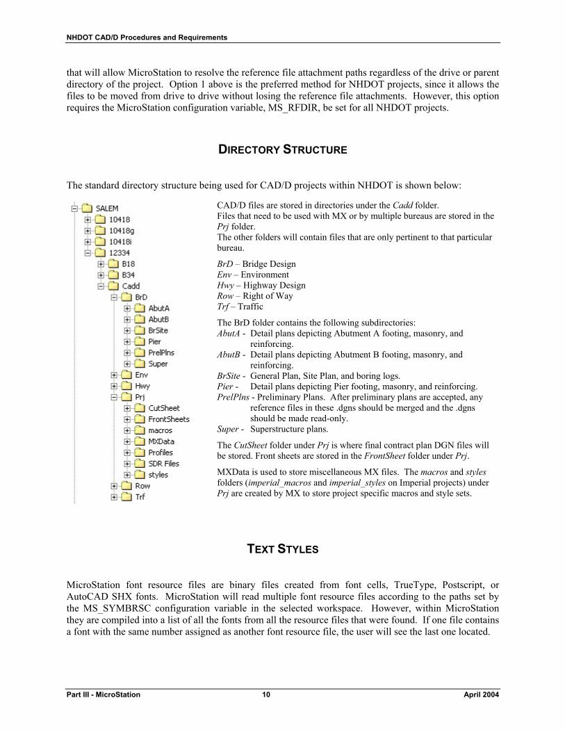
The standard directory structure being used for CAD/D projects within NHDOT is shown below:
TEXT STYLES
MicroStation font resource files are binary files created from font cells, TrueType, Postscript, or AutoCAD SHX fonts. MicroStation will read multiple font resource files according to the paths set by the MS_SYMBRSC configuration variable in the selected workspace. However, within MicroStation they are compiled into a list of all the fonts from all the resource files that were found. If one file contains a font with the same number assigned as another font resource file, the user will see the last one located.
CAD/D files are stored in directories under the Cadd folder. Files that need to be used with MX or by multiple bureaus are stored in the Prj folder. The other folders will contain files that are only pertinent to that particular bureau.
BrD – Bridge Design Env – Environment Hwy – Highway Design Row – Right of Way Trf – Traffic
The BrD folder contains the following subdirectories: AbutA - Detail plans depicting Abutment A footing, masonry, and
reinforcing. AbutB - Detail plans depicting Abutment B footing, masonry, and
reinforcing. BrSite - General Plan, Site Plan, and boring logs. Pier - Detail plans depicting Pier footing, masonry, and reinforcing. PrelPlns - Preliminary Plans. After preliminary plans are accepted, any
reference files in these .dgns should be merged and the .dgns should be made read-only.
Super - Superstructure plans.
The CutSheet folder under Prj is where final contract plan DGN files will be stored. Front sheets are stored in the FrontSheet folder under Prj.
MXData is used to store miscellaneous MX files. The macros and styles folders (imperial_macros and imperial_styles on Imperial projects) under Prj are created by MX to store project specific macros and style sets.
NHDOT CAD/D Procedures and Requirements
April 2004 11 Part II - MicroStation
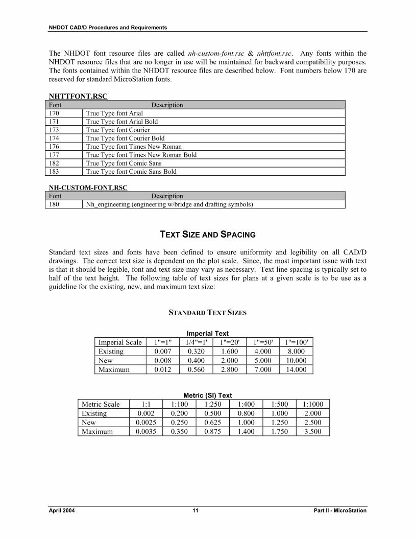
The NHDOT font resource files are called nh-custom-font.rsc & nhttfont.rsc. Any fonts within the NHDOT resource files that are no longer in use will be maintained for backward compatibility purposes. The fonts contained within the NHDOT resource files are described below. Font numbers below 170 are reserved for standard MicroStation fonts. NHTTFONT.RSC Font Description 170 True Type font Arial 171 True Type font Arial Bold 173 True Type font Courier 174 True Type font Courier Bold 176 True Type font Times New Roman 177 True Type font Times New Roman Bold 182 True Type font Comic Sans 183 True Type font Comic Sans Bold NH-CUSTOM-FONT.RSC Font Description 180 Nh_engineering (engineering w/bridge and drafting symbols)
TEXT SIZE AND SPACING
Standard text sizes and fonts have been defined to ensure uniformity and legibility on all CAD/D drawings. The correct text size is dependent on the plot scale. Since, the most important issue with text is that it should be legible, font and text size may vary as necessary. Text line spacing is typically set to half of the text height. The following table of text sizes for plans at a given scale is to be use as a guideline for the existing, new, and maximum text size:
STANDARD TEXT SIZES
Imperial Text Imperial Scale 1"=1" 1/4"=1' 1"=20' 1"=50' 1"=100' Existing 0.007 0.320 1.600 4.000 8.000 New 0.008 0.400 2.000 5.000 10.000 Maximum 0.012 0.560 2.800 7.000 14.000
Metric (SI) Text Metric Scale 1:1 1:100 1:250 1:400 1:500 1:1000 Existing 0.002 0.200 0.500 0.800 1.000 2.000 New 0.0025 0.250 0.625 1.000 1.250 2.500 Maximum 0.0035 0.350 0.875 1.400 1.750 3.500

NHDOT CAD/D Procedures and Requirements
Part III - MicroStation 12 April 2004
LINE STYLES
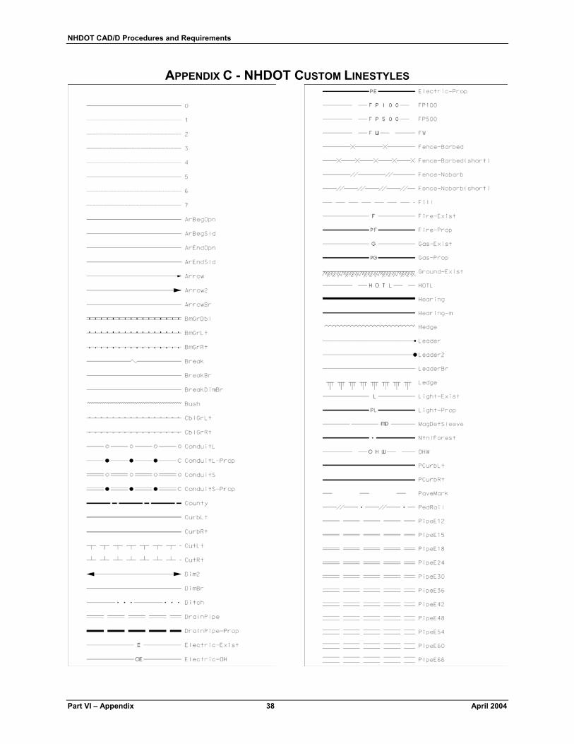
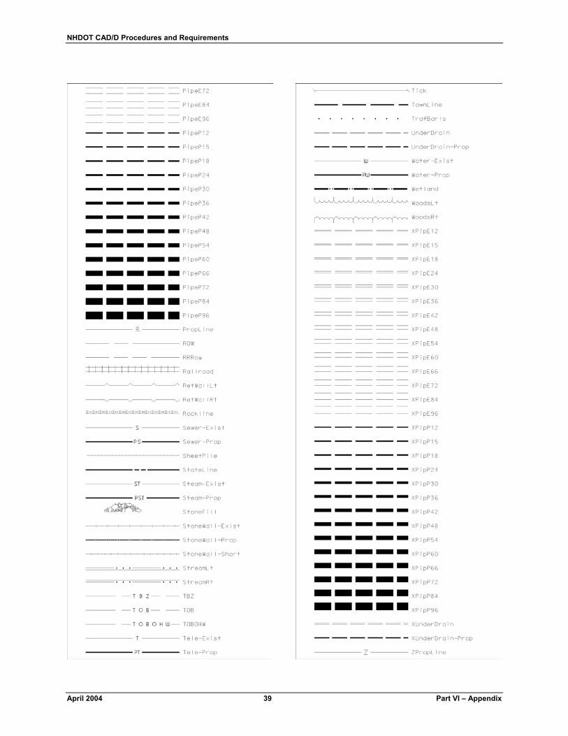
Line style is part of the symbology of graphical elements in MicroStation. An element can be set to the standard MicroStation line styles (numbered 0 - 7) or to a custom line style defined in a custom line style resource file. Custom line styles are user definable resource files for the display of different patterns, for example, a tree line, fence line, guardrail, etc. When an element is drawn in MicroStation with a custom line style, the definition of the line style is not contained within the design file. The resource file from which it was selected must be packaged with the design file and it must be found by MicroStation's configuration in order to properly display the line. Therefore, users are strongly discouraged from creating their own custom line styles. Use the NHDOT supplied custom line style resources whenever practical. Graphical depictions of NHDOT MicroStation linestyles are shown in Appendix C - NHDOT Custom Linestyles on page 38.
NHDOT CUSTOM LINE STYLE RESOURCE FILES
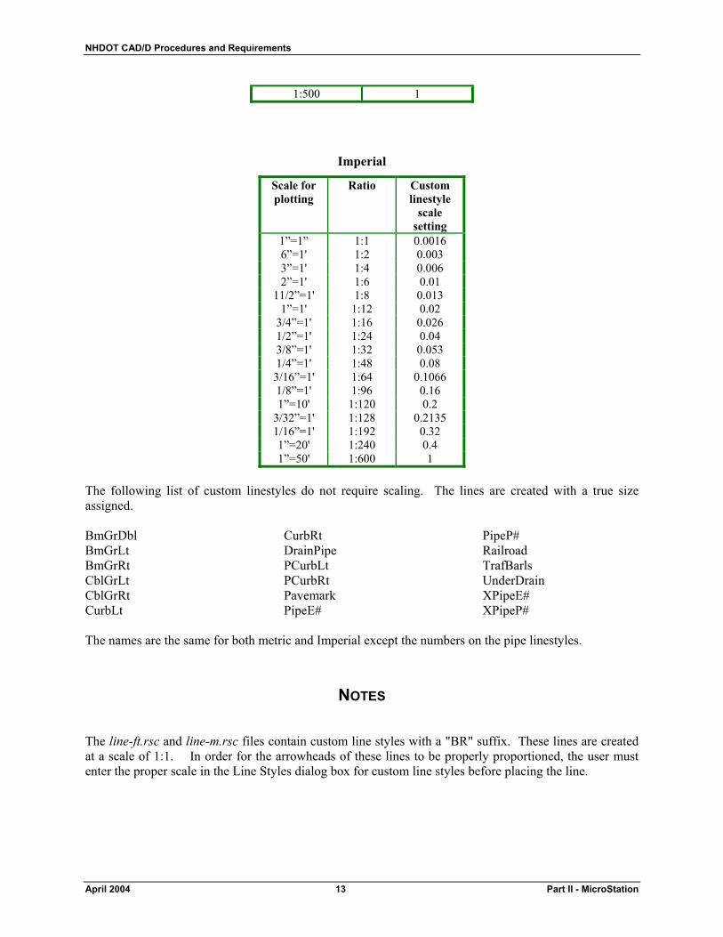
As mentioned above, custom line styles are user definable in MicroStation. Styles for plan drawings have been created for use on a 1:500 scale (1”=50') drawing. Linestyles that are not defined to be a specific width (such as pipe and railroad styles) need to be scaled to display properly on other scale plan drawings. Linestyles used on 1:250-scale metric drawings should be scaled by 0.5 and those used on 1"=20' Imperial drawings should be scaled by 0.4. These settings will be included in the GDM rules files. The GDM programs are described in more detail in Drawing Quality Assurance / Quality Control on page 27. Caution must be exercised as the definition for the line style is maintained in a resource file and a design file only contains links to custom line style resource files. If a new (non-standard) custom linestyle is developed by a user, those resource files must be delivered with the project. Users shall not modify the NHDOT delivered standard custom line style files.
CUSTOM LINESTYLE SCALING CHARTS
Metric
Scale for plotting Custom linestyle scale setting
1:1 0.002 1:2 0.004 1:5 0.01
1:10 0.02 1:20 0.04 1:25 0.05 1:50 0.1
1:100 0.2 1:250 0.5
Standard NHDOT Custom line style files Imperial Metric line-ft.rsc line-m.rsc pipe-ft.rsc pipe-m.rsc
NHDOT CAD/D Procedures and Requirements
April 2004 13 Part II - MicroStation
1:500 1
Imperial
Scale for plotting
Ratio Custom linestyle
scale setting
1”=1” 1:1 0.0016 6”=1' 1:2 0.003 3”=1' 1:4 0.006 2”=1' 1:6 0.01
11/2”=1' 1:8 0.013 1”=1' 1:12 0.02
3/4”=1' 1:16 0.026 1/2”=1' 1:24 0.04 3/8”=1' 1:32 0.053 1/4”=1' 1:48 0.08
3/16”=1' 1:64 0.1066 1/8”=1' 1:96 0.16 1”=10' 1:120 0.2
3/32”=1' 1:128 0.2135 1/16”=1' 1:192 0.32 1”=20' 1:240 0.4 1”=50' 1:600 1
The following list of custom linestyles do not require scaling. The lines are created with a true size assigned. BmGrDbl BmGrLt BmGrRt CblGrLt CblGrRt CurbLt
CurbRt DrainPipe PCurbLt PCurbRt Pavemark PipeE#
PipeP# Railroad TrafBarls UnderDrain XPipeE# XPipeP#
The names are the same for both metric and Imperial except the numbers on the pipe linestyles.
NOTES
The line-ft.rsc and line-m.rsc files contain custom line styles with a "BR" suffix. These lines are created at a scale of 1:1. In order for the arrowheads of these lines to be properly proportioned, the user must enter the proper scale in the Line Styles dialog box for custom line styles before placing the line.
NHDOT CAD/D Procedures and Requirements
Part III - MicroStation 14 April 2004
COLOR TABLE
A standard color table is necessary to provide visual consistency thus allowing users to easily identify elements in shared files and for consistency in color plotting. NHDOT has its own default color table called nh-color.tbl. The table defines 256 colors from which an active color can be selected and applied to an element.
CELL FILES
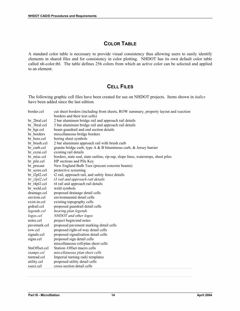
The following graphic cell files have been created for use on NHDOT projects. Items shown in italics have been added since the last edition. border.cel cut sheet borders (including front sheets, ROW summary, property layout and xsection
borders and their text cells) br_2bral.cel 2 bar aluminum bridge rail and approach rail details br_3bral.cel 3 bar aluminum bridge rail and approach rail details br_bgr.cel beam guardrail and end section details br_borders miscellaneous bridge borders br_bore.cel boring sheet symbols br_brush.cel 2 bar aluminum approach rail with brush curb br_curb.cel granite bridge curb, type A & B bituminous curb, & Jersey barrier br_exrai.cel existing rail details br_misc.cel borders, state seal, state outline, rip-rap, slope lines, waterstops, sheet piles br_pile.cel HP sections and Pile Key br_precast New England Bulb Tees (precast concrete beams) br_scree.cel protective screening br_t2pl2.cel t2 rail, approach rail, and safety fence details br_t3pl2.cel t3 rail and approach rail details br_t4pl2.cel t4 rail and approach rail details br_weld.cel weld symbols drainage.cel proposed drainage detail cells environ.cel environmental detail cells exist-in.cel existing topography cells grdrail.cel proposed guardrail detail cells legends.cel hearing plan legends logos.cel NHDOT and other logos notes.cel project begin/end notes pavemark.cel proposed pavement marking detail cells row.cel proposed right-of-way detail cells signals.cel proposed signalization detail cells signs.cel proposed sign detail cells miscellaneous roll/plan sheet cells StnOffset.cel Station–Offset macro cells stamps.cel miscellaneous plan sheet cells turnrad.cel Imperial turning radii templates utility.cel proposed utility detail cells xsect.cel cross-section detail cells
NHDOT CAD/D Procedures and Requirements
April 2004 15 Part II - MicroStation
The following pattern cell file has been created for use on NHDOT projects. nhpatern.cel Hearing plan removal patterns
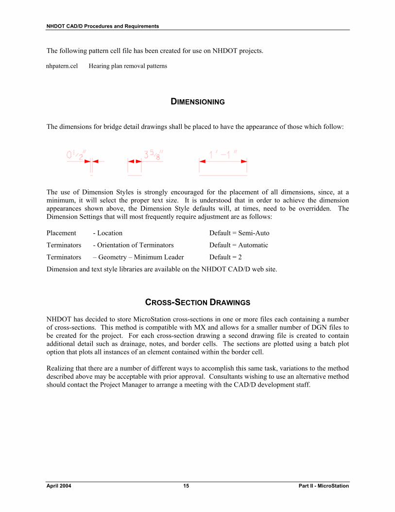
DIMENSIONING
The dimensions for bridge detail drawings shall be placed to have the appearance of those which follow: The use of Dimension Styles is strongly encouraged for the placement of all dimensions, since, at a minimum, it will select the proper text size. It is understood that in order to achieve the dimension appearances shown above, the Dimension Style defaults will, at times, need to be overridden. The Dimension Settings that will most frequently require adjustment are as follows: Placement - Location Default = Semi-Auto
Terminators - Orientation of Terminators Default = Automatic
Terminators – Geometry – Minimum Leader Default = 2
Dimension and text style libraries are available on the NHDOT CAD/D web site.
CROSS-SECTION DRAWINGS
NHDOT has decided to store MicroStation cross-sections in one or more files each containing a number of cross-sections. This method is compatible with MX and allows for a smaller number of DGN files to be created for the project. For each cross-section drawing a second drawing file is created to contain additional detail such as drainage, notes, and border cells. The sections are plotted using a batch plot option that plots all instances of an element contained within the border cell. Realizing that there are a number of different ways to accomplish this same task, variations to the method described above may be acceptable with prior approval. Consultants wishing to use an alternative method should contact the Project Manager to arrange a meeting with the CAD/D development staff.
NHDOT CAD/D Procedures and Requirements
Part III - MicroStation 16 April 2004
DETAIL SHEETS
A single detail sheet frequently requires the placement of several details of various scales. To accomplish this, all details shall be drawn at a scale of 1:1 while using the NHDOT standard working units defined within the NHDOT seed files. The detail sheet shall be composed by applying scale factors to the self-referenced attachments of the detail drawing. The border of the detail sheet shall be a cell placed on the drawing at a scale of 1. Detail drawings shall not be created by either increasing the scale of the border or by temporarily adjusting the working units of the file, in any way.
PLOTTING
The plotter driver file (file extension .PLT) is used to set default plotter settings. Style records used within NHDOT .PLT files are taken directly from the Bentley supplied hpgl2.plt file. Black and white plot drivers have been modified to force all pen colors to black except pens 10-14 which are defined as various shades of gray in the NHDOT color table. The following lines have been added to black and white plot drivers: ;plot colors 1-9,15-254 black pen(1)=(1-9,15-254)/rgb(0,0,0) The following lines replaced the lines in the Bentley supplied black and white plot drivers:
; units for weight stroke are multiples of .025 mm
weight_strokes=(3,8,13,18,25,30,35,40,45,50,55,60,65,70,75,80,85,90,95,100,105,110,115,120,125,130,135,140,145,150,155,160)
largest_polygon=2048
NHDOT CAD/D Procedures and Requirements
April 2004 17 Part II - MicroStation
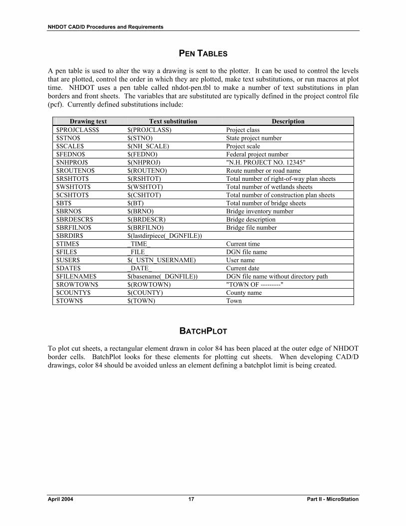
PEN TABLES
A pen table is used to alter the way a drawing is sent to the plotter. It can be used to control the levels that are plotted, control the order in which they are plotted, make text substitutions, or run macros at plot time. NHDOT uses a pen table called nhdot-pen.tbl to make a number of text substitutions in plan borders and front sheets. The variables that are substituted are typically defined in the project control file (pcf). Currently defined substitutions include:
Drawing text Text substitution Description $PROJCLASS$ $(PROJCLASS) Project class $STNO$ $(STNO) State project number $SCALE$ $(NH_SCALE) Project scale $FEDNO$ $(FEDNO) Federal project number $NHPROJ$ $(NHPROJ) "N.H. PROJECT NO. 12345" $ROUTENO$ $(ROUTENO) Route number or road name $RSHTOT$ $(RSHTOT) Total number of right-of-way plan sheets $WSHTOT$ $(WSHTOT) Total number of wetlands sheets $CSHTOT$ $(CSHTOT) Total number of construction plan sheets $BT$ $(BT) Total number of bridge sheets $BRNO$ $(BRNO) Bridge inventory number $BRDESCR$ $(BRDESCR) Bridge description $BRFILNO$ $(BRFILNO) Bridge file number $BRDIR$ $(lastdirpiece(_DGNFILE)) $TIME$ _TIME_ Current time $FILE$ _FILE_ DGN file name $USER$ $(_USTN_USERNAME) User name $DATE$ _DATE_ Current date $FILENAME$ $(basename(_DGNFILE)) DGN file name without directory path $ROWTOWN$ $(ROWTOWN) "TOWN OF ---------" $COUNTY$ $(COUNTY) County name $TOWN$ $(TOWN) Town
BATCHPLOT
To plot cut sheets, a rectangular element drawn in color 84 has been placed at the outer edge of NHDOT border cells. BatchPlot looks for these elements for plotting cut sheets. When developing CAD/D drawings, color 84 should be avoided unless an element defining a batchplot limit is being created.


NHDOT CAD/D Procedures and Requirements
April 2004 19 Part III - MX
PART III – MX
FILE NAMING
MX files should be named in such a way that someone unfamiliar with the project can figure out what the file is for. MX projects are typically given names beginning with the town name followed by the state project number. For example: Concord 12345.mmd. Other file types are listed in the table below.
Type Extension Description Input .INP Used to store line mode commands to create or modify MX strings Output .PRN Used to store the results of an input file or interactive commands Draw .DRW An input file that is used to create a display using a drawing macro or major option DRAW
and/or ENHANCE commands Journal .JOU A journal file stores commands issued during an MX session so they can rerun at a later
time
MODEL NAMING
Suggested MX model names are listed in Appendix D – MX Model Naming Convention, on page 41. Any variations from this convention shall be noted in the project journal file.
STRING LABELING
MX data is contained in strings and the strings are contained in models. Each string has a unique four-character label. Typically the first two characters of the string label are used to identify the type of string. NHDOT will continue to use the existing survey detail string labeling convention that was implemented with MOSS (the VMS version of MX). The existing detail string labeling convention is shown in Appendix E – MX Detail String Labeling Convention (Topical) and Appendix F – MX Detail String Labeling Convention (Alphabetical) on pages 45 (topical listing) and 51 (alphabetical listing).
NHDOT CAD/D Procedures and Requirements
Part III - MX 20 April 2004
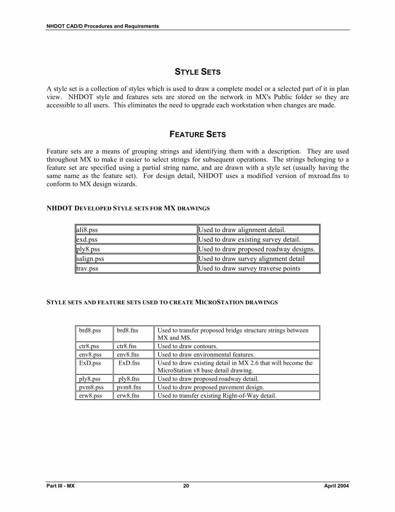
STYLE SETS
A style set is a collection of styles which is used to draw a complete model or a selected part of it in plan view. NHDOT style and features sets are stored on the network in MX's Public folder so they are accessible to all users. This eliminates the need to upgrade each workstation when changes are made.
FEATURE SETS
Feature sets are a means of grouping strings and identifying them with a description. They are used throughout MX to make it easier to select strings for subsequent operations. The strings belonging to a feature set are specified using a partial string name, and are drawn with a style set (usually having the same name as the feature set). For design detail, NHDOT uses a modified version of mxroad.fns to conform to MX design wizards.
NHDOT DEVELOPED STYLE SETS FOR MX DRAWINGS
ali8.pss Used to draw alignment detail. exd.pss Used to draw existing survey detail. ply8.pss Used to draw proposed roadway designs. salign.pss Used to draw survey alignment detail trav.pss Used to draw survey traverse points
STYLE SETS AND FEATURE SETS USED TO CREATE MICROSTATION DRAWINGS
brd8.pss brd8.fns Used to transfer proposed bridge structure strings between MX and MS.
ctr8.pss ctr8.fns Used to draw contours. env8.pss env8.fns Used to draw environmental features. ExD.pss ExD.fns Used to draw existing detail in MX 2.6 that will become the
MicroStation v8 base detail drawing. ply8.pss ply8.fns Used to draw proposed roadway detail. pvm8.pss pvm8.fns Used to draw proposed pavement design. erw8.pss erw8.fns Used to transfer existing Right-of-Way detail.

NHDOT CAD/D Procedures and Requirements
April 2004 21 Part III - MX
DRAWING MACROS
In addition to the style and feature sets mentioned above, MX users can also draw detail and sections with drawing macros. A number of these macros have been developed and are available for download from the NHDOT website.
CROSS-SECTION SETTINGS FILES
Cross sections and profiles can be generated in a number of different ways. Using the cross-section wizard within MX allows the user to save parameters defining the cross-section set. These saved settings files have a .CSU extension and are stored in the project directory. The settings file will define the type of sections cut (based on the cross-section feature set used), models selected, and information about any special stations or skewed sections. By default, the cross-section wizard uses the information in the MfW Cross Section.fns to determine the different type of cross-sections. NHDOT has modified this file for its use.
MACRO SYMBOLS & LINES
Symbols for use with MX software, including standard line patterning symbols, are available in the MX .MMS and .MML file formats. Since line and symbol size is defined in the MX style sets, the same line and symbol definitions are used for both metric and Imperial projects. This data is available on the NHDOT website or can be requested through the Project Manager.

NHDOT CAD/D Procedures and Requirements
April 2004 23 Part IV – Other Project Data
PART IV – OTHER PROJECT DATA
PROJECT JOURNAL FILES
PROJECT JOURNAL GUIDELINES
A Project Journal will be produced and delivered with each electronic project plan submission. The purpose for this journal is to aid downstream customers of the CAD/D data so they may utilize existing CAD/D work in their processes. The format of the journal will be an electronic file, either in text format or a format supported by Microsoft Word 2000. As a minimum, the journal will contain the following information:
• A listing (Index) of the files delivered, including brief descriptions of each file and where the file is located.
• Documentation about the CAD/D software used, special CAD/D decisions made, exceptions to standards that were made, problems encountered and work around, or other important issues that arose during the course of the CAD/D work. For example, if a custom line style needed to be created, the justification, resource file, and files where that line style was used would be documented in the Journal. Other documentation such as the design software used, particular software settings, and other information that would help a downstream user of the data understand where and how the data was created should be documented.
NHDOT has not established a specific format for the Journal file. The sample file shown on the following pages should be used a guideline for the type of information to be included and format that is expected. Important data that should also be contained in the Journal include:
• All information necessary for the regeneration or use of those files by subsequent customers of the CAD/D data
• Document the design data, controlling alignment and profile names and geometry input/output files, relevant survey information, cross sections and the methodology used to obtain the final geometric controls in the CAD/D product.
The project journal must be kept up to date as the CAD/D design work progresses and be delivered with the project on the preferred media for archival purposes.
NHDOT CAD/D Procedures and Requirements
Part IV – Other Project Data 24 April 2004
EXAMPLE OF CAD/D PROJECT JOURNAL
CAD/D PROJECT JOURNAL
(00000_project_index.doc) 4/13/00
PROJECT JOURNAL This file contains information about the project 12345 and the corresponding electronic files contained in the project directory. This file should be kept up to date and archived with the project's electronic files. When filling in the required information, please delete the instructions and examples in order to maintain a concise record.
PROJECT DESCRIPTION
State Project Number: 12345 Federal Aid Number: N/A County: Merrimack Project Manager: Project Manager Project Designer: Project Designer Project Directory: M:\pbt\town\12345\cadd\prj
SCOPE OF WORK
The scope of work for project 12345 goes here. Include as much detail as necessary to define the work done for the project.
PROJECT FILES
List any files that to not fit into the standard naming convention. Include a brief description of the data contained in each one.
MICROSTATION FILE INFORMATION
Non-Standard Drawings
List any drawings that are not on the standard naming convention list with a brief description of each one's contents.
Plot Information
List information about batch plot specifications, pen tables, or other features used to generate the plot files.
NHDOT CAD/D Procedures and Requirements
April 2004 25 Part IV – Other Project Data
MX FILE INFORMATION (or information for other design programs used)
MX Topo input file: topo.inp
Preliminary Design Engineer: Your Name
Final Design Team Leader: Team Leader
MX Design Input File Names Description
pdesign-mc0m.inp The file that creates the alignment MC0M and design strings up to and including the interface stage.
psectmc0m.inp Creates the old ground and proposed cross-sections for alignment MC0M
TEXT FILES
Include information about output files, genio files, or other ASCII files provided with the project drawings.
SPECIAL INFORMATION/COMMENTS This job was designed with MX version 2.6.3. We had problems getting some cross-sections working, so we estimated the earthwork in that area (123+00 to 125+00). When job was completed, there was a design change that affected cross sections. Earthwork was minimal so we did not recalculate earthwork in the area of 195+00 to 202+00. Cross Section Info (Main Line) Existing Cross Sections Master Alignment Model: PALIGN Master Alignment Name: .MC1M Description: ......................Main St. (NH 100) Triangle String:.................TRIA Cross Section Model:........PDESIGN MC1M SECTIONS Cross Section Label: .........E Proposed Cross Sections Design Model: ..................PDESIGN MC1M Master Alignment Name: .MC1M Description: ......................Main St. (NH 100) Triangule String:...............TRIA
NHDOT CAD/D Procedures and Requirements
Part IV – Other Project Data 26 April 2004
Cross Section Model:........PDESIGN MC1M SECTIONS Cross Section Label: .........D Cross Section Info (Side Road) Description: ......................Pleasant St. Master Alignment Model: PDESIGN MC2A Master Alignment Name: .MC2A Cross Section Model:........PDESIGN MC2A SECTIONS Existing Cross Sections Triangle Model: ................TRIANGLES Triangle String:.................TX00 Cross Section Label: .........E Proposed Cross Sections Cross Section Label: .........D Mask File:.........................2.msk Additional Section Sets Cross Section Label: .........X Description: ......................Existing ground feature labels Cross Section Label: .........A Description: ......................Sections of Side Road cut from Main St. alignment

NHDOT CAD/D Procedures and Requirements
April 2004 27 Part IV – Other Project Data
DRAWING QUALITY ASSURANCE / QUALITY CONTROL
To aid the consultant and in-house staff in developing a set of contract plans that conform to the requirements contained in this document, NHDOT has purchased QA/QC software that works with MicroStation drawings. These utilities, provided by GDM Software of Calgary, Alberta, will work from a set of "rule" files based on the established MicroStation standards. It is the intent of NHDOT to distribute a read-only version of this software, at no cost, to consultants with active NHDOT projects to be used to check the drawings before they are submitted. The software can also be used in the creation of the drawings. At this time, use of the drafting tools is optional although their use is strongly encouraged. The QA/QC software contains a number of components. They include:
QA_INPUT
As an upgrade and replacement for Settings Manager, QA_Input provides a "cascaded" or hierarchical flyout menu derived from the CAD/D drawing standard. Starting from the Rules pull-down menu, a feature is selected from the categories and sub-categories provided. QA_Input will set the correct level, weight, color, style, font, text size, active cell, etc. and activate the relevant placement command.
QUIKCHEK
QuikChek checks the active design file to ensure all elements have used valid drawing parameters. Errors are identified and corrected by category or by individual occurrence, at the user's option. Corrections are specified by selecting entries from the drawing standard, using the same interface described above in QA_Input. QuikChek will also suggest possible corrections from the closest matches to the drawing standards.
SPOT_FIX
Spot_Fix is a general-purpose proofreading tool. Spot_Fix will gray the display of an entire file, and then highlight items matching the rule(s) selected from the cascaded menu. The user can concentrate on one aspect of a file at a time, and spot anomalies with a quick visual examination. MicroStation commands or the tools provided in Spot_Fix can be used to correct the problem.

NHDOT CAD/D Procedures and Requirements
April 2004 29 Part V – Engineering Consultant Requirements
PART V – ENGINEERING CONSULTANT REQUIREMENTS
OVERVIEW
The purpose of this section is to establish the minimum acceptable criteria for electronic CAD/D deliverables. Obtaining drawings and ground models in a common format will reduce the amount of time spent becoming familiar with the designs if they are transferred from one designer to another and allows for their reuse in the future.
FILE FORMAT AND DELIVERY
REQUIREMENTS FOR SUBMITTING ELECTRONIC DATA TO NHDOT
All electronic data furnished to the NHDOT shall use the appropriate naming scheme and format for the type of data to be transmitted. It is very important to clearly communicate what is being transmitted and to describe the format of the transmitted files. A letter is to be attached to all submissions stating briefly: 1. File content 2. File Format (zipped, MicroStation, MX, etc. and the utility used) 3. MX or MicroStation version (SE, J, v8, etc.) 4. Number of diskettes, zip disks, etc. 5. Files must be in the proper format before transmitting to NHDOT. No translating of
information by NHDOT personnel shall be required. 6. If files are zipped or backed up, a brief explanation of the recommended procedure to extract the
files should be included. 7. Versions of software must be current to or fully compatible with that of the NHDOT. 8. Each disk submitted shall be labeled and dated with a minimum of the State Project # and date. If
a series of disks are transmitted, the disk label shall also include the disk number and the total disks of that set, (ex: 1 of 10). Other subsequent disks shall be labeled so as to uniquely identify each group or set and shall include the sequence number followed by the total number in the group (ex: 2 of 10, 3 of 10, etc.)
9. NHDOT reserves the right to reject any file transmitted that does not conform to these requirements.
DATA SUBMISSION
In addition to hard copy drawings specified by the contract, the consultant shall submit electronic drawing files in MicroStation .DGN file format. Electronic files shall be delivered on one of the following in order of preference:
a) CD-ROM b) Zip Drive Cassette c) 3½” floppy disk
NHDOT CAD/D Procedures and Requirements
Part V – Engineering Consultant Requirements 30 April 2004
The final submission shall include all files necessary to reproduce the cut sheet drawings as well as copies of the original “roll-plan” drawings used to generate the cut sheets. Documentation of procedures and project history shall be maintained in a Project Journal File. An in-depth description of the Project Journal File is in PART IV – OTHER PROJECT DATA beginning on page 23. The Project Journal File will be provided with the submission. Any drawings not included in the NHDOT standard drawing list will be identified and will include a description of levels used on each drawing. Detailed descriptions of the data to be provided by NHDOT to the consultant and expected deliverables at various stages of the project's development are included in the next section. If MicroStation tables for linestyles, multilines, level tables, symbology tables, database, special fonts, or any special user defined feature is used, that information must be provided and shall become property of NHDOT. Similarly, any MX macro, symbol, linestyle, style set, or feature set developed by the consultant and necessary to properly display the project data shall become property of NHDOT. Any MX input file developed to generate, enhance, or alter the project's design that the consultant feels would be beneficial to future designers of the project should also be provided. A name and description of each file must also be provided. NHDOT will not distribute these items to any other individual, consultant or State Transportation Department without prior permission of the developer.
DEVIATION FROM FORMAT
Any file to be submitted that deviates from the above-mentioned format must have prior NHDOT approval. The approval must be in writing with the name of the individual from NHDOT who permitted the varying format.
MICROSTATION ONLY DELIVERABLE
For projects that were initiated after April 18, 2002, NHDOT will only accept plan drawings that were developed in MicroStation. Translations from AutoCAD or any other CAD/D software will no longer be allowed on those projects. Projects initiated before that date will continue to follow the guidelines in place at the time the project was initiated. Engineering consultants may, at their discretion, choose to follow a later copy of these guidelines.
MICROSTATION PLOT FILES (FINAL DESIGN CONSULTANTS ONLY)
In addition to MicroStation format drawings, plot files of project cut sheets in PDF format will be required at the completion of the project. Plot files should be named with the convention for plan sheets outlined on page 7 using a .PDF file extension. The consultant has the option to include all drawings in a single PDF file or create separate files, whichever is more convenient. The purpose of this requirement is to provide a viewable and reproducible copy of the drawing as it existed at the end of the consultant contract.

NHDOT CAD/D Procedures and Requirements
April 2004 31 Part V – Engineering Consultant Requirements
FILE CONVERSION
This information only applies to projects initiated prior to April 18, 2002. Translation tables, conversion tables, or special software programs have not been created or standardized for exchanging information between common file formats such as DXF, DWG, ICES, IGES, or software such as AutoCAD, ARCVIEW, ARCINFO, GDS, etc. MicroStation provides methods for exchanging select file types but data is often modified during the process. The Consultant is solely responsible for any translation and verification required to convert non-MicroStation graphics files to the current NHDOT MicroStation design file format. All translated design files shall conform to the standards adopted by NHDOT for electronic plans and the specifications required in this document. Those files shall be converted to MicroStation and thoroughly reviewed prior to transmitting to NHDOT. The consultant shall be prepared to submit a sample cut sheet, profile, typical or detail, and/or cross-section sheet for review of conformity to the NHDOT CAD/D specifications at various stages of the project's development. As a minimum, the final design consultant should be prepared to submit electronic project drawings at the Preliminary Plans, Specifications & Estimate (PPS&E) and PS&E stages of the project. Depending on the project, NHDOT may request electronic submissions at a more or less frequent interval.
NHDOT DESIGN PROCESS
This section is intended to describe the data that is to be provided when a project moves from one design phase to the next. There are two major transition points where Highway Design CAD/D data needs to be transferred: the turnover from the Plan Preparation Section to Preliminary Design and the one from Preliminary Design to Final Design.
PLAN PREPARATION The Plan Preparation section is responsible for taking project survey and preparing the digital terrain model (DTM) and base drawings that will be used during the design process. They should also be the ones to initiate the Project Journal File described in PART IV – OTHER PROJECT DATA beginning on page 23. By default, NHDOT design teams are working with 2-D drawings. If a consultant prefers to use 3-D drawings, this should be mentioned prior to obtaining design data from the Department.
Electronic data to be provided by Plan Preparation to:
Preliminary Design and consultants using MX software:
1. Copy of the MX modelfile 2. Copy of the topo input file (TOPO.INP) containing survey data and Plan Preparation
modifications/enhancements. 3. Copy of annotated MicroStation .DGN files developed for the project. 4. Copy of the Project Journal File
NHDOT CAD/D Procedures and Requirements
Part V – Engineering Consultant Requirements 32 April 2004
Consultants without MX software: 1. 3D DXF files of existing detail and triangulation generated from the MX modelfile 2. Copy of annotated MicroStation .DGN files developed for the project. 3. Copy of the Project Journal File
PRELIMINARY DESIGN
The Preliminary Design section is responsible for taking the data provided by the Plan Preparation section and designing the project up to the Public Hearing stage. This includes gathering all data necessary to prepare designs to be presented at the Public Officials Meeting, Public Informational Meetings, and Public Hearing. Electronic deliverables expected from consultants at the completion of the Preliminary Design process:
Consultants using MX software: 1. Copy of the MX modelfile 2. Copy of any input files available to recreate the submitted design 3. Copies of any macro symbols and macro line definitions used on the project that are not included
in the NHDOT standards 4. Copy of MicroStation .DGN files developed for the project 5. Copy of the Project Journal File
Consultants without MX software: 1. 3D DXF files generated from the design software used 2. Copy of project horizontal and vertical alignments in MX HALGN and VERAT formats.
Examples of HALGN and VERAT data can be found in Appendix H – MX Alignment Data Formats (HALGN & VERAT) on pages 59 and 61
3. Copy of MicroStation .DGN files developed for the project 4. Copy of the Project Journal File
Electronic data to be provided by Preliminary Design to:
Final Design and consultants using MX software: 1. Copy of the MX modelfile 2. Copy of the topo input file (TOPO.INP) containing survey data and Plan Preparation
modifications/enhancements 3. Copy of MicroStation .DGN files developed for the project 4. Copy of the Project Journal File
Consultants without MX software: 1. 3D DXF files generated from the MX modelfile 2. Copy of MicroStation .DGN files developed for the project 3. Copy of the Project Journal File
NHDOT CAD/D Procedures and Requirements
April 2004 33 Part V – Engineering Consultant Requirements
FINAL DESIGN
The Final Design section is responsible for taking the data provided by the Preliminary Design Section or Preliminary Design Consultant and designing the project up to the Contract Plans stage. This includes refining the project design as approved at the Public Hearing, preparing a project estimate, bid documents, and obtaining necessary construction permits. Electronic deliverables expected from a Final Design consultant at the project's completion:
All Consultants 1. Copy of MicroStation .DGN files developed for the project 2. Copy of the Project Journal File 3. COGO and coordinate reports of each alignment similar in format to the ones shown in Appendix
I – Construction Reports on page 63 4. Station and offset listing of proposed bounds 5. Plot files in PDF format of each contract plan sheet
Consultants using MX software: 1. Copy of the MX modelfile 2. Copy of any input files available to recreate the submitted design 3. Copies of any macro symbols and macro line definitions used on the project that are not included
in the NHDOT standards
Consultants without MX software: 1. 3D DXF files generated from the design software used 2. Copy of project horizontal and vertical alignments in MX HALGN and VERAT formats.
Examples of HALGN and VERAT data can be found in Appendix H – MX Alignment Data Formats (HALGN & VERAT)on pages 59 and 61
3. If the project was designed with InRoads/SelectCAD, include files mentioned below
PROJECTS DESIGNED USING INROADS/SELECTCAD
If a project is designed with InRoads/SelectCAD the following files should be delivered with other project data: Surface Files (*.dtm): These files contain the existing and proposed ground information. In Version 7.x
of InRoads they contain just the "triangulation". In the newest version of InRoads (SelectCAD) these files store the "triangulation" and other data. They will contain element types, i.e. edge of pavement, wetlands, buildings, and random shots.
Alignment Files (*.alg): These files contain the Horizontal, Vertical, and Superelevation information for a
project. Template Library (*.tml): These files contain the templates, Material Tables, Cut/Fill Tables, and
Decision Tables used to create the proposed design. Decision Tables work basically the same as an interface macro. Templates are similar to MX templates.
NHDOT CAD/D Procedures and Requirements
Part V – Engineering Consultant Requirements 34 April 2004
Roadway Library (*.rwl): These files tell InRoads how to apply the templates and decision tables. Preference Files (*.prf or *.ini): In Version 7.x of InRoads these files control the display of design
information in InRoads; how InRoads draws profiles, sections, alignments, and design data. If SelectCAD is used then civil.ini and wysiwyg.ini preferences should be provided. These two files control how all information is displayed in SelectCAD (These files are very similar to the .prf files).
Custom Cross Section files (*.xsc): These files contain a list of stations and offsets for InRoads to display
sections. They will contain constant intervals, special stations, and skewed sections.
SPECIALIZED DEVELOPMENT BY DESIGN CONSULTANTS
Any specialized programs, macros, utilities, symbology, etc., developed by the consultant that are necessary to properly display drawings submitted to NHDOT shall be included with other project deliverables.
Submission of copies of other specialized programs, macros, utilities, symbology, etc. developed to improve MicroStation and MX drafting and design processes is encouraged. It is understood that NHDOT accepts these items without any guarantee of usefulness or expectations of support by the developer. In addition, NHDOT will not distribute these items to any other individual, consultant or State Transportation Department without prior permission of the developer.
NHDOT RESOURCES AVAILABLE FOR CONSULTANTS
To assist in the production of the required CAD/D files, NHDOT has provided MX and MicroStation support files available from the Department's web site. The site address is listed in Part I – General Introduction.
NHDOT CAD/D Procedures and Requirements
April 2004 35 Part VI – Appendix
PART VI - APPENDIX
APPENDIX A - MICROSTATION DRAWING NAMES
MicroStation drawing names will begin with the NHDOT state project number followed by the drawing type. The tables below show the text that will follow the project number along with a description of the drawing.
For example: 12345ALI.DGN would contain alignment data for project 12345.
HIGHWAY DESIGN DRAWINGS (Names in italics have been added since the previous version of this document)
ALI Alignment CLR Final Design Color CTR Existing Contours DET Detour EDU Existing Digitized
Utilities ENV Environment ERW Existing Right-of-Way EXD Existing Detail EXF Field check data EXU Existing utilities
HER Hearing plan HHO Informational Handout LOC Project Location Map LND Landscaping MTH Match Lines PDR Proposed Drainage PGR Proposed guard-rail PLY Proposed layout PNT Proposed notes PRO_MCxx Profile PRW Proposed Right-of-Way
PSG Proposed signalization PSN Proposed signing PUT Proposed utilities PVM Pavement Markings PWT Proposed Wetlands TXT Existing Text XS_MCxx
Cross-section XSU Section Details
CUT SHEET DRAWING TYPES x or xx indicates a sequential number Bxx Base Sheets Cxx Curbing & Pavement
Layout Dxx Drainage Exx Detour FSC Front Sheet-
Construction FSR Front Sheets-ROW
FSW Front Sheet-Wetlands Gxx General Plans Mxx Pavement Marking Pxx Profiles PLx Property Layout Rxx Right-of-Way RSx Row Summary Sheet Sxx Signing
SGx Signalization SMx Summary Sheet STx Sign Text Layout Txx Traffic Control
Plans TYx Typicals Wxx Wetland
NHDOT CAD/D Procedures and Requirements
Part V – Engineering Consultant Requirements 36 April 2004
BRIDGE DESIGN DRAWINGS (All bridge drawing names were altered since the previous document)
AbutA A-Abut Abutment A Masonry (formerly AAM) A-Rebar Abutment A Reinforcement (formerly AAR) A-Wings Abutment A Wings A-ReWings Abutment A Wings Reinforcement A-Foot Footing A Masonry (formerly FAM) A-ReFoot Footing A Reinforcement (formerly FAR)
AbutB B-Abut Abutment B Masonry (formerly ABM) B-Rebar Abutment B Reinforcement (formerly ABR) B-Wings Abutment B Wings B-ReWings Abutment B Wings Reinforcment B-Foot Footing B Masonry (formerly FBM) B-ReFoot Footing B Reinforcement (formerly FBR)
Pier Pier1 Pier 1 Masonry (formerly P1M) Re-Pier1 Pier 1 Reinforcement (formerly P1R) Pier2 Pier 2 Masonry (formerly P2M) Re-Pier2 Pier 2 Reinforcement (formerly P2R)
Box BX-Deck Box Deck (formerly BXD) BX-ReDeck Box Deck Reinforcement BX-Foot Box Footing (formerly BXF) BX-ReFoot Box Footing Reinforcement BX-Wings Box Wings Masonry (formerly BXM)
BX-ReWings Box Wings Reinforcement (formerly BXR) BX-Walls Box Walls (formerly BXW) BX-ReWalls Box Walls Reinforcement BX-Detls Box Details (formerly BDT
Frame FR-Detls Frame Details FR-Foot Frame Footing FR-ReFoot Frame Footing Reinforcement FR-ALeg Frame Leg A (formerly FLA) FR-ReALeg Frame Leg A Reinforcement FR-BLeg Frame Leg B (formerly FLB)
FR-ReBLeg Frame Leg B Reinforcement FR-Deck Frame Deck (formerly FRD) FR-ReDeck Frame Deck Reinforcement FR-Wings Frame Wings FR-ReWings Frame Wings Reinforcement
PrelimPlans Pre-Gen Preliminary Genplan (formerly PGP) Pre-Site Preliminary Site Plan (formerly PSP)
BrSite Genplan Genplan (formerly GNP) Siteplan Siteplan (formerly STP) Borings Borings (formerly BOR) Bor-Req Boring Request (formerly BRQ)
Devl-View Developed Views (formerly DEV) BrNotes Bridge Notes BrDetour Bridge Detour
Super DeckDetls Deck Details DeckBars Deck Reinforcing (formerly DRE) DeckSect Deck Section (formerly DXS) Girder Girder Layout and Details (formerly GLD)
FramePlan Framing Plan (formerly FRA) SSDetls Super Structure Details Shoes Bridge Shoes
April 2004 37
APPENDIX B - LEVEL MAPPING CONVENTION
Note: MicroStation level information was included in previous editions of this document. To reduce the potential for errors and conflicting data, this information has been removed. The latest mapping convention can be found on the NHDOT web-site at the address listed in the Disclaimer section of this document. Previous versions of the level mapping will be maintained on the website.
NHDOT CAD/D Procedures and Requirements
Part VI – Appendix 38 April 2004
APPENDIX C - NHDOT CUSTOM LINESTYLES
NHDOT CAD/D Procedures and Requirements
April 2004 39 Part VI – Appendix

NHDOT CAD/D Procedures and Requirements
April 2004 41 Part VI – Appendix
APPENDIX D – MX MODEL NAMING CONVENTION Note: These are the most commonly encountered models on a project. When creating
additional models, use names that easily and accurately reflect the information contained in the model.
PLAN PREPARATION MODELS (Models appear in approx. order of creation)
RAxxxxx Model containing a field surveyed traverse string PSSA. Traverses may be received as separate files (eg. RAxxxxx.SDR, RBxxxxx.SDR, etc. - where xxxxx is the project number). Individual traverses are typically combined to create a single traverse in this model. The Survey Section is responsible for closing/adjusting traverses.
TOPO Model containing existing project detail/topo strings as recorded in the field by survey data collectors. This model is created by editing then merging individual topo files (eg.TAxxxxx.SDR, TBxxxxx.SDR, etc. - xxxxx is the project number).
AERIAL DETAIL Model containing existing aerial survey detail obtained from an outside agency.
BOUNDARY A model containing one or more boundary strings (BDRY, BY01, etc.) Boundary strings may be used in merging models or controlling creation and trimming of the triangle string (although PBRK strings have generally superceded boundary string needs in triangulation).
TRIANGLES Model containing the triangulation string (TRIA) created by using select topo detail string information. Triangulation interrelates points on and between strings, creating a surface from which elevations can be extracted at any location.
CONTOURS Model containing the existing ground contour strings (0 [zero] = major, D = minor) created by surfacing (contouring) the TRIANGLES model.
SALIGN Model containing reference master alignments (MCxx) created using center of road shots (CO) to establish tangents and adding approximate curves (to nearest 15'). Reference alignments are used to cut profiles and cross sections which assist in verifying the accuracy of the TOPO & CONTOURS models via a field check. Existing ground elevations are attached to the master strings by sectioning them over the TRIANGLES model. Strings in this model must be refined (drive points added, etc.) if they are to be used for design purposes.
SSECT MCxx Model containing existing ground cross sections cut referencing the master string MCxx in SALIGN. Existing ground sections are cut over the TRIANGLES model at each point along the master string and assigned string labels beginning with 'E'.
Additional cross sections may be cut across select topo detail for annotation purposes (EP, TW, etc.). These are assigned a string label of 'D'. Separate section models are maintained for each unique master string.
NOTE: THESE MODELS ARE RECORD FILES! NO MODIFICATIONS ARE TO BE MADE WITHOUT THE PRIOR APPROVAL OF THE PLAN PREPARATION SECTION.
NHDOT CAD/D Procedures and Requirements
Part VI – Appendix 42 April 2004
PRELIMINARY DESIGN MODELS
OG PROFILES Model storing the master strings 'MCxx' (with existing ground or elevations), existing ground strings 'LCxx' and original geometry
OG PALIGN strings 'GCxx'. This model is used for back up purposes. Note that drive points need to be inserted on the master string if it has not already been done. Master strings are sectioned (177 over the TRIANGLES model or 171 over a CONTOURS & DETAIL model - only if no Triangles model exists) to attach existing ground elevations, then 'L' strings created (by specifying 'Lxxx' in the 3rd field). Once these steps are complete, the 'M', 'L', and 'G' strings are copied into the PALIGN model where proposed elevations will be attached.
PALIGN Model for storing all master strings 'MCxx' with proposed elevations, geometry 'GCxx' strings containing updated vertical information and existing ground elevation strings 'OCxx'. New elevations are attached to the master strings using the VERAT option. The vertical portion of the geometry string must be updated as well. This is accomplished by specifying a second model when using the VERAT option.
Note: Master 'MC' and associated ground 'OC' strings must reside in the same model to be drawn up or plotted together.
PDESIGN MCxP This model contains the master string 'MCxP' with proposed elevations (copied from PALIGN), and the associated template and interface strings (created with DESIGN and INTERFACe options). Separate design models are maintained for each study alternative to minimize masking requirements when cutting cross sections. Models may also include alignments for side roads and driveways.
PSECT MAxP Model containing existing, proposed, bottom of box, detail and subgrade cross sections for master string MCxP. Sections are to be labeled based on the following conventions: 'B' bottom of box, 'E' existing, 'F' proposed, 'D' detail (used for the purpose of annotating cross sections) and 'V' subgrade generated using the VOLSECT UPM. Separate cross section models are maintained for each master string. Related cross section strings must reside in a common model to allow overdraws.
For the most accurate results, existing cross sections 'E' should be cut over the TRIANGLES model. Older projects may not contain a TRIANGLES model. In this case, users need to create a model called CONTOURS & DETAIL containing the combined information of the two independent models - this will yield acceptable but less accurate results than sectioning over a TRIANGLES model.
Proposed sections 'F' are cut using the template, interface and proposed master string(s) stored in the PDESIGN MCxx model, while detail sections 'D' are cut over the TOPO model. Bottom of box sections are given a 'B' label. Subgrade sections 'V' are generated using the VOLSECT UPM and can be used to calculate preliminary cut and fill volumes.
SIGHT LINES Model intended to store sight lines for various alternates.
NOTE: THESE MODELS ARE INTENDED FOR PRELIMINARY USE ONLY AND ARE TECHNICALLY CONSIDERED 'RECORD' FILES. NO MODIFICATIONS ARE TO BE MADE WITHOUT THE APPROVAL OF THE PRELIMINARY DESIGN ENGINEER.
NHDOT CAD/D Procedures and Requirements
April 2004 43 Part VI – Appendix
FINAL DESIGN MODELS
When a project is turned over, the preliminary design engineer shall provide the team with a list of the moss models and pertinent strings in each. The final team will copy the pertinent strings into the appropriate Final Design models where work will progress. Final work should not be done in Preliminary Design models.
If the number of models becomes excessive, the Team should consider utilizing the MX ARCHIVE option. This enables removal of infrequently used models from the active MODEL.FIL and placement into an ARCHOLD.FIL. Use the LIST or RETRIEVE options to view or retrieve model information.
OG FALIGN FALIGN FDESIGN MCxx FSECT MCxx
FTRIANGLES Model containing the final triangulation string (TRIP) based on the proposed design template and interface strings contained in the FDESIGN MCxx model. A PBRK or boundary string may be created to prevent contours from being generated outside the limits of the interface (slope) lines. These string(s) would be stored in the appropriate FDESIGN MCxx model.
FCONTOURS Model to contain the final contours generated by surfacing the FTRIANGLES model.
Model descriptions are identical to Preliminary Design models with the exception that they are for Final Design use.

NHDOT CAD/D Procedures and Requirements
April 2004 45 Part VI – Appendix
APPENDIX E – MX DETAIL STRING LABELING CONVENTION (TOPICAL) Items added since previous edition are shown in italic print. GENERAL USE: Bench mark....................................................................PBMK Boring............................................................................PBOR Boundary String.............................................................BY Drill hole........................................................................PDHL Level string....................................................................L Spot elevations...............................................................PELV Spot elevations - Not at Ground ....................................PEVV Survey traverse string ....................................................PSSA Point labels within survey traverse string (PSSA) Traverse .........................................................................PI S Survey fly station...........................................................P BOUNDARIES: County line ....................................................................BC Iron pin or pipe ..............................................................PIPN National forest line ........................................................BN Bound ............................................................................PBND Project marker ...............................................................PRJM Proposed construction easement....................................CE Proposed drainage easement..........................................DE Property line ..................................................................BP Bound other ...................................................................PCON Right-of-way, controlled access ....................................BRC Right-of-way, limited access .........................................BRL Right-of-way line...........................................................BRW State line ........................................................................BSL State line marker............................................................PSLM Town line.......................................................................BT Town line marker...........................................................PTLM ROADWAY FEATURES: Center of road ................................................................CO Edge of traveled way .....................................................TW Edge of pavement ..........................................................EP Lane markings ...............................................................LM Driveway .......................................................................DR Trail ...............................................................................TL Curb - Left .....................................................................CL Curb - Right...................................................................CR Curb - Top .....................................................................TC Beam guard rail - Left ...................................................BL Beam guard rail - Right .................................................BR
NHDOT CAD/D Procedures and Requirements
Part VI – Appendix 46 April 2004
Cable guard rail - Left ...................................................GL Cable guard rail - Right .................................................GR Double face beam guard rail..........................................DF Jersey barrier ................................................................. JB Ditch line .......................................................................DL Bottom of slope .............................................................BS Top of slope...................................................................TS BRIDGE FEATURES: Bridge deck....................................................................BG Bridge abutment - Top...................................................TB Bridge abutment - Bottom .............................................BB Expansion joint ..............................................................EJB Exposed bridge footing - Top ........................................TF Exposed bridge footing - Bottom ..................................BF Obscured area of bridge (aerial surveys) .......................OB Top of bridge pier ..........................................................TP Wing wall - Top.............................................................WT Wing wall - Bottom .......................................................WB Rip-rap...........................................................................RP Bridge spot elevations ...................................................PEBV Bridge miscellaneous detail features - point string........PMBF RAILROAD FEATURES: Railroad .........................................................................RR Railroad sign..................................................................PRSN Railroad signal...............................................................PRSL Railroad switchstand......................................................PRSW STRUCTURES: Building (outline of building on photogrammetry or sill shots for ground survey) ...........................................................................BD (Default, Off) Concrete Pad (gas station island; etc.) ...........................CP Ground at/near building.................................................BE Foundation/Ruin ............................................................FD Steps ..............................................................................SP Sidewalk ........................................................................SK Fence - Barbed wire.......................................................FB Fence - Other .................................................................FO Retaining wall - Left ---^---^--- .....................................RL Retaining wall - Right ---v---v---...................................RW Retaining wall - Top ......................................................TR UTILITIES: Catch basin top ..............................................................PCBD Catch basin/Drop inlet sump .........................................PSUM Dam ...............................................................................DM Dam - bottom.................................................................DB

NHDOT CAD/D Procedures and Requirements
April 2004 47 Part VI – Appendix
Drainage pipe (Survey: use IGL for dir. shots)..............DP Drop inlet top.................................................................PDID Fire hydrant ...................................................................PHYD Fuel Tank.......................................................................PFTK Gas Pump.......................................................................PGAS Gas pumps .....................................................................GP Gas shutoff.....................................................................PGSO Gate ...............................................................................GA Guy pole or stub ............................................................PGUY Guy wire anchors...........................................................PANC Headwall, culvert end - Bottom.....................................BH Headwall - Top ..............................................................TH Joint power and telephone pole .....................................PJNT Light on joint pole .........................................................PLTJ Light on power pole.......................................................PLTP Light pole.......................................................................PLIT Manhole - Drainage .......................................................PMHD Manhole - Electric .........................................................PMHE Manhole - Gas ...............................................................PMHG Manhole - Sewer............................................................PMHS Manhole - Telephone.....................................................PMHT Manhole - Water............................................................PMHW Pole................................................................................PPOL Power pole .....................................................................PPWR Sluiceway ......................................................................SU Storage tanks .................................................................SG Storage tank fill cap.......................................................PSTT Public telephone ............................................................PBTH Telephone/telegraph pole...............................................PTEL Transmission line/Aerial electric lines ..........................AE Transmission line tower.................................................PPTR Utility junction box........................................................PJCT Underdrain.....................................................................UD Underground Electric ....................................................UE Underground Gas...........................................................UG Underground Sewer.......................................................US Underground Telephone ................................................UT Underground Water .......................................................UW Water gate......................................................................PWGT Water shutoff .................................................................PWSO SIGNING/SIGNALS: Controller cabinet ..........................................................PCCT Handhole........................................................................PHHL Loop detector.................................................................SD Magnetic detector sleeve ...............................................DS Mast arm pole ................................................................PMAP Pullbox...........................................................................PPBX Sign - Single post...........................................................PSGN Sign - Double post .........................................................PSND Sign - Billboard or other large sign (string feature) SN. Signal conduit ................................................................SC Street light conduit.........................................................LC Traffic signal without mast arm.....................................PSGL
NHDOT CAD/D Procedures and Requirements
Part VI – Appendix 48 April 2004
OTHER GROUND FEATURES: Athletic Field .................................................................AF Berm ..............................................................................BM Boulder ..........................................................................PBDR Bush...............................................................................PBUS Cemetery........................................................................CM Delineated wetland ........................................................WD Ground light/yard light ..................................................PGLT Fire tower.......................................................................PFTR Flag pole ........................................................................PFPL Gravestone.....................................................................PGRV Hedge.............................................................................HE High water mark ............................................................HW Intermittent or small stream...........................................ST Lamp post/private light pole..........................................PLPT Lawn features (flower beds; etc.) ..................................OR Leachfield ......................................................................LF Mail box.........................................................................PMBX Miscellaneous detail features - Point string ...................PMDF Miscellaneous detail features - Feature string ...............FM Monuments/statues or other related items .....................PMON Obscured area (aerial surveys).......................................OA Pool................................................................................QP Post - all types ...............................................................PPST Ramp - Boat; etc. ...........................................................RM Ridge line.......................................................................RD Rock outcrop .................................................................RO Satellite dish ..................................................................PDAT Septic Tank....................................................................PSTK Shore line - Left.............................................................SL Shore line - Right...........................................................SR Stockpile/lumber pile.....................................................QS Stockpile2 ......................................................................SO Stone wall ......................................................................SW Stump.............................................................................PSTP Swamp/marsh or wet area..............................................WA Swamp symbol ..............................................................PSWP Tree - Coniferous...........................................................PTCS Tree - Deciduous ...........................................................PTDS Vent pipe - Outlet ..........................................................PVNT Waterfall ........................................................................WF Well ...............................................................................PWEL Woods line or brush line - Left......................................WL Woods line or brush line - Right....................................WR CONTOURS: Index contour - Approximate.........................................CA Index contour - Approx. depression ..............................CB Index contour - Depression............................................CD Index contour - Standard ...............................................CS Intermediate contour - Approximate..............................ZA
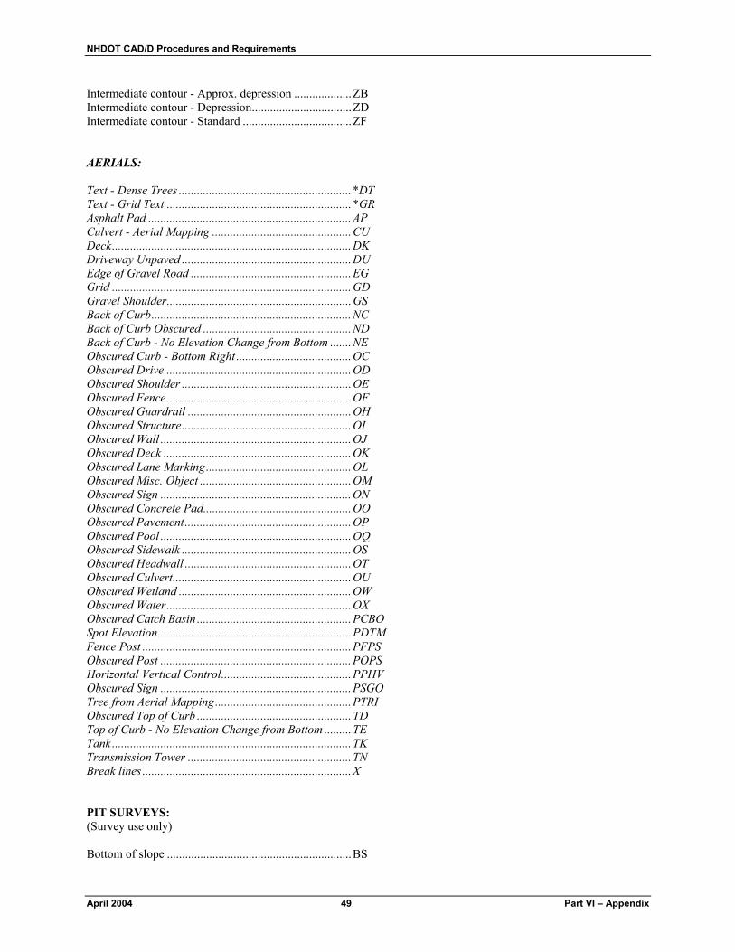
NHDOT CAD/D Procedures and Requirements
April 2004 49 Part VI – Appendix
Intermediate contour - Approx. depression ...................ZB Intermediate contour - Depression.................................ZD Intermediate contour - Standard ....................................ZF AERIALS: Text - Dense Trees .........................................................*DT Text - Grid Text .............................................................*GR Asphalt Pad ...................................................................AP Culvert - Aerial Mapping ..............................................CU Deck...............................................................................DK Driveway Unpaved ........................................................DU Edge of Gravel Road .....................................................EG Grid ...............................................................................GD Gravel Shoulder.............................................................GS Back of Curb..................................................................NC Back of Curb Obscured .................................................ND Back of Curb - No Elevation Change from Bottom .......NE Obscured Curb - Bottom Right ......................................OC Obscured Drive .............................................................OD Obscured Shoulder ........................................................OE Obscured Fence.............................................................OF Obscured Guardrail ......................................................OH Obscured Structure........................................................OI Obscured Wall ...............................................................OJ Obscured Deck ..............................................................OK Obscured Lane Marking................................................OL Obscured Misc. Object ..................................................OM Obscured Sign ...............................................................ON Obscured Concrete Pad.................................................OO Obscured Pavement.......................................................OP Obscured Pool ...............................................................OQ Obscured Sidewalk ........................................................OS Obscured Headwall .......................................................OT Obscured Culvert...........................................................OU Obscured Wetland .........................................................OW Obscured Water.............................................................OX Obscured Catch Basin ...................................................PCBO Spot Elevation................................................................PDTM Fence Post .....................................................................PFPS Obscured Post ...............................................................POPS Horizontal Vertical Control...........................................PPHV Obscured Sign ...............................................................PSGO Tree from Aerial Mapping.............................................PTRI Obscured Top of Curb ...................................................TD Top of Curb - No Elevation Change from Bottom .........TE Tank ...............................................................................TK Transmission Tower ......................................................TN Break lines .....................................................................X PIT SURVEYS: (Survey use only) Bottom of slope .............................................................BS
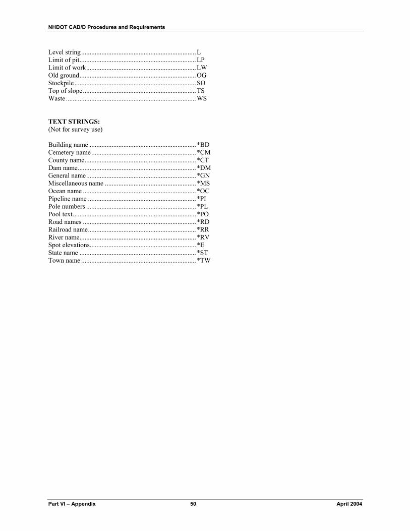
NHDOT CAD/D Procedures and Requirements
Part VI – Appendix 50 April 2004
Level string....................................................................L Limit of pit.....................................................................LP Limit of work.................................................................LW Old ground.....................................................................OG Stockpile ........................................................................SO Top of slope...................................................................TS Waste .............................................................................WS TEXT STRINGS: (Not for survey use) Building name ...............................................................*BD Cemetery name..............................................................*CM County name..................................................................*CT Dam name......................................................................*DM General name.................................................................*GN Miscellaneous name ......................................................*MS Ocean name ...................................................................*OC Pipeline name ................................................................*PI Pole numbers .................................................................*PL Pool text.........................................................................*PO Road names ...................................................................*RD Railroad name................................................................*RR River name.....................................................................*RV Spot elevations...............................................................*E State name .....................................................................*ST Town name ....................................................................*TW
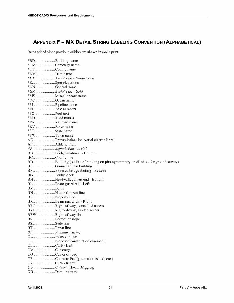
NHDOT CAD/D Procedures and Requirements
April 2004 51 Part VI – Appendix
APPENDIX F – MX DETAIL STRING LABELING CONVENTION (ALPHABETICAL) Items added since previous edition are shown in italic print. *BD ....................Building name *CM....................Cemetery name *CT.....................County name *DM....................Dam name *DT.....................Aerial Text - Dense Trees *E........................Spot elevations *GN ....................General name *GR.....................Aerial Text - Grid *MS ....................Miscellaneous name *OC ....................Ocean name *PI ......................Pipeline name *PL .....................Pole numbers *PO.....................Pool text *RD ....................Road names *RR.....................Railroad name *RV ....................River name *ST .....................State name *TW....................Town name AE.......................Transmission line/Aerial electric lines AF.......................Athletic Field AP .......................Asphalt Pad - Aerial BB.......................Bridge abutment - Bottom BC.......................County line BD ......................Building (outline of building on photogrammetry or sill shots for ground survey) BE.......................Ground at/near building BF .......................Exposed bridge footing - Bottom BG ......................Bridge deck BH ......................Headwall, culvert end - Bottom BL.......................Beam guard rail - Left BM......................Berm BN ......................National forest line BP .......................Property line BR.......................Beam guard rail - Right BRC....................Right-of-way, controlled access BRL ....................Right-of-way, limited access BRW...................Right-of-way line BS .......................Bottom of slope BSL.....................State line BT.......................Town line BY .......................Boundary String C .........................Index contour CE.......................Proposed construction easement CL.......................Curb - Left CM......................Cemetery CO ......................Center of road CP .......................Concrete Pad (gas station island; etc.) CR.......................Curb - Right CU ......................Culvert - Aerial Mapping DB ......................Dam - bottom

NHDOT CAD/D Procedures and Requirements
Part VI – Appendix 52 April 2004
DE.......................Proposed drainage easement DF.......................Double face beam guard rail DK ......................Deck - Aerial DL.......................Ditch line DM......................Dam DP.......................Drainage pipe (Survey: use IGL for dir. shots) DR ......................Driveway DS.......................Magnetic detector sleeve DU ......................Driveway Unpaved - Aerial EG.......................Edge of Gravel Road - Aerial EJB .....................Expansion joint EP .......................Edge of pavement FA.......................Stream or river flow arrow (AERIAL SURVEYS ONLY) FB .......................Fence - Barbed wire FD.......................Foundation/Ruin FM ......................Miscellaneous detail features - Feature string FO.......................Fence - Other GA ......................Gate GD ......................Grid - Aerial GL.......................Cable guard rail - Left GP.......................Gas pumps GR ......................Cable guard rail - Right GS .......................Gravel Shoulder - Aerial HE.......................Hedge HW .....................High water mark JB........................Jersey barrier L..........................Level string LC.......................Street light conduit LF .......................Leachfield LM......................Lane markings LP .......................Limit of pit LW......................Limit of work NC.......................Back of Curb - Aerial ND ......................Obscured Back of Curb - Aerial NE.......................Back of Curb - No Elevation Change from Bottom - Aerial OA ......................Obscured area (aerial surveys) OB ......................Obscured area of bridge (aerial surveys) OC ......................Obscured Curb - Bottom Right - Aerial OD ......................Obscured Drive - Aerial OE.......................Obscured Shoulder - Aerial OF.......................Obscured Fence - Aerial OG ......................Old ground OH ......................Obscured Guardrail - Aerial OI........................Obscured Structure - Aerial OJ .......................Obscured Wall - Aerial OK ......................Obscured Deck - Aerial OL.......................Obscured Lane Marking - Aerial OM......................Obscured Misc. Object - Aerial ON ......................Obscured Sign - Aerial OO ......................Obscured Concrete Pad - Aerial OP.......................Obscured Pavement - Aerial OQ ......................Obscured Pool - Aerial OR ......................Lawn features (flower beds; etc.) OS .......................Obscured Sidewalk - Aerial OT.......................Obscured Headwall - Aerial OU ......................Obscured Culvert - Aerial

NHDOT CAD/D Procedures and Requirements
April 2004 53 Part VI – Appendix
OW......................Obscured Wetland - Aerial OX.......................Obscured Water - Aerial PANC .................Guy wire anchors PBDR..................Boulder PBMK.................Bench mark PBND .................Bound PBOR..................Boring PBTH..................Public telephone PBUS..................Bush PCBD..................Catch basin top PCBO..................Obscured Catch Basin - Aerial PCCT ..................Controller cabinet PCON .................Bound other PDAT..................Satellite dish PDHL..................Drill hole PDID...................Drop inlet top PDTM .................Spot Elevation - Aerial PEBV..................Bridge spot elevations PELV..................Spot Elevations PEVV ..................Spot Elevations - Not at Ground (such as a deck or porch) PFPL...................Flag pole PFPS...................Fence Post - Aerial PFTK ..................Fuel Tank PFTR ..................Fire tower PGAS..................Gas pump PGLT..................Ground light/yard light PGRV .................Gravestone PGSO..................Gas shutoff PGUY .................Guy pole or stub PHHL..................Handhole PHYD .................Fire hydrant PIPN ...................Iron pin or pipe PJCT ...................Utility junction box PJNT...................Joint power and telephone pole PLIT....................Light pole PLPT...................Lamp post/private light pole PLTJ ...................Light on joint pole PLTP...................Light on power pole PMAP .................Mast arm pole PMBF .................Bridge miscellaneous detail features - point string PMBX.................Mail box PMDF .................Miscellaneous detail features - Point string PMHD ................Manhole - Drainage PMHE.................Manhole - Electric PMHG ................Manhole - Gas PMHS .................Manhole - Sewer PMHT.................Manhole - Telephone PMHW................Manhole - Water PMON ................Monuments/statues or other related items POPS ..................Obscured Post - Aerial PPBX..................Pullbox PPHV..................Horizontal Vertical Control - Aerial PPOL ..................Pole PPST...................Post - all types PPTR ..................Transmission line tower PPWR .................Power pole

NHDOT CAD/D Procedures and Requirements
Part VI – Appendix 54 April 2004
PRJM..................Project marker PRSL ..................Railroad signal PRSN..................Railroad sign PRSW .................Railroad switchstand PSGL ..................Traffic signal without mast arm PSGN..................Sign - Single post PSGO..................Obscured Sign - Aerial PSLM..................State line marker PSND..................Sign - Double post PSSA ..................Survey traverse string PSTK ..................Septic Tank PSTP...................Stump PSTT...................Storage tank fill cap PSUM .................Catch basin/Drop inlet sump PSWP..................Swamp symbol PTCS ..................Tree - Coniferous PTDS ..................Tree - Deciduous PTEL ..................Telephone/telegraph pole PTLM .................Town line marker PTRI....................Tree from Aerial Mapping - Aerial PVNT..................Vent pipe - Outlet PWEL .................Well PWGT.................Water gate PWSO.................Water shutoff QP.......................Pool QS.......................Stockpile/lumber pile RD ......................Ridge line RM......................Ramp - Boat; etc. RO ......................Rock outcrop RP .......................Rip-rap RR.......................Railroad RL.......................Retaining wall - Left ---^---^--- RW......................Retaining wall - Right ---v---v--- SC .......................Signal conduit SG.......................Storage tanks SK.......................Sidewalk SL .......................Shore line - Left SD.......................Loop detector SN.......................Sign - Billboard or other large sign (string feature) SO.......................Stockpile SP........................Steps SR .......................Shore line - Right ST .......................Intermittent or small stream SU.......................Sluiceway SW......................Stone wall TB.......................Bridge abutment - Top TC.......................Curb - Top TD.......................Obscured Top of Curb - Aerial TE .......................Top of Curb - No Elevation Change from Bottom - Aerial TF .......................Exposed bridge footing - Top TH.......................Headwall - Top TK .......................Tank - Aerial TL .......................Trail TN .......................Transmission Tower - Aerial TP .......................Top of bridge pier TR.......................Retaining wall - Top

NHDOT CAD/D Procedures and Requirements
April 2004 55 Part VI – Appendix
TS .......................Top of slope TW......................Edge of traveled way UD ......................Underdrain UE.......................Underground Electric UG ......................Underground Gas US.......................Underground Sewer UT.......................Underground Telephone UW .....................Underground Water WA .....................Swamp/marsh or wet area WB......................Wing wall - Bottom WD .....................Delineated wetland WF......................Waterfall WL......................Woods line or brush line - Left WR......................Woods line or brush line - Right WS......................Waste WT......................Wing wall - Top X..........................Break Lines - Aerial Z..........................Intermediate contour

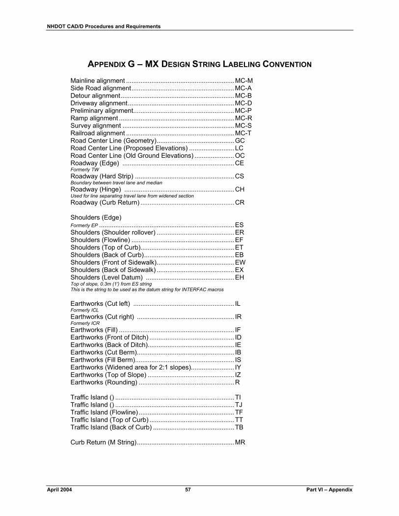
NHDOT CAD/D Procedures and Requirements
April 2004 57 Part VI – Appendix
APPENDIX G – MX DESIGN STRING LABELING CONVENTION Mainline alignment ............................................................MC-M Side Road alignment.........................................................MC-A Detour alignment...............................................................MC-B Driveway alignment...........................................................MC-D Preliminary alignment........................................................MC-P Ramp alignment ................................................................MC-R Survey alignment ..............................................................MC-S Railroad alignment ............................................................MC-T Road Center Line (Geometry)...........................................GC Road Center Line (Proposed Elevations) .........................LC Road Center Line (Old Ground Elevations) ......................OC Roadway (Edge) ..............................................................CE Formerly TW Roadway (Hard Strip) .......................................................CS Boundary between travel lane and median Roadway (Hinge) .............................................................CH Used for line separating travel lane from widened section Roadway (Curb Return) ....................................................CR Shoulders (Edge) Formerly EP ...........................................................................ES Shoulders (Shoulder rollover) ...........................................ER Shoulders (Flowline) .........................................................EF Shoulders (Top of Curb)....................................................ET Shoulders (Back of Curb)..................................................EB Shoulders (Front of Sidewalk)...........................................EW Shoulders (Back of Sidewalk) ...........................................EX Shoulders (Level Datum) .................................................EH Top of slope, 0.3m (1') from ES string This is the string to be used as the datum string for INTERFAC macros Earthworks (Cut left) ........................................................ IL Formerly ICL Earthworks (Cut right) ...................................................... IR Formerly ICR Earthworks (Fill) ................................................................ IF Earthworks (Front of Ditch) ............................................... ID Earthworks (Back of Ditch)................................................ IE Earthworks (Cut Berm)...................................................... IB Earthworks (Fill Berm)....................................................... IS Earthworks (Widened area for 2:1 slopes)........................ IY Earthworks (Top of Slope) ................................................ IZ Earthworks (Rounding) .....................................................R Traffic Island () ..................................................................TI Traffic Island () ..................................................................TJ Traffic Island (Flowline) .....................................................TF Traffic Island (Top of Curb) ...............................................TT Traffic Island (Back of Curb) .............................................TB Curb Return (M String)......................................................MR

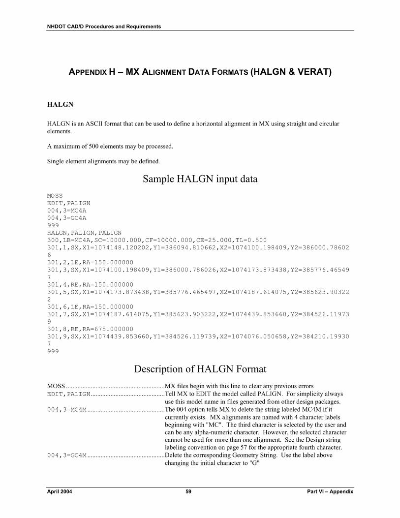
NHDOT CAD/D Procedures and Requirements
April 2004 59 Part VI – Appendix
APPENDIX H – MX ALIGNMENT DATA FORMATS (HALGN & VERAT)
HALGN HALGN is an ASCII format that can be used to define a horizontal alignment in MX using straight and circular elements. A maximum of 500 elements may be processed. Single element alignments may be defined.
Sample HALGN input data MOSS EDIT,PALIGN 004,3=MC4A 004,3=GC4A 999 HALGN,PALIGN,PALIGN 300,LB=MC4A,SC=10000.000,CF=10000.000,CE=25.000,TL=0.500 301,1,SX,X1=1074148.120202,Y1=386094.810662,X2=1074100.198409,Y2=386000.786026 301,2,LE,RA=150.000000 301,3,SX,X1=1074100.198409,Y1=386000.786026,X2=1074173.873438,Y2=385776.465497 301,4,RE,RA=150.000000 301,5,SX,X1=1074173.873438,Y1=385776.465497,X2=1074187.614075,Y2=385623.903222 301,6,LE,RA=150.000000 301,7,SX,X1=1074187.614075,Y1=385623.903222,X2=1074439.853660,Y2=384526.119739 301,8,RE,RA=675.000000 301,9,SX,X1=1074439.853660,Y1=384526.119739,X2=1074076.050658,Y2=384210.199307 999
Description of HALGN Format MOSS ............................................................MX files begin with this line to clear any previous errors EDIT,PALIGN.............................................Tell MX to EDIT the model called PALIGN. For simplicity always
use this model name in files generated from other design packages. 004,3=MC4M ...............................................The 004 option tells MX to delete the string labeled MC4M if it
currently exists. MX alignments are named with 4 character labels beginning with "MC". The third character is selected by the user and can be any alpha-numeric character. However, the selected character cannot be used for more than one alignment. See the Design string labeling convention on page 57 for the appropriate fourth character.
004,3=GC4M ...............................................Delete the corresponding Geometry String. Use the label above changing the initial character to "G"
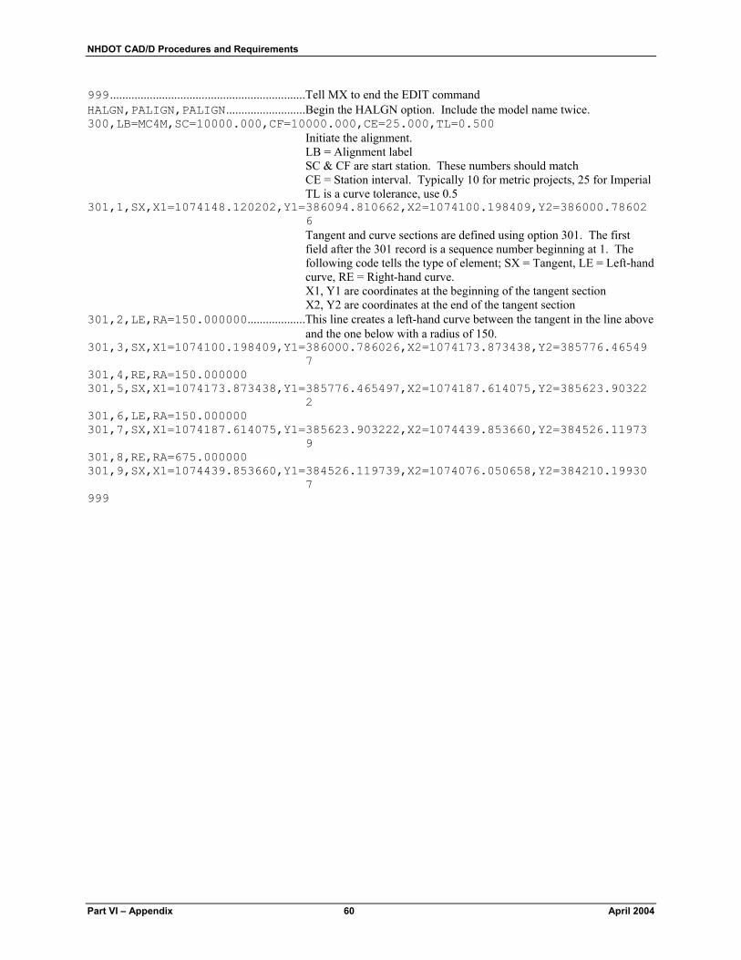
NHDOT CAD/D Procedures and Requirements
Part VI – Appendix 60 April 2004
999................................................................Tell MX to end the EDIT command HALGN,PALIGN,PALIGN..........................Begin the HALGN option. Include the model name twice. 300,LB=MC4M,SC=10000.000,CF=10000.000,CE=25.000,TL=0.500
Initiate the alignment. LB = Alignment label SC & CF are start station. These numbers should match CE = Station interval. Typically 10 for metric projects, 25 for Imperial TL is a curve tolerance, use 0.5
301,1,SX,X1=1074148.120202,Y1=386094.810662,X2=1074100.198409,Y2=386000.786026 Tangent and curve sections are defined using option 301. The first field after the 301 record is a sequence number beginning at 1. The following code tells the type of element; SX = Tangent, LE = Left-hand curve, RE = Right-hand curve. X1, Y1 are coordinates at the beginning of the tangent section X2, Y2 are coordinates at the end of the tangent section
301,2,LE,RA=150.000000...................This line creates a left-hand curve between the tangent in the line above and the one below with a radius of 150.
301,3,SX,X1=1074100.198409,Y1=386000.786026,X2=1074173.873438,Y2=385776.465497
301,4,RE,RA=150.000000 301,5,SX,X1=1074173.873438,Y1=385776.465497,X2=1074187.614075,Y2=385623.90322
2 301,6,LE,RA=150.000000 301,7,SX,X1=1074187.614075,Y1=385623.903222,X2=1074439.853660,Y2=384526.11973
9 301,8,RE,RA=675.000000 301,9,SX,X1=1074439.853660,Y1=384526.119739,X2=1074076.050658,Y2=384210.19930
7 999
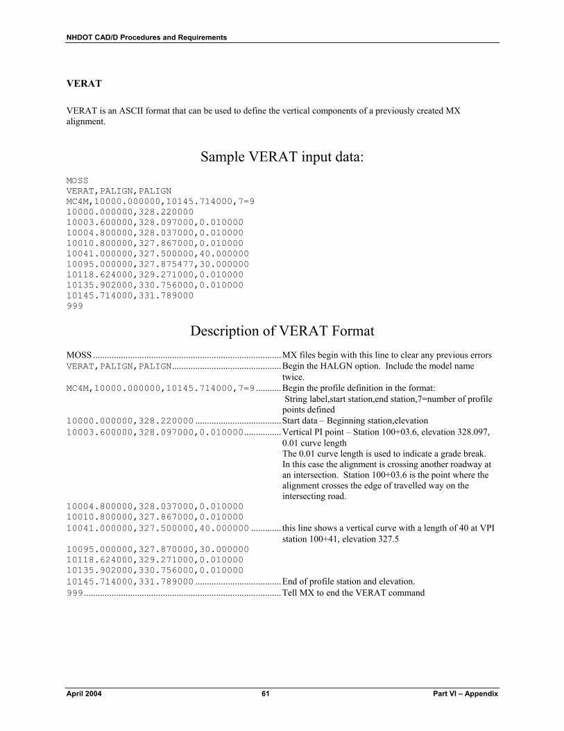
NHDOT CAD/D Procedures and Requirements
April 2004 61 Part VI – Appendix
VERAT VERAT is an ASCII format that can be used to define the vertical components of a previously created MX alignment.
Sample VERAT input data: MOSS VERAT,PALIGN,PALIGN MC4M,10000.000000,10145.714000,7=9 10000.000000,328.220000 10003.600000,328.097000,0.010000 10004.800000,328.037000,0.010000 10010.800000,327.867000,0.010000 10041.000000,327.500000,40.000000 10095.000000,327.875477,30.000000 10118.624000,329.271000,0.010000 10135.902000,330.756000,0.010000 10145.714000,331.789000 999
Description of VERAT Format MOSS .................................................................................MX files begin with this line to clear any previous errors VERAT,PALIGN,PALIGN...............................................Begin the HALGN option. Include the model name
twice. MC4M,10000.000000,10145.714000,7=9 ...........Begin the profile definition in the format:
String label,start station,end station,7=number of profile points defined
10000.000000,328.220000 .....................................Start data – Beginning station,elevation 10003.600000,328.097000,0.010000................Vertical PI point – Station 100+03.6, elevation 328.097,
0.01 curve length The 0.01 curve length is used to indicate a grade break. In this case the alignment is crossing another roadway at an intersection. Station 100+03.6 is the point where the alignment crosses the edge of travelled way on the intersecting road.
10004.800000,328.037000,0.010000 10010.800000,327.867000,0.010000 10041.000000,327.500000,40.000000 ............. this line shows a vertical curve with a length of 40 at VPI
station 100+41, elevation 327.5 10095.000000,327.870000,30.000000 10118.624000,329.271000,0.010000 10135.902000,330.756000,0.010000 10145.714000,331.789000 .....................................End of profile station and elevation. 999.....................................................................................Tell MX to end the VERAT command

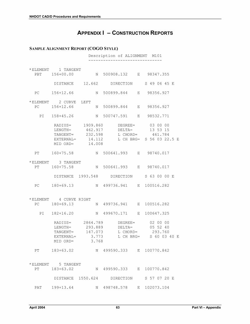
NHDOT CAD/D Procedures and Requirements
April 2004 63 Part VI – Appendix
APPENDIX I – CONSTRUCTION REPORTS
SAMPLE ALIGNMENT REPORT (COGO STYLE) Description of ALIGNMENT M101 ------------------------------
*ELEMENT 1 TANGENT PBT 156+00.00 N 500908.132 E 98347.355 DISTANCE 12.662 DIRECTION S 49 06 45 E PC 156+12.66 N 500899.844 E 98356.927 *ELEMENT 2 CURVE LEFT PC 156+12.66 N 500899.844 E 98356.927 PI 158+45.26 N 500747.591 E 98532.771 RADIUS= 1909.860 DEGREE= 03 00 00 LENGTH= 462.917 DELTA= 13 53 15 TANGENT= 232.598 L CHORD= 461.784 EXTERNAL= 14.112 L CH BRG= S 56 03 22.5 E MID ORD= 14.008 PT 160+75.58 N 500641.993 E 98740.017 *ELEMENT 3 TANGENT PT 160+75.58 N 500641.993 E 98740.017 DISTANCE 1993.548 DIRECTION S 63 00 00 E PC 180+69.13 N 499736.941 E 100516.282 *ELEMENT 4 CURVE RIGHT PC 180+69.13 N 499736.941 E 100516.282 PI 182+16.20 N 499670.171 E 100647.325 RADIUS= 2864.789 DEGREE= 02 00 00 LENGTH= 293.889 DELTA= 05 52 40 TANGENT= 147.073 L CHORD= 293.760 EXTERNAL= 3.773 L CH BRG= S 60 03 40 E MID ORD= 3.768 PT 183+63.02 N 499590.333 E 100770.842 *ELEMENT 5 TANGENT PT 183+63.02 N 499590.333 E 100770.842 DISTANCE 1550.624 DIRECTION S 57 07 20 E PAT 199+13.64 N 498748.578 E 102073.104

NHDOT CAD/D Procedures and Requirements
Part VI – Appendix 64 April 2004
SAMPLE ALIGNMENT REPORT (COORDINATES) Point North East Elevation Station 1 500004.15 99991.85 636.90 70100.00 2 500008.48 99994.35 637.00 70105.00 3 500010.22 99995.36 637.04 70107.01 4 500012.81 99996.85 636.99 70110.00 5 500017.14 99999.35 636.89 70115.00 6 500021.47 100001.85 636.79 70120.00 7 500025.80 100004.35 636.69 70125.00 8 500026.69 100004.86 636.67 70126.02 9 500030.13 100006.85 636.51 70130.00 10 500034.46 100009.35 636.32 70135.00 11 500038.79 100011.85 636.13 70140.00 12 500043.12 100014.35 635.95 70145.00 13 500047.45 100016.85 635.78 70150.00 14 500051.78 100019.35 635.62 70155.00 15 500052.40 100019.71 635.60 70155.72 16 500056.11 100021.85 635.47 70160.00 17 500060.45 100024.34 635.33 70165.00 18 500064.79 100026.83 635.20 70170.00 19 500069.13 100029.31 635.08 70175.00 20 500073.47 100031.79 634.97 70180.00 21 500077.82 100034.26 634.87 70185.00 22 500082.17 100036.72 634.77 70190.00 23 500086.52 100039.18 634.69 70195.00 24 500090.88 100041.63 634.61 70200.00 25 500095.24 100044.08 634.55 70205.00 26 500099.60 100046.52 634.49 70210.00 27 500103.97 100048.95 634.44 70215.00 28 500108.34 100051.38 634.41 70220.00 29 500112.71 100053.81 634.38 70225.00 30 500117.09 100056.23 634.36 70230.00 31 500121.47 100058.64 634.35 70235.00 32 500125.85 100061.04 634.35 70240.00 33 500130.24 100063.45 634.36 70245.00 34 500134.63 100065.84 634.37 70250.00 35 500139.02 100068.23 634.40 70255.00 36 500143.42 100070.61 634.44 70260.00 37 500147.81 100072.99 634.48 70265.00 38 500152.21 100075.36 634.54 70270.00 39 500156.62 100077.73 634.60 70275.00 40 500161.03 100080.09 634.66 70280.00 41 500165.44 100082.45 634.72 70285.00 42 500169.85 100084.80 634.78 70290.00 43 500174.27 100087.14 634.84 70295.00 44 500178.69 100089.48 634.90 70300.00 45 500183.11 100091.81 634.96 70305.00 46 500187.54 100094.13 635.02 70310.00 47 500191.97 100096.45 635.08 70315.00 48 500196.40 100098.77 635.14 70320.00 49 500200.83 100101.08 635.20 70325.00 50 500205.27 100103.38 635.26 70330.00 51 500209.71 100105.68 635.32 70335.00