Embed Size (px)
Citation preview
Entropy 2014 16 5810-5821 doi103390e16115810
entropy ISSN 1099-4300
wwwmdpicomjournalentropy
Article
Choked Flow Characteristics of Subcritical Refrigerant Flowing Through Converging-Diverging Nozzles
Zhenying Zhang 1 Lili Tian 2 Lirui Tong 1 and Yanhua Chen 1
1 Institute of Architecture and Civil Engineering Hebei United University Tangshan 063009 China
E-Mails Tonglr89126com (LT) yhchen72126com (YC) 2 Department of Foreign Languages Tangshan College Tangshan 063000 China
E-Mail lilitian120126com
Author to whom correspondence should be addressed E-Mail zhangzhenyingheuueducn
Tel +86-315-2597-7073
External Editor Kevin H Knuth
Received 10 August 2014 in revised form 17 October 2014 Accepted 29 October 2014
Published 4 November 2014
Abstract This paper presents the experimental results the choked flow characteristics of a
subcritical refrigerant through a converging-diverging nozzle A test nozzle with a throat
diameter of 2 mm was designed and developed The influence of operating conditions on
the choked flow characteristics ie the pressure profile and mass flow rate under choked
flow conditions are investigated The results indicate that the choked flow occurs in the
flow of subcritical refrigerant through nozzles under the normal working conditions of
air-conditioners or heat pumps The pressure drop near the throat is about 80 of the total
pressure drop through the nozzle The critical mass flux is about 19800 ~ 24000
kg(smiddotm2) The critical mass flow rate increases with increasing the upstream pressure and
subcooling Furthermore the relative errors between the model predictions and the
experimental results for the critical mass flux are also presented It is found that the
deviations of the predictions for homogeneous equilibrium model and Henry-Fauske model
from the experimental values are minus35 ~ 5 and 15 ~ 35 respectively
Keywords refrigeration system nozzle choked flow critical mass flow rate
OPEN ACCESS
Entropy 2014 16 5811
1 Introduction
One of the major contributors to the inefficiencies of the basic vapor compression refrigeration
cycle is the throttling loss that results from the isenthalpic expansion from the condensing pressure to
the evaporating pressure in the throttling valve To reduce this loss two phase energy recovery
expanders [1ndash8] or ejectors [9ndash11] replacing the throttling valve have been widely investigated
Flashing flow nozzles are the core part of the impulse turbo expander [12ndash14] or ejector In the
nozzles the potential energy of the incoming high-pressure subcooled or saturated liquid flow is
converted to the kinetic energy of the exiting liquid-vapor flow This behavior is defined as a flashing
acceleration process If the downstream pressure is low enough the liquid will experience a drastic
phase transformation process and the mass flux will not be increased by reducing the downstream
pressure any more ie the choked flashing flow In this circumstance the flow of refrigerant through
the nozzles corresponds to the critical mass flux which is the highest flux that can be achieved by
decreasing the downstream pressure under given upstream conditions To obtain appropriate running
and performance conditions of expansion work recovery devices the flow of refrigerant should be a
choked flow Consequently a deep understanding of the choked flow characteristics of the refrigerant
through a converging-diverging nozzle is very important for the optimum design of the impulse turbo
expanders or ejectors
To the best of the authorsrsquo knowledge studies on refrigerant choked flashing flow through
converging-diverging nozzles are still limited Nakagawa and Takeuchi [15] investigated the effect of
diverging part length on the performance of converging-diverging nozzles for the ejector-expansion
refrigeration cycle using R134a They concluded that the nozzle efficiency increases with the
diverging part length owing to the mechanism that the longer diverging part provides a longer period
of time for the two-phase flow to attain equilibrium Nakagawa and Morimune [16] found that a larger
diverging angle gave a higher nozzle efficiency for two-phase flow of R744
Lucas and Koehler [17] found that choked flashing flow existed inside the motive nozzle during
their experimental process of the R744 ejector expansion refrigeration system Lee et al [18] presented
the experimental results of the R744 ejector expansion refrigeration system and found that the choked
flow appeared when the motive nozzle throat diameter is less than 10 mm but disappeared when the
nozzle throat diameter is over 10 mm Chaiwongsa and Wongwises [19] investigated the effects of
throat diameter of the motive nozzle on the performance of R134a ejector expansion refrigeration
system The motive nozzle throat area of the tested ejector is designed according to the Henry-Fauske
model [20] They found that the heat sink temperature has insignificant effects on the primary mass
flux ie choked flow occurred
Ozaki et al [21] reported that the relative error between homogeneous equilibrium model (HEM) [22]
predictions of the critical nozzle flow rate and their tested data was within 5 in the R744 ejector
expansion refrigeration system Elbel et al [23] investigated the critical mass flux of the converging-
diverging motive nozzle in the R744 ejector expansion refrigeration systems and found that the
deviations of the HEM predictions and the Henry-Fauske model predictions from the experimental
mass flow rates are minus10 ~ minus20 and minus5 ~ minus10 respectively Kornhauser and Harrell [24] found
that the deviations of the experimental mass flow rate values from the HEM predictions are about 10
in their R134a ejector expansion refrigeration systems Pottker et al [25] reported the experimental
Entropy 2014 16 5812
results of the R410A ejector expansion refrigeration system and found that experimental mass flow
rate through the nozzle is lower than Henry-Fauske model prediction but the error was not presented
He et al [26] investigated the effect of inlet subcooling degree on the performance of the converging-
diverging nozzle in the R410A refrigeration experimental system and found that with the increase of
the inlet refrigerant subcooling degree the mass flow rate through the nozzle increased but the nozzle
efficiency decreased
As described above it can be clearly seen that previous published papers have reported the choked
flow characteristics of transcritical R744 through a converging-diverging nozzle However the studies
on subcritical refrigerants inside converging-diverging nozzle have been investigated by only a few
previous research works Especially subcritical refrigerants are extensively used in the air conditioners
and heat pumps at present so the metastability effects might be more significant when subcritical
refrigerants are used as the working fluid The main purpose of the present paper is to study the
subcritical refrigerant choked flow characteristics inside converging-diverging nozzles including
pressure distributions mass flow rate and choked flow model The effects of the relevant parameters
ie upstream pressure downstream pressure and subcooling on pressure distribution and mass flow
rate that have never been presented before are also investigated
2 Experimental Setup
21 Experimental Apparatus and Procedure
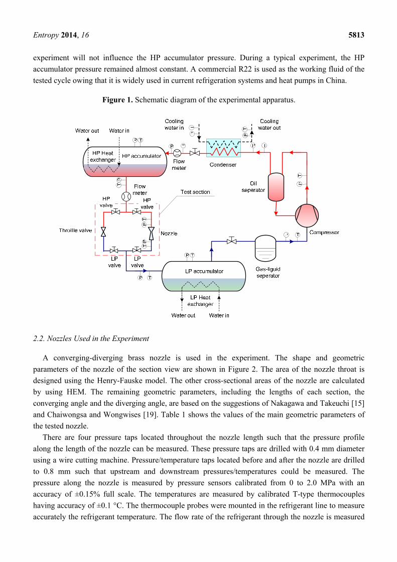
The schematic diagram of the experimental apparatus is shown in Figure 1 The system consisted of
an HP accumulator an LP accumulator a plate heat exchanger (condenser) a compressor and other
accessory parts The compressor is a prototype semi-hermetic reciprocating type compressor The
displacement of the compressor is 847 m3h at 1450 RPM The HP accumulator and LP accumulator
has a volume of 056 m3 An oil separator is used to ensure low oil contamination in the circulating
refrigerant although the oil content is not measured
If the liquid level of the HP accumulator is too low to maintain normal running during the
experiment the HP valve and the LP valve are closed and the other valves are opened The refrigerant
is sucked and compressed by the compressor The high pressure hot vapor discharged by the
compressor is cooled in the condenser The saturated liquid refrigerant then enters the HP accumulator
When the pressure and the liquid level inside the HP accumulator achieve the required conditions the
compressor is powered off
For an experimental run the HP valve and the LP valve through the tested nozzle are opened
whereas other valves are kept closed The high pressure subcooled liquid refrigerant from the HP
accumulator is introduced into the tested converging-diverging nozzle The pressure at the inlet of the
test section (upstream or HP accumulator pressure) is controlled by adjusting the temperature and flow
rate of the water entering the HP heat exchanger After passing through the nozzle the refrigerant
flows into the LP accumulator The pressure at the outlet of the test section (downstream or LP
accumulator pressure) is controlled by adjusting the temperature and flow rate of the chilled water
entering the LP heat exchanger As the flow rate through the nozzle is small and the volume of the HP
accumulator is quite large the amount of liquid removed from the HP accumulator during an
Entropy 2014 16 5813
experiment will not influence the HP accumulator pressure During a typical experiment the HP
accumulator pressure remained almost constant A commercial R22 is used as the working fluid of the
tested cycle owing that it is widely used in current refrigeration systems and heat pumps in China
Figure 1 Schematic diagram of the experimental apparatus
22 Nozzles Used in the Experiment
A converging-diverging brass nozzle is used in the experiment The shape and geometric
parameters of the nozzle of the section view are shown in Figure 2 The area of the nozzle throat is
designed using the Henry-Fauske model The other cross-sectional areas of the nozzle are calculated
by using HEM The remaining geometric parameters including the lengths of each section the
converging angle and the diverging angle are based on the suggestions of Nakagawa and Takeuchi [15]
and Chaiwongsa and Wongwises [19] Table 1 shows the values of the main geometric parameters of
the tested nozzle
There are four pressure taps located throughout the nozzle length such that the pressure profile
along the length of the nozzle can be measured These pressure taps are drilled with 04 mm diameter
using a wire cutting machine Pressuretemperature taps located before and after the nozzle are drilled
to 08 mm such that upstream and downstream pressurestemperatures could be measured The
pressure along the nozzle is measured by pressure sensors calibrated from 0 to 20 MPa with an
accuracy of plusmn015 full scale The temperatures are measured by calibrated T-type thermocouples
having accuracy of plusmn01 degC The thermocouple probes were mounted in the refrigerant line to measure
accurately the refrigerant temperature The flow rate of the refrigerant through the nozzle is measured
Entropy 2014 16 5814
by a Coriolis mass flow meter with an accuracy of plusmn025 full scale (025ndash13 kgmin) All the signals
are treated by a data acquisition instrument
Figure 2 Section view of the tested nozzle
Table 1 Values of the main geometric parameters of the tested nozzle
Parameters Values
Dt (mm) 2 Di (mm) 65 De (mm) 28 Lc (mm) 84 Ld (mm) 229
3 Results and Discussion
31 Pressure Profile
Figure 3 shows the experimental pressure profiles through the nozzle at different downstream
pressures The upstream pressure is kept constant at 17 MPa The upstream subcooling dtsc = tsat minus t
is kept at 5ndash8 degC It is found that the pressure initially decreases slightly in the converging part and
then drops greatly at the throat This behavior implies that the phase change starts near the throat The
noticeable pressure drop near the throat is caused by the mechanism that when the vapor phase appears
in the liquid phase the liquid phase hardly accelerates to match the abrupt increase of the specific
volume When the downstream pressure is less than a certain value the pressures in the diverging part
decrease linearly The variation in downstream pressure has little effect on the pressure profile along
the nozzles ie the change of downstream condition is very little transferred to the upstream Thus it
can be concluded that the choked flow occurs in the flow of subcritical refrigerant through the nozzle
in a normal working condition of air-conditioners or heat pumps When the downstream pressure is
higher than a certain value the pressure in the diverging part initially decreases and then increases
Entropy 2014 16 5815
gradually indicating that a shock wave occurred [27] Increasing the downstream pressure in this
situation leads to the increase of the pressure in the nozzle diverging part
Figure 3 Pressure profiles throughout the nozzle at different downstream pressures
Figure 4 shows the experimental pressure profiles throughout the nozzle for different upstream
pressures The upstream subcooling is kept at 5ndash8 degC The downstream pressure is kept constant at 05
MPa It is found that the increase of upstream pressure causes the pressure at each position along the
nozzle to increase and the pressure drop throughout the nozzle to become higher The pressure drop
throughout the nozzle is about 102 092 091 and 082 MPa at upstream pressures of 17 16 15 and
14 MPa respectively The pressure difference before and after the throat is about 80 of the total
pressure drop through the nozzle
Figure 4 Pressure profiles throughout the nozzle at different upstream pressures
Entropy 2014 16 5816
32 Mass Flow Rate
Figure 5 shows the variations of the experimental mass flow rate with the downstream pressure at
different upstream pressures The upstream subcooling is kept at 5ndash8 degC It can be seen that the mass
flow rate at each upstream pressure initially increases with decreasing downstream pressure but
becomes nearly constant at about 075 MPa It can be deduced that choked flow occurs in the nozzle
This flow behavior is consistent with the results of past research [2829] The maximum mass flow rate
is called the critical mass flow rate It can be seen that the mass flow rate increases with the upstream
pressure The critical mass flow rate increases averagely by about 111 as the upstream pressure is
varied from 15 MPa to 17 MPa This is due to the mechanism whereby the pressure drop through the
nozzle and the density at the nozzle inlet increase The critical mass flux is about 19800~24000
kg(sm2) under the normal working condition of air-conditioners and heat pumps
Figure 5 Effect of downstream pressure on mass flow rate at different upstream pressures
Figure 6 Effect of subcooling on mass flow rate at different upstream pressures
Entropy 2014 16 5817
Figure 6 shows the relationship between the critical mass flow rate and the subcooling at different
upstream pressures The downstream pressure is kept constant at 05 MPa It can be seen that the
critical mass flow rate increases as the subcooling increases showing an increase of about 37ndash74
when the subcooling changes from 3 degC to 10 degC The general trend of mass flow rate versus
subcooling is consistent with the cited literature [26] The density of the refrigerant is increased with
increasing subcooling The delay in vaporization of the refrigerant increases as the subcooling is
increased which leads to the lessening of the flashing vapor generated These two effects lead to the
increase of the critical mass flow rate
HEM [22] and Henry-Fauske model [20] are the two common methods to predict the critical mass
flux of the nozzles Thus the experimental values are compared to the calculated results of the two
models in this paper The choked mass flux prediction of HEM [22] is
1
2 ( ) (1 )c
g lg l
s ss t
v vxx v v x
p p pψ
minus part partpart = minus + minus + minus part part part
(1)
The Henry-Fauske model [20] takes thermodynamic non-equilibrium effects into account Their
iterative set of equations used to determine the critical flux for an initially subcooled liquid is shown in
Equation (2) through Equation (4)
1
20( ) lE
C gE lgE lE t
dsNv v
s s dpψ
minus
= minus minus (2)
0
20
0 21
p
v
p
p clt ψminus= (3)
0 lEEt
gE lE
s sx
s s
minus=minus
(4)
The quantity N describes the partial phase change occurring at the throat It is correlated as a function
of throat equilibrium quality xEt For throat equilibrium qualities greater than 014 N is set equal to
unity Otherwise
014EtN x= (5)
In order to calculate the critical mass flux of the two models the refrigerant temperature and
pressure at the nozzle inlet must be measured The iterations of the two models are started by assuming
a certain throat pressure When combined with the isentropic flow assumption other fluid properties
can be calculated For HEM the throat pressure is iterated until the mass flux reaches a maximum
which is the critical mass flux of the nozzle For Henry-Fauske model the throat pressure is iterated
until the mass fluxes calculated by Equations (2) and (3) are equal This value represents the critical
mass flux which occurs for choked nozzle flow The relative error between the model predictions and
the experimental results for the critical flux is defined as
ex
excal
ψψψε minus= (6)
Entropy 2014 16 5818
where ψcal represents the calculated value by HEM [22] or Henry-Fauske model [20] Figure 7 presents
the values of the relative errors between the model predictions and the experimental results for the
critical mass flux It can be seen that HEM tends to underpredict the critical mass flux which is
consistent with the published literatures [2324] This phenomenon is mainly because the
homogeneous flow assumption neglects possible flashing delays caused by metastability [2829]
which results in the largest possible amount of vapor in the nozzle throat For HEM the discrepancies
between the predicted values and the experimental results for the critical mass flux are in the range of
minus35 ~ 5 for most of the data points The existence of a fraction of positive error is due to the fact
that the upstream refrigerant is almost saturated That is flashing may occur before the refrigerant
flows into the nozzle owing to the pressure loss at the nozzle inlet The Henry-Fauske model
overpredicts the critical mass flux which coincides with the published literature results [25] This is
mainly because the Henry-Fauske model takes the metastability effects of the flashing flow into
account The empirically determined parameter limits the amount of vapor created by flashing during
the rapid expansion process For the Henry-Fauske model the deviations of the predicted values from
the experimental results are between 15 and 35 for most of the investigated data points
Figure 7 Relative errors between model predictions and experimental results
4 Conclusions
This paper presents the experimental results of the choked flow characteristics of a subcritical
refrigerant through a converging-diverging nozzle The influence of operating conditions on the
choked flow characteristics ie the pressure profile and mass flow rate under choked flow conditions
are investigated The results indicate that the choked flow occurs in the flow of a subcritical refrigerant
through the nozzle under the normal working conditions of air-conditioners or heat pumps The
pressure difference before and after the throat is about 80 of the total pressure drop through the
nozzle The critical downstream pressure is about 075 MPa The mass flow rate increases with
increasing the upstream pressure and subcooling Furthermore the relative errors between the model
predictions and the experimental results for the critical mass flux are also presented It is found that the
Entropy 2014 16 5819
deviations of the predictions for HEM and Henry-Fauske model from the experimental values are
minus35 ~ 5 and 15 ~ 35 respectively
Acknowledgments
The authors appreciate the support of Natural Science Foundation of Hebei Province
(No E2014209044 No E2014209089) Tangshan Science and Technology Research Projects
(No 13130299b) and Natural Science Foundation of China (No51378172)
Author Contributions
Zhenying Zhang and Lili Tian did the theoretical work and wrote this paper Lirui Tong and
Yanhua Chen assisted with the editing of the manuscript All authors have read and approved the final
manuscript
Nomenclature
HEM homogeneous equilibrium model
G mass flow rate kgs
N quantity
p pressure MPa
s entropy kJ(kgK)
v specific volume m3kg
x vapor quality
ψ mass flux kg(sm2)
Subscripts
0 stagnation
C critical point
cal calculated value
down downstream
E equilibrium
ex experimental value
g vapor phase
l liquid phase
s isentropic process
sat saturated
sc subcooling
t throat
up upstream
Entropy 2014 16 5820
Conflicts of Interest
The authors declare no conflict of interest
References
1 Zhang Z Ma Y Li M Zhao L Recent advances of energy recovery expanders in the
transcritical CO2 refrigeration cycle HVACampR Res 2013 19 376ndash384
2 Zhang B Peng X He Z Xing Z Shu P Development of a double acting free piston
expander for power recovery in transcritical CO2 cycle Appl Therm Eng 2007 27 1629ndash1636
3 Yang B Peng X Sun S Study of a rotary vane expander for the transcritical CO2 cycle part I
Experimental investigation HVACampR Res 2009 15 673ndash688
4 Yang B Peng X He Z Experimental investigation on the internal working process of a CO2
rotary vane expander Appl Therm Eng 2009 29 2289ndash2296
5 Wang M ZhaoY Cao F Simulation study on a novel vane-type expander with internal two-
stage expansion process for R-410A refrigeration system Int J Refrig 2012 35 757ndash771
6 Nickl J Will G Quack H Integration of a three-stage expander into a CO2 refrigeration
system Int J Refrig 2005 28 1219ndash1224
7 Zhao L Li M Ma Y Liu Z Simulation analysis of a two rolling piston expander replacing
throttling valve in conventional refrigerant heat pump system In Proceedings of the International
Compressor Engineering Conference at Purdue West Lafayette IN USA 16ndash19 July 2012
8 Jia X Zhang B Pu L Improved rotary vane expander for trans-critical CO2 cycle by
introducing high-pressure gas into the vane slots Int J Refrig 2011 34 732ndash741
9 Li D Groll EA Transcritical CO2 refrigeration cycle with ejector-expansion device Int J
Refrig 2005 28 766ndash773
10 Lawrence N Elbel S Theoretical and practical comparison of two-phase ejector refrigeration
cycles including first and second law analysis Int J Refrig 2013 36 1220ndash1232
11 Nakagawa M Marasigan AR Matsukawa T Kurashina A Experimental investigation on the
effect of mixing length on the performance of two-phase ejector for CO2 refrigeration cycle with
and without heat exchanger Int J Refrig 2011 34 1604ndash1613
12 Cho SY Cho CH Kim C Performance characteristics of a turbo expander substituted for
expansion valve on air-conditioner Exp Therm Fluid Sci 2008 32 1655ndash1665
13 Hays LG Brasz JJ Two-phase turbines for compressor energy recovery In Proceedings of
the International Compressor Engineering Conference at Purdue West Lafayette IN USA 23ndash26
July 1996
14 He T Xia C Zhao Y An experimental study on energy recovery by a pelton-type expander in
a domestic refrigeration system HVACampR Res 2009 15 785ndash799
15 Nakagawa M Takeuchi H Performance of two-phase ejector in refrigeration cycle In
Proceedings of the 3rd International Conference on Multiphase Flow Lyon France 8ndash12 June
1998
16 Nakagawa M Morimune Y Subsequent report on nozzle efficiency of two-phase ejector used in
carbon dioxide refrigerator Therm Sci Eng 2003 11 51ndash52
Entropy 2014 16 5821
17 Lucas C Koehler J Experimental investigation of the COP improvement of a refrigeration cycle
by use of an ejector Int J Refrig 2012 35 1595ndash1603
18 Lee JS Kim MS Kim MS Experimental study on the improvement of CO2 air conditioning
system performance using an ejector Int J Refrig 2011 34 1614ndash1625
19 Chaiwongsa P Wongwises S Effect of throat diameters of the ejector on the performance of the
refrigeration cycle using a two-phase ejector as an expansion device Int J Refrig 2007 30 601ndash608
20 Henry RE Fauske HK The two-phase critical flow of one-component mixtures in nozzles
orifices and short tubes J Heat Transf 1971 93 179ndash187
21 Ozaki Y Takeuchi H Hirata T Regeneration of expansion energy by ejector in CO2 cycle In
Proceedings of the 6 th IIR-Gustav Lorentzen Conference on Natural Working Fluids at Glasgow
Glasgow UK 29 Augustndash1 September 2004
22 Starkman E Schrock V Neusen K Maneely D Expansion of a very low quality two-phase
fluid through a convergent-divergent nozzle J Fluids Eng 1964 86 247ndash254
23 Elbel S Historical and present developments of ejector refrigeration systems with emphasis on
transcritical carbon dioxide air-conditioning applications Int J Refrig 2011 34 1545ndash1561
24 Harrell GS Kornhauser AA Performance tests of a two phase ejector In Proceedings of the
30th Intersociety Energy Conversion Engineering Conference (IECEC) Orlando FL USA
30 Julyndash4 August 1995 pp 49ndash53
25 Pottker G Guo B Hrnjak PS Experimental investigation of an R410A vapor compression
system working with an ejector In Proceedings of the International Refrigeration and Air
Conditioning Conference at Purdue West Lafayette IN USA 10ndash11 July 2010
26 He T Xia C Ding L Li L Shu P Influence of subcooling on nozzle efficiency J Xirsquoan
Jiaotong Univ 2009 43 18ndash21
27 Berana MS Nakagawa M Harada A Shock waves in supersonic two-phase flow of CO2 in
converging-diverging nozzles HVACampR Res 2009 15 1081ndash1098
28 Nilpueng K Wongwises S Flow mechanisms of HFC-410A inside short-tube orifices during
flashing process Int J Heat Mass Transf 2010 53 3449ndash3459
29 Singh GM Hrnjak PS Bullard CW Flow of refrigerant R134a through orifice tubes
HVACampR Res 2001 7 245ndash262
copy 2014 by the authors licensee MDPI Basel Switzerland This article is an open access article
distributed under the terms and conditions of the Creative Commons Attribution license
(httpcreativecommonsorglicensesby40)
Entropy 2014 16 5811
1 Introduction
One of the major contributors to the inefficiencies of the basic vapor compression refrigeration
cycle is the throttling loss that results from the isenthalpic expansion from the condensing pressure to
the evaporating pressure in the throttling valve To reduce this loss two phase energy recovery
expanders [1ndash8] or ejectors [9ndash11] replacing the throttling valve have been widely investigated
Flashing flow nozzles are the core part of the impulse turbo expander [12ndash14] or ejector In the
nozzles the potential energy of the incoming high-pressure subcooled or saturated liquid flow is
converted to the kinetic energy of the exiting liquid-vapor flow This behavior is defined as a flashing
acceleration process If the downstream pressure is low enough the liquid will experience a drastic
phase transformation process and the mass flux will not be increased by reducing the downstream
pressure any more ie the choked flashing flow In this circumstance the flow of refrigerant through
the nozzles corresponds to the critical mass flux which is the highest flux that can be achieved by
decreasing the downstream pressure under given upstream conditions To obtain appropriate running
and performance conditions of expansion work recovery devices the flow of refrigerant should be a
choked flow Consequently a deep understanding of the choked flow characteristics of the refrigerant
through a converging-diverging nozzle is very important for the optimum design of the impulse turbo
expanders or ejectors
To the best of the authorsrsquo knowledge studies on refrigerant choked flashing flow through
converging-diverging nozzles are still limited Nakagawa and Takeuchi [15] investigated the effect of
diverging part length on the performance of converging-diverging nozzles for the ejector-expansion
refrigeration cycle using R134a They concluded that the nozzle efficiency increases with the
diverging part length owing to the mechanism that the longer diverging part provides a longer period
of time for the two-phase flow to attain equilibrium Nakagawa and Morimune [16] found that a larger
diverging angle gave a higher nozzle efficiency for two-phase flow of R744
Lucas and Koehler [17] found that choked flashing flow existed inside the motive nozzle during
their experimental process of the R744 ejector expansion refrigeration system Lee et al [18] presented
the experimental results of the R744 ejector expansion refrigeration system and found that the choked
flow appeared when the motive nozzle throat diameter is less than 10 mm but disappeared when the
nozzle throat diameter is over 10 mm Chaiwongsa and Wongwises [19] investigated the effects of
throat diameter of the motive nozzle on the performance of R134a ejector expansion refrigeration
system The motive nozzle throat area of the tested ejector is designed according to the Henry-Fauske
model [20] They found that the heat sink temperature has insignificant effects on the primary mass
flux ie choked flow occurred
Ozaki et al [21] reported that the relative error between homogeneous equilibrium model (HEM) [22]
predictions of the critical nozzle flow rate and their tested data was within 5 in the R744 ejector
expansion refrigeration system Elbel et al [23] investigated the critical mass flux of the converging-
diverging motive nozzle in the R744 ejector expansion refrigeration systems and found that the
deviations of the HEM predictions and the Henry-Fauske model predictions from the experimental
mass flow rates are minus10 ~ minus20 and minus5 ~ minus10 respectively Kornhauser and Harrell [24] found
that the deviations of the experimental mass flow rate values from the HEM predictions are about 10
in their R134a ejector expansion refrigeration systems Pottker et al [25] reported the experimental
Entropy 2014 16 5812
results of the R410A ejector expansion refrigeration system and found that experimental mass flow
rate through the nozzle is lower than Henry-Fauske model prediction but the error was not presented
He et al [26] investigated the effect of inlet subcooling degree on the performance of the converging-
diverging nozzle in the R410A refrigeration experimental system and found that with the increase of
the inlet refrigerant subcooling degree the mass flow rate through the nozzle increased but the nozzle
efficiency decreased
As described above it can be clearly seen that previous published papers have reported the choked
flow characteristics of transcritical R744 through a converging-diverging nozzle However the studies
on subcritical refrigerants inside converging-diverging nozzle have been investigated by only a few
previous research works Especially subcritical refrigerants are extensively used in the air conditioners
and heat pumps at present so the metastability effects might be more significant when subcritical
refrigerants are used as the working fluid The main purpose of the present paper is to study the
subcritical refrigerant choked flow characteristics inside converging-diverging nozzles including
pressure distributions mass flow rate and choked flow model The effects of the relevant parameters
ie upstream pressure downstream pressure and subcooling on pressure distribution and mass flow
rate that have never been presented before are also investigated
2 Experimental Setup
21 Experimental Apparatus and Procedure
The schematic diagram of the experimental apparatus is shown in Figure 1 The system consisted of
an HP accumulator an LP accumulator a plate heat exchanger (condenser) a compressor and other
accessory parts The compressor is a prototype semi-hermetic reciprocating type compressor The
displacement of the compressor is 847 m3h at 1450 RPM The HP accumulator and LP accumulator
has a volume of 056 m3 An oil separator is used to ensure low oil contamination in the circulating
refrigerant although the oil content is not measured
If the liquid level of the HP accumulator is too low to maintain normal running during the
experiment the HP valve and the LP valve are closed and the other valves are opened The refrigerant
is sucked and compressed by the compressor The high pressure hot vapor discharged by the
compressor is cooled in the condenser The saturated liquid refrigerant then enters the HP accumulator
When the pressure and the liquid level inside the HP accumulator achieve the required conditions the
compressor is powered off
For an experimental run the HP valve and the LP valve through the tested nozzle are opened
whereas other valves are kept closed The high pressure subcooled liquid refrigerant from the HP
accumulator is introduced into the tested converging-diverging nozzle The pressure at the inlet of the
test section (upstream or HP accumulator pressure) is controlled by adjusting the temperature and flow
rate of the water entering the HP heat exchanger After passing through the nozzle the refrigerant
flows into the LP accumulator The pressure at the outlet of the test section (downstream or LP
accumulator pressure) is controlled by adjusting the temperature and flow rate of the chilled water
entering the LP heat exchanger As the flow rate through the nozzle is small and the volume of the HP
accumulator is quite large the amount of liquid removed from the HP accumulator during an
Entropy 2014 16 5813
experiment will not influence the HP accumulator pressure During a typical experiment the HP
accumulator pressure remained almost constant A commercial R22 is used as the working fluid of the
tested cycle owing that it is widely used in current refrigeration systems and heat pumps in China
Figure 1 Schematic diagram of the experimental apparatus
22 Nozzles Used in the Experiment
A converging-diverging brass nozzle is used in the experiment The shape and geometric
parameters of the nozzle of the section view are shown in Figure 2 The area of the nozzle throat is
designed using the Henry-Fauske model The other cross-sectional areas of the nozzle are calculated
by using HEM The remaining geometric parameters including the lengths of each section the
converging angle and the diverging angle are based on the suggestions of Nakagawa and Takeuchi [15]
and Chaiwongsa and Wongwises [19] Table 1 shows the values of the main geometric parameters of
the tested nozzle
There are four pressure taps located throughout the nozzle length such that the pressure profile
along the length of the nozzle can be measured These pressure taps are drilled with 04 mm diameter
using a wire cutting machine Pressuretemperature taps located before and after the nozzle are drilled
to 08 mm such that upstream and downstream pressurestemperatures could be measured The
pressure along the nozzle is measured by pressure sensors calibrated from 0 to 20 MPa with an
accuracy of plusmn015 full scale The temperatures are measured by calibrated T-type thermocouples
having accuracy of plusmn01 degC The thermocouple probes were mounted in the refrigerant line to measure
accurately the refrigerant temperature The flow rate of the refrigerant through the nozzle is measured
Entropy 2014 16 5814
by a Coriolis mass flow meter with an accuracy of plusmn025 full scale (025ndash13 kgmin) All the signals
are treated by a data acquisition instrument
Figure 2 Section view of the tested nozzle
Table 1 Values of the main geometric parameters of the tested nozzle
Parameters Values
Dt (mm) 2 Di (mm) 65 De (mm) 28 Lc (mm) 84 Ld (mm) 229
3 Results and Discussion
31 Pressure Profile
Figure 3 shows the experimental pressure profiles through the nozzle at different downstream
pressures The upstream pressure is kept constant at 17 MPa The upstream subcooling dtsc = tsat minus t
is kept at 5ndash8 degC It is found that the pressure initially decreases slightly in the converging part and
then drops greatly at the throat This behavior implies that the phase change starts near the throat The
noticeable pressure drop near the throat is caused by the mechanism that when the vapor phase appears
in the liquid phase the liquid phase hardly accelerates to match the abrupt increase of the specific
volume When the downstream pressure is less than a certain value the pressures in the diverging part
decrease linearly The variation in downstream pressure has little effect on the pressure profile along
the nozzles ie the change of downstream condition is very little transferred to the upstream Thus it
can be concluded that the choked flow occurs in the flow of subcritical refrigerant through the nozzle
in a normal working condition of air-conditioners or heat pumps When the downstream pressure is
higher than a certain value the pressure in the diverging part initially decreases and then increases
Entropy 2014 16 5815
gradually indicating that a shock wave occurred [27] Increasing the downstream pressure in this
situation leads to the increase of the pressure in the nozzle diverging part
Figure 3 Pressure profiles throughout the nozzle at different downstream pressures
Figure 4 shows the experimental pressure profiles throughout the nozzle for different upstream
pressures The upstream subcooling is kept at 5ndash8 degC The downstream pressure is kept constant at 05
MPa It is found that the increase of upstream pressure causes the pressure at each position along the
nozzle to increase and the pressure drop throughout the nozzle to become higher The pressure drop
throughout the nozzle is about 102 092 091 and 082 MPa at upstream pressures of 17 16 15 and
14 MPa respectively The pressure difference before and after the throat is about 80 of the total
pressure drop through the nozzle
Figure 4 Pressure profiles throughout the nozzle at different upstream pressures
Entropy 2014 16 5816
32 Mass Flow Rate
Figure 5 shows the variations of the experimental mass flow rate with the downstream pressure at
different upstream pressures The upstream subcooling is kept at 5ndash8 degC It can be seen that the mass
flow rate at each upstream pressure initially increases with decreasing downstream pressure but
becomes nearly constant at about 075 MPa It can be deduced that choked flow occurs in the nozzle
This flow behavior is consistent with the results of past research [2829] The maximum mass flow rate
is called the critical mass flow rate It can be seen that the mass flow rate increases with the upstream
pressure The critical mass flow rate increases averagely by about 111 as the upstream pressure is
varied from 15 MPa to 17 MPa This is due to the mechanism whereby the pressure drop through the
nozzle and the density at the nozzle inlet increase The critical mass flux is about 19800~24000
kg(sm2) under the normal working condition of air-conditioners and heat pumps
Figure 5 Effect of downstream pressure on mass flow rate at different upstream pressures
Figure 6 Effect of subcooling on mass flow rate at different upstream pressures
Entropy 2014 16 5817
Figure 6 shows the relationship between the critical mass flow rate and the subcooling at different
upstream pressures The downstream pressure is kept constant at 05 MPa It can be seen that the
critical mass flow rate increases as the subcooling increases showing an increase of about 37ndash74
when the subcooling changes from 3 degC to 10 degC The general trend of mass flow rate versus
subcooling is consistent with the cited literature [26] The density of the refrigerant is increased with
increasing subcooling The delay in vaporization of the refrigerant increases as the subcooling is
increased which leads to the lessening of the flashing vapor generated These two effects lead to the
increase of the critical mass flow rate
HEM [22] and Henry-Fauske model [20] are the two common methods to predict the critical mass
flux of the nozzles Thus the experimental values are compared to the calculated results of the two
models in this paper The choked mass flux prediction of HEM [22] is
1
2 ( ) (1 )c
g lg l
s ss t
v vxx v v x
p p pψ
minus part partpart = minus + minus + minus part part part
(1)
The Henry-Fauske model [20] takes thermodynamic non-equilibrium effects into account Their
iterative set of equations used to determine the critical flux for an initially subcooled liquid is shown in
Equation (2) through Equation (4)
1
20( ) lE
C gE lgE lE t
dsNv v
s s dpψ
minus
= minus minus (2)
0
20
0 21
p
v
p
p clt ψminus= (3)
0 lEEt
gE lE
s sx
s s
minus=minus
(4)
The quantity N describes the partial phase change occurring at the throat It is correlated as a function
of throat equilibrium quality xEt For throat equilibrium qualities greater than 014 N is set equal to
unity Otherwise
014EtN x= (5)
In order to calculate the critical mass flux of the two models the refrigerant temperature and
pressure at the nozzle inlet must be measured The iterations of the two models are started by assuming
a certain throat pressure When combined with the isentropic flow assumption other fluid properties
can be calculated For HEM the throat pressure is iterated until the mass flux reaches a maximum
which is the critical mass flux of the nozzle For Henry-Fauske model the throat pressure is iterated
until the mass fluxes calculated by Equations (2) and (3) are equal This value represents the critical
mass flux which occurs for choked nozzle flow The relative error between the model predictions and
the experimental results for the critical flux is defined as
ex
excal
ψψψε minus= (6)
Entropy 2014 16 5818
where ψcal represents the calculated value by HEM [22] or Henry-Fauske model [20] Figure 7 presents
the values of the relative errors between the model predictions and the experimental results for the
critical mass flux It can be seen that HEM tends to underpredict the critical mass flux which is
consistent with the published literatures [2324] This phenomenon is mainly because the
homogeneous flow assumption neglects possible flashing delays caused by metastability [2829]
which results in the largest possible amount of vapor in the nozzle throat For HEM the discrepancies
between the predicted values and the experimental results for the critical mass flux are in the range of
minus35 ~ 5 for most of the data points The existence of a fraction of positive error is due to the fact
that the upstream refrigerant is almost saturated That is flashing may occur before the refrigerant
flows into the nozzle owing to the pressure loss at the nozzle inlet The Henry-Fauske model
overpredicts the critical mass flux which coincides with the published literature results [25] This is
mainly because the Henry-Fauske model takes the metastability effects of the flashing flow into
account The empirically determined parameter limits the amount of vapor created by flashing during
the rapid expansion process For the Henry-Fauske model the deviations of the predicted values from
the experimental results are between 15 and 35 for most of the investigated data points
Figure 7 Relative errors between model predictions and experimental results
4 Conclusions
This paper presents the experimental results of the choked flow characteristics of a subcritical
refrigerant through a converging-diverging nozzle The influence of operating conditions on the
choked flow characteristics ie the pressure profile and mass flow rate under choked flow conditions
are investigated The results indicate that the choked flow occurs in the flow of a subcritical refrigerant
through the nozzle under the normal working conditions of air-conditioners or heat pumps The
pressure difference before and after the throat is about 80 of the total pressure drop through the
nozzle The critical downstream pressure is about 075 MPa The mass flow rate increases with
increasing the upstream pressure and subcooling Furthermore the relative errors between the model
predictions and the experimental results for the critical mass flux are also presented It is found that the
Entropy 2014 16 5819
deviations of the predictions for HEM and Henry-Fauske model from the experimental values are
minus35 ~ 5 and 15 ~ 35 respectively
Acknowledgments
The authors appreciate the support of Natural Science Foundation of Hebei Province
(No E2014209044 No E2014209089) Tangshan Science and Technology Research Projects
(No 13130299b) and Natural Science Foundation of China (No51378172)
Author Contributions
Zhenying Zhang and Lili Tian did the theoretical work and wrote this paper Lirui Tong and
Yanhua Chen assisted with the editing of the manuscript All authors have read and approved the final
manuscript
Nomenclature
HEM homogeneous equilibrium model
G mass flow rate kgs
N quantity
p pressure MPa
s entropy kJ(kgK)
v specific volume m3kg
x vapor quality
ψ mass flux kg(sm2)
Subscripts
0 stagnation
C critical point
cal calculated value
down downstream
E equilibrium
ex experimental value
g vapor phase
l liquid phase
s isentropic process
sat saturated
sc subcooling
t throat
up upstream
Entropy 2014 16 5820
Conflicts of Interest
The authors declare no conflict of interest
References
1 Zhang Z Ma Y Li M Zhao L Recent advances of energy recovery expanders in the
transcritical CO2 refrigeration cycle HVACampR Res 2013 19 376ndash384
2 Zhang B Peng X He Z Xing Z Shu P Development of a double acting free piston
expander for power recovery in transcritical CO2 cycle Appl Therm Eng 2007 27 1629ndash1636
3 Yang B Peng X Sun S Study of a rotary vane expander for the transcritical CO2 cycle part I
Experimental investigation HVACampR Res 2009 15 673ndash688
4 Yang B Peng X He Z Experimental investigation on the internal working process of a CO2
rotary vane expander Appl Therm Eng 2009 29 2289ndash2296
5 Wang M ZhaoY Cao F Simulation study on a novel vane-type expander with internal two-
stage expansion process for R-410A refrigeration system Int J Refrig 2012 35 757ndash771
6 Nickl J Will G Quack H Integration of a three-stage expander into a CO2 refrigeration
system Int J Refrig 2005 28 1219ndash1224
7 Zhao L Li M Ma Y Liu Z Simulation analysis of a two rolling piston expander replacing
throttling valve in conventional refrigerant heat pump system In Proceedings of the International
Compressor Engineering Conference at Purdue West Lafayette IN USA 16ndash19 July 2012
8 Jia X Zhang B Pu L Improved rotary vane expander for trans-critical CO2 cycle by
introducing high-pressure gas into the vane slots Int J Refrig 2011 34 732ndash741
9 Li D Groll EA Transcritical CO2 refrigeration cycle with ejector-expansion device Int J
Refrig 2005 28 766ndash773
10 Lawrence N Elbel S Theoretical and practical comparison of two-phase ejector refrigeration
cycles including first and second law analysis Int J Refrig 2013 36 1220ndash1232
11 Nakagawa M Marasigan AR Matsukawa T Kurashina A Experimental investigation on the
effect of mixing length on the performance of two-phase ejector for CO2 refrigeration cycle with
and without heat exchanger Int J Refrig 2011 34 1604ndash1613
12 Cho SY Cho CH Kim C Performance characteristics of a turbo expander substituted for
expansion valve on air-conditioner Exp Therm Fluid Sci 2008 32 1655ndash1665
13 Hays LG Brasz JJ Two-phase turbines for compressor energy recovery In Proceedings of
the International Compressor Engineering Conference at Purdue West Lafayette IN USA 23ndash26
July 1996
14 He T Xia C Zhao Y An experimental study on energy recovery by a pelton-type expander in
a domestic refrigeration system HVACampR Res 2009 15 785ndash799
15 Nakagawa M Takeuchi H Performance of two-phase ejector in refrigeration cycle In
Proceedings of the 3rd International Conference on Multiphase Flow Lyon France 8ndash12 June
1998
16 Nakagawa M Morimune Y Subsequent report on nozzle efficiency of two-phase ejector used in
carbon dioxide refrigerator Therm Sci Eng 2003 11 51ndash52
Entropy 2014 16 5821
17 Lucas C Koehler J Experimental investigation of the COP improvement of a refrigeration cycle
by use of an ejector Int J Refrig 2012 35 1595ndash1603
18 Lee JS Kim MS Kim MS Experimental study on the improvement of CO2 air conditioning
system performance using an ejector Int J Refrig 2011 34 1614ndash1625
19 Chaiwongsa P Wongwises S Effect of throat diameters of the ejector on the performance of the
refrigeration cycle using a two-phase ejector as an expansion device Int J Refrig 2007 30 601ndash608
20 Henry RE Fauske HK The two-phase critical flow of one-component mixtures in nozzles
orifices and short tubes J Heat Transf 1971 93 179ndash187
21 Ozaki Y Takeuchi H Hirata T Regeneration of expansion energy by ejector in CO2 cycle In
Proceedings of the 6 th IIR-Gustav Lorentzen Conference on Natural Working Fluids at Glasgow
Glasgow UK 29 Augustndash1 September 2004
22 Starkman E Schrock V Neusen K Maneely D Expansion of a very low quality two-phase
fluid through a convergent-divergent nozzle J Fluids Eng 1964 86 247ndash254
23 Elbel S Historical and present developments of ejector refrigeration systems with emphasis on
transcritical carbon dioxide air-conditioning applications Int J Refrig 2011 34 1545ndash1561
24 Harrell GS Kornhauser AA Performance tests of a two phase ejector In Proceedings of the
30th Intersociety Energy Conversion Engineering Conference (IECEC) Orlando FL USA
30 Julyndash4 August 1995 pp 49ndash53
25 Pottker G Guo B Hrnjak PS Experimental investigation of an R410A vapor compression
system working with an ejector In Proceedings of the International Refrigeration and Air
Conditioning Conference at Purdue West Lafayette IN USA 10ndash11 July 2010
26 He T Xia C Ding L Li L Shu P Influence of subcooling on nozzle efficiency J Xirsquoan
Jiaotong Univ 2009 43 18ndash21
27 Berana MS Nakagawa M Harada A Shock waves in supersonic two-phase flow of CO2 in
converging-diverging nozzles HVACampR Res 2009 15 1081ndash1098
28 Nilpueng K Wongwises S Flow mechanisms of HFC-410A inside short-tube orifices during
flashing process Int J Heat Mass Transf 2010 53 3449ndash3459
29 Singh GM Hrnjak PS Bullard CW Flow of refrigerant R134a through orifice tubes
HVACampR Res 2001 7 245ndash262
copy 2014 by the authors licensee MDPI Basel Switzerland This article is an open access article
distributed under the terms and conditions of the Creative Commons Attribution license
(httpcreativecommonsorglicensesby40)
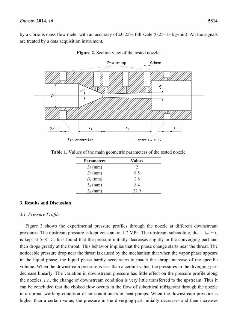
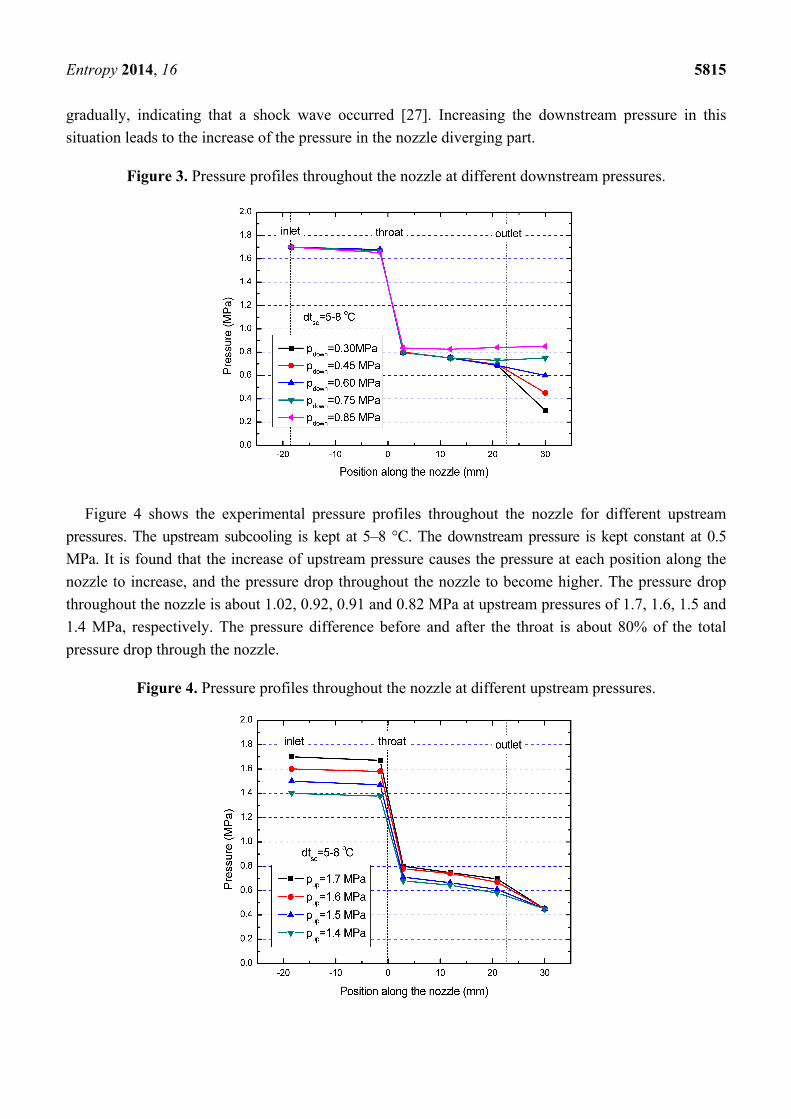
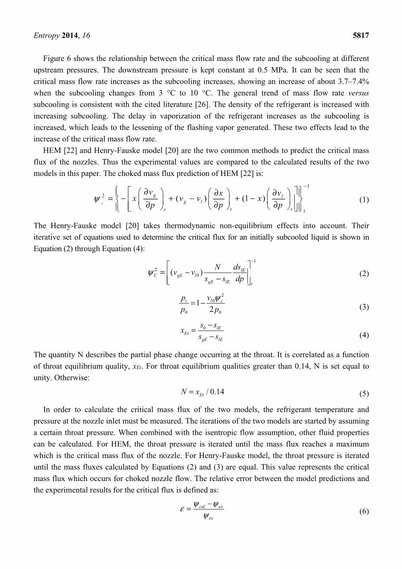
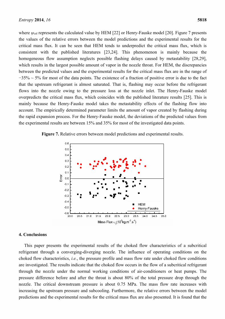


![NUMERICAL SIMULATION OF THE NOZZLE AND EJECTOR … · the ejector diameter had a great influence on the PDE thrust augmentation. Kazuhiko et al. [16] designed a supersonic nozzle](https://img.pdfslide.us/doc/110x75/5e929611ec501b14e15d4fe3/numerical-simulation-of-the-nozzle-and-ejector-the-ejector-diameter-had-a-great.jpg)