Embed Size (px)
Citation preview
RC Business Presentation 1 |
Danfoss Cooling Danfoss Multi Ejector
www.danfoss.com
RC Business Presentation 2 |
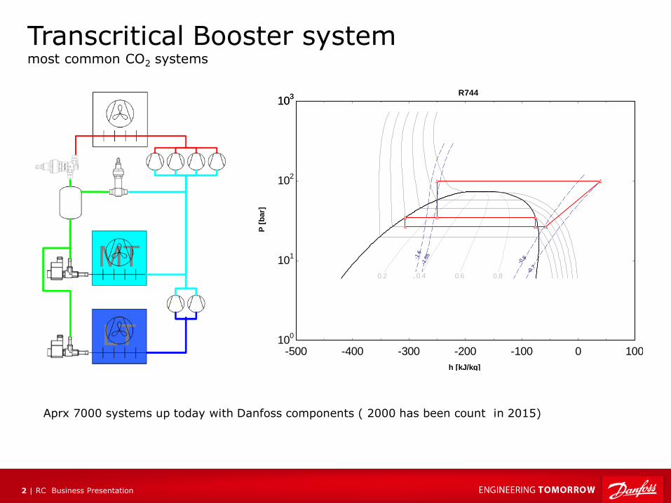
Transcritical Booster system most common CO2 systems
-500 -400 -300 -200 -100 0 10010
0
101
102
103
103
h [kJ/kg]
P [
bar]
0.2 0.4 0.6 0.8
-1.6
-1.5
5
-0.8
-0.7
R744
Aprx 7000 systems up today with Danfoss components ( 2000 has been count in 2015)

RC Business Presentation 3 |
-10%
-5%
0%
5%
10%
15%
20%
25%
30%
25 27 29 31 33 35 37 39 41 43 45
Rela
tive e
nerg
y c
on
su
mp
tio
n t
o R
40
4A
Ambient temperature
Transcritical booster compared to R404A
Above 27oC is not efficient compares to R404A R404A is used as the benchmark for energy and CO2 booster system as benchmark for the swept volume of compressors
Transcritical Booster system Energy comparison
27 °C
RC Business Presentation 4 |
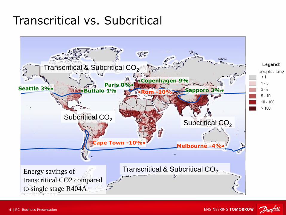
Transcritical vs. Subcritical
Subcritical CO2
Transcritical & Subcritical CO2
Transcritical & Subcritical CO2
Subcritical CO2
Energy savings of
transcritical CO2 compared
to single stage R404A
Melbourne -4%
•Copenhagen 9% Paris 0%
•Rom -10% Seattle 3% Sapporo 3%
Cape Town -10%
•Buffalo 1%
RC Power Point Guideline 5 |
New technologies targeting efficient CO2 systems in warm climate
• Heat reclaim
• Parallel compressions
• Ejectors:
• Vapor ejector in DX system
• Liquid ejector in Flooded system
• Ejectors in flooded system
Evolution of Technology How can we move / remove the CO2 equator?
RC Business Presentation 6 |
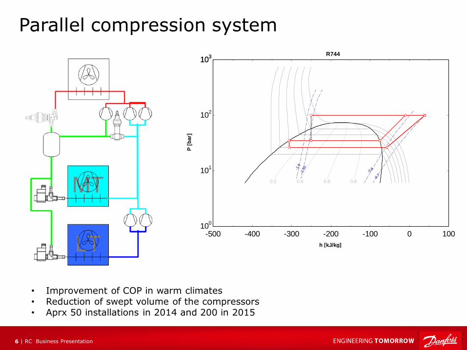
Parallel compression system
-500 -400 -300 -200 -100 0 10010
0
101
102
103
103
h [kJ/kg]
P [
bar]
0.2 0.4 0.6 0.8
-1.6
-1.5
5
-0.8
-0.7
R744
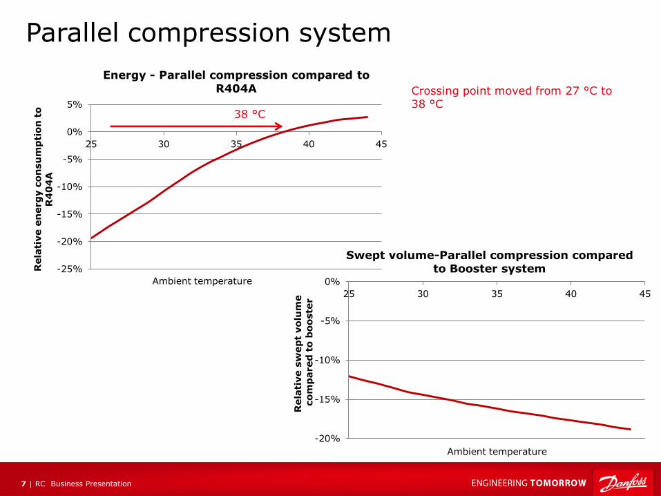
• Improvement of COP in warm climates • Reduction of swept volume of the compressors • Aprx 50 installations in 2014 and 200 in 2015
RC Business Presentation 7 |
-25%
-20%
-15%
-10%
-5%
0%
5%
25 30 35 40 45
Rela
tive e
nerg
y c
on
su
mp
tio
n t
o
R4
04
A
Ambient temperature
Energy - Parallel compression compared to
R404A Crossing point moved from 27 °C to 38 °C
Parallel compression system
-20%
-15%
-10%
-5%
0%
25 30 35 40 45R
ela
tive s
wep
t vo
lum
e
co
mp
ared
to
bo
oste
r
Ambient temperature
Swept volume-Parallel compression compared
to Booster system
38 °C
RC Business Presentation 8 |
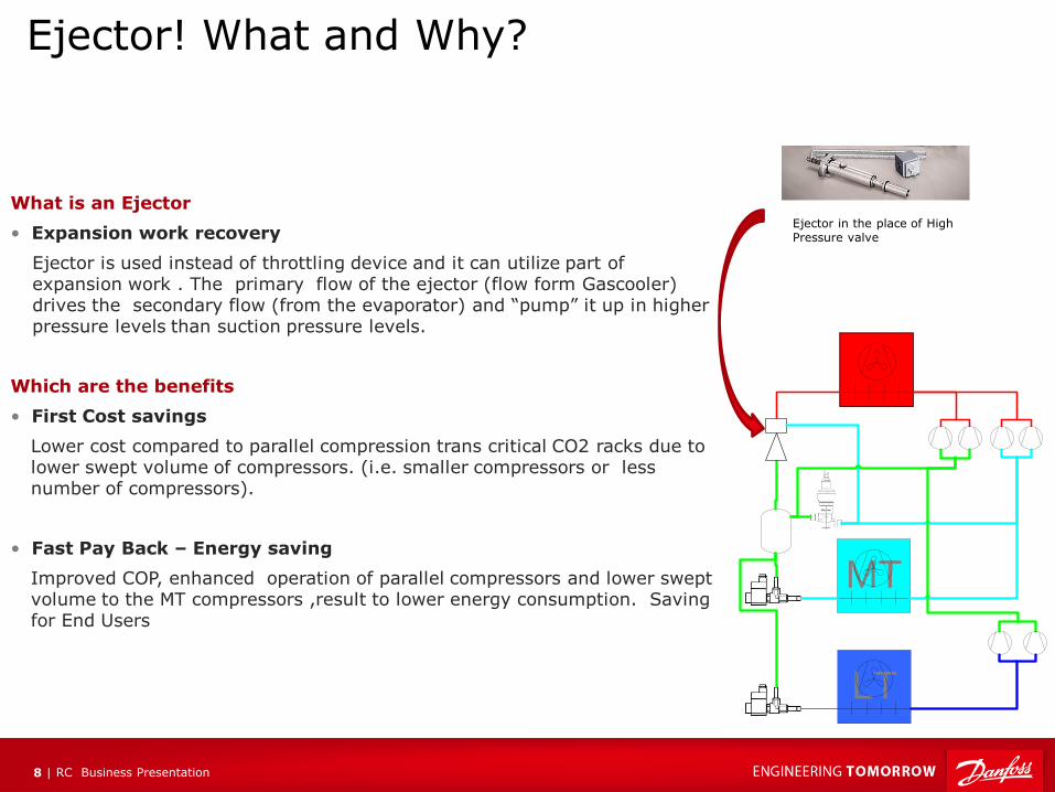
What is an Ejector
• Expansion work recovery
Ejector is used instead of throttling device and it can utilize part of expansion work . The primary flow of the ejector (flow form Gascooler) drives the secondary flow (from the evaporator) and “pump” it up in higher pressure levels than suction pressure levels.
Which are the benefits
• First Cost savings
Lower cost compared to parallel compression trans critical CO2 racks due to lower swept volume of compressors. (i.e. smaller compressors or less number of compressors).
• Fast Pay Back – Energy saving
Improved COP, enhanced operation of parallel compressors and lower swept volume to the MT compressors ,result to lower energy consumption. Saving for End Users
Ejector! What and Why?
MT
LT
Ejector in the place of High Pressure valve
RC Business Presentation 9 |
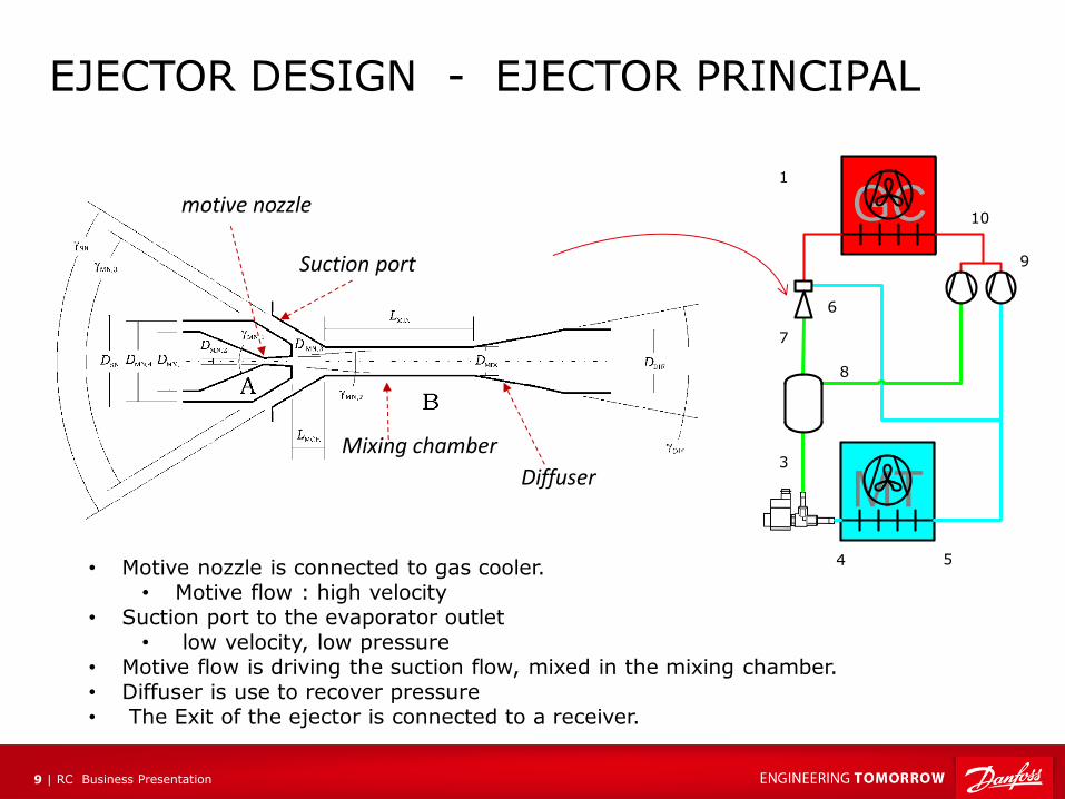
EJECTOR DESIGN - EJECTOR PRINCIPAL
Mixing chamber
motive nozzle
Suction port
Diffuser
GC
MT
1
6
3
4 5
9
10
8
7
• Motive nozzle is connected to gas cooler. • Motive flow : high velocity
• Suction port to the evaporator outlet • low velocity, low pressure
• Motive flow is driving the suction flow, mixed in the mixing chamber. • Diffuser is use to recover pressure • The Exit of the ejector is connected to a receiver.
RC Business Presentation 10 |
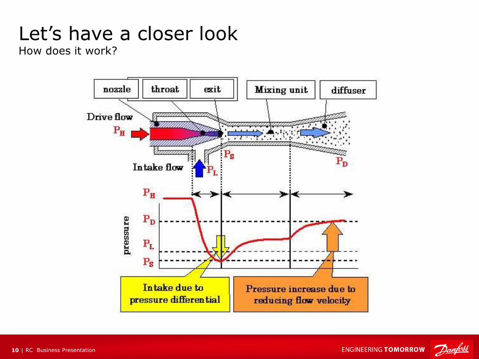
Let’s have a closer look How does it work?
RC Business Presentation 11 |
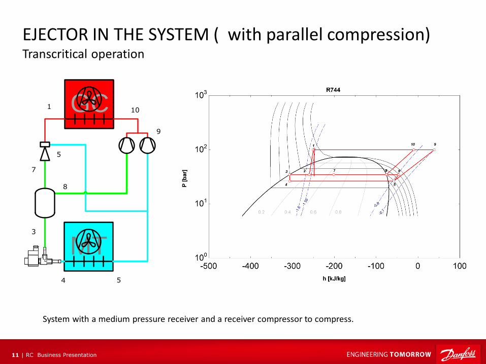
EJECTOR IN THE SYSTEM ( with parallel compression) Transcritical operation
System with a medium pressure receiver and a receiver compressor to compress.
GC
MT
1
5
3
4 5
9
10
8
7

RC Business Presentation 12 |
EJECTOR IN THE SYSTEM ( with parallel compression) Subscritical operation
For ambient temperature is less that 21 oC ejectors are not efficient to pump and the system is operating as a parallel compressor system or a booster system (if receiver compressors are off)
GC
MT
1
5
3
4 5
9
10
8
7
RC Business Presentation 13 |
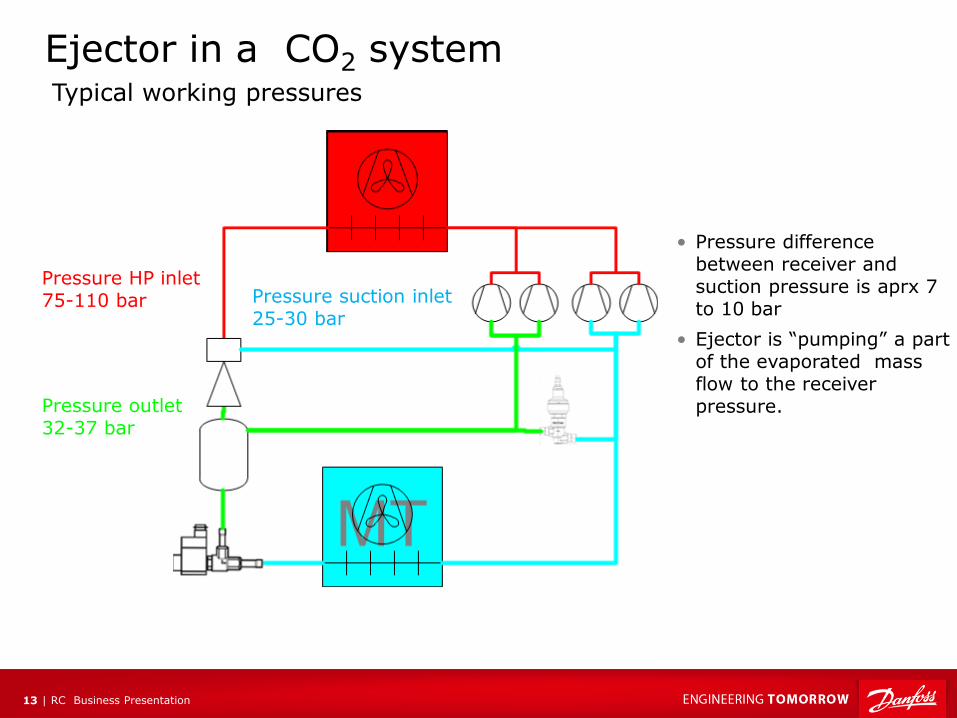
Ejector in a CO2 system
Pressure HP inlet 75-110 bar Pressure suction inlet
25-30 bar
Pressure outlet 32-37 bar
Typical working pressures
• Pressure difference between receiver and suction pressure is aprx 7 to 10 bar
• Ejector is “pumping” a part of the evaporated mass flow to the receiver pressure.
RC Business Presentation 14 |
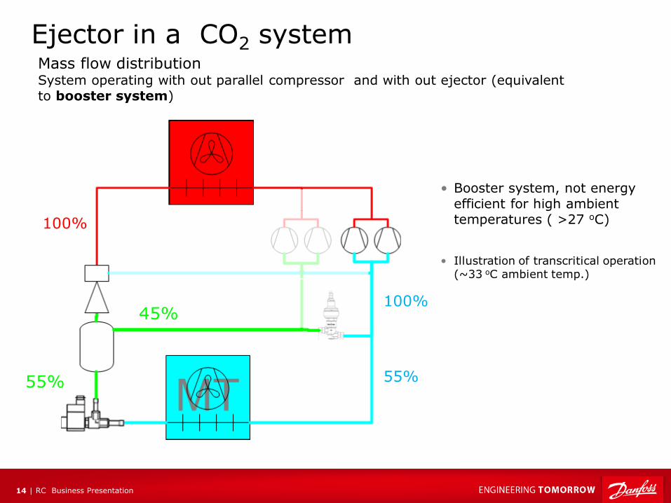
Mass flow distribution System operating with out parallel compressor and with out ejector (equivalent to booster system)
100%
55% 55%
100% 45%
Ejector in a CO2 system
• Booster system, not energy efficient for high ambient temperatures ( >27 oC)
• Illustration of transcritical operation (~33 oC ambient temp.)

RC Business Presentation 15 |
Mass flow distribution System operating with parallel compressor but with out ejectors
100%
55%
55%
45%
Ejector in a CO2 system
• Parallel compressors, compresses gas from a higher start pressure and is therefore delivering a higher COP
• Efficient in higher ambient temperatures
• Illustration of transcritical operation (~33 oC ambient temp.)
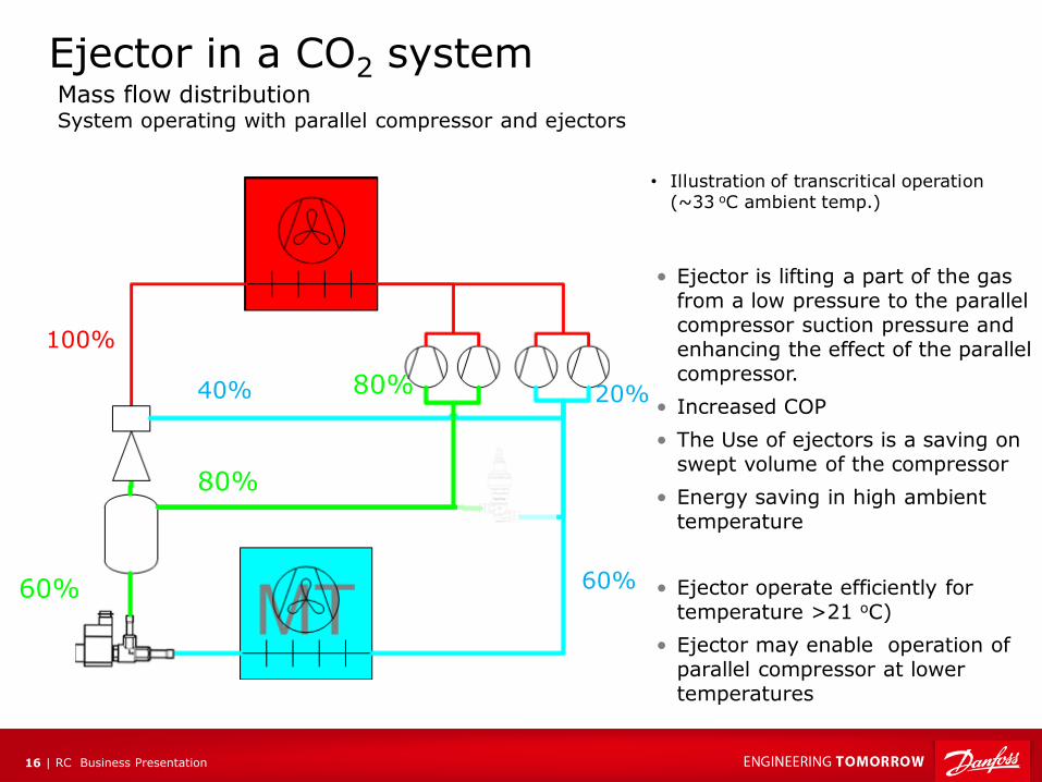
RC Business Presentation 16 |
100%
60% 60%
80%
40% 20%
Ejector in a CO2 system Mass flow distribution System operating with parallel compressor and ejectors
• Ejector is lifting a part of the gas from a low pressure to the parallel compressor suction pressure and enhancing the effect of the parallel compressor.
• Increased COP
• The Use of ejectors is a saving on swept volume of the compressor
• Energy saving in high ambient temperature
• Ejector operate efficiently for temperature >21 oC)
• Ejector may enable operation of parallel compressor at lower temperatures
• Illustration of transcritical operation (~33 oC ambient temp.)
80%
RC Business Presentation 17 |
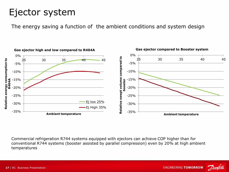
Ejector system
-35%
-30%
-25%
-20%
-15%
-10%
-5%
0%
25 30 35 40 45
Rela
tive e
nerg
y c
on
su
mp
tio
n t
o
R4
04
A
Ambient temperature
Gas ejector high and low compared to R404A
Ej low 25%
Ej High 35%
-35%
-30%
-25%
-20%
-15%
-10%
-5%
0%
25 30 35 40 45
Rela
tive s
wep
t vo
lum
e c
om
pared
to
b
ooste
r
Ambient temperature
Gas ejector compared to Booster system
The energy saving a function of the ambient conditions and system design
Commercial refrigeration R744 systems equipped with ejectors can achieve COP higher than for conventional R744 systems (booster assisted by parallel compression) even by 20% at high ambient temperatures
RC Business Presentation 18 |
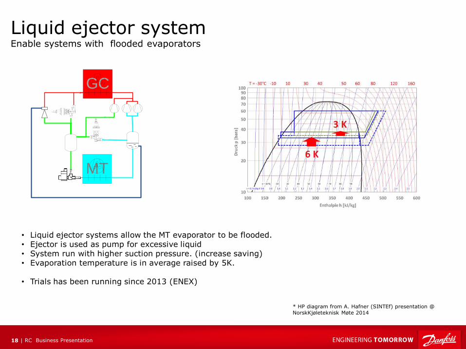
Liquid ejector system Enable systems with flooded evaporators
GC
MT
* HP diagram from A. Hafner (SINTEf) presentation @ NorskKjøleteknisk Møte 2014
• Liquid ejector systems allow the MT evaporator to be flooded. • Ejector is used as pump for excessive liquid • System run with higher suction pressure. (increase saving) • Evaporation temperature is in average raised by 5K.
• Trials has been running since 2013 (ENEX)
RC Business Presentation 19 |
-35%
-30%
-25%
-20%
-15%
-10%
-5%
0%
25 30 35 40 45
Rela
tive s
wep
t vo
lum
e
co
mp
ared
to
bo
oste
r
Ambient temperature
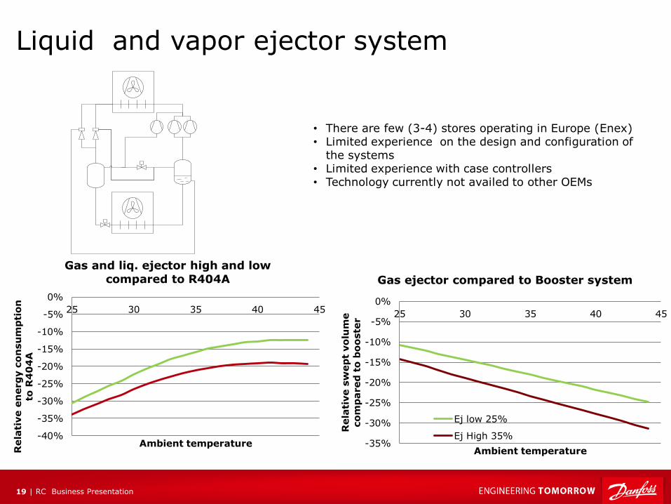
Gas ejector compared to Booster system
Ej low 25%
Ej High 35%-40%
-35%
-30%
-25%
-20%
-15%
-10%
-5%
0%
25 30 35 40 45
Rela
tive e
nerg
y c
on
su
mp
tio
n
to R
40
4A
Ambient temperature
Gas and liq. ejector high and low
compared to R404A
Liquid and vapor ejector system
• There are few (3-4) stores operating in Europe (Enex) • Limited experience on the design and configuration of
the systems • Limited experience with case controllers • Technology currently not availed to other OEMs
RC Business Presentation 20 |
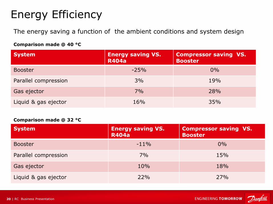
Energy Efficiency
System Energy saving VS. R404a
Compressor saving VS. Booster
Booster -25% 0%
Parallel compression 3% 19%
Gas ejector 7% 28%
Liquid & gas ejector 16% 35%
Comparison made @ 40 °C
The energy saving a function of the ambient conditions and system design
System Energy saving VS. R404a
Compressor saving VS. Booster
Booster -11% 0%
Parallel compression 7% 15%
Gas ejector 10% 18%
Liquid & gas ejector 22% 27%
Comparison made @ 32 °C
RC Business Presentation 21 |
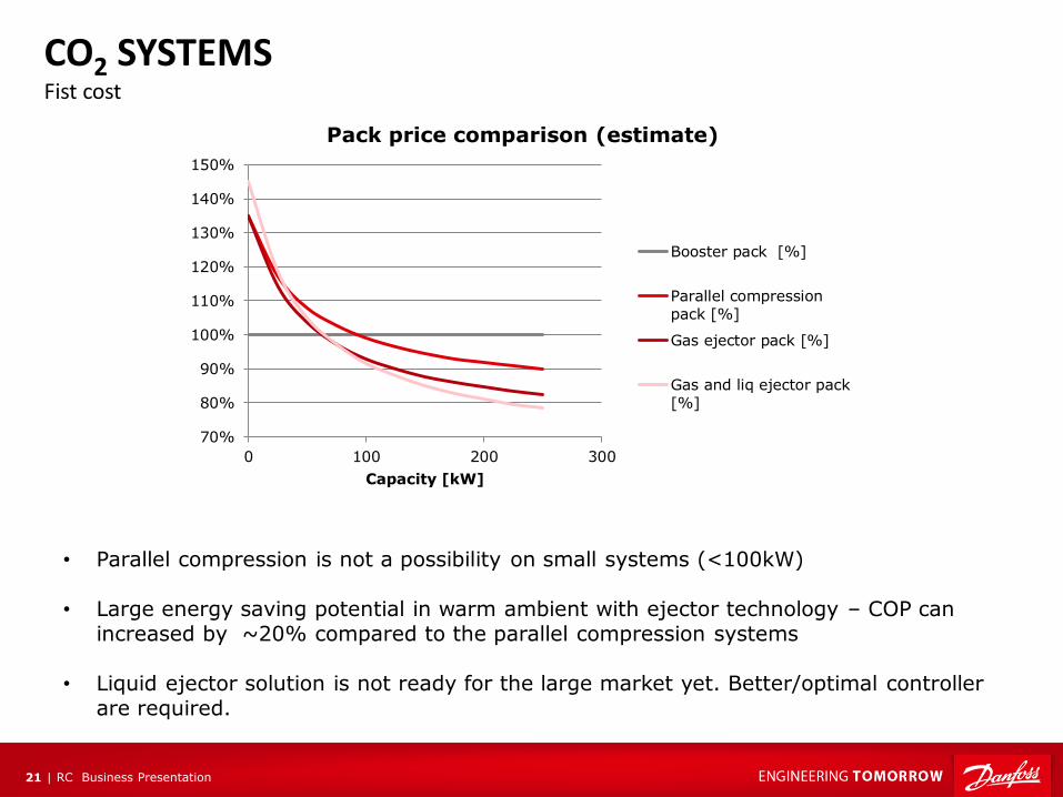
• Parallel compression is not a possibility on small systems (<100kW)
• Large energy saving potential in warm ambient with ejector technology – COP can increased by ~20% compared to the parallel compression systems
• Liquid ejector solution is not ready for the large market yet. Better/optimal controller
are required.
70%
80%
90%
100%
110%
120%
130%
140%
150%
0 100 200 300
Capacity [kW]
Pack price comparison (estimate)
Booster pack [%]
Parallel compressionpack [%]
Gas ejector pack [%]
Gas and liq ejector pack
[%]
CO2 SYSTEMS Fist cost
RC Business Presentation 22 |
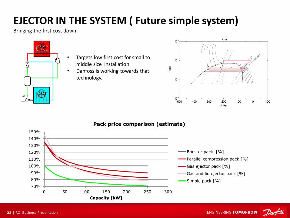
EJECTOR IN THE SYSTEM ( Future simple system) Bringing the first cost down
1
6
• Targets low first cost for small to middle size installation
• Danfoss is working towards that technology.
GC
MT
70%
80%
90%
100%
110%
120%
130%
140%
150%
0 50 100 150 200 250 300
Capacity [kW]
Pack price comparison (estimate)
Booster pack [%]
Parallel compression pack [%]
Gas ejector pack [%]
Gas and liq ejector pack [%]
Simple pack [%]
RC Business Presentation 23 |
Danfoss Multi Ejector