Embed Size (px)
Citation preview
El-O-Matic E and P Series Technical data pneumatic Rack and Pinion actuators
Product Data sheetsDOC.DSE.PN.US Rev. GMay 2011
www.El-O-matic.com
Data sheet
Copyright © Emerson Process Management. The information in this document is subject to change without notice. Updated data sheets can be obtained from our website www.El-O-Matic.com or from your nearest Valve Automation Center USA: +1 813 319 0266 Europe: +31 74 256 10 10 Asia-Pacific: +65 6501 4600
www.El-O-matic.com
Sheet No.: Date: June 2010
A1.102 Rev. B
91.5°
A B
A B
A B
E-series
ED = Double acting ES = Spring return
91.5°
A B
A B
A B
11° Adjustable range*
91° Open
* only standard on E-Serie actuators
-0.5° Closed
91.5°
A B
A B
A B
P-series
PD = Double acting PS = Spring return
TECHNICAL DETAILS, STANDARD ACTUATOR E/P
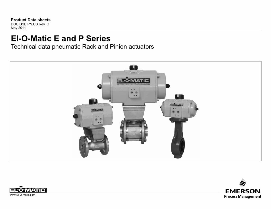
ACTUATOR TYPE E12 E25 E40 E65 E100 E150 E200 E350 E600 E950 E1600 P2500 P4000
Bore inch 1.8 2.2 2.8 3.1 3.6 4.1 4.3 5.7 6.9 7.9 9.1 11.8 12.8Stroke inch 0.5 0.6 0.7 0.9 1.0 1.2 1.5 1.5 1.7 2.0 2.5 2.2 3.2Weight: Double acting lb. 1.3 2.9 4.0 5.3 6.8 10.5 12.8 23 43 58 94 125 191
Spring return lb. 1.5 3.7 5.3 7.9 10.1 15.2 20.1 37 61 85 145 194 291Operating time sec. 0.4 0.5 0.7 1.1 1.2 1.8 2.3 3.6 4.5 5.4 6.9 7 12
Air consumption at 1 atm (cu./in.)
port A stroke 3.1 6.1 9.8 20 21 45 49 110 177 287 445 488 824port B stroke 3.7 6.7 13 22 30 40 61 116 189 299 488 568 1,068
SpecificationPressure range : Double acting 20 to 120 psi : Spring return 80 to 120 psi,, with max. spring set 40 to 120 psi, reduced spring
quantity : 180° actuators 87 psi maximumTorque : 1133 to 40,000 in.lb at 80psi supply
See torque datasheets 1.104.01 and 1.104.02Operating media : Air, dry or lubricated and inert gasses : For sub-zero applications take appropriate measuresTemperature : -4° to +176°FLubrication : Factory lubricated for the normal life of the actuatorConstruction : Suitable for indoor and outdoor installationFinish : Polyester non-TGIC based powder coating
(see data sheet A4.204.01)Rotation : 91.5° (-0.5° CW to 91° CCW)Double acting : Standard counter clockwise with port "A" pressurized
(code A, see data sheet A1.503 for other assembly codes)
Spring return : Clockwise fail action (code A, see data sheet A1.504 for other assembly codes)
Limit stops : Standard on E-series. Adjustable range 91°/80° : Optional on P-series. See datasheet A1.501.01 : For double stroke adjustment. See datasheet
A1.501.05
European DirectivesPED : All actuators are suiteable for use
with Group 2 gasses according to Pressure Equippement Directive 97/23/EC
: Optional : actuators suiteable for use with Group 1 gasses
ATEX : All basic actuators are suiteable for use in hazardous area's classified II 2 GD, zones 1 or 2 (Gasses) and 21 or 22 (Dust)
Russian ApprovalsEl-O-Matic E and P series pneumatic actuators are available with the GOST-R and Rostechnadzor (RTN) approvals.
Note1. Operating time is average with actuator under load
and solenoid valve fitted.2. Air consumption is the actual free air volume at 1 atm.3. Pressure is in barg.
Data sheet
Copyright © Emerson Process Management. The information in this document is subject to change without notice. Updated data sheets can be obtained from our website www.El-O-Matic.com or from your nearest Valve Automation Center USA: +1 813 319 0266 Europe: +31 74 256 10 10 Asia-Pacific: +65 6501 4600
www.El-O-matic.com
Sheet No.: Date: November 2010
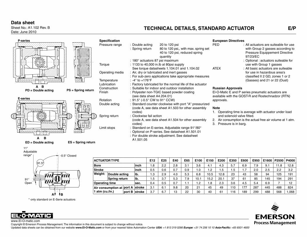
A1.102.10 Rev. C El-O-Matic basic pnEuMatic actuatOr cOnfiguratiOn E/p
single or Double action Es or ps = Single acting, ED or pD = Double acting
actuator sizeE-series0012 = E12 0025 = E25 0040 = E40 0065 = E65 0100 = E100 0150 = E1500200 = E200 0350 = E 350 0600 = E600 0950 = E950 1600 = E1600
P-series2500 = P2500 4000 = P4000
Valve flange Metric Metric UNC/NPT finishISO 5211 DIN 3337 ISO 5211 M = D = u = Standardn = E = V = CSR coating (2 + Aluminum pinionO = f = W = CSR coating (2 + Stainless Steel pinion (3
limit stops0 = No limit stops 1 = L1 One way limit stops 2 = Double Stroke AdjustmentStandard on P-series Standard on E-Series Standard on DSA-Series
assembly codeCode Action Rotation Mountinga = Spring to close clock wise in line with pipelineb = Spring to close clock wise across pipelinec = Spring to open counter clock wise across pipelineD = Spring to open counter clock wise in line with pipeline
spring set E-serie spring set p-serie00 = Double acting actuator 00 = Double acting actuator01 = Springset 1 04 = Springset 4 04 = Springset 4 10 = Springset 1002 = Springset 2 05 = Springset 5 06 = Springset 6 12 = Springset 1203 = Springset 3 06 = Springset 6 08 = Springset 8 14 = Springset 14
future expansiona = Standard
Default insertSize (in mm.) (1 E12 E25 E40 E65 E100 E150 E200 E 350 E600 E950 E1600 P2500 P4000- ISO or UNC 00 11 14 14 19 19 22 27 27 36 46 00 00- DIN 00 11 14 14 17 17 22 22 27 36 46 00 00
Visual indication codeD = Disk K = Knob n = No visual indication
temperature range0 = Standard TS: 80°C (176°F) -20°C ( -4°F)1 = High temp TS: 120°C (248°F) -20°C ( -4°F)2 = Low temp TS: 80°C (176°F) -40°C (-40°F)
Es 0040.M 1 a 05 a.14 n 1(1 Actuators E12, P2500 and P4000 have no inserts. They have have a inner square the shaft 180° actuators are not covered by this configuration matrix.(2 CSR Coating not possible in combination with Double Stroke Adjustment limit stops (DSA series).(3 Stainless Steel Pinion not possible in combination with Double Stroke Adjustment limit stops (DSA series).
see following data sheets for more information
A1.104.01 / A1.104.02
A1.103.106 / A1.103.073 /A1.103.102 / A1.103.103A1.101.30 / A1.101.33 /A4.204.01
A1.501.01/A1.501.05
A1.503/A1.504
A1.104.02
A1.103.073A1.103.106A1.103.120
A1.101.70 / A1.101.71
Data sheetSheet No.: Date: November 2009
Copyright © Emerson Process Management. The information in this document is subject to change without notice. Updated data sheets can be obtained from our website www.El-O-Matic.com or from your nearest Valve Automation Center USA: +1 813 319 0266 Europe: +31 74 256 10 10 Asia-Pacific: +65 6501 4600
www.El-O-matic.com
TM
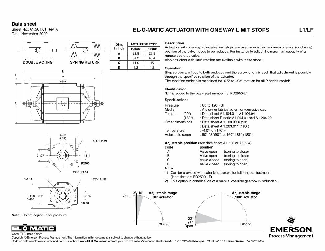
A1.501.01 Rev. A EL-O-MATIC ACTUATOR WITH ONE WAY LIMIT STOPS L1/LF
DescriptionActuators with one way adjustable limit stops are used where the maximum opening (or closing) position of the valve needs to be reduced. For instance to adjust the maximum capacity of a remote operated valve.Also actuators with 180° rotation are available with these stops.
OperationStop screws are fitted to both endcaps and the screw length is such that adjustment is possible through the specified rotation of the actuator.The modified endcap is machined for -0.5° to +93° rotation for all P-series models.
Identification“L1” is added to the basic part number i.e. PD2500-L1
Specification:
Pressure : Up to 120 PSIMedia : Air, dry or lubricated or non-corrosive gasTorque (90°) : Data sheet A1.104.01 - A1.104.04 (180°) : Data sheet P-serie A1.204.01 and A1.204.02Other dimensions : Data sheet A 1.103.XXX (90°) : Data sheet A 1.203.011 (180°)Temperature : -4.0° to +176°FAdjustable range : 80°-93°(90°) or 160°-186° (180°)
Adjustable position (see data sheet A1.503 or A1.504) code position A Valve open (spring to close) B Valve open (spring to close) C Valve closed (spring to open) D Valve closed (spring to open)Note:1) Can be provided with extra long screws for full range adjustment (identification: PD2500-LF)2) This option in combination of a manual override gearbox is redundant
Dim.in inch
ACTUATOR TYPEP2500 P4000
A 22.8 27.9B 31.3 45.4C 14.0 15D 1.2 1.2B
A
C
D
3° 10°Open
Adjustable range 90° actuator
Adjustable range 180° actuator
-20°+6°
Open ClosedClosed
Note: Do not adjust under pressure
B
A
C
D
DOUBLE ACTING SPRING RETURN
9.2366.496
3.827
5/8"-11x.98
P2500
3/4"-10x1.14
1.811
5/8"-11x.98
P4000
2.16510.0006.496
3/4"-
10x1.14
Data sheetSheet No.: Date: November 2009
Copyright © Emerson Process Management. The information in this document is subject to change without notice. Updated data sheets can be obtained from our website www.El-O-Matic.com or from your nearest Valve Automation Center USA: +1 813 319 0266 Europe: +31 74 256 10 10 Asia-Pacific: +65 6501 4600
www.El-O-matic.com
TM
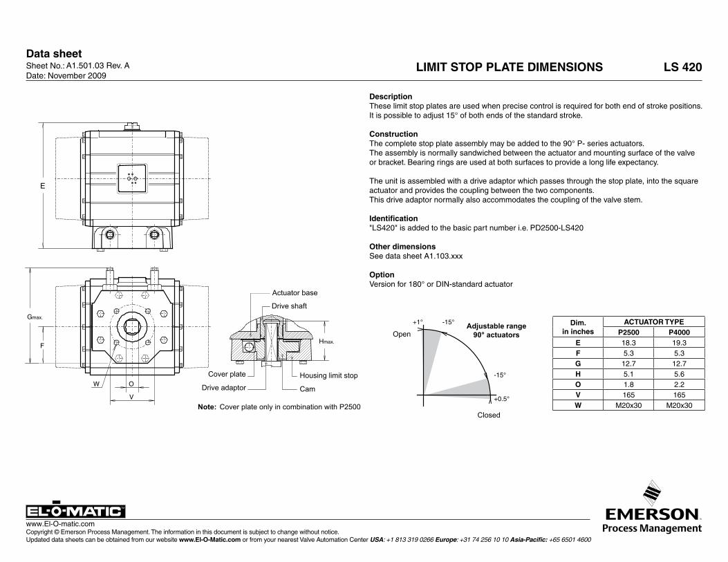
A1.501.03 Rev. A LIMIT STOP PLATE DIMENSIONS LS 420
Dim.in inches
ACTUATOR TYPEP2500 P4000
E 18.3 19.3F 5.3 5.3G 12.7 12.7H 5.1 5.6O 1.8 2.2V 165 165W M20x30 M20x30
DescriptionThese limit stop plates are used when precise control is required for both end of stroke positions.It is possible to adjust 15° of both ends of the standard stroke.
ConstructionThe complete stop plate assembly may be added to the 90° P- series actuators.The assembly is normally sandwiched between the actuator and mounting surface of the valve or bracket. Bearing rings are used at both surfaces to provide a long life expectancy.
The unit is assembled with a drive adaptor which passes through the stop plate, into the square actuator and provides the coupling between the two components.This drive adaptor normally also accommodates the coupling of the valve stem.
Identification"LS420" is added to the basic part number i.e. PD2500-LS420
Other dimensionsSee data sheet A1.103.xxx
OptionVersion for 180° or DIN-standard actuator
+1° -15°
+0.5°
-15°
E
Gmax.
F
W O
V
Hmax.
Drive shaft
Actuator base
Drive adaptor
Cover plate
Cam
Housing limit stop
+1° -15°
+0.5°
-15°
E
Gmax.
F
W O
V
Hmax.
Open
Closed
Adjustable range 90° actuators
Note: Cover plate only in combination with P2500
Data sheetSheet No.: Date: November 2009
Copyright © Emerson Process Management. The information in this document is subject to change without notice. Updated data sheets can be obtained from our website www.El-O-Matic.com or from your nearest Valve Automation Center USA: +1 813 319 0266 Europe: +31 74 256 10 10 Asia-Pacific: +65 6501 4600
www.El-O-matic.com
TM
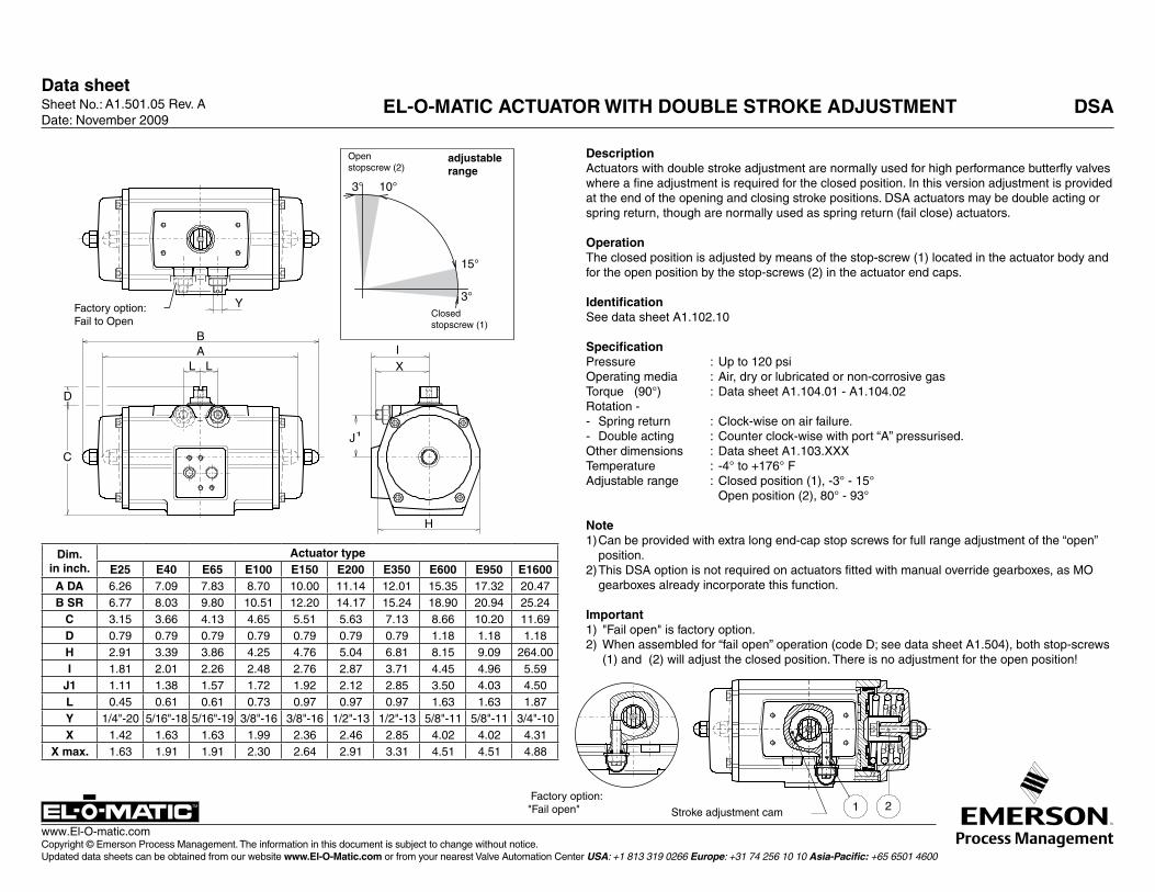
A1.501.05 Rev. A EL-O-MATIC ACTUATOR WITH DOUBLE STROKE ADJUSTMENT DSA
Dim.in inch.
Actuator typeE25 E40 E65 E100 E150 E200 E350 E600 E950 E1600
A DA 6.26 7.09 7.83 8.70 10.00 11.14 12.01 15.35 17.32 20.47B SR 6.77 8.03 9.80 10.51 12.20 14.17 15.24 18.90 20.94 25.24
C 3.15 3.66 4.13 4.65 5.51 5.63 7.13 8.66 10.20 11.69D 0.79 0.79 0.79 0.79 0.79 0.79 0.79 1.18 1.18 1.18H 2.91 3.39 3.86 4.25 4.76 5.04 6.81 8.15 9.09 264.00I 1.81 2.01 2.26 2.48 2.76 2.87 3.71 4.45 4.96 5.59
J1 1.11 1.38 1.57 1.72 1.92 2.12 2.85 3.50 4.03 4.50L 0.45 0.61 0.61 0.73 0.97 0.97 0.97 1.63 1.63 1.87Y 1/4"-20 5/16"-18 5/16"-19 3/8"-16 3/8"-16 1/2"-13 1/2"-13 5/8"-11 5/8"-11 3/4"-10X 1.42 1.63 1.63 1.99 2.36 2.46 2.85 4.02 4.02 4.31
X max. 1.63 1.91 1.91 2.30 2.64 2.91 3.31 4.51 4.51 4.88
Y
AB
C
H
IX
J1
LL
1 2
D
3° 10°
3°
15°
adjustable range
Closedstopscrew (1)
Openstopscrew (2)
Factory option: Fail to Open
Y
AB
C
H
IX
J1
LL
1 2
D
3° 10°
3°
15°
Stroke adjustment cam
Factory option: "Fail open"
DescriptionActuators with double stroke adjustment are normally used for high performance butterfly valves where a fine adjustment is required for the closed position. In this version adjustment is provided at the end of the opening and closing stroke positions. DSA actuators may be double acting or spring return, though are normally used as spring return (fail close) actuators.
OperationThe closed position is adjusted by means of the stop-screw (1) located in the actuator body and for the open position by the stop-screws (2) in the actuator end caps.
IdentificationSee data sheet A1.102.10
SpecificationPressure : Up to 120 psiOperating media : Air, dry or lubricated or non-corrosive gasTorque (90°) : Data sheet A1.104.01 - A1.104.02Rotation -- Spring return : Clock-wise on air failure.- Double acting : Counter clock-wise with port “A” pressurised.Other dimensions : Data sheet A1.103.XXXTemperature : -4° to +176° FAdjustable range : Closed position (1), -3° - 15° Open position (2), 80° - 93°
Note1) Can be provided with extra long end-cap stop screws for full range adjustment of the “open”
position.2) This DSA option is not required on actuators fitted with manual override gearboxes, as MO
gearboxes already incorporate this function.
Important1) "Fail open" is factory option.2) When assembled for “fail open” operation (code D; see data sheet A1.504), both stop-screws
(1) and (2) will adjust the closed position. There is no adjustment for the open position!
Data sheet
Copyright © Emerson Process Management. The information in this document is subject to change without notice. Updated data sheets can be obtained from our website www.El-O-Matic.com or from your nearest Valve Automation Center USA: +1 813 319 0266 Europe: +31 74 256 10 10 Asia-Pacific: +65 6501 4600
www.El-O-matic.com
Sheet No.: Date: May 2011
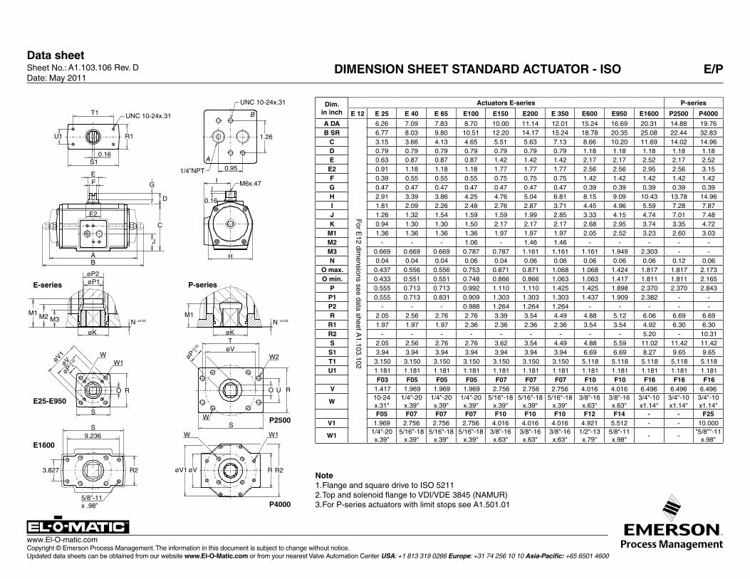
A1.103.106 Rev. D DIMENSION SHEET STANDARD ACTUATOR - ISO E/P
Note1. Flange and square drive to ISO 52112. Top and solenoid flange to VDI/VDE 3845 (NAMUR)3. For P-series actuators with limit stops see A1.501.01
Dim.in inch
Actuators E-series P-series
E 12 E 25 E 40 E 65 E100 E150 E200 E 350 E600 E950 E1600 P2500 P4000
A DA 6.26 7.09 7.83 8.70 10.00 11.14 12.01 15.24 16.69 20.31 14.88 19.76B SR 6.77 8.03 9.80 10.51 12.20 14.17 15.24 18.78 20.35 25.08 22.44 32.83
C 3.15 3.66 4.13 4.65 5.51 5.63 7.13 8.66 10.20 11.69 14.02 14.96D 0.79 0.79 0.79 0.79 0.79 0.79 0.79 1.18 1.18 1.18 1.18 1.18E 0.63 0.87 0.87 0.87 1.42 1.42 1.42 2.17 2.17 2.52 2.17 2.52E2 0.91 1.18 1.18 1.18 1.77 1.77 1.77 2.56 2.56 2.95 2.56 3.15F 0.39 0.55 0.55 0.55 0.75 0.75 0.75 1.42 1.42 1.42 1.42 1.42G 0.47 0.47 0.47 0.47 0.47 0.47 0.47 0.39 0.39 0.39 0.39 0.39H 2.91 3.39 3.86 4.25 4.76 5.04 6.81 8.15 9.09 10.43 13.78 14.96I 1.81 2.09 2.26 2.48 2.76 2.87 3.71 4.45 4.96 5.59 7.28 7.87J 1.26 1.32 1.54 1.59 1.59 1.99 2.85 3.33 4.15 4.74 7.01 7.48K 0.94 1.30 1.30 1.50 2.17 2.17 2.17 2.68 2.95 3.74 3.35 4.72
M1 1.36 1.36 1.36 1.36 1.97 1.97 1.97 2.05 2.52 3.23 2.60 3.03M2 - - - 1.06 - 1.46 1.46 - - - - -M3 0.669 0.669 0.669 0.787 0.787 1.161 1.161 1.161 1.949 2.303 - -N 0.04 0.04 0.04 0.06 0.04 0.06 0.06 0.06 0.06 0.06 0.12 0.06
O max. 0.437 0.556 0.556 0.753 0.871 0.871 1.068 1.068 1.424 1.817 1.817 2.173O min. 0.433 0.551 0.551 0.748 0.866 0.866 1.063 1.063 1.417 1.811 1.811 2.165
P 0.555 0.713 0.713 0.992 1.110 1.110 1.425 1.425 1.898 2.370 2.370 2.843P1 0.555 0.713 0.831 0.909 1.303 1.303 1.303 1.437 1.909 2.382 - -P2 - - - 0.988 1.264 1.264 1.264 - - - - -R 2.05 2.56 2.76 2.76 3.39 3.54 4.49 4.88 5.12 6.06 6.69 6.69R1 1.97 1.97 1.97 2.36 2.36 2.36 2.36 3.54 3.54 4.92 6.30 6.30R2 - - - - - - - - - 5.20 - 10.31S 2.05 2.56 2.76 2.76 3.62 3.54 4.49 4.88 5.59 11.02 11.42 11.42S1 3.94 3.94 3.94 3.94 3.94 3.94 3.94 6.69 6.69 8.27 9.65 9.65T1 3.150 3.150 3.150 3.150 3.150 3.150 3.150 5.118 5.118 5.118 5.118 5.118U1 1.181 1.181 1.181 1.181 1.181 1.181 1.181 1.181 1.181 1.181 1.181 1.181
F03 F05 F05 F05 F07 F07 F07 F10 F10 F16 F16 F16V 1.417 1.969 1.969 1.969 2.756 2.756 2.756 4.016 4.016 6.496 6.496 6.496
W10-24x.31"
1/4"-20 x.39"
1/4"-20 x.39"
1/4"-20 x.39"
5/16"-18 x.39"
5/16"-18 x.39"
5/16"-18 x.39"
3/8"-16 x.63"
3/8"-16 x.63"
3/4"-10 x1.14"
3/4"-10 x1.14"
3/4"-10 x1.14"
F05 F07 F07 F07 F10 F10 F10 F12 F14 - - F25V1 1.969 2.756 2.756 2.756 4.016 4.016 4.016 4.921 5.512 - - 10.000
W11/4"-20 x.39"
5/16"-18 x.39"
5/16"-18 x.39"
5/16"-18 x.39"
3/8"-16 x.63"
3/8"-16 x.63"
3/8"-16 x.63"
1/2"-13 x.79"
5/8"-11 x.98"
- -"5/8""-11
x.98"
F
or E12 dim
ensions see data sheet A1.103.102
R
S
S
R2
øK
W1
M1 M2N ±0.02
øV
O
W
J
AB
øP2øP1
EF G
D
C
E2
H
øK
N ±0.02
øP+0
.02
0 øV
O
WS
R
øV
W1
R R2
T1
U1 R1
S1 A
B
I
øV1
øV1
W
M3
UNC 10-24x.31
0.16
UNC 10-24x.31
1.26
0.951/4”NPT
M6x.47
0.16
E-series
E25-E950
E1600
M1
P-series
P2500
P4000
W2
5/8”-11x .98”
3.827
9.236
øP+0
.02
0
T
U
Data sheetSheet No.: Date: November 2009
Copyright © Emerson Process Management. The information in this document is subject to change without notice. Updated data sheets can be obtained from our website www.El-O-Matic.com or from your nearest Valve Automation Center USA: +1 813 319 0266 Europe: +31 74 256 10 10 Asia-Pacific: +65 6501 4600
www.El-O-matic.com
TM
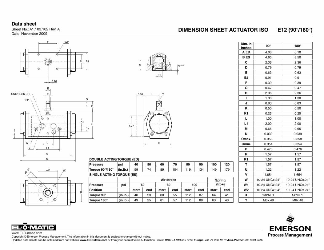
A1.103.102 Rev. A DIMENSION SHEET ACTUATOR ISO E12 (90°/180°)
T W2
U R1
0.16
UNC10-24x .31
1/4"
E
F
G
D
K1
K
C
E2
W1
X
L
L1
A
B
J
øP+0
.02
0 øV
R
W
YI
H
1.77
0.59
M N ±0.02
O
DOUBLE ACTING TORQUE (ED)
Pressure psi 40 50 60 70 80 90 100 120
Torque 90°/180° (in.lb.) 59 74 89 104 119 134 149 179
SINGLE ACTING TORQUE (ES)
Air stroke Spring strokePressure psi 60 80 100
Position - start end start end start end start end
Torque 90° (in.lb.) 48 23 80 55 112 87 64 41
Torque 180° (in.lb.) 49 25 81 57 112 88 63 40
Dim. in Inches
90° 180°
A ED 4.06 6.10
B ES 4.65 8.50
C 2.36 2.36
D 0.79 0.79
E 0.63 0.63
E2 0.91 0.91
F 0.39 0.39
G 0.47 0.47
H 2.36 2.36
I 1.30 1.30
J 0.83 0.83
K 0.50 0.50
K1 0.25 0.25
L 1.00 1.00
L1 2.00 2.00
M 0.65 0.65
N 0.039 0.039
Omax. 0.358 0.358
Omin. 0.354 0.354
P 0.476 0.476
R 1.57 1.57
R1 1.57 1.57
T 1.57 1.57
U 1.22 1.22
V 1.654 1.654
W 10-24 UNCx.24" 10-24 UNCx.24"
W1 10-24 UNCx.24" 10-24 UNCx.24"
W2 10-24 UNCx.24" 10-24 UNCx.24"
X 1/8"NPT 1/8"NPT
Y M6x.48 M6x.48
Data sheet
Copyright © Emerson Process Management. The information in this document is subject to change without notice. Updated data sheets can be obtained from our website www.El-O-Matic.com or from your nearest Valve Automation Center USA: +1 813 319 0266 Europe: +31 74 256 10 10 Asia-Pacific: +65 6501 4600
www.El-O-matic.com
Sheet No.: Date: May 2011
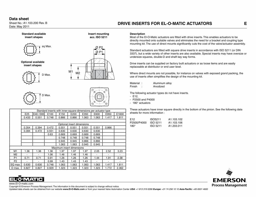
A1.103.200 Rev. B DrivE insErts fOr El-O-Matic actuatOrs E
DescriptionMost of the El-O-Matic actuators are fitted with drive inserts. This enables actuators to be directly mounted onto suitable valves and eliminates the need for a bracket and coupling type mounting kit. The use of direct mounts significantly cuts the cost of the valve/actuator assembly.
Standard actuators are fitted with square drive inserts in accordance with ISO 5211 (or DIN 3337), but a wide variety of other inserts are also available. Special inserts may have oversize or undersize squares, double-D and shaft key way forms.
Drive inserts can be supplied on factory built actuators or as loose items and are easily replaceable at distributor or end user level.
Where direct mounts are not possible, for instance on valves with exposed grand packing, the use of inserts often simplifies the design of the mounting kit.
Material : Aluminum alloyFinish : Anodized
The following actuator types do not have inserts. - E12,- P2500 and P4000 - 180° actuators
These actuators have inner square directly in the bottom of the pinion. See the following data sheets for more information :
E12 ISO5211 A1.103.102P2500/P4000 ISO 5211 A1.103.106180° ISO 5211 A1.203.011
Ø P2Ø P1
M1 M2
standard available insert shapes
insert mountingacc. isO 5211
Optional available insert shapes
sq Max.
D Max.
D Max.
Standard inserts with inner-square-dimensions per actuator typeE25 E40 / E65 E100 E150 E200 E350 E600 E950 E1600
0.433 0.551 0.748 0.866 0.866 1.063 1.063 1.417 1.811
Optional insert dimensions0.354 0.394 0.472 0.551 0.551 0.551 0.551 0.8660.394 0.472 0.551 0.630 0.630 0.630 0.630
0.63 0.669 0.669 0.669 0.6690.748 0.748 0.748 0.7480.945 0.945 0.866 0.8661.063 1.063 0.945 0.945
Maximum insert dimensionsM1 1.36 1.36 1.36 1.97 1.97 1.97 2.05 2.52 3.23M2 - - 1.06 1.46 1.46 1.46 - - -P1 0.71 0.71 0.91 1.26 1.26 1.26 1.44 1.91 2.38P2 - - 0.99 1.43 1.43 1.43 - - -
Sq max. 0.630 0.630 0.748 1.063 1.063 1.063 1.063 1.417 1.811D max. 0.827 0.827 0.929 1.323 1.323 1.323 1.323 1.772 2.362
Data sheetSheet No.: Date: January 2010
Copyright © Emerson Process Management. The information in this document is subject to change without notice. Updated data sheets can be obtained from our website www.El-O-Matic.com or from your nearest Valve Automation Center USA: +1 813 319 0266 Europe: +31 74 256 10 10 Asia-Pacific: +65 6501 4600
www.El-O-matic.com
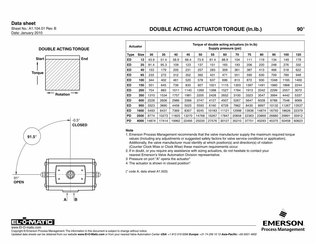
A1.104.01 Rev. B DOUBLE ACTING ACTUATOR TORQUE (In.lb.) 90°
ActuatorTorque of double acting actuators (in In.lb)
Supply pressure (psi)
Type Size 30 35 40 45 50 55 60 70 75 80 90 100 120
ED 12 43.9 51.4 58.9 66.4 73.9 81.4 88.9 104 111 119 134 149 179
ED 25 81.4 95.3 109 123 137 151 165 193 206 220 248 276 332
ED 40 153 179 205 231 257 283 309 361 387 413 466 518 622
ED 65 233 272 312 352 392 431 471 551 590 630 709 789 948
ED 100 344 402 461 520 578 637 696 813 872 930 1048 1165 1400
ED 150 551 645 739 833 927 1021 1115 1303 1397 1491 1680 1868 2244
ED 200 754 883 1011 1140 1269 1398 1527 1784 1913 2042 2299 2557 3072
ED 350 1310 1534 1757 1981 2205 2428 2652 3100 3323 3547 3994 4442 5337
ED 600 2226 2606 2986 3366 3747 4127 4507 5267 5647 6028 6788 7548 9069
ED 950 3323 3890 4458 5025 5593 6160 6728 7862 8430 8997 10132 11267 13537
ED 1600 5493 6431 7369 8307 9245 10183 11121 12998 13936 14874 16750 18626 22379
PD 2500 8774 10273 11825 13270 14768 16267 17847 20858 22363 23869 26880 29891 35912
PD 4000 14874 17414 19962 22495 25035 27576 30127 35210 37751 40293 45375 50458 60623
Note1. Emerson Process Management recommends that the valve manufacturer supply the maximum required torque
values (Including any adjustments or suggested safety factors for valve service conditions or application). Additionally, the valve manufacturer must identify at which position(s) and direction(s) of rotation
(Counter Clock Wise or Clock Wise) these maximum requirements occur. 2. If in doubt, or you require any assistance with sizing actuators, do not hesitate to contact your
nearest Emerson's Valve Automation Division representative.3 Pressure on port "A" opens the actuator*4 The actuator is shown in closed position*
(* code A, data sheet A1.503)
91.5°
-0.5°
91°
A B
CLOSED
OPEN
Rotation
Start End
Torque
DOUBLE ACTING TORQUE
Data sheetSheet No.: Date: January 2010
Copyright © Emerson Process Management. The information in this document is subject to change without notice. Updated data sheets can be obtained from our website www.El-O-Matic.com or from your nearest Valve Automation Center USA: +1 813 319 0266 Europe: +31 74 256 10 10 Asia-Pacific: +65 6501 4600
www.El-O-matic.com
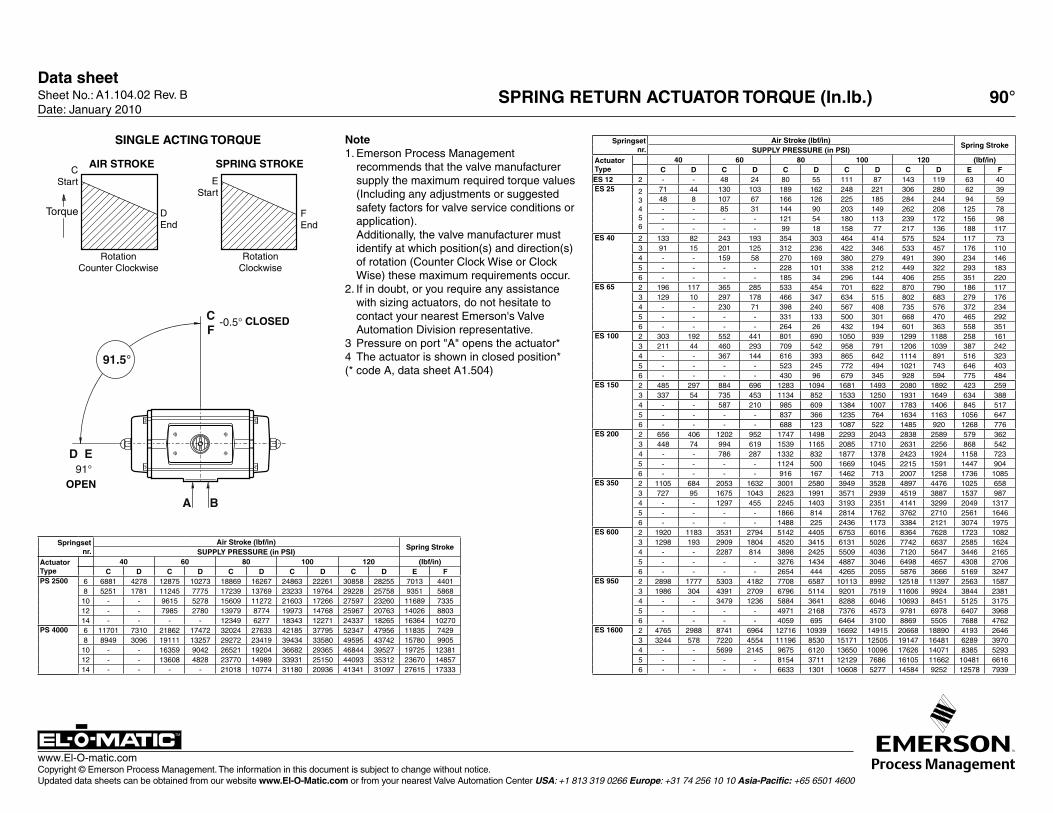
A1.104.02 Rev. B SPRING RETURN ACTUATOR TORQUE (In.lb.) 90°
Springsetnr.
Air Stroke (lbf/in)Spring Stroke
SUPPLY PRESSURE (in PSI)ActuatorType
40 60 80 100 120 (lbf/in)C D C D C D C D C D E F
ES 12 2 - - 48 24 80 55 111 87 143 119 63 40ES 25 2
3 4 5 6
71 44 130 103 189 162 248 221 306 280 62 3948 8 107 67 166 126 225 185 284 244 94 59- - 85 31 144 90 203 149 262 208 125 78- - - - 121 54 180 113 239 172 156 98- - - - 99 18 158 77 217 136 188 117
ES 40 2 133 82 243 193 354 303 464 414 575 524 117 733 91 15 201 125 312 236 422 346 533 457 176 1104 - - 159 58 270 169 380 279 491 390 234 1465 - - - - 228 101 338 212 449 322 293 1836 - - - - 185 34 296 144 406 255 351 220
ES 65 2 196 117 365 285 533 454 701 622 870 790 186 1173 129 10 297 178 466 347 634 515 802 683 279 1764 - - 230 71 398 240 567 408 735 576 372 2345 - - - - 331 133 500 301 668 470 465 2926 - - - - 264 26 432 194 601 363 558 351
ES 100 2 303 192 552 441 801 690 1050 939 1299 1188 258 1613 211 44 460 293 709 542 958 791 1206 1039 387 2424 - - 367 144 616 393 865 642 1114 891 516 3235 - - - - 523 245 772 494 1021 743 646 4036 - - - - 430 96 679 345 928 594 775 484
ES 150 2 485 297 884 696 1283 1094 1681 1493 2080 1892 423 2593 337 54 735 453 1134 852 1533 1250 1931 1649 634 3884 - - 587 210 985 609 1384 1007 1783 1406 845 5175 - - - - 837 366 1235 764 1634 1163 1056 6476 - - - - 688 123 1087 522 1485 920 1268 776
ES 200 2 656 406 1202 952 1747 1498 2293 2043 2838 2589 579 3623 448 74 994 619 1539 1165 2085 1710 2631 2256 868 5424 - - 786 287 1332 832 1877 1378 2423 1924 1158 7235 - - - - 1124 500 1669 1045 2215 1591 1447 9046 - - - - 916 167 1462 713 2007 1258 1736 1085
ES 350 2 1105 684 2053 1632 3001 2580 3949 3528 4897 4476 1025 6583 727 95 1675 1043 2623 1991 3571 2939 4519 3887 1537 9874 - - 1297 455 2245 1403 3193 2351 4141 3299 2049 13175 - - - - 1866 814 2814 1762 3762 2710 2561 16466 - - - - 1488 225 2436 1173 3384 2121 3074 1975
ES 600 2 1920 1183 3531 2794 5142 4405 6753 6016 8364 7628 1723 10823 1298 193 2909 1804 4520 3415 6131 5026 7742 6637 2585 16244 - - 2287 814 3898 2425 5509 4036 7120 5647 3446 21655 - - - - 3276 1434 4887 3046 6498 4657 4308 27066 - - - - 2654 444 4265 2055 5876 3666 5169 3247
ES 950 2 2898 1777 5303 4182 7708 6587 10113 8992 12518 11397 2563 15873 1986 304 4391 2709 6796 5114 9201 7519 11606 9924 3844 23814 - - 3479 1236 5884 3641 8288 6046 10693 8451 5125 31755 - - - - 4971 2168 7376 4573 9781 6978 6407 39686 - - - - 4059 695 6464 3100 8869 5505 7688 4762
ES 1600 2 4765 2988 8741 6964 12716 10939 16692 14915 20668 18890 4193 26463 3244 578 7220 4554 11196 8530 15171 12505 19147 16481 6289 39704 - - 5699 2145 9675 6120 13650 10096 17626 14071 8385 52935 - - - - 8154 3711 12129 7686 16105 11662 10481 66166 - - - - 6633 1301 10608 5277 14584 9252 12578 7939
Springsetnr.
Air Stroke (lbf/in)Spring Stroke
SUPPLY PRESSURE (in PSI)ActuatorType
40 60 80 100 120 (lbf/in)C D C D C D C D C D E F
PS 2500 6 6881 4278 12875 10273 18869 16267 24863 22261 30858 28255 7013 44018 5251 1781 11245 7775 17239 13769 23233 19764 29228 25758 9351 586810 - - 9615 5278 15609 11272 21603 17266 27597 23260 11689 733512 - - 7985 2780 13979 8774 19973 14768 25967 20763 14026 880314 - - - - 12349 6277 18343 12271 24337 18265 16364 10270
PS 4000 6 11701 7310 21862 17472 32024 27633 42185 37795 52347 47956 11835 74298 8949 3096 19111 13257 29272 23419 39434 33580 49595 43742 15780 990510 - - 16359 9042 26521 19204 36682 29365 46844 39527 19725 1238112 - - 13608 4828 23770 14989 33931 25150 44093 35312 23670 1485714 - - - - 21018 10774 31180 20936 41341 31097 27615 17333
SINGLE ACTING TORQUE
91.5°
CF
D E
-0.5°
91°
A B
OPEN
CLOSED
FEnd
RotationClockwise
DEnd
RotationCounter Clockwise
CStart
SPRING STROKEAIR STROKE
Torque
EStart
Note1. Emerson Process Management
recommends that the valve manufacturer supply the maximum required torque values (Including any adjustments or suggested safety factors for valve service conditions or application).
Additionally, the valve manufacturer must identify at which position(s) and direction(s) of rotation (Counter Clock Wise or Clock Wise) these maximum requirements occur.
2. If in doubt, or you require any assistance with sizing actuators, do not hesitate to contact your nearest Emerson's Valve Automation Division representative.
3 Pressure on port "A" opens the actuator*4 The actuator is shown in closed position* (* code A, data sheet A1.504)
Data sheetSheet No.: Date: November 2009
Copyright © Emerson Process Management. The information in this document is subject to change without notice. Updated data sheets can be obtained from our website www.El-O-Matic.com or from your nearest Valve Automation Center USA: +1 813 319 0266 Europe: +31 74 256 10 10 Asia-Pacific: +65 6501 4600
www.El-O-matic.com
TM
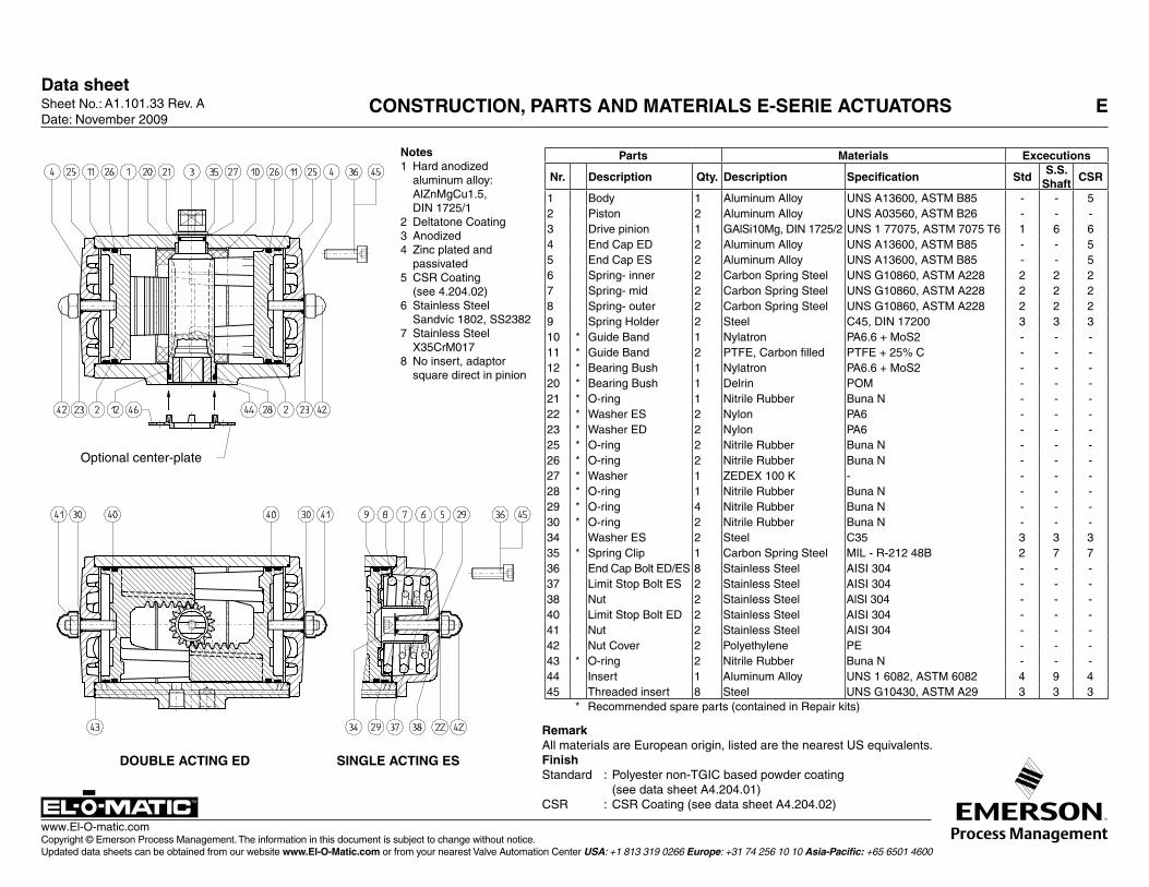
A1.101.33 Rev. A CONSTRUCTION, PARTS AND MATERIALS E-SERIE ACTUATORS E
Parts Materials Excecutions
Nr. Description Qty. Description Specification StdS.S.
ShaftCSR
1 Body 1 Aluminum Alloy UNS A13600, ASTM B85 - - 52 Piston 2 Aluminum Alloy UNS A03560, ASTM B26 - - -3 Drive pinion 1 GAlSi10Mg, DIN 1725/2 UNS 1 77075, ASTM 7075 T6 1 6 64 End Cap ED 2 Aluminum Alloy UNS A13600, ASTM B85 - - 55 End Cap ES 2 Aluminum Alloy UNS A13600, ASTM B85 - - 56 Spring- inner 2 Carbon Spring Steel UNS G10860, ASTM A228 2 2 27 Spring- mid 2 Carbon Spring Steel UNS G10860, ASTM A228 2 2 28 Spring- outer 2 Carbon Spring Steel UNS G10860, ASTM A228 2 2 29 Spring Holder 2 Steel C45, DIN 17200 3 3 310 * Guide Band 1 Nylatron PA6.6 + MoS2 - - -11 * Guide Band 2 PTFE, Carbon filled PTFE + 25% C - - -12 * Bearing Bush 1 Nylatron PA6.6 + MoS2 - - -20 * Bearing Bush 1 Delrin POM - - -21 * O-ring 1 Nitrile Rubber Buna N - - -22 * Washer ES 2 Nylon PA6 - - -23 * Washer ED 2 Nylon PA6 - - -25 * O-ring 2 Nitrile Rubber Buna N - - -26 * O-ring 2 Nitrile Rubber Buna N - - -27 * Washer 1 ZEDEX 100 K - - - -28 * O-ring 1 Nitrile Rubber Buna N - - -29 * O-ring 4 Nitrile Rubber Buna N - - -30 * O-ring 2 Nitrile Rubber Buna N - - -34 Washer ES 2 Steel C35 3 3 335 * Spring Clip 1 Carbon Spring Steel MIL - R-212 48B 2 7 736 End Cap Bolt ED/ES 8 Stainless Steel AISI 304 - - -37 Limit Stop Bolt ES 2 Stainless Steel AISI 304 - - -38 Nut 2 Stainless Steel AlSl 304 - - -40 Limit Stop Bolt ED 2 Stainless Steel AISI 304 - - -41 Nut 2 Stainless Steel AISI 304 - - -42 Nut Cover 2 Polyethylene PE - - -43 * O-ring 2 Nitrile Rubber Buna N - - -44 Insert 1 Aluminum Alloy UNS 1 6082, ASTM 6082 4 9 445 Threaded insert 8 Steel UNS G10430, ASTM A29 3 3 3
* Recommended spare parts (contained in Repair kits)
Notes1 Hard anodized
aluminum alloy: AlZnMgCu1.5, DIN 1725/1
2 Deltatone Coating3 Anodized4 Zinc plated and
passivated5 CSR Coating
(see 4.204.02)6 Stainless Steel
Sandvic 1802, SS23827 Stainless Steel
X35CrM0178 No insert, adaptor
square direct in pinion
Optional center-plate
DOUBLE ACTING ED SINGLE ACTING ES
RemarkAll materials are European origin, listed are the nearest US equivalents.FinishStandard : Polyester non-TGIC based powder coating (see data sheet A4.204.01)CSR : CSR Coating (see data sheet A4.204.02)
Data sheetSheet No.: Date: November 2009
Copyright © Emerson Process Management. The information in this document is subject to change without notice. Updated data sheets can be obtained from our website www.El-O-Matic.com or from your nearest Valve Automation Center USA: +1 813 319 0266 Europe: +31 74 256 10 10 Asia-Pacific: +65 6501 4600
www.El-O-matic.com
TM
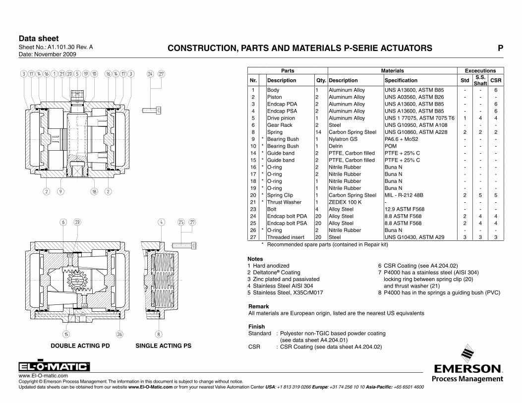
Notes1 Hard anodized 2 Deltatone® Coating3 Zinc plated and passivated4 Stainless Steel AISI 3045 Stainless Steel, X35CrM017
6 CSR Coating (see A4.204.02)7 P4000 has a stainless steel (AISI 304)
locking ring between spring clip (20) and thrust washer (21)
8 P4000 has in the springs a guiding bush (PVC)
RemarkAll materials are European origin, listed are the nearest US equivalents
FinishStandard : Polyester non-TGIC based powder coating (see data sheet A4.204.01)CSR : CSR Coating (see data sheet A4.204.02)
Parts Materials Excecutions
Nr. Description Qty. Description Specification StdS.S.
ShaftCSR
1 Body 1 Aluminum Alloy UNS A13600, ASTM B85 - - 62 Piston 2 Aluminum Alloy UNS A03560, ASTM B26 - - -3 Endcap PDA 2 Aluminum Alloy UNS A13600, ASTM B85 - - 64 Endcap PSA 2 Aluminum Alloy UNS A13600, ASTM B85 - - 65 Drive pinion 1 Aluminum Alloy UNS 1 77075, ASTM 7075 T6 1 4 46 Gear Rack 2 Steel UNS G10950, ASTM A108 - - -8 Spring 14 Carbon Spring Steel UNS G10860, ASTM A228 2 2 29 * Bearing Bush 1 Nylatron GS PA6.6 + MoS2 - - -
10 * Bearing Bush 1 Delrin POM - - -14 * Guide band 2 PTFE, Carbon filled PTFE + 25% C - - -15 * Guide band 2 PTFE, Carbon filled PTFE + 25% C - - -16 * O-ring 2 Nitrile Rubber Buna N - - -17 * O-ring 2 Nitrile Rubber Buna N - - -18 * O-ring 1 Nitrile Rubber Buna N - - -19 * O-ring 1 Nitrile Rubber Buna N - - -20 * Spring Clip 1 Carbon Spring Steel MIL - R-212 48B 2 5 521 * Thrust Washer 1 ZEDEX 100 K - - - -23 Bolt 4 Alloy Steel 12.9 ASTM F568 - - -24 Endcap bolt PDA 20 Alloy Steel 8.8 ASTM F568 2 4 425 Endcap bolt PSA 20 Alloy Steel 8.8 ASTM F568 2 4 426 * O-ring 2 Nitrile Rubber Buna N - - -27 Threaded insert 20 Steel UNS G10430, ASTM A29 3 3 3
* Recommended spare parts (contained in Repair kit)
DOUBLE ACTING PD SINGLE ACTING PS
A1.101.30 Rev. A CONSTRUCTION, PARTS AND MATERIALS P-SERIE ACTUATORS P
Data sheetSheet No.: Date: November 2009
Copyright © Emerson Process Management. The information in this document is subject to change without notice. Updated data sheets can be obtained from our website www.El-O-Matic.com or from your nearest Valve Automation Center USA: +1 813 319 0266 Europe: +31 74 256 10 10 Asia-Pacific: +65 6501 4600
www.El-O-matic.com
TM
5
6
8
10
12
13
14
1 2 34 7 911
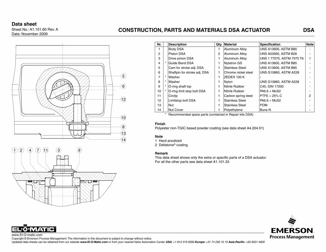
A1.101.60 Rev. A CONSTRUCTION, PARTS AND MATERIALS DSA ACTUATOR
Nr. Description Qty. Material Specification Note1 Body DSA 1 Aluminum Alloy UNS A13600, ASTM B85 -2 Piston DSA 2 Aluminum Alloy UNS A03560, ASTM B26 -3 Drive pinion DSA 1 Aluminum Alloy UNS 1 77075, ASTM 7075 T6 14 * Guide Band DSA 1 Nylatron GS UNS A13600, ASTM B85 -5 Cam for stroke adj. DSA 1 Stainless Steel UNS A13600, ASTM B85 -6 Shaftpin for stroke adj. DSA 1 Chrome nickel steel UNS G10860, ASTM A228 -7 * Washer 1 ZEDEX 100 K - -8 * Washer 1 Nylon UNS G10860, ASTM A228 -9 * O-ring shaft top 1 Nitrile Rubber C45, DIN 17200 -
10 * O-ring limit stop bolt DSA 1 Nitrile Rubber PA6.6 + MoS2 -11 Circlip 1 Carbon spring steel PTFE + 25% C 212 Limitstop bolt DSA 1 Stainless Steel PA6.6 + MoS2 -13 Nut 1 Stainless Steel POM -14 Nut Cover 1 Polyethylene Buna N -
* Recommended spare parts (contained in Repair kits DSA)
Finish Polyester non-TGIC based powder coating (see data sheet A4.204.01)
Note 1 Hard anodized2 Deltatone® coating
RemarkThis data sheet shows only the extra or specific parts of a DSA actuator. For all the other parts see data sheet A1.101.33
DSA
Data sheet
Copyright © Emerson Process Management. The information in this document is subject to change without notice. Updated data sheets can be obtained from our website www.El-O-Matic.com or from your nearest Valve Automation Center USA: +1 813 319 0266 Europe: +31 74 256 10 10 Asia-Pacific: +65 6501 4600
www.El-O-matic.com
Sheet No.: Date: June 2010
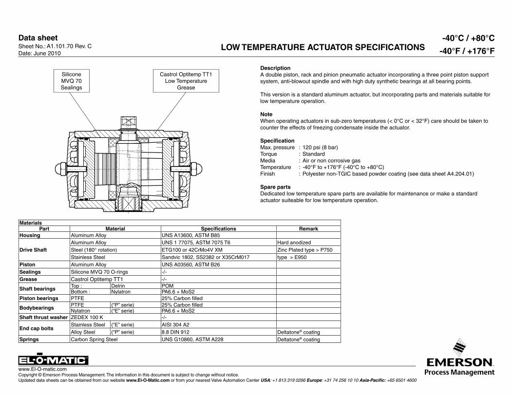
A1.101.70 Rev. C LOW TEMPERATURE ACTUATOR SPECIFICATIONS-40°C / +80°C
-40°F / +176°F
Silicone MVQ 70 Sealings
Castrol Optitemp TT1Low Temperature
Grease
MaterialsPart Material Specifications Remark
Housing Aluminum Alloy UNS A13600, ASTM B85
Drive ShaftAluminum Alloy UNS 1 77075, ASTM 7075 T6 Hard anodizedSteel (180° rotation) ETG100 or 42CrMo4V XM Zinc Plated type > P750Stainless Steel Sandvic 1802, SS2382 or X35CrM017 type > E950
Piston Aluminum Alloy UNS A03560, ASTM B26Sealings Silicone MVQ 70 O-rings -/-Grease Castrol Optitemp TT1 -/-
Shaft bearings Top : Delrin POMBottom : Nylatron PA6.6 + MoS2
Piston bearings PTFE 25% Carbon filled
Bodybearings PTFE (“P” serie) 25% Carbon filled Nylatron (“E” serie) PA6.6 + MoS2
Shaft thrust washer ZEDEX 100 K -/-
End cap boltsStainless Steel (“E” serie) AISI 304 A2Alloy Steel (“P” serie) 8.8 DIN 912 Deltatone® coating
Springs Carbon Spring Steel UNS G10860, ASTM A228 Deltatone® coating
DescriptionA double piston, rack and pinion pneumatic actuator incorporating a three point piston support system, anti-blowout spindle and with high duty synthetic bearings at all bearing points.
This version is a standard aluminum actuator, but incorporating parts and materials suitable for low temperature operation.
NoteWhen operating actuators in sub-zero temperatures (< 0°C or < 32°F) care should be taken to counter the effects of freezing condensate inside the actuator.
SpecificationMax. pressure : 120 psi (8 bar)Torque : StandardMedia : Air or non corrosive gasTemperature : -40°F to +176°F (-40°C to +80°C) Finish : Polyester non-TGIC based powder coating (see data sheet A4.204.01)
Spare partsDedicated low temperature spare parts are available for maintenance or make a standard actuator suiteable for low temperature operation.
Data sheet
Copyright © Emerson Process Management. The information in this document is subject to change without notice. Updated data sheets can be obtained from our website www.El-O-Matic.com or from your nearest Valve Automation Center USA: +1 813 319 0266 Europe: +31 74 256 10 10 Asia-Pacific: +65 6501 4600
www.El-O-matic.com
Sheet No.: Date: January 2010
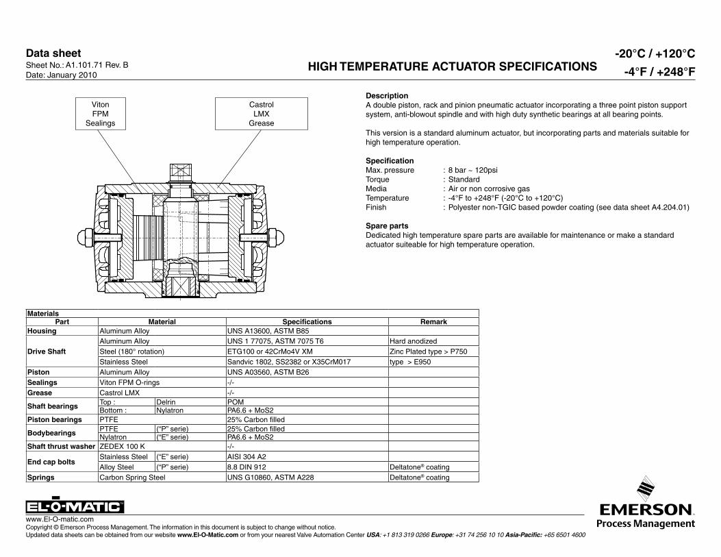
A1.101.71 Rev. B HIGH TEMPERATURE ACTUATOR SPECIFICATIONS-20°C / +120°C
-4°F / +248°F
VitonFPM
Sealings
CastrolLMX
Grease
DescriptionA double piston, rack and pinion pneumatic actuator incorporating a three point piston support system, anti-blowout spindle and with high duty synthetic bearings at all bearing points.
This version is a standard aluminum actuator, but incorporating parts and materials suitable for high temperature operation.
SpecificationMax. pressure : 8 bar ~ 120psiTorque : StandardMedia : Air or non corrosive gasTemperature : -4°F to +248°F (-20°C to +120°C)Finish : Polyester non-TGIC based powder coating (see data sheet A4.204.01)
Spare partsDedicated high temperature spare parts are available for maintenance or make a standard actuator suiteable for high temperature operation.
MaterialsPart Material Specifications Remark
Housing Aluminum Alloy UNS A13600, ASTM B85
Drive ShaftAluminum Alloy UNS 1 77075, ASTM 7075 T6 Hard anodizedSteel (180° rotation) ETG100 or 42CrMo4V XM Zinc Plated type > P750Stainless Steel Sandvic 1802, SS2382 or X35CrM017 type > E950
Piston Aluminum Alloy UNS A03560, ASTM B26Sealings Viton FPM O-rings -/-Grease Castrol LMX -/-
Shaft bearings Top : Delrin POMBottom : Nylatron PA6.6 + MoS2
Piston bearings PTFE 25% Carbon filled
Bodybearings PTFE (“P” serie) 25% Carbon filled Nylatron (“E” serie) PA6.6 + MoS2
Shaft thrust washer ZEDEX 100 K -/-
End cap boltsStainless Steel (“E” serie) AISI 304 A2Alloy Steel (“P” serie) 8.8 DIN 912 Deltatone® coating
Springs Carbon Spring Steel UNS G10860, ASTM A228 Deltatone® coating
Data sheetSheet No.: Date: November 2009
Copyright © Emerson Process Management. The information in this document is subject to change without notice. Updated data sheets can be obtained from our website www.El-O-Matic.com or from your nearest Valve Automation Center USA: +1 813 319 0266 Europe: +31 74 256 10 10 Asia-Pacific: +65 6501 4600
www.El-O-matic.com
TM
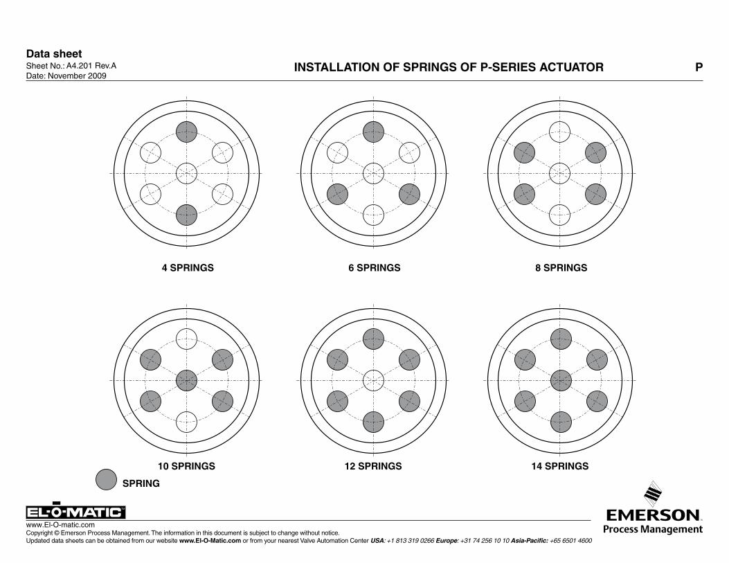
A4.201 Rev.A INSTALLATION OF SPRINGS OF P-SERIES ACTUATOR P
4 SPRINGS 6 SPRINGS 8 SPRINGS
10 SPRINGS 12 SPRINGS 14 SPRINGS
SPRING
Data sheetSheet No.: Date: November 2009
Copyright © Emerson Process Management. The information in this document is subject to change without notice. Updated data sheets can be obtained from our website www.El-O-Matic.com or from your nearest Valve Automation Center USA: +1 813 319 0266 Europe: +31 74 256 10 10 Asia-Pacific: +65 6501 4600
www.El-O-matic.com
TM
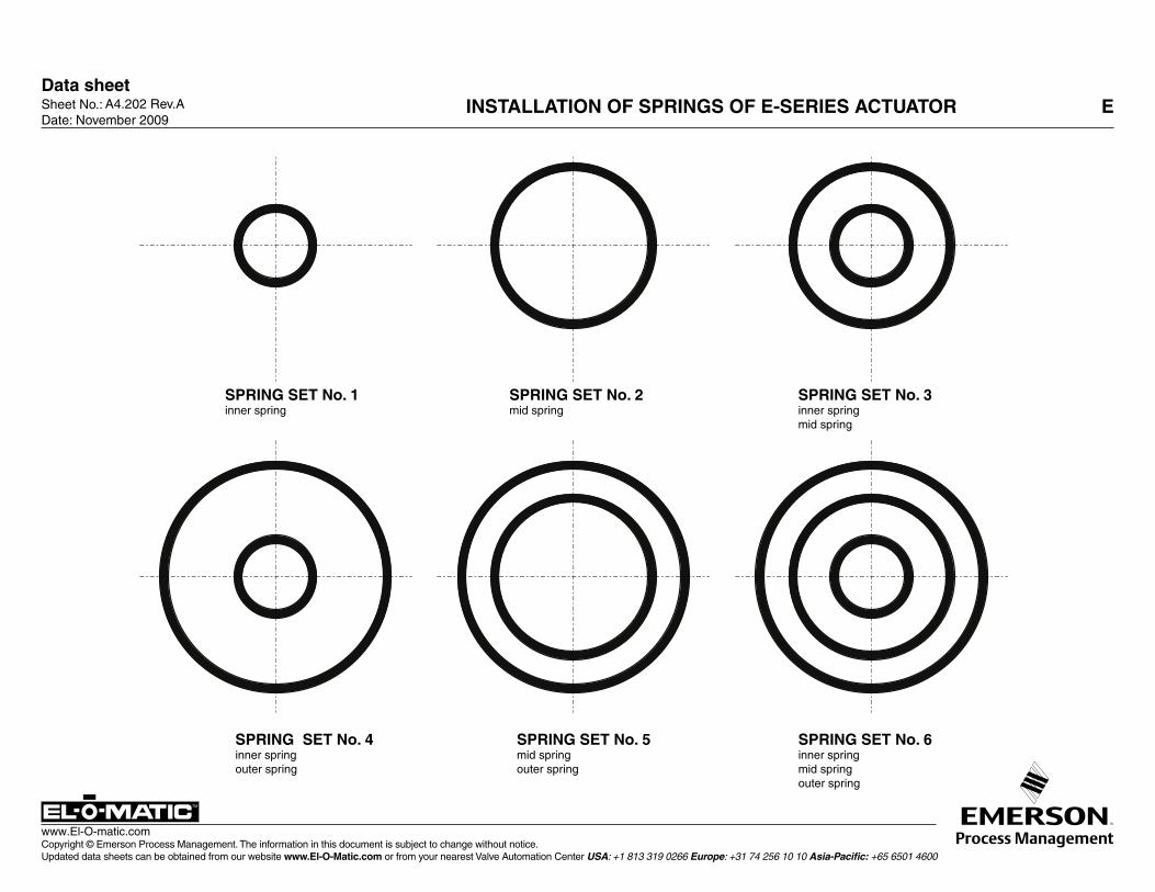
SPRING SET No. 4inner springouter spring
SPRING SET No. 1inner spring
SPRING SET No. 2mid spring
SPRING SET No. 5mid springouter spring
SPRING SET No. 6inner springmid springouter spring
SPRING SET No. 3inner springmid spring
A4.202 Rev.A INSTALLATION OF SPRINGS OF E-SERIES ACTUATOR E
Data sheetSheet No.: Date: November 2009
Copyright © Emerson Process Management. The information in this document is subject to change without notice. Updated data sheets can be obtained from our website www.El-O-Matic.com or from your nearest Valve Automation Center USA: +1 813 319 0266 Europe: +31 74 256 10 10 Asia-Pacific: +65 6501 4600
www.El-O-matic.com
TM
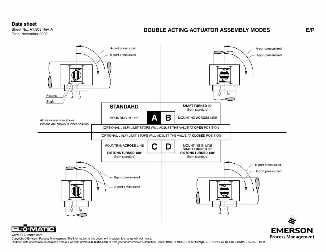
A1.503 Rev. A DOUBLE ACTING ACTUATOR ASSEMBLY MODES E/P
A B
A B
A B
A B
A-port pressurized
B-port pressurized
Pistons
Shaft
A-port pressurized
B-port pressurized
B-port pressurized
A-port pressurized
B-port pressurized
A-port pressurized
B
SHAFT TURNED 90°(from standard)
STANDARD
DC
MOUNTING ACROSS LINE
MOUNTING IN LINE
MOUNTING IN LINE
MOUNTING ACROSS LINESHAFT TURNED 90°
PISTONS TURNED 180°(from standard)
PISTONS TURNED 180° (from standard)
(OPTIONAL L1/LF) LIMIT STOPS WILL ADJUST THE VALVE AT OPEN POSITION
(OPTIONAL L1/LF) LIMIT STOPS WILL ADJUST THE VALVE AT CLOSED POSITION
All views are from abovePistons are shown in inner position
A
Data sheetSheet No.: Date: November 2009
Copyright © Emerson Process Management. The information in this document is subject to change without notice. Updated data sheets can be obtained from our website www.El-O-Matic.com or from your nearest Valve Automation Center USA: +1 813 319 0266 Europe: +31 74 256 10 10 Asia-Pacific: +65 6501 4600
www.El-O-matic.com
TM
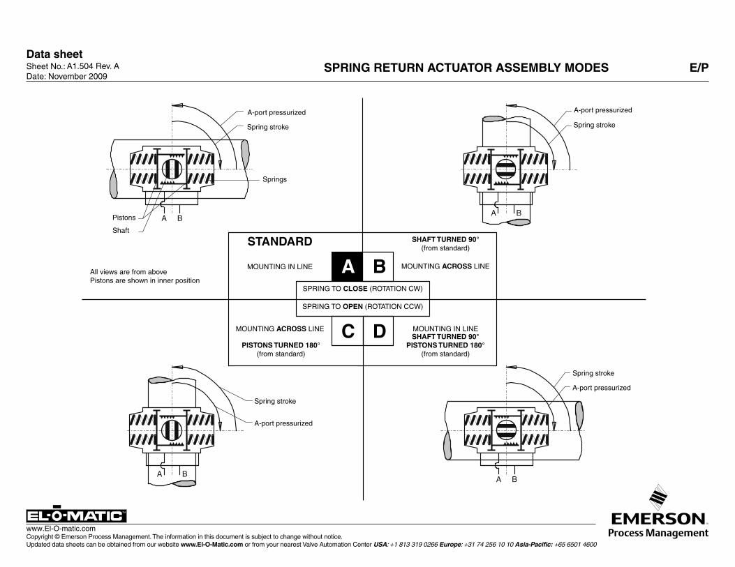
A1.504 Rev. A SPRING RETURN ACTUATOR ASSEMBLY MODES E/P
A B
A B
A B
A B
SPRING TO OPEN (ROTATION CCW)
B
SHAFT TURNED 90°(from standard)
STANDARD
DC
MOUNTING ACROSS LINE
MOUNTING IN LINE
MOUNTING IN LINE
MOUNTING ACROSS LINESHAFT TURNED 90°
PISTONS TURNED 180°(from standard)
PISTONS TURNED 180° (from standard)
SPRING TO CLOSE (ROTATION CW)
A-port pressurized
Spring stroke
Springs
Pistons
Shaft
A-port pressurized
Spring stroke
A-port pressurized
Spring stroke
Spring stroke
A-port pressurized
AAll views are from abovePistons are shown in inner position
Data sheet
Copyright © Emerson Process Management. The information in this document is subject to change without notice. Updated data sheets can be obtained from our website www.El-O-Matic.com or from your nearest Valve Automation Center USA: +1 813 319 0266 Europe: +31 74 256 10 10 Asia-Pacific: +65 6501 4600
www.El-O-matic.com
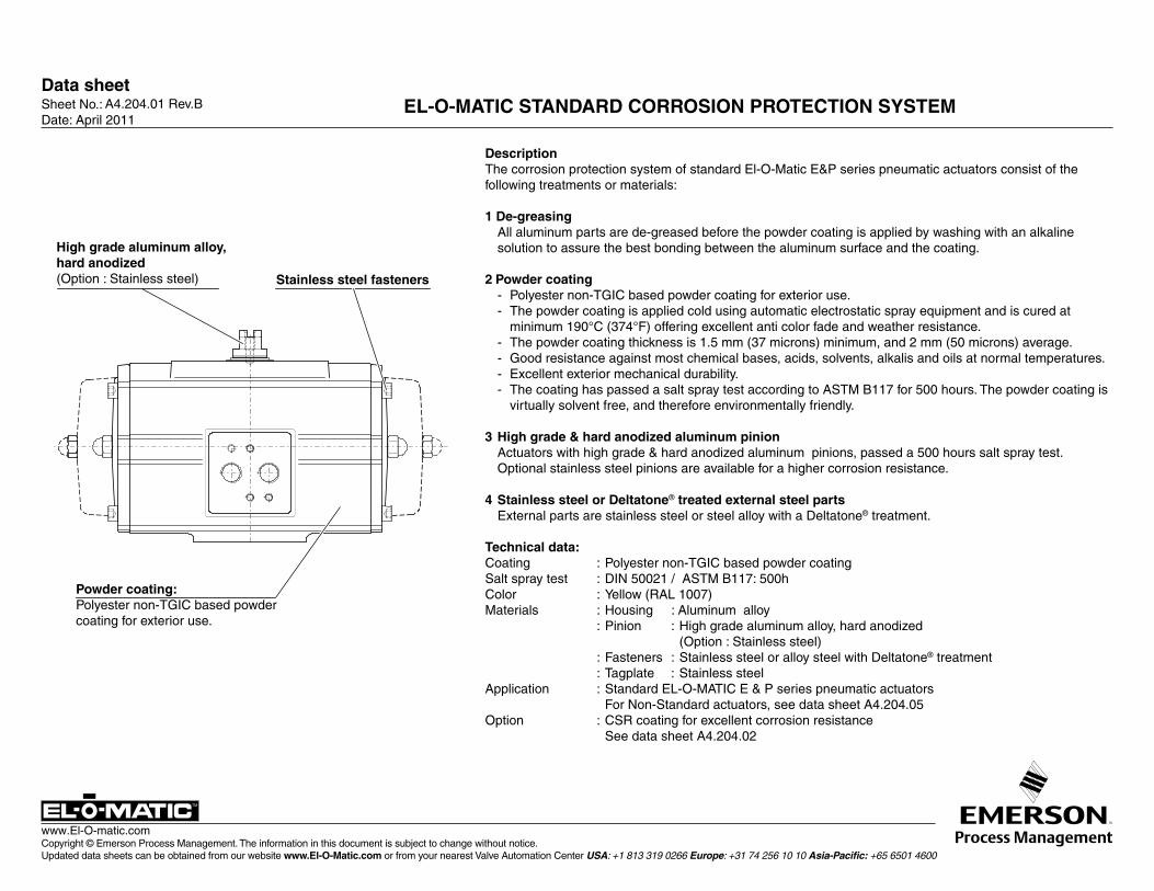
DescriptionThe corrosion protection system of standard El-O-Matic E&P series pneumatic actuators consist of the following treatments or materials:
1 De-greasing All aluminum parts are de-greased before the powder coating is applied by washing with an alkaline
solution to assure the best bonding between the aluminum surface and the coating.
2 Powder coating - Polyester non-TGIC based powder coating for exterior use. - The powder coating is applied cold using automatic electrostatic spray equipment and is cured at
minimum 190°C (374°F) offering excellent anti color fade and weather resistance. - The powder coating thickness is 1.5 mm (37 microns) minimum, and 2 mm (50 microns) average. - Good resistance against most chemical bases, acids, solvents, alkalis and oils at normal temperatures. - Excellent exterior mechanical durability. - The coating has passed a salt spray test according to ASTM B117 for 500 hours. The powder coating is
virtually solvent free, and therefore environmentally friendly.
3 High grade & hard anodized aluminum pinion Actuators with high grade & hard anodized aluminum pinions, passed a 500 hours salt spray test.
Optional stainless steel pinions are available for a higher corrosion resistance.
4 Stainless steel or Deltatone® treated external steel parts External parts are stainless steel or steel alloy with a Deltatone® treatment.
Technical data:Coating : Polyester non-TGIC based powder coating Salt spray test : DIN 50021 / ASTM B117: 500hColor : Yellow (RAL 1007) Materials : Housing : Aluminum alloy : Pinion : High grade aluminum alloy, hard anodized
(Option : Stainless steel) : Fasteners : Stainless steel or alloy steel with Deltatone® treatment : Tagplate : Stainless steelApplication : Standard EL-O-MATIC E & P series pneumatic actuators
For Non-Standard actuators, see data sheet A4.204.05Option : CSR coating for excellent corrosion resistance
See data sheet A4.204.02
High grade aluminum alloy, hard anodized(Option : Stainless steel) Stainless steel fasteners
Powder coating:Polyester non-TGIC based powder coating for exterior use.
A4.204.01 Rev.B EL-O-MATIC STANDARD CORROSION PROTECTION SYSTEM Sheet No.: Date: April 2011
Data sheet
Copyright © Emerson Process Management. The information in this document is subject to change without notice. Updated data sheets can be obtained from our website www.El-O-Matic.com or from your nearest Valve Automation Center USA: +1 813 319 0266 Europe: +31 74 256 10 10 Asia-Pacific: +65 6501 4600
www.El-O-matic.com
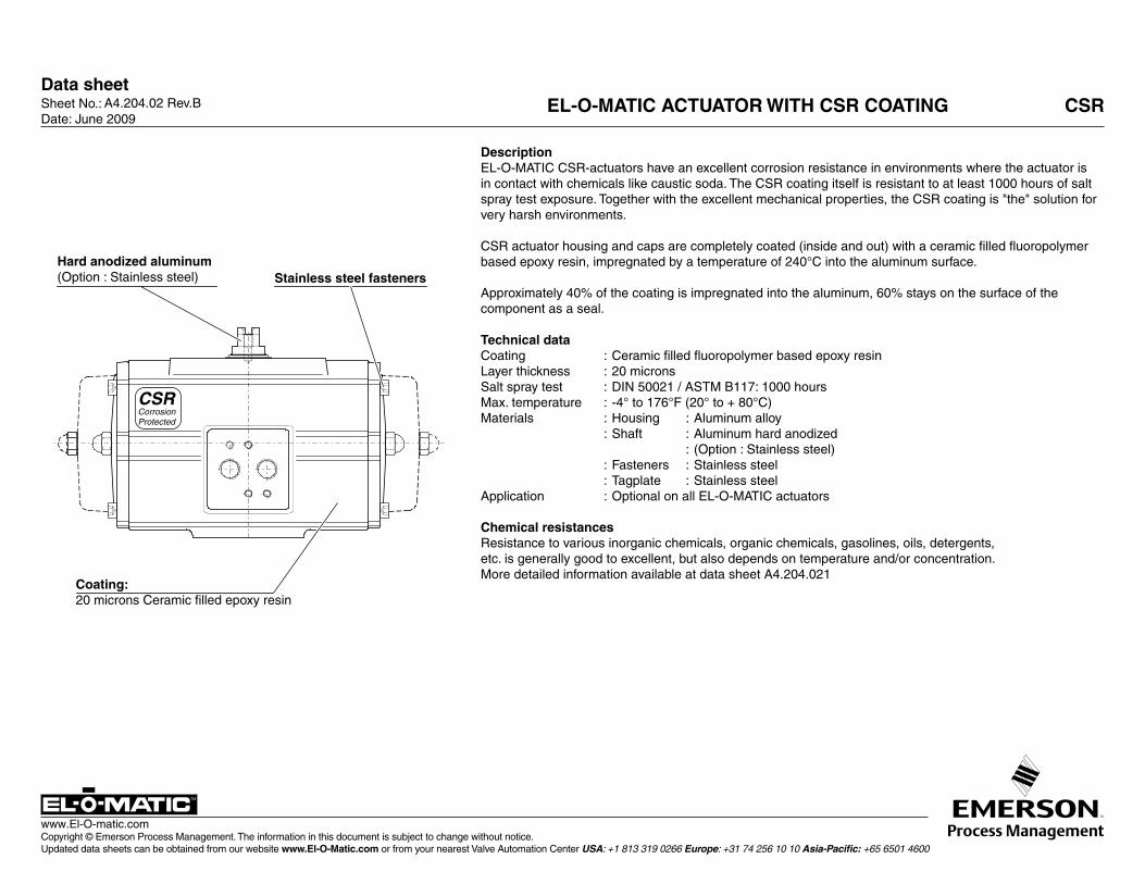
DescriptionEL-O-MATIC CSR-actuators have an excellent corrosion resistance in environments where the actuator is in contact with chemicals like caustic soda. The CSR coating itself is resistant to at least 1000 hours of salt spray test exposure. Together with the excellent mechanical properties, the CSR coating is "the" solution for very harsh environments.
CSR actuator housing and caps are completely coated (inside and out) with a ceramic filled fluoropolymer based epoxy resin, impregnated by a temperature of 240°C into the aluminum surface. Approximately 40% of the coating is impregnated into the aluminum, 60% stays on the surface of the component as a seal.
Technical dataCoating : Ceramic filled fluoropolymer based epoxy resinLayer thickness : 20 micronsSalt spray test : DIN 50021 / ASTM B117: 1000 hoursMax. temperature : -4° to 176°F (20° to + 80°C)Materials : Housing : Aluminum alloy : Shaft : Aluminum hard anodized : (Option : Stainless steel) : Fasteners : Stainless steel : Tagplate : Stainless steelApplication : Optional on all EL-O-MATIC actuators
Chemical resistancesResistance to various inorganic chemicals, organic chemicals, gasolines, oils, detergents, etc. is generally good to excellent, but also depends on temperature and/or concentration.More detailed information available at data sheet A4.204.021
A4.204.02 Rev.B EL-O-MATIC ACTUATOR WITH CSR COATING CSR
CSRCorrosionProtected
Hard anodized aluminum (Option : Stainless steel) Stainless steel fasteners
Coating:20 microns Ceramic filled epoxy resin
Sheet No.: Date: June 2009
Data sheetSheet No.: Date: November 2009
Copyright © Emerson Process Management. The information in this document is subject to change without notice. Updated data sheets can be obtained from our website www.El-O-Matic.com or from your nearest Valve Automation Center USA: +1 813 319 0266 Europe: +31 74 256 10 10 Asia-Pacific: +65 6501 4600
www.El-O-matic.com
TM
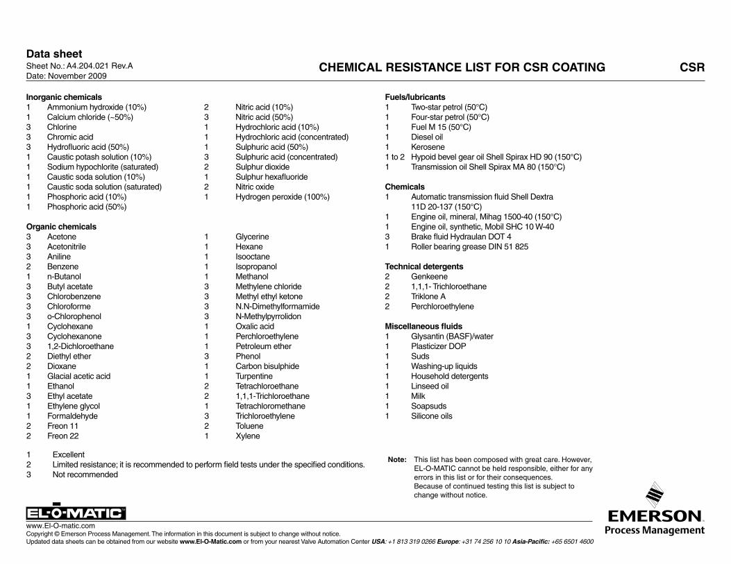
A4.204.021 Rev.A CHEMICAL RESISTANCE LIST FOR CSR COATING CSR
Note: This list has been composed with great care. However, EL -O - MATIC cannot be held responsible, either for any errors in this list or for their consequences.
Because of continued testing this list is subject to change without notice.
Inorganic chemicals1 Ammonium hydroxide (10%) 2 Nitric acid (10%)1 Calcium chloride (~50%) 3 Nitric acid (50%)3 Chlorine 1 Hydrochloric acid (10%)3 Chromic acid 1 Hydrochloric acid (concentrated)3 Hydrofluoric acid (50%) 1 Sulphuric acid (50%)1 Caustic potash solution (10%) 3 Sulphuric acid (concentrated)1 Sodium hypochlorite (saturated) 2 Sulphur dioxide1 Caustic soda solution (10%) 1 Sulphur hexafluoride1 Caustic soda solution (saturated) 2 Nitric oxide1 Phosphoric acid (10%) 1 Hydrogen peroxide (100%)1 Phosphoric acid (50%)
Organic chemicals 3 Acetone 1 Glycerine3 Acetonitrile 1 Hexane3 Aniline 1 Isooctane2 Benzene 1 Isopropanol1 n-Butanol 1 Methanol3 Butyl acetate 3 Methylene chloride3 Chlorobenzene 3 Methyl ethyl ketone3 Chloroforme 3 N.N-Dimethylformamide3 o-Chlorophenol 3 N-Methylpyrrolidon1 Cyclohexane 1 Oxalic acid3 Cyclohexanone 1 Perchloroethylene3 1,2-Dichloroethane 1 Petroleum ether2 Diethyl ether 3 Phenol2 Dioxane 1 Carbon bisulphide1 Glacial acetic acid 1 Turpentine1 Ethanol 2 Tetrachloroethane3 Ethyl acetate 2 1,1,1-Trichloroethane1 Ethylene glycol 1 Tetrachloromethane1 Formaldehyde 3 Trichloroethylene2 Freon 11 2 Toluene2 Freon 22 1 Xylene
Fuels/lubricants1 Two-star petrol (50°C)1 Four-star petrol (50°C)1 Fuel M 15 (50°C)1 Diesel oil1 Kerosene1 to 2 Hypoid bevel gear oil Shell Spirax HD 90 (150°C)1 Transmission oil Shell Spirax MA 80 (150°C)
Chemicals1 Automatic transmission fluid Shell Dextra 11D 20-137 (150°C)1 Engine oil, mineral, Mihag 1500-40 (150°C)1 Engine oil, synthetic, Mobil SHC 10 W-403 Brake fluid Hydraulan DOT 41 Roller bearing grease DIN 51 825
Technical detergents2 Genkeene2 1,1,1- Trichloroethane2 Triklone A2 Perchloroethylene
Miscellaneous fluids1 Glysantin (BASF)/water1 Plasticizer DOP1 Suds1 Washing-up liquids1 Household detergents1 Linseed oil1 Milk1 Soapsuds1 Silicone oils
1 Excellent2 Limited resistance; it is recommended to perform field tests under the specified conditions.3 Not recommended
Data sheetSheet No.: Date: November 2009
Copyright © Emerson Process Management. The information in this document is subject to change without notice. Updated data sheets can be obtained from our website www.El-O-Matic.com or from your nearest Valve Automation Center USA: +1 813 319 0266 Europe: +31 74 256 10 10 Asia-Pacific: +65 6501 4600
www.El-O-matic.com
TM
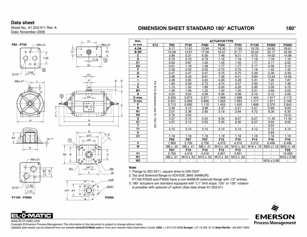
A1.203.011 Rev. A DIMENSION SHEET STANDARD 180° ACTUATOR 180°
Dim.in mm.
ACTUATOR TYPEE12 P60 P150 P280 P500 P750 P1100 P2500 P4000
A DA
For E
12 dimensions see A
1.103.102
9.17 11.61 13.94 16.30 17.60 19.76 24.92 29.61B SR 10.08 13.07 17.09 19.57 21.77 25.24 32.17 42.95
C 3.98 5.31 6.30 7.48 9.21 9.72 14.02 14.96D 0.79 0.79 0.79 1.18 1.18 1.18 1.18 1.18E1 0.63 0.87 1.02 1.42 1.42 1.77 2.17 2.52E2 0.91 1.18 1.38 1.77 1.77 2.17 2.56 3.15F 0.39 0.55 0.55 0.75 0.75 1.18 1.42 1.42G 0.47 0.47 0.47 0.75 0.75 0.39 0.39 0.39H 3.98 5.43 6.61 7.56 9.41 9.84 13.54 14.65I 2.28 2.95 3.50 4.29 5.28 5.31 7.20 7.87J 1.69 2.09 2.72 3.74 4.57 4.92 7.01 7.48K 1.10 1.50 1.89 2.20 2.20 2.95 3.35 4.72
M1 1.06 1.06 1.22 1.50 1.50 2.01 2.60 3.03N 0.04 0.04 0.06 0.06 0.08 0.10 0.12 0.06
O max. 0.556 0.674 0.871 1.068 1.068 1.424 1.817 2.173O min. 0.551 0.669 0.866 1.063 1.063 1.417 1.811 2.165
P 0.713 0.992 1.110 1.425 1.425 1.898 2.370 2.843R 2.36 3.15 3.98 4.37 5.51 5.51 6.69 6.69R1 2.01 2.36 2.80 3.19 3.94 4.72 6.30 6.30R2 2.76 3.94 - - - - - 10.31S 4.37 5.12 5.55 6.34 8.27 8.27 11.42 11.42S1 4.37 5.12 5.55 5.55 6.30 8.27 9.65 9.65T - - - - - - 9.24 -T1 3.15 3.15 3.15 5.12 5.12 5.12 5.12 5.12U - - - - - - 3.83 -U1 1.18 1.18 1.18 1.18 1.18 1.18 1.18 1.18
F05 F07 F07 F10 F10 F14 F16 F16V 1.969 2.756 2.756 4.016 4.016 5.512 6.496 6.496W M6 x .35 M8 x .51 M8 x .51 M10 x .63 M10 x .63 M16 x .79 M20 x1.18 M20 x1.18
F07 F10 F10 F12 F12 - - F25V1 2.756 4.016 4.016 4.921 4.921 - - 10.000W1 M8 x .51 M10 x .63 M10 x .63 M12 x .63 M12 x .63 - - M16 x 0.98W2 - - - - - - M16 x 0.98 -
Note1. Flange to ISO 5211, square drive to DIN 33372. Top and Solenoid flange to VDI/VDE 3845 (NAMUR).
P1100 P2500 and P4000 have a non-NAMUR solenoid flange with 1/2" entries.3. 180° actuators are standard equipped with "L1" limit stops. 120° or 135° rotation
is possible with optional LF-option (See data sheet A1.503.01)
P60 - P750
0.94
1.26
M5x.31
G1/4"
IM6x.47
4
H
K
M1 N ±0.02
øV1
4xW
øV8xW1
W1øP+0.02
0
W
W2
T
O
RR2
S
øV
øV1
U
B
A
0.16
U1
T1
R1
S1
M5x.31
E1
F
E2
J
G D
C
2
2
3
P1100 - P4000 P4000
M5x.31
1.00
1.37
1.00G1/2"
1.37
1
Data sheet
Copyright © Emerson Process Management. The information in this document is subject to change without notice. Updated data sheets can be obtained from our website www.El-O-Matic.com or from your nearest Valve Automation Center USA: +1 813 319 0266 Europe: +31 74 256 10 10 Asia-Pacific: +65 6501 4600
www.El-O-matic.com
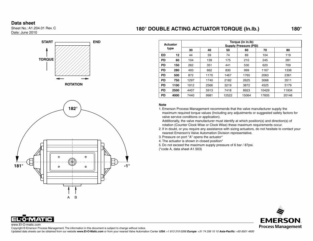
A1.204.01 Rev. C 180° DOUBLE ACTING ACTUATOR TORQUE (In.lb.) 180°
Actuatortype
Torque (in in.lb)Supply Pressure (PSI)
30 40 50 60 70 80
ED 12 44 59 74 89 104 119
PD 60 104 139 175 210 245 281
PD 150 262 351 441 530 620 709
PD 280 493 662 830 999 1167 1336
PD 500 872 1170 1467 1765 2063 2361
PD 750 1297 1740 2182 2625 3068 3511
PD 1100 1912 2566 3219 3872 4525 5179
PD 2500 4407 5913 7418 8923 10429 11934
PD 4000 7440 9981 12522 15064 17605 20146
Note1. Emerson Process Management recommends that the valve manufacturer supply the
maximum required torque values (Including any adjustments or suggested safety factors for valve service conditions or application).
Additionally, the valve manufacturer must identify at which position(s) and direction(s) of rotation (Counter Clock Wise or Clock Wise) these maximum requirements occur.
2. If in doubt, or you require any assistance with sizing actuators, do not hesitate to contact your nearest Emerson's Valve Automation Division representative.
3. Pressure on port "A" opens the actuator*4. The actuator is shown in closed position* 5. Do not exceed the maximum supply pressure of 6 bar / 87psi.(*code A, data sheet A1.503)
A B
182°
181° -1°
TORQUE
START END
ROTATION
Sheet No.: Date: June 2010
Data sheet
Copyright © Emerson Process Management. The information in this document is subject to change without notice. Updated data sheets can be obtained from our website www.El-O-Matic.com or from your nearest Valve Automation Center USA: +1 813 319 0266 Europe: +31 74 256 10 10 Asia-Pacific: +65 6501 4600
www.El-O-matic.com
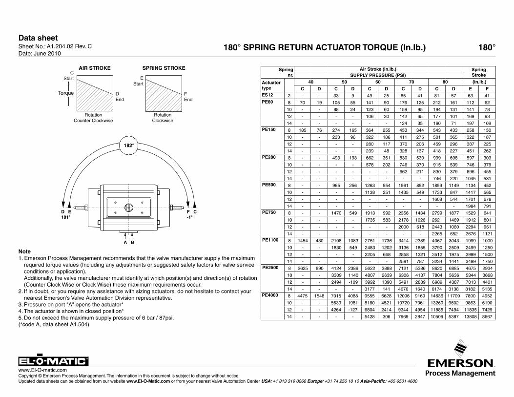
A1.204.02 Rev. C 180° SPRING RETURN ACTUATOR TORQUE (In.lb.) 180°
Note1. Emerson Process Management recommends that the valve manufacturer supply the maximum
required torque values (Including any adjustments or suggested safety factors for valve service conditions or application).
Additionally, the valve manufacturer must identify at which position(s) and direction(s) of rotation (Counter Clock Wise or Clock Wise) these maximum requirements occur.
2. If in doubt, or you require any assistance with sizing actuators, do not hesitate to contact your nearest Emerson's Valve Automation Division representative.
3. Pressure on port "A" opens the actuator*4. The actuator is shown in closed position* 5. Do not exceed the maximum supply pressure of 6 bar / 87psi.(*code A, data sheet A1.504)
Spring nr.
Air Stroke (in.lb.) SpringStrokeSUPPLY PRESSURE (PSI)
Actuatortype
40 50 60 70 80 (in.lb.)
C D C D C D C D C D E FES12 2 - - 33 9 49 25 65 41 81 57 63 41PE60 8 70 19 105 55 141 90 176 125 212 161 112 62
10 - - 88 24 123 60 159 95 194 131 141 78
12 - - - - 106 30 142 65 177 101 169 93
14 - - - - - - 124 35 160 71 197 109PE150 8 185 76 274 165 364 255 453 344 543 433 258 150
10 - - 233 96 322 186 411 275 501 365 322 187
12 - - - - 280 117 370 206 459 296 387 225
14 - - - - 239 48 328 137 418 227 451 262PE280 8 - - 493 193 662 361 830 530 999 698 597 303
10 - - - - 578 202 746 370 915 539 746 379
12 - - - - - - 662 211 830 379 896 455
14 - - - - - - - - 746 220 1045 531PE500 8 - - 965 256 1263 554 1561 852 1859 1149 1134 452
10 - - - - 1138 251 1435 549 1733 847 1417 565
12 - - - - - - - - 1608 544 1701 678
14 - - - - - - - - - - 1984 791PE750 8 - - 1470 549 1913 992 2356 1434 2799 1877 1529 641
10 - - - - 1735 583 2178 1026 2621 1469 1912 801
12 - - - - - - 2000 618 2443 1060 2294 961
14 - - - - - - - - 2265 652 2676 1121PE1100 8 1454 430 2108 1083 2761 1736 3414 2389 4067 3043 1999 1000
10 - - 1830 549 2483 1202 3136 1855 3790 2509 2499 1250
12 - - - - 2205 668 2858 1321 3512 1975 2999 1500
14 - - - - - - 2581 787 3234 1441 3499 1750PE2500 8 2625 890 4124 2389 5622 3888 7121 5386 8620 6885 4675 2934
10 - - 3309 1140 4807 2639 6306 4137 7804 5636 5844 3668
12 - - 2494 -109 3992 1390 5491 2889 6989 4387 7013 4401
14 - - - - 3177 141 4676 1640 6174 3138 8182 5135PE4000 8 4475 1548 7015 4088 9555 6628 12096 9169 14636 11709 7890 4952
10 - - 5639 1981 8180 4521 10720 7061 13260 9602 9863 6190
12 - - 4264 -127 6804 2414 9344 4954 11885 7494 11835 7429
14 - - - - 5428 306 7969 2847 10509 5387 13808 8667
D E181°
F C-1°
A B
182°
SPRING STROKEAIR STROKE
FEnd
RotationClockwise
DEnd
RotationCounter Clockwise
CStart
Torque
EStart
Sheet No.: Date: June 2010
© 2010 Emerson Process Management. All rights reserved.The Emerson logo is a trademark and service mark of Emerson Electric Co. “Brand mark listing” are marks of one of the Emerson Process Management family of companies. All other marks are property of their respective owners.The contents of this publication are presented for information purposes only, and while every effort has been made to ensure their accuracy, they are not to be construed as warranties or guarantees, express or implied, regarding the products or services described herein or their use or applicability. All sales are governed by our terms and conditions, which are available on request. We reserve the right to modify or improve the designs or specifications of our products at any time without notice.EL-O-MATIC® is a registered trademark of EL-O-MATIC B.V.
Contact Us: Emerson Process Management, Valve Automation facilities at your nearest location:
North & South AmericA
18703 GH Circle PO Box 508 Waller, TX 77484 USA T +1 281 727 5300 F +1 281 727 5353
2500 Park Avenue West Mansfield, OH 44906 USA T +1 419 529 4311 F +1 419 529 3688
9009 King Palm Drive Tampa, FL 33619 USA T +1 813 630 2255 F +1 813 630 9449
13840 Pike RoadMissouri City, Texas 77489USAT +1 281 499 1561F +1 281 499 8445
Av. Hollingsworth, 325, Iporanga Sorocaba, SP 18087-105 Brazil T +55 15 3238 3788 F +55 15 3228 3300
middle eASt & AfricA
P. O. Box 17033 Dubai United Arab Emirates T +971 4 811 8100 F +971 4 886 5465
P. O. Box 105958 Abu Dhabi United Arab Emirates T +971 2 697 2000 F +971 2 555 0364
P. O. Box 3911 Al Khobar 31952 Saudi Arabia T +966 3 814 7560 F +966 3 814 7570
P. O. Box 10305Jubail 31961Saudi ArabiaT +966 3 340 8650F +966 3 340 8790
P. O. Box 32281 Doha Qatar T +974 4 576777 F +974 4 315448
2 Monteer Road, Isando Kempton Park, 1600 South Africa T +27 11 974 3336 F +27 11 974 7005
europe
Asveldweg 11 7556 BR Hengelo (O) The Netherlands T +31 74 256 1010 F +31 74 291 0938
Siemensring 11247877 Willich Germany T +49 2154 499 660 F +49 2154 499 6613
25, Rue de VilleneuveSilic – BP 4043494583 RUNGIS Cedex France T +33 1 49 79 73 00 F +33 1 49 79 73 99
Via Montello 71/73 20038 Seregno (Milan) Italy T +39 0362 2285 207 F +39 0362 2436 55
6 Bracken Hill South West Industrial EstatePeterlee SR8 2LS United Kingdom T +44 191 518 0020 F +44 191 518 0032
ul. Konstruktorska str 11A02-673 WarsawPolandT +48 22 4589237F +48 22 45 89 231
C/ Francisco Gervás, 128108 Alcobendas – MadridSpainT +34 0913 586 000F +34 0913 589 145
Letnikovskaya Str. 10-2115114 MoscowRussia and FSUT +7 495 981 98 11F +7 495 981 98 10
ASiA pAcific
No. 9 Gul Road#01-02 Singapore 629361T +65 6501 4600 F +65 6268 0028
9/F Gateway Building No. 10 Ya Bao Road Chaoyang District Beijing 100020 P.R.China T +86 10 5821 1188 F +86 10 5821 1100
No.15 Xing Wang Road Wuqing Development Area Tianjin 301700 P.R.China T +86 22 8212 3300 F +86 22 8212 3308Lot 13111, Mukim Labu
Kawasan Perindustrian Nilai 71807 Nilai, Negeri Sembilan Malaysia T +60 6 799 2323 F +60 6 799 9942
471 Mountain Highway Bayswater, Victoria 3153 Australia T +61 3 9721 0200 F +61 3 9720 0588
301 Solitaire Corporate Park 151 M.V.Road, Andheri (E) Mumbai – 400093 Maharashtra, India T +91 22 6694 2711 F +91 22 2825 3394
NOF, Shinagawa Konan Bldg1-2-5, Higashi-shinagwa Shinagwa-ku, Tokyo 140-0002 Japan T +81 3 5769 6873 F +81 3 5769 6902
www.El-O-matic.com