Embed Size (px)
Citation preview

AMPTIAC NASA TECHNICAL NOTE
CM
"3-
73^8 *
1 NASA TN D-4912
Reproduced From Best Available Copy
FEASIBILITY OF PRODUCING DISPERSION STRENGTHENED CHROMIUM BY
BALL-MILLING IN HYDROGEN HALIDES
by Alan Arias
Lewis Research Center
Cleveland, Ohio
DISTRIBUTION STATEMENT A Approved for Public Reie^r
DistriDution Unlimited
20000828 044 NATIONAL AERONAUTICS AND SPACE ADMINISTRATION • WASHINGTON, D. C. • NOVEMBER 1968
NASA TN D-4912
FEASIBILITY OF PRODUCING DISPERSION STRENGTHENED
CHROMIUM BY BALL-MILLING IN HYDROGEN HALIDES
By Alan Arias
Lewis Research Center Cleveland, Ohio
NATIONAL AERONAUTICS AND SPACE ADMINISTRATION
For sale by the Clearinghouse for Federal Scientific and Technical Information Springfield, Virginia 22151 - CFSTI price $3.00
ABSTRACT
Chromium, with and without 4 volume percent thoria, and nickel powders were ground to fine powder sizes by ball-milling in gaseous hydrogen halides. After reducing the milled chromium in flowing hydrogen under pulsating pressure at about 680 C, submicron-size powders with 4 to 500 ppm residual halogens were obtained. The com- pacted chromium-thoria alloys had interparticle spacings ranging from 2. 1 to 6. 5 mi- crometers. After 100 hours at 1318° C the interparticle spacing of the 2. 1-micrometer alloy increased to 5. 2 micrometers. Submicron-size chromium and nickel powders were
also obtained by pulsating hydrogen reduction of their chlorides.
CONTENTS
Page
SUMMARY • • • 1
INTRODUCTION 2
MATERIALS, EQUIPMENT, AND PROCEDURES 3
Materials 3 Equipment 4
Ball mills and balls 4 Rig for pressurizing ball mills with hydrogen halides 5 Retort 7 Hydrogen cleaning rig 7
Procedures 8 Loading ball mills 8 Ball-milling 9 Reduction or cleaning in hydrogen 10 Reduction of chromic chloride and nickel chloride in hydrogen 11
Encapsulation of cleaned powders • • • 11 Hot-pressing 13 Stability anneals 13 Interparticle spacings 13
RESULTS AND DISCUSSION 13 Powders Produced by Ball-Milling 13
Particle sizes 13 X-ray diffraction analyses 14 Reaction of powders with ball-milling media 15 Chemical analyses (other than halogens) 18
Reduction of Metal Halides Produced During Ball-Milling 19 Preliminary experiments on halogen removal 19 Reduction of halides in powders used for compaction and/or analysis 20 Chemical analyses for residual halogens in reduced powders 21 Chemical analyses for oxygen, nitrogen, carbon, and iron in reduced
powders 22 Reduction of Chromic Chloride (CrClg) and Nickel Chloride (NiClg) in
Hydrogen • 23
in
Isostatically Hot-Pressed Chromium-Thoria Alloys 24 Chemical analyses 24 Microstructures and interparticle spacings 24
Stability Anneals 27 Advantages of Hydrogen Iodide Ball-Milled Material 27
CONCLUDING REMARKS 27
SUMMARY OF RESULTS 28
REFERENCES ...» 29
IV
/'
FEASIBILITY OF PRODUCING DISPERSION STRENGTHENED
CHROMIUM BY BALL-MILLING IN HYDROGEN HALIDES
by Alan Arias
Lewis Research Center
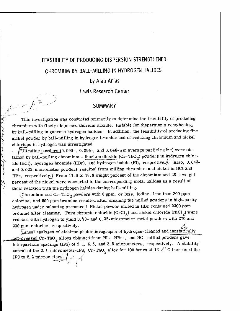
r -" SUMMARY
H "' This investigation was conducted primarily to determine the feasibility of producing kj chromium with finely dispersed thorium dioxide, suitable for dispersion strengthening,
by ball-milling in gaseous hydrogen halides. In addition, the feasibility of producing fine nickel powder by ball-milling in hydrogen bromide and of reducing chromium and nickel
chlorides in hydrogen was investigated. ffTMraiine powders JO. 090-, 0.084-, and 0.046- jxm average particle size) were ob-
^ tained by ball-milling chromium - thorhamjdoxide (Cr-Th02) powders in hydrogen chlor- 1 ide (HC1), hydrogen bromide (HBr), and hydrogen iodide (HI), respectively; Also, 0.043- $ and 0. 023-micrometer powders resulted from milling chromium and nickel in HC1 and \ HBr, respectively.! From 11. 6 to 18. 9 weight percent of the chromium and 26. 5 weight
^; percent of the nickel were converted to the corresponding metal halides as a result of their reaction with the hydrogen halides during ball-milling.
IChromium and Cr-Th02 powders with 6 ppm, or less, iodine, less than 200 ppm chlorine, and 500 ppm bromine resulted after cleaning the milled powders in high-purity hydrogen under pulsating pressure^ Nickel powder milled in HBr contained 2300 ppm bromine after cleaning. Pure chromic chloride (CrClg) and nickel chloride (NiCl2) were reduced with hydrogen to yield 0. 78- and 0. 35-micrometer metal powders with 270 and
200 ppm chlorine, respectively. (\ [Lineal analyses of electron photomicrographs of hydrogen-cleaned and isostatically
^hot-pressed.Cr-ThOo alloys obtained from HI-, HBr-, and HC1-milled powders gave interparticle spacings (IPS) of 2. 1, 6. 5, and 3. 5 micrometers, respectively. A stability anneal of the 2. 1-micrometer-IPS, Cr-Th02 alloy for 100 hours at 1318° C increased the
IPS to 5. 2 micrometersjf j?,.,y/
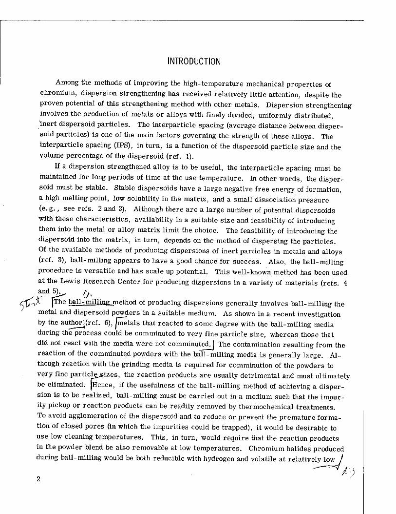
INTRODUCTION
Among the methods of improving the high-temperature mechanical properties of chromium, dispersion strengthening has received relatively little attention, despite the proven potential of this strengthening method with other metals. Dispersion strengthening involves the production of metals or alloys with finely divided, uniformly distributed, inert dispersoid particles. The interparticle spacing (average distance between disper- soid particles) is one of the main factors governing the strength of these alloys. The interparticle spacing (IPS), in turn, is a function of the dispersoid particle size and the volume percentage of the dispersoid (ref. 1).
If a dispersion strengthened alloy is to be useful, the interparticle spacing must be maintained for long periods of time at the use temperature. In other words, the disper- soid must be stable. Stable dispersoids have a large negative free energy of formation, a high melting point, low solubility in the matrix, and a small dissociation pressure (e. g., see refs. 2 and 3). Although there are a large number of potential dispersoids with these characteristics, availability in a suitable size and feasibility of introducing them into the metal or alloy matrix limit the choice. The feasibility of introducing the dispersoid into the matrix, in turn, depends on the method of dispersing the particles. Of the available methods of producing dispersions of inert particles in metals and alloys (ref. 3), ball-milling appears to have a good chance for success. Also, the ball-milling procedure is versatile and has scale up potential. This well-known method has been used at the Lewis Research Center for producing dispersions in a variety of materials (refs. 4 and 5)^ ^
Cy.nA |The ball-milling method of producing dispersions generally involves ball-milling the metal and dispersoid powders in a suitable medium. As shown in a recent investigation by the author](ref. 6), Jmetals that reacted to some degree with the ball-milling media during the process could be comminuted to very fine particle size, whereas those that did not react with the media were not comminuted. ] The contamination resulting from the reaction of the comminuted powders with the ball-milling media is generally large. Al- though reaction with the grinding media is required for comminution of the powders to very fine particlg>izes, the reaction products are usually detrimental and must ultimately be eliminated. jHence, if the usefulness of the ball-milling method of achieving a disper- sion is to be realized, ball-milling must be carried out in a medium such that the impur- ity pickup or reaction products can be readily removed by thermochemical treatments. To avoid agglomeration of the dispersoid and to reduce or prevent the premature forma- tion of closed pores (in which the impurities could be trapped), it would be desirable to use low cleaning temperatures. This, in turn, would require that the reaction products in the powder blend be also removable at low temperatures. Chromium halides produced during ball-milling would be both reducible with hydrogen and volatile at relatively low /
2
/temperatures. Preliminary experiments in which chromium was ball-milled in hydrogen halide gases yielded fine-powdered chromium contaminated with chromium halides^ It was surmised that the reduction of halides formed during ball-milling might be carried out without excessive agglomeration of intentionally added oxides.
/The present investigation was conducted to determine the feasibility of producing chromium with finely dispersed thorium dioxide, suitable for dispersion strengthening, by ball-milling in gaseous hydrogen halides. / It was also intended to determine the high- temperature stability of some of the resulting consolidated products and, in addition, to evaluate the effectiveness of some processing techniques and the use of metal halides as
starting materials. fbforder to carry out the objectives of this investigation, chromium and thorium di-
oxide powders were ball-milled in gas-tight ball mills provided with pressure gages. Hydrogen chloride, hydrogen bromide, and hydrogen iodide gases under pressure were used as grinding media. In addition, because of the possible use of the method for nickel- chromium alloys, the feasibility of comminuting nickel alone by ball-milling in hydrogen bromide was investigated^ Chemical, surface-area, and X-ray diffraction analyses of the ball-milled powders we£g*carried out. Ball-milled powders were cleaned by heating them in flowing hydrogen. [Since on ball-milling in hydrogen halides, the halides of the ball- milled powders are formed, the feasibility of reducing chromium trichloride and nickel dichloride by heating them in flowing hydrogen was also investigated^ Z^^-r/
The cleaned Cr-Th02 alloys were consolidated by hot-presötng. The microstructures of all the alloys were investigated, and the microstructural stability of one of the consoli-
dated Cr-Th02 alloys was studied.
MATERIALS, EQUIPMENT, AND PROCEDURES
Materials
The materials used in this investigation (shown in table I) were high-purity electro- lytic chromium flake; nickel powder; anhydrous chromic chloride (CrClg); anyhydrous nickel chloride (NiCl2); gaseous hydrogen chloride, hydrogen bromide, and hydrogen iodide; high-purity argon; and colloidal thorium dioxide. The chromium powder used in this investigation was made by hammer-milling high-purity electrolytic chromium flake under argon until the powder passed a 30-mesh sieve. The chemical analyses (or manu- facturer's specifications) and purities of the raw materials used are also given in table I.
Equipment
Three pieces of specialized equipment were used in this investigation, a ball mill with pressure gage (fig. 1), a rig for evacuating the ball mills and pressurizing them with hydrogen halides (fig. 2), and a retort for cleaning the ball-milled powders in hydrogen (fig. 3). The retort is part of an overall hydrogen cleaning rig shown in figure 4. De- tailed descriptions of this specialized equipment follow.
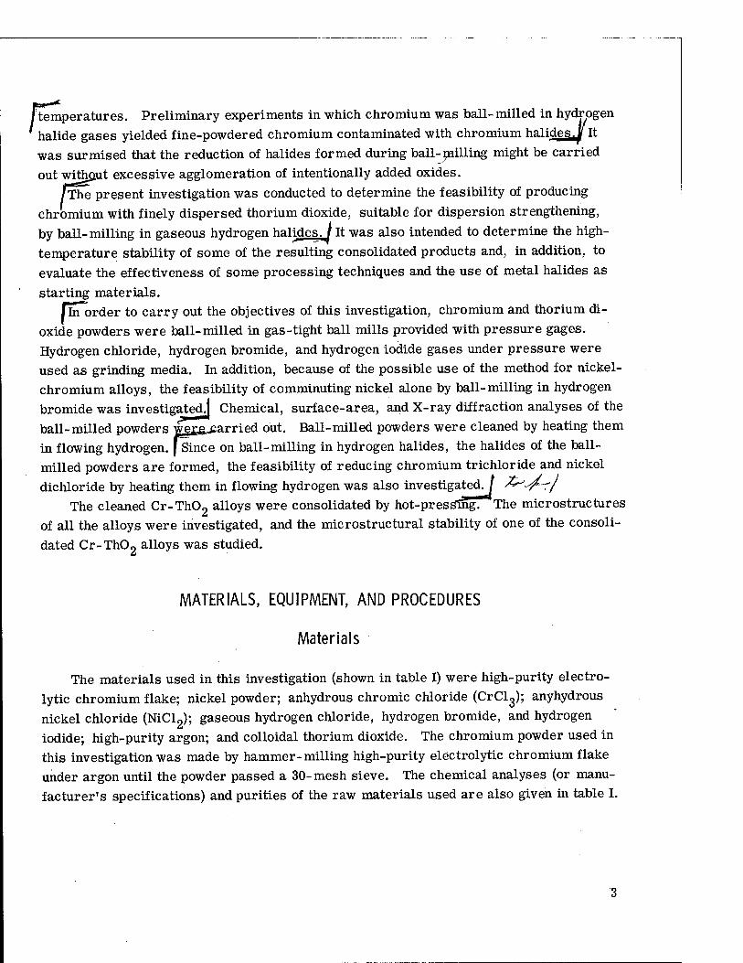
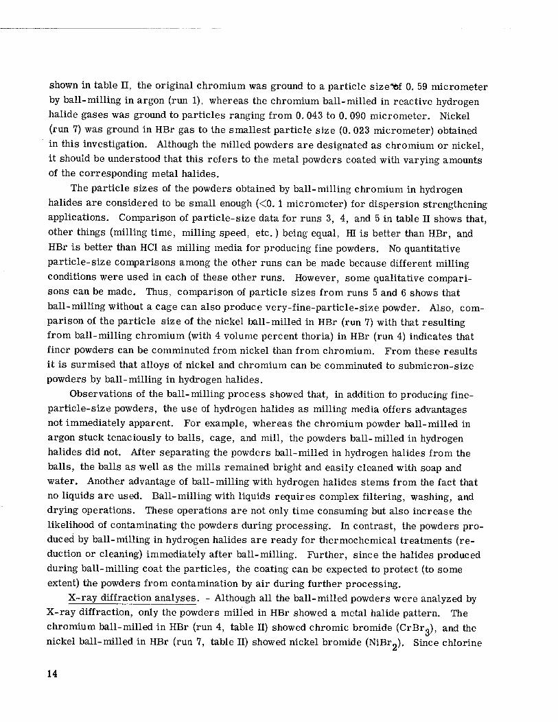
Ball mills and balls. - The type of ball mill used in this investigation is shown in figure 1. The mills were made from type 410 stainless steel and have a nominal inside diameter of 10. 2 centimeters and a capacity of approximately 1580 cubic centimeters. The covers for the mills have fluorocarbon O-ring gaskets to provide a gas-tight seal.
5 2 The mills can be pressurized to approximately 20 atmospheres (20x10 N/m ) without leaking. The ball-mill pressure can be monitored with a 7. 5-centimeter-diameter, stainless-steel gage attached to the ball-mill cover. The as-calibrated accuracy of these gages is better than 0. 035 atmosphere (3500 N/m ). Vacuum valves are used either for evacuating the mills or for pressurizing them with the gases used as ball-milling media.
In some of the ball-milling runs a cage was used for the balls (see fig. 1). This
Y Ball charge
/Ball-mill cover
coupling
Ball-mill body^'
Loose-fitting cage
CD-I006I-I7 Pressure gage
Vacuum valve -
-Tightening screw
Figure 1. - Ball mill with pressure gage and cage.
cylindrical cage was made from expanded, type 304 stainless-steel sheet. The outside diameter of the cage is about 3 millimeters smaller than the inside diameter of the ball mill, and the ends of the cage clear the top and bottom of the ball mill by about 0. 8 milli- meter. The openings of the cage are about 5 millimeters wide, so that the smallest balls used did not touch the inside diameter of the ball mill. In operation, the cage treads on the internal surface of the mill and in so doing scrapes the powder from the ball-mill walls, preventing its accumulation and subsequent caking. The runs in which the cage
was used are indicated in table II. The balls used for ball-milling were type 316 stainless steel. Only two sizes of
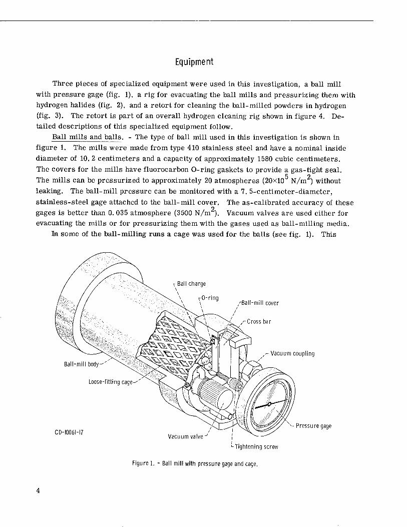
balls, 12. 6 and 6. 3 millimeters nominal diameter, were used. Rig for pressurizing ball mills with hydrogen halides. - The ball mills were evacu-
ated and then pressurized with the hydrogen halides used as ball-milling media with the rig shown schematically in figure 2. For safety, the pressurizing operation was carried out inside an argon- or helium-filled glove box. A similar arrangement was used for evacuating and then pressurizing the ball mill for the run with argon.
To glove-box vacuum system-7 Glove box^ i
Glove-box door-i
Yzz.
<-Absorbent(Li2C03orKOH)
Vacuum valve- i
Ball-mill gage-' (X
Ball mill-'
Pressure regulator
r- Inlet valve
Check valve •
Ball-mill vacuum valve
Hydrogen halide tankJ
7ZZZ
Vacuum valve
; Glove-box / argon inlets
3XJZ3'
X /-To auxiliary vacuum pump
Figure 2. - System for pressurizing ball mills with hydrogen halides.
Bypass valve■
Flexible metal hose
Hydrogen inlet-^fzgjjgffl H^MJm
~Y-- Vacuum coupling
5 Vacuum feedthrough
jo©3' Inlet valve
Pressure gage
Cooling-water in
Hydrogen outlet
valve
J /Cooling-water outlet
Vacuum feedth rough
Retort cover
Cooling coil
Hydrogen inlet and tjH l thermocouple tube ;u, vvv.
Radiation shields —
Thermocouple — — -^
Boat for powder—--..£
Boat base —
;>-Radiation shield separators
A y— Retort body
r
Figure 3. - Retort assembly.
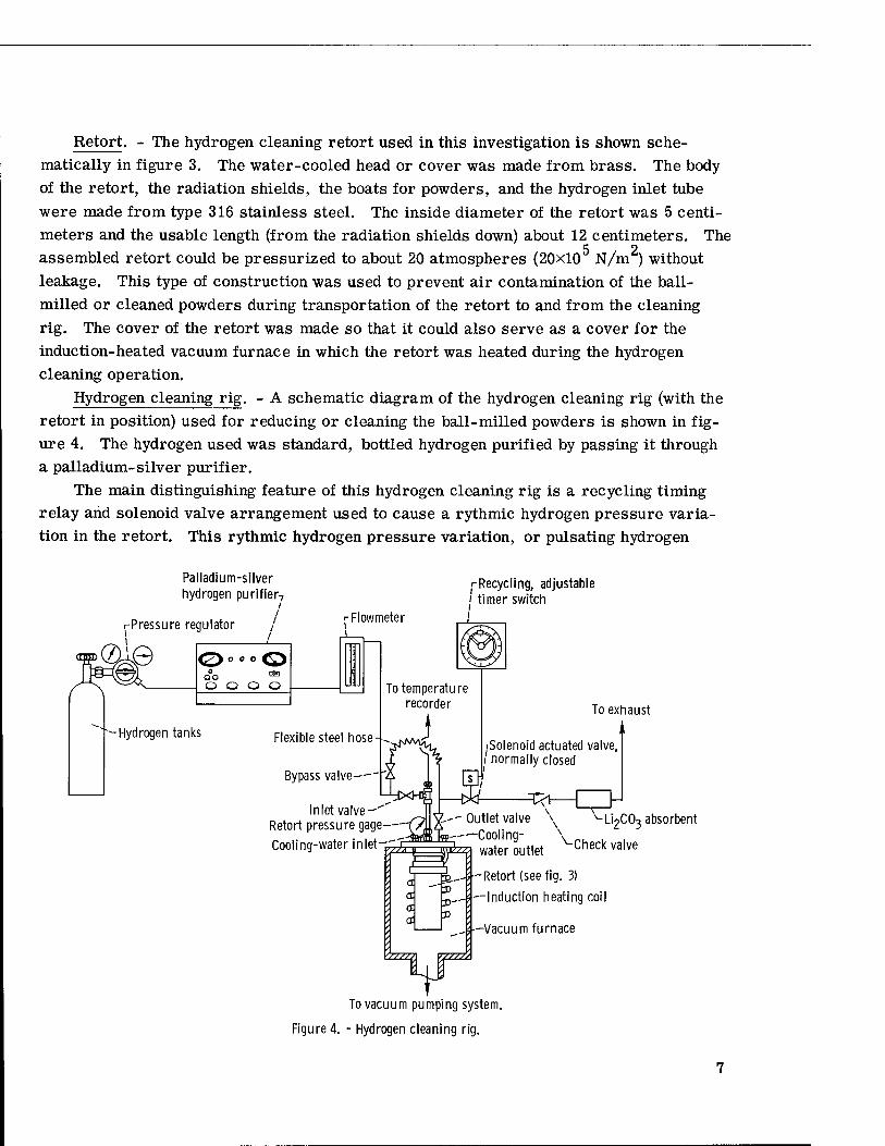
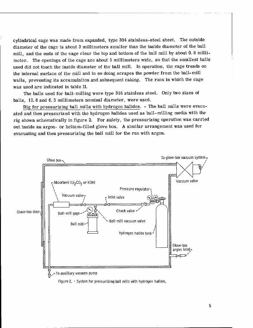
Retort. - The hydrogen cleaning retort used in this investigation is shown sche- matically in figure 3. The water-cooled head or cover was made from brass. The body of the retort, the radiation shields, the boats for powders, and the hydrogen inlet tube were made from type 316 stainless steel. The inside diameter of the retort was 5 centi- meters and the usable length (from the radiation shields down) about 12 centimeters. The assembled retort could be pressurized to about 20 atmospheres (20x10 N/m ) without leakage. This type of construction was used to prevent air contamination of the ball- milled or cleaned powders during transportation of the retort to and from the cleaning rig. The cover of the retort was made so that it could also serve as a cover for the induction-heated vacuum furnace in which the retort was heated during the hydrogen cleaning operation.
Hydrogen cleaning rig. - A schematic diagram of the hydrogen cleaning rig (with the retort in position) used for reducing or cleaning the ball-milled powders is shown in fig- ure 4. The hydrogen used was standard, bottled hydrogen purified by passing it through a palladium-silver purifier.
The main distinguishing feature of this hydrogen cleaning rig is a recycling timing relay and solenoid valve arrangement used to cause a rythmic hydrogen pressure varia- tion in the retort. This rythmic hydrogen pressure variation, or pulsating hydrogen
Palladium-silver hydrogen purifier7
Flowmeter
/-Recycling, adjustable ' timer switch
To temperature recorder
J
Inlet valve- Retort pressure gage
Cooling-water in let-^
To exhaust
iSolenoid actuated valve, /normally closed
£.-- Outlet valve i<g---—Cooling
U2CO3 absorbent
< ij wi^a water outlet Check valve
re & I r" _-;•
-Retort (see fig. 3)
—Induction heating coil
-Vacuum furnace
To vacuum pumping system.
Figure 4. - Hydrogen cleaning rig.
pressure, was used because it was believed that it would facilitate the removal of reac- tion products from the voids between the powder particles.
The recycling timing switch or relay is adjustable from 0 to 60 minutes in either the on or off position. This timing relay activates or deactivates a normally closed solenoid valve located in the outlet side of the retort. When the solenoid valve is closed, the hy- drogen pressure in the retort builds up to whatever pressure the hydrogen purifier was set to deliver. The time required to reach a given pressure in the retort depends on the characteristics of the purifier used and the impedance of the line between the purifier and the retort. Usually, very little change in the hydrogen flow can be made with the purifier itself except by using purifiers of different capacities. The only variable that can be readily adjusted in the purifier is its inlet pressure which, in turn, determines the puri-
fier outlet pressure or the maximum pressure attainable in the retort. The time required to reach a selected purifier outlet pressure will be determined by the impedance of the line between the purifier and the retort. In this investigation, the impedance was adjusted by means of an inlet valve to the retort (see fig. 4), and the time required to lower the pressure to some preselected value (upon opening the solenoid valve) could be adjusted by means of an outlet valve. Hence, by adjusting the hydrogen pressure inlet to the puri- fier, the on-off cycle of the timer, and the inlet and outlet valves, the hydrogen pressure in the retort could be made to pulsate between preselected values at a predetermined number of cycles per hour. In this study, the rig was always run at 60 pulses per hour with the purifier inlet gage pressure maintained at approximately 4 atmospheres (4x10 N/m ) and the inlet and outlet retort valves adjusted so that the retort gage pressure pulsated between 0. 15 and 1. 1 atmospheres (0. 15x10 and 1. lxlO5 N/m ). In case of power failure, the solenoid valve would close and the retort pressure would build up to almost 4 atmospheres.
Procedures
The procedures used in this investigation are described in the order shown in the flow diagram of figure 5. Unless otherwise noted, all the operations (loading ball mills, ball-milling, unloading ball-milled powders, loading retorts, unloading retorts, taking powder samples, and encapsulating powders for isostatic hot-pressing) were carried out in an argon- or helium-filled glove box.
Loading ball mills. - The metal powders (chromium and nickel) and the thorium di- oxide were weighed on an analytical balance inside a glove box and loaded in the mills, together with the ball charge and cage (if used). In all the runs with chromium and thor- ium dioxide, 141. 7 grams of chromium powder and 8. 23 grams of thorium dioxide were used. This amount of thorium dioxide represents 4 volume percent in the compacted
8

Ball mills loaded with balls and powders in argon- or helium- filled glove box
Ball mills evacuated and pressurized with hydrogen ha 1 ides
Powders ball-milled in argon glove box
1
Ball mills evacuated and repressurized with hydrogen halide as required
Samples of ball-milled powders taken for BET and chemical analyses
Milled powders loaded in retort and cleaned in pulsating hydrogen
Samples of cleaned powders taken for chemical or BET analyses
nieaneri nnwrier'; enr.an-
sulated for hot-pressin
sostatic
g
1 Powders isostatically hot-pressed
1 1
Stability annealing of compacted specimens
Specimens examined by electron mi croscopy
Figure 5. - Flow chart for preparation of chromium with 4 volume percent thorium dioxide dispersoids.
Cr-Th02 alloy. In the runs with either pure chromium or pure nickel, 150. 0 grams of the metal powders were used. The number, size, and weight of the balls used in each run are given in table II. Each of the ball-milling runs has been assigned a number for ease of reference. The same number is used to indicate the subsequent cleaning and hot-
pressing processing steps. The gases used as ball-milling media as well as the approximate maximum gas
pressures are also shown in table II. Ball-milling. - Ball-milling was carried out on a rack placed inside an argon-filled
glove box. All the ball mills were rotated at 100 rpm. During each run, the ball-mill
pressure was monitored. The ball-mill gage pressure during run 1 (with argon) remained constant at the original value (approx. 9 atm). In all runs with hydrogen halides, the ball-mill pressures decreased with time as a result of reaction of the hydrogen halide with the metal powders. At intervals depending on the rate of depletion of the hydrogen halide, the ball mill was removed from the rack, and then evacuated with a mechanical vacuum pump and repressurized with the same gas using the rig shown in figure 2. Each ball-milling run was continued for the time shown in table II.
At the end of each run with hydrogen halides the ball mills were evacuated and opened under argon in a glove box (fig. 2). The ball-milled powders were separated from the balls by sieving. Samples of the powders were taken for chemical analyses and/or surface-area analyses by the BET method (ref. 5). Some of the powders were loaded into thin, glass capillary tubes for X-ray diffraction analyses. The open ends of these capil- lary tubes were sealed with vacuum grease before they were removed from the glove box. The remainder of the powder from each run was kept in a gas-tight, stainless-steel can until ready for cleaning.
The ball-milling of chromium in argon (run 1, table II) was carried out for the pur- pose of comparing the resulting particle size with that obtained by ball-milling in hydrogen chloride (run 2, table II). The use of a cage (fig. 1) was found necessary for ball-milling chromium in argon because without the cage the chromium caked on the ball-mill walls. For this reason, the practice of using a cage for ball-milling in hydrogen halides was continued for some experiments (runs 2 to 5, table II). However, later experiments (runs 6 and 7, table II) showed that the use of a cage was not necessary in order to obtain comminution of the powders to very small particle sizes during ball-milling in hydrogen halides.
Reduction or cleaning in hydrogen. - The use of hydrogen under pulsating pressure for sintering (and presumably, the simultaneous cleaning) of metal powders has been re- ported in the literature (ref. 7). However, the means of obtaining the pulsating pressure were not described.
In the present investigation, for reduction in hydrogen, an estimated 10 to 30 grams of a given powder were placed in a stainless-steel boat and weighed on an analytical bal- ance in the glove box. The boat was placed in the retort shown in figure 3; the retort was closed with its cover and then pressurized with about 1 gage atmosphere (10 N/m ) of helium. The retort was checked for leaks with a mass-spectrometer-type leak detector. If no leaks were found, the retort was placed in the induction-heated furnace and connected to the hydrogen and cooling water lines, as shown in figure 4. The bypass valve was opened, and the lines were purged with hydrogen for about 15 minutes. Then the bypass valve was closed, and the inlet and outlet valves were opened and adjusted so that with the recycling timing relay in operation the retort hydrogen pressure pulsated between 0. 15 and 1. 1 atmospheres (0. 15x10 and 1. 1x10 N/m ). The furnace was evacuated,
10

and the power input to the induction-heating coil was adjusted so as to obtain the desired operating temperature. This temperature was monitored with a Chromel-Alumel thermo- couple extending inside the powder boat and connected to a recording potentiometer. The temperatures for each of the cleaning runs are shown in table III and are estimated to be accurate within ±5° C. Suitable operating-temperature ranges for each type of hydrogen halide ball-milled chromium powder were established by preliminary trial runs in which a fixed amount of powder was heated for 3-hour intervals at successively higher tempera- tures. The weight loss at each temperature was determined by weighing the boat and powder after each run. The effect of cleaning time (at 625° C) on the weight lost by the HC1- ball -milled chromium from run 2 (table II) was also determined. The temperature used for cleaning the HBr-milled nickel powder was found to be satisfactory (suitable reduction rates with no caking) during the first trial run at 350° C. In the actual runs reported in table HI, the boats were loaded with powders and cleaned in a manner similar to that used in the preliminary trial runs. The retorts were removed from the cleaning rig at various intervals and taken to the glove box where the powders in the boats were weighed. This procedure of cleaning and weighing was continued until the powders no longer showed a weight loss. Samples of the cleaned powders were taken for chemical analyses and/or surface-area analyses by the BET method (ref. 8). Samples for oxygen analyses were placed in tin capsules and sealed. The remainder of the cleaned powders were used for making hot-pressed specimens.
Reduction of chromic chloride and nickel chloride in hydrogen. - The feasibility of obtaining chromium and nickel powders by reduction of their chlorides in hydrogen was also investigated because, if successful, it would offer an alternative approach to the pro- duction of dispersion strengthened chromium and nickel or their alloys. This new ap- proach would be to ball-mill the metal chloride and the dispersoid (instead of the metal and dispersoid) followed by reduction of the chloride in hydrogen.
About 30-gram batches of as-received anhydrous chromic chloride (CrClo) and anhy- drous nickel chloride (NiCU) were also reduced to the metal in pulsating hydrogen. The chlorides were loaded in stainless-steel boats in the as-received condition and weighed on an analytical balance. The boats were loaded in retorts and cleaned in hydrogen by the same method used for the ball-milled powders. Chemical analyses and surface-area analyses (by the BET method) were also carried out on the resulting powders.
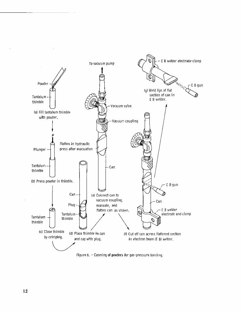
Encapsulation of cleaned powders. - The cleaned Cr-ThO« powders were encapsulated for isostatic hot-pressing as shown in figure 6. The powders were first placed in tanta- lum thimbles approximately 9 millimeters in outside diameter and about 5 centimeters long. The powder in each of the thimbles was packed by pressing it at low pressure (about 25 kilograms per square centimeter (245 N/cra )) in a small hydraulic press. The top of each thimble was closed by crimping the wall (approx. 0. 01 millimeter thick). Each loaded thimble was placed in a stainless-steel hot-pressing can or tube approxi-
11
Powder -
Tantalum - thimble
To vacuum pump
t - E B welder electrode-clamp
(a) Fill tantalum thimble with powder.
I Plunger
Tantalum thimble
Flatten in hydraulic
press after evacuation
E B gun
(g) Weld lips of flat section of can in E B welder.
Vacuum valve
-Vacuum coupling
(b) Press powder in thimble.
(Si
Tantalum -- thimble
Can —-
Plug-.
Tantalum-H thimble
■--Can
kam) (e) Connect can to
vacuum coupling,
evacuate, and flatten can as shown.
km*?
— E B gun
/- E B welder electrode and clamp
(c) Close thimble (d) P,ace thimble in can by crimping. and cap witn p,ug.
(f) Cut off can across flattened section
in electron beam (E B) welder.
Figure 6. - Canning of powders for gas-pressure bonding.
12

mately 17. 5 millimeters in outside diameter and 17. 5 centimeters long. The thimble was capped with a stainless-steel, loose-fitting plug. A vacuum coupling with valve (see fig. 6(e)) was connected to each tube, and the tube was evacuated to less than 0.0001 torr. While still connected to the vacuum system, each tube was placed in a small hydraulic press and flattened as shown in figure 6(e). The vacuum valve was then closed, and the tube was taken to the electron beam welder for cutting and welding as shown in figures 6(f) and (g). This encapsulation method was used in order to prevent contamination of the powders with air.
Hot-pressing. - The encapsulated powders were isostatically hot-pressed in a high- pressure, high-temperature autoclave (or isostatic gas-pressure bonding furnace) where pressure was applied with helium. All the cans or tubes used to obtain the Cr-ThO„
o 5 specimens listed in table III were hot-pressed at 1093 C and 747 atmospheres (757x10 o
N/m ) for 2 hours. These hot-pressing conditions were selected on the basis of previous work with chromium reported in the literature (ref. 9). All the compacted Cr-ThO„ al- loys were chemically analyzed for thorium and oxygen. Electron photomicrographs of the hot-pressed specimens were obtained by using a replication technique.
Stability anneals. - The Cr-Th02 alloy obtained by cleaning and hot-pressing the powder from ball-milling run 5 (table II) was given stability anneals in helium at a gage
5 2 pressure of about 1 atmosphere (10 N/m ) at the temperatures and times shown in table IV. Electron photomicrographs of the annealed materials were taken by using a replication technique.
Interparticle spacings. - Interparticle spacings were determined from the electron photomicrographs by the linear intercept method. Straight lines were drawn at random in the electron photomicrographs, and at least 100 intersections with dispersoid particles were counted to calculate the interparticle spacing.
RESULTS AND DISCUSSION
Powders Produced by Ball-Milling
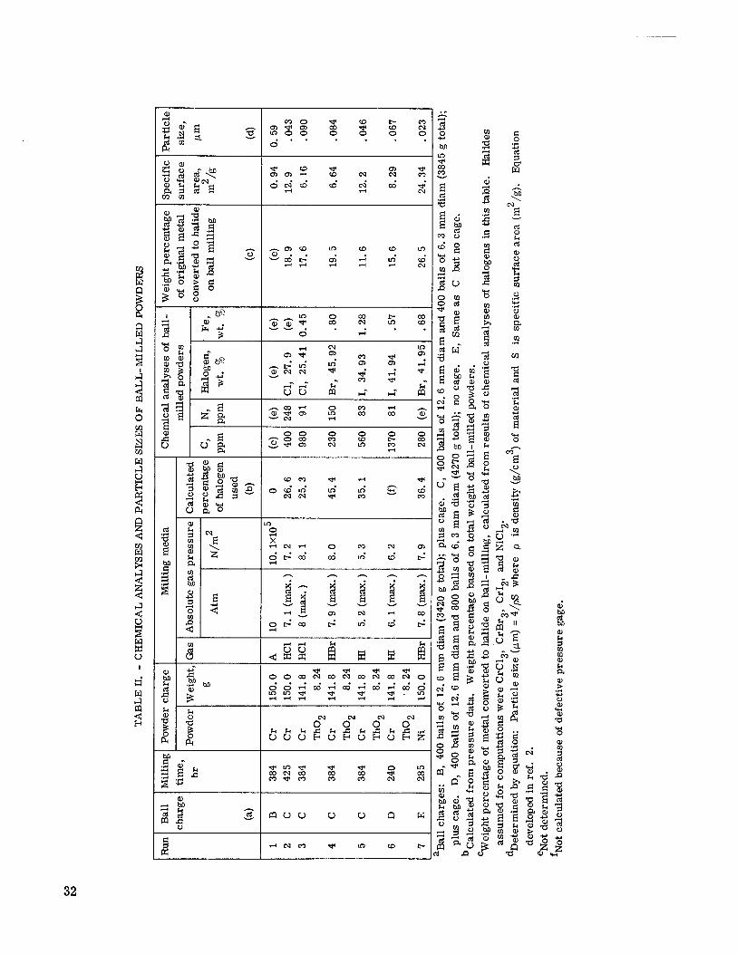
The surface areas and particle sizes of the Cr-ThO«, chromium, and nickel powders obtained by ball-milling in argon and in hydrogen halides are listed in table II. This table also contains the calculated amounts of halogens which reacted with the powders during ball-milling and the chemical analyses of the milled powders. A number has been as- signed to every milling run listed in table II. The powder resulting from each of the runs is designated with the same number in subsequent processing operations.
Particle sizes. - As shown in table I, the original particle sizes of the chromium and nickel powders used in this investigation were 5 and 1. 2 micrometers, respectively. As
13
shown in table II, the original chromium was ground to a particle size^f 0. 59 micrometer by ball-milling in argon (run 1), whereas the chromium ball-milled in reactive hydrogen halide gases was ground to particles ranging from 0. 043 to 0. 090 micrometer. Nickel (run 7) was ground in HBr gas to the smallest particle size (0. 023 micrometer) obtained in this investigation. Although the milled powders are designated as chromium or nickel, it should be understood that this refers to the metal powders coated with varying amounts of the corresponding metal halides.
The particle sizes of the powders obtained by ball-milling chromium in hydrogen halides are considered to be small enough (<0. 1 micrometer) for dispersion strengthening applications. Comparison of particle-size data for runs 3, 4, and 5 in table II shows that, other things (milling time, milling speed, etc.) being equal, HI is better than HBr, and
HBr is better than HC1 as milling media for producing fine powders. No quantitative particle-size comparisons among the other runs can be made because different milling conditions were used in each of these other runs. However, some qualitative compari- sons can be made. Thus, comparison of particle sizes from runs 5 and 6 shows that ball-milling without a cage can also produce very-fine-particle-size powder. Also, com- parison of the particle size of the nickel ball-milled in HBr (run 7) with that resulting from ball-milling chromium (with 4 volume percent thoria) in HBr (run 4) indicates that finer powders can be comminuted from nickel than from chromium. From these results it is surmised that alloys of nickel and chromium can be comminuted to submicron-size powders by ball-milling in hydrogen halides.
Observations of the ball-milling process showed that, in addition to producing fine- particle-size powders, the use of hydrogen halides as milling media offers advantages not immediately apparent. For example, whereas the chromium powder ball-milled in argon stuck tenaciously to balls, cage, and mill, the powders ball-milled in hydrogen halides did not. After separating the powders ball-milled in hydrogen halides from the balls, the balls as well as the mills remained bright and easily cleaned with soap and water. Another advantage of ball-milling with hydrogen halides stems from the fact that no liquids are used. Ball-milling with liquids requires complex filtering, washing, and drying operations. These operations are not only time consuming but also increase the likelihood of contaminating the powders during processing. In contrast, the powders pro- duced by ball-milling in hydrogen halides are ready for thermochemical treatments (re- duction or cleaning) immediately after ball-milling. Further, since the halides produced during ball-milling coat the particles, the coating can be expected to protect (to some extent) the powders from contamination by air during further processing.
X-ray diffraction analyses. - Although all the ball-milled powders were analyzed by X-ray diffraction, only the powders milled in HBr showed a metal halide pattern. The chromium ball-milled in HBr (run 4, table II) showed chromic bromide (CrBr3), and the nickel ball-milled in HBr (run 7, table II) showed nickel bromide (NiBr«). Since chlorine
14
is more reactive than bromine, it is surmised that the HCl-milled chromium powders have the chlorine in the form of CrCl«. Further, since chromic iodide (Crl„) decomposes into chromous iodide (Crl„) and iodine (I„) at about 350° C (ref. 10) and no condensations of free iodine were noted during thermochemical treatments (to be described later), it is surmised that the reaction of hydrogen iodide with chromium during ball-milling pro- duces Crl2<
Reaction of powders with ball-milling media. - The use of hydrogen halide gases as ball-milling media stems from previous work by the author on the role of chemical reac- tions in the comminution of metals and alloys during ball-milling (ref. 6). It was postu- lated in that work that extensive comminution of metals and alloys during ball-milling re- quires their reaction with the grinding media. Hence, the grinding media should be chosen so that the undesirable components in the product of the reaction are easily re- moved from the milled powders by thermochemical treatments. The hydrogen halides used as milling media in this investigation form metal halides during ball-milling ac- cording to the following chemical equations:
2Cr(s) + 6HX(g) = 2CrX3(s) + 3H2(g) (1)
Ni(s) + 2HX(g) = NiX2(s) + H2(g) (2)
where X is one of the halogens. A knowledge of the amounts of halogens reacted with the milled powders is of sig-
nificance in subsequent reducing (or cleaning) operations. The halogen reacted with the powders during ball-milling can be determined either from the amounts of hydrogen halide used up or by chemical analyses of the ball-milled powders.
The amounts of hydrogen halide used up during ball-milling can be readily calculated from the change in ball-mill pressure AP (or from their sum 2 AP) and from the free volume of the mill V (where V is 986 to 1075 cubic centimeters, depending on the mill). These values are substituted in the following (Boyle's law) equation:
2£>P(atm) x V(liters) x M Y = Total grams of halogen used = (3)
22. 4 liters-atm/mole
where M is the gram atomic weight of the halogen. The factor 2 stems from the fact that when 2 moles of hydrogen halide react with the metal being ball-milled, 1 mole of hydrogen gas is formed, as shown by the chemical equations (1) and (2).
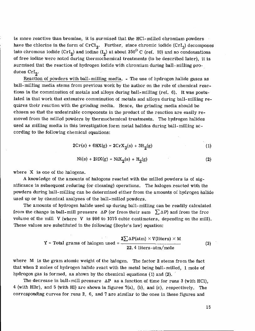
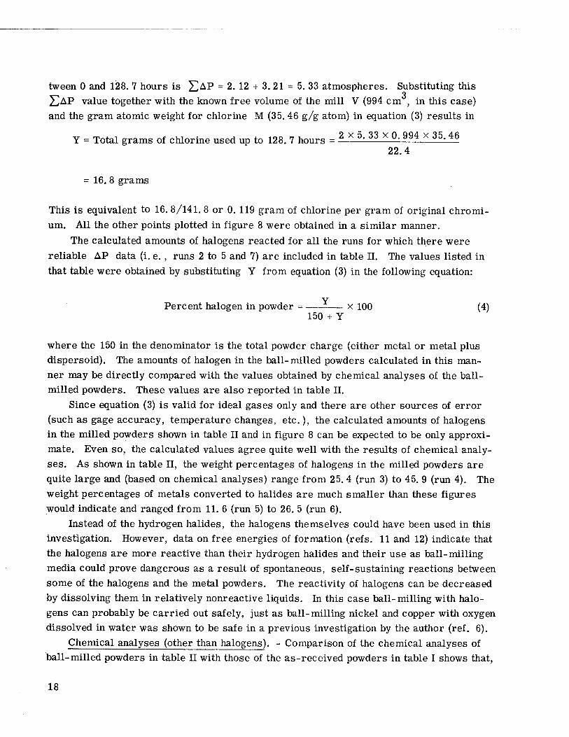
The decrease in ball-mill pressure AP as a function of time for runs 3 (with HC1), 4 (with HBr), and 5 (with HI) are shown in figures 7(a), (b), and (c), respectively. The corresponding curves for runs 2, 6, and 7 are similar to the ones in these figures and
15
(b) Hydrogen bromide (run 4, table II).
6xl05
6r— ♦ Ball-mill evacuated and refilled with corresponding hydrogen halide
120 160 200 240 280 320 360 400 Ball-milling time, hr
(c) Hydrogen iodide (run 5, table II).
Figure 7. - Decrease in mill pressure on ball-milling Cr-Th02 powders in hydrogen halides.
16
for this reason are not shown. In addition, the AP data for run 6 were not used for cal- culations because the pressure gage was found to be defective at the end of the run. In contrast to the quite large decreases in ball-mill pressure which occur during ball- milling in hydrogen halides, no significant change in ball-mill pressure was observed during the ball-milling of chromium in argon (run 1).
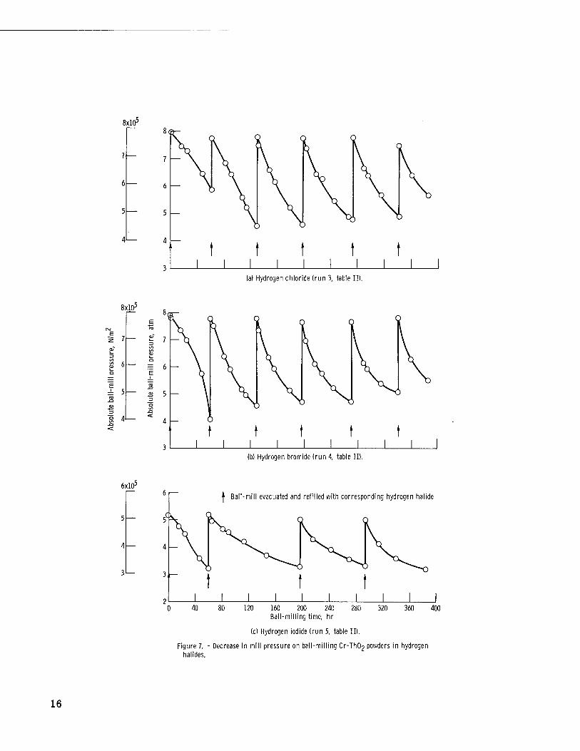
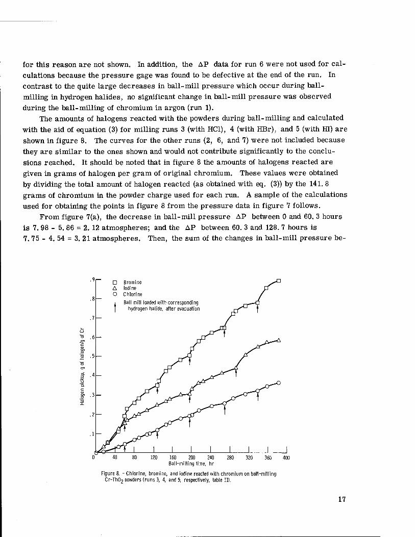
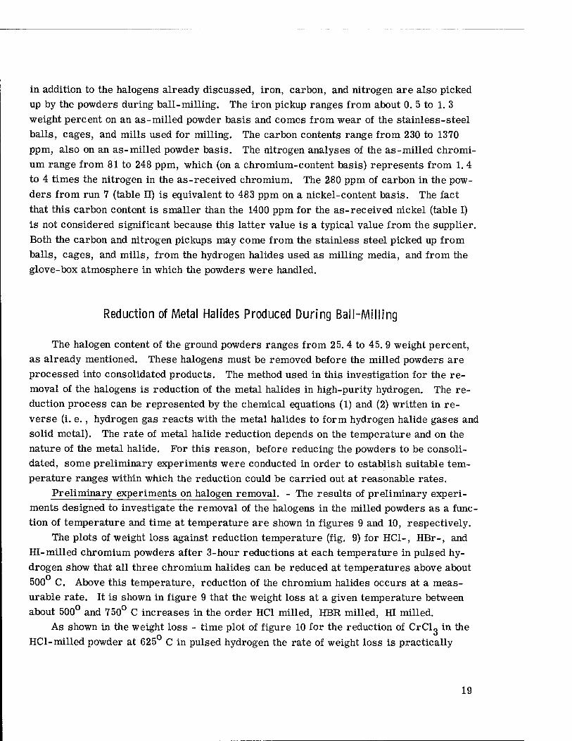
The amounts of halogens reacted with the powders during ball-milling and calculated with the aid of equation (3) for milling runs 3 (with HC1), 4 (with HBr), and 5 (with HI) are shown in figure 8. The curves for the other runs (2, 6, and 7) were not included because they are similar to the ones shown and would not contribute significantly to the conclu- sions reached. It should be noted that in figure 8 the amounts of halogens reacted are given in grams of halogen per gram of original chromium. These values were obtained by dividing the total amount of halogen reacted (as obtained with eq. (3)) by the 141. 8 grams of chromium in the powder charge used for each run. A sample of the calculations used for obtaining the points in figure 8 from the pressure data in figure 7 follows.
From figure 7(a), the decrease in ball-mill pressure AP between 0 and 60. 3 hours is 7. 98 - 5. 86 = 2. 12 atmospheres; and the AP between 60. 3 and 128. 7 hours is 7. 75 - 4. 54 = 3. 21 atmospheres. Then, the sum of the changes in ball-mill pressure be-
.9
g1 .3-
□ Bromine A Iodine O Chlorine
Ball mill loaded with corresponding hydrogen halide, after evacuation
120 160 200 240 Ball-milling time, hr
280 320 360 400
Figure 8. -Chlorine, bromine, and iodine reacted with chromium on ball-milling Cr-Th02 powders (runs 3, 4, and 5, respectively, table II).
17
tween 0 and 128. 7 hours is J^AV = 2. 12 + 3. 21 = 5. 33 atmospheres. Substituting this X^AP value together with the known free volume of the mill V (994 cm , in this case) and the gram atomic weight for chlorine M (35. 46 g/g atom) in equation (3) results in
Y = Total grams of chlorine used up to 128. 7 hours = —X 5' 33 x °-"4 x35.46 22.4
= 16. 8 grams
This is equivalent to 16. 8/141. 8 or 0. 119 gram of chlorine per gram of original chromi- um. All the other points plotted in figure 8 were obtained in a similar manner.
The calculated amounts of halogens reacted for all the runs for which there were reliable AP data (i. e., runs 2 to 5 and 7) are included in table II. The values listed in that table were obtained by substituting Y from equation (3) in the following equation:
Y Percent halogen in powder = x 100 (4)
150 + Y
where the 150 in the denominator is the total powder charge (either metal or metal plus dispersoid). The amounts of halogen in the ball-milled powders calculated in this man- ner may be directly compared with the values obtained by chemical analyses of the ball- milled powders. These values are also reported in table II.
Since equation (3) is valid for ideal gases only and there are other sources of error (such as gage accuracy, temperature changes, etc.), the calculated amounts of halogens in the milled powders shown in table II and in figure 8 can be expected to be only approxi- mate. Even so, the calculated values agree quite well with the results of chemical analy- ses. As shown in table II, the weight percentages of halogens in the milled powders are quite large and (based on chemical analyses) range from 25. 4 (run 3) to 45. 9 (run 4). The weight percentages of metals converted to halides are much smaller than these figures would indicate and ranged from 11. 6 (run 5) to 26. 5 (run 6).
Instead of the hydrogen halides, the halogens themselves could have been used in this investigation. However, data on free energies of formation (refs. 11 and 12) indicate that the halogens are more reactive than their hydrogen halides and their use as ball-milling media could prove dangerous as a result of spontaneous, self-sustaining reactions between some of the halogens and the metal powders. The reactivity of halogens can be decreased by dissolving them in relatively nonreactive liquids. In this case ball-milling with halo- gens can probably be carried out safely, just as ball-milling nickel and copper with oxygen dissolved in water was shown to be safe in a previous investigation by the author (ref. 6).
Chemical analyses (other than halogens). - Comparison of the chemical analyses of ball-milled powders in table II with those of the as-received powders in table I shows that,
18
in addition to the halogens already discussed, iron, carbon, and nitrogen are also picked up by the powders during ball-milling. The iron pickup ranges from about 0. 5 to 1. 3 weight percent on an as-milled powder basis and comes from wear of the stainless-steel balls, cages, and mills used for milling. The carbon contents range from 230 to 1370 ppm, also on an as-milled powder basis. The nitrogen analyses of the as-milled chromi- um range from 81 to 248 ppm, which (on a chromium-content basis) represents from 1. 4 to 4 times the nitrogen in the as-received chromium. The 280 ppm of carbon in the pow- ders from run 7 (table II) is equivalent to 483 ppm on a nickel-content basis. The fact that this carbon content is smaller than the 1400 ppm for the as-received nickel (table I) is not considered significant because this latter value is a typical value from the supplier. Both the carbon and nitrogen pickups may come from the stainless steel picked up from balls, cages, and mills, from the hydrogen halides used as milling media, and from the glove-box atmosphere in which the powders were handled.
Reduction of Metal Halides Produced During Ball-Milling
The halogen content of the ground powders ranges from 25. 4 to 45. 9 weight percent, as already mentioned. These halogens must be removed before the milled powders are processed into consolidated products. The method used in this investigation for the re- moval of the halogens is reduction of the metal halides in high-purity hydrogen. The re- duction process can be represented by the chemical equations (1) and (2) written in re- verse (i. e., hydrogen gas reacts with the metal halides to form hydrogen halide gases and solid metal). The rate of metal halide reduction depends on the temperature and on the nature of the metal halide. For this reason, before reducing the powders to be consoli- dated, some preliminary experiments were conducted in order to establish suitable tem- perature ranges within which the reduction could be carried out at reasonable rates.
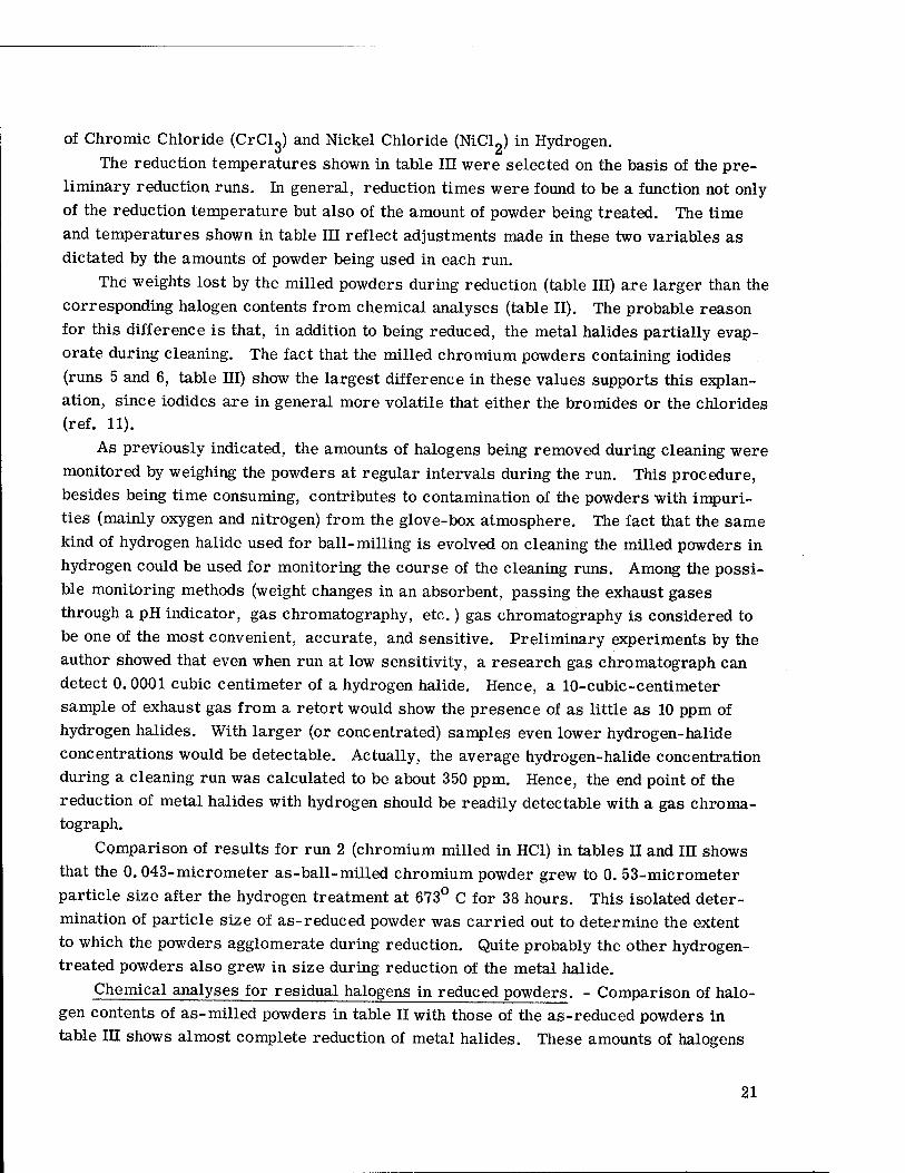
Preliminary experiments on halogen removal. - The results of preliminary experi- ments designed to investigate the removal of the halogens in the milled powders as a func- tion of temperature and time at temperature are shown in figures 9 and 10, respectively.
The plots of weight loss against reduction temperature (fig. 9) for HC1-, HBr-, and HI-milled chromium powders after 3-hour reductions at each temperature in pulsed hy- drogen show that all three chromium halides can be reduced at temperatures above about 500 C. Above this temperature, reduction of the chromium halides occurs at a meas- urable rate. It is shown in figure 9 that the weight loss at a given temperature between about 500° and 750° C increases in the order HC1 milled, HBR milled, HI milled.
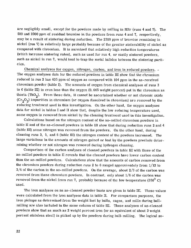
As shown in the weight loss - time plot of figure 10 for the reduction of CrCl„ in the HC1-milled powder at 625 C in pulsed hydrogen the rate of weight loss is practically
19

8 30 —
300 400 500 600 Reduction temperature, °C
900 1000
Figure 9. - Cumulative percent weight loss during hydrogen reduction of chromium pow- ders obtained by ball-milling in hydrogen halides. Reducing conditions: approximately 10 grams of each powder reduced in purified hydrogen pulsating between 1.15 and 2.10 absolute atmospheres (1.16xl05 and 2.12x10-' N/m2 abs); same powder charge was used for all runs with given type of powder; reduction time, 3 hours per run.
10 15 20 Time, hr
25 30
Figure 10. - Effect of reduction time on weight loss for chromium powder reduced in hydrogen at 625° C. Reducing conditions: approximately 10 grams of chromium powder from HCI milling run 2 (see table II); purified hydrogen pulsating between 1.15 and 2.10 absolute atmospheres (1.16x10' and 2.12xl05 N/m2 abs) at 60 pulses per hour.
constant to almost complete removal of the chlorine. The HBr- and HI-milled powders probably behave in a similar manner.
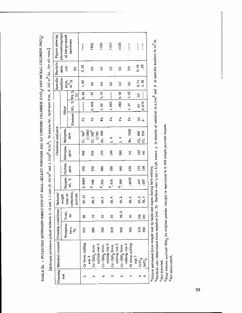
Reduction of halides in powders used for compaction and/or analysis. - The reducing temperature and time and the results of weight loss and chemical analysis of the hydrogen-treated powders are shown in table III. The after-reduction particle size of one of the HCl-milled chromium powders (run 2) is also included in this table. Reduc- tion runs 8 and 9, also shown in table III, were carried out to determine the feasibility of reducing the pure metal halides, and the results are discussed in the section Reduction
20
of Chromic Chloride (CrClg) and Nickel Chloride (NiClJ in Hydrogen. The reduction temperatures shown in table III were selected on the basis of the pre-
liminary reduction runs. In general, reduction times were found to be a function not only of the reduction temperature but also of the amount of powder being treated. The time and temperatures shown in table III reflect adjustments made in these two variables as dictated by the amounts of powder being used in each run.
The weights lost by the milled powders during reduction (table III) are larger than the corresponding halogen contents from chemical analyses (table II). The probable reason for this difference is that, in addition to being reduced, the metal halides partially evap- orate during cleaning. The fact that the milled chromium powders containing iodides (runs 5 and 6, table III) show the largest difference in these values supports this explan- ation, since iodides are in general more volatile that either the bromides or the chlorides (ref. 11).
As previously indicated, the amounts of halogens being removed during cleaning were monitored by weighing the powders at regular intervals during the run. This procedure, besides being time consuming, contributes to contamination of the powders with impuri- ties (mainly oxygen and nitrogen) from the glove-box atmosphere. The fact that the same kind of hydrogen halide used for ball- milling is evolved on cleaning the milled powders in hydrogen could be used for monitoring the course of the cleaning runs. Among the possi- ble monitoring methods (weight changes in an absorbent, passing the exhaust gases through a pH indicator, gas chromatography, etc.) gas chromatography is considered to be one of the most convenient, accurate, and sensitive. Preliminary experiments by the author showed that even when run at low sensitivity, a research gas Chromatograph can detect 0. 0001 cubic centimeter of a hydrogen halide. Hence, a 10-cubic-centimeter sample of exhaust gas from a retort would show the presence of as little as 10 ppm of hydrogen halides. With larger (or concentrated) samples even lower hydrogen-halide concentrations would be detectable. Actually, the average hydrogen-halide concentration during a cleaning run was calculated to be about 350 ppm. Hence, the end point of the reduction of metal halides with hydrogen should be readily detectable with a gas Chroma- tograph.
Comparison of results for run 2 (chromium milled in HC1) in tables II and IE shows that the 0. 043-micrometer as-ball-milled chromium powder grew to 0. 53-micrometer particle size after the hydrogen treatment at 673° C for 38 hours. This isolated deter- mination of particle size of as-reduced powder was carried out to determine the extent to which the powders agglomerate during reduction. Quite probably the other hydrogen- treated powders also grew in size during reduction of the metal halide.
Chemical analyses for residual halogens in reduced powders. - Comparison of halo- gen contents of as-milled powders in table II with those of the as-reduced powders in table III shows almost complete reduction of metal halides. These amounts of halogens
21
are negligibly small, except for the powders made by milling in HBr (runs 4 and 7). The 500 and 2300 ppm of residual bromine in the powders from runs 4 and 7, respectively, may be a result of sintering during reduction. The 2300 ppm of bromine remaining in nickel (run 7) is relatively large probably because of the greater sinterability of nickel as compared with chromium. It is surmised that relatively high reduction temperatures (which increase sintering rates), such as used for run 4, or easily sintered powders, such as nickel in run 7, would tend to trap the metal halides between the sintering parti- cles.
Chemical analyses for oxygen, nitrogen, carbon, and iron in reduced powders. - The oxygen analyses data for the reduced powders in table III show that the chromium reduced in run 2 has 405 ppm of oxygen as compared with 104 ppm in the as-received chromium powder (table I). The amounts of oxygen from chemical analyses of runs 3 to 6 (table in) is even less than the oxygen (0. 665 weight percent) put in the chromium as thoria (ThOg). From these data, it cannot be ascertained whether or not chromic oxide
(Cr2°3^ imPurities in chromium (or oxygen dissolved in chromium) are removed by the reducing treatment used in this investigation. On the other hand, the oxygen analyses data for nickel in tables I and II show that, despite the low reducing temperature used, some oxygen is removed from nickel by the cleaning treatment used in this investigation.
Calculations based on the nitrogen content of the as-milled chromium powders in table II and of the as-cleaned powders in table III show that during reduction runs 2 and 4 (table III) some nitrogen was removed from the powders. On the other hand, during cleaning runs 3, 5, and 6 (table III) the nitrogen content of the powders increased. The large variations in the amounts of nitrogen gained or lost by the powders preclude deter- mining whether or not nitrogen was removed during hydrogen cleaning.
Comparison of the carbon analyses of cleaned powders in table III with those of the as-milled powders in table II reveals that the cleaned powders have lower carbon content than the as-milled powders. Calculations show that the amounts of carbon removed from the chromium powders during reduction runs 2 to 6 ranged approximately from 1/12 to 3/4 of the carbon in the as-milled powders. On the average, about 2/3 of the carbon was removed from these chromium powders. In contrast, only about 1/8 of the carbon was removed from the nickel from run 7, probably because of the low temperature (350° C) used.
The iron analyses on an as-cleaned powder basis are given in table III. These values were calculated from the iron analyses data in table II. For comparison purposes, the iron pickups as determined from the weight lost by balls, cages, and mills during ball- milling are also included in the same column of table III. These analyses of as-cleaned powders show that as much as 2 weight percent iron (or an equivalent of about 3 weight percent stainless steel) is picked up by the powders during ball-milling. The logical so-
22

lution to this iron-pickup problem is to use milling equipment made entirely from, or plated with, chromium.
Reduction of Chromic Chloride (CrC^) and Nickel Chloride (Nicy in Hydrogen
Table in shows the chemical analyses and particle sizes of the chromium and nickel powders obtained by reduction of CrCl, and NiCl«, respectively, in purified, pulsating hydrogen. Reducing temperatures and times at temperature are also included in this table.
The chromium powder obtained (run 8) had a particle size of 0. 78 micrometer, 0.457 weight percent oxygen, 200 ppm residual chlorine, and relatively small amounts of carbon (176 ppm) and nitrogen (149 ppm). The relatively large amount of oxygen in this powder probably originates in the raw CrClo. The particle size of this powder is some- what larger than that of the chromium obtained by milling and cleaning in run 2.
The data for nickel obtained by reduction of NiCl2 (run 9, table III) show that this powder has a fairly small (0. 35 jum) particle size, and only 870 ppm oxygen, 120 ppm carbon, 190 ppm sulfur, and 270 ppm residual chlorine. As far as the chemical analysis is concerned, this nickel powder compares favorably with that obtained by ball-milling and cleaning (run 7, table III).
The idea behind these halide reduction experiments was that, if these chlorides could be hydrogen reduced without excessive agglomeration and contamination, it should be pos- sible to make dispersion strengthened alloys by direct ball-milling of halides with the dispersoid, followed by hydrogen cleaning of the powder mixture. This procedure would not require the somewhat hazardous use of hydrogen halides as milling media. From the results already discussed it appears that the idea is feasible, but it has two main draw- backs. The first drawback is the relatively long times (138 and 160 hrs for Cr and Ni, respectively) required for reduction of the chlorides. These are about 3 to 4 times the time required for cleaning the ball-milled powders. A second drawback is that some of the halides are fairly hygroscopic and must be protected from atmospheric moisture.
The reduction of chromium chlorides with hydrogen and some of the problems asso- ciated with this method of chromium production are discussed in the literature (refs. 13 and 14). The chromium powders produced in this investigation appear to be of about the same purity as the chromium spangles produced by the method of reference 10. It should be noted that, in the methods of chromium chloride reduction described in references 10 and 11, temperatures in excess of 800° C are used, as contrasted with 675 C used in this investigation. Considering the agglomeration of milled chromium powders during hydrogen treatments already discussed, the lower temperatures used in this investigation are preferred.
23

It is surmised that reduction of halides other than chlorides may yield results simi- lar to those obtained by reducing the chlorides, or perhaps even better. This surmise is based on the fact that (from an interparticle spacing standpoint) the chromium powders obtained by ball-milling in HI produce better results than those ball-milled in HC1, as is pointed out in the section Advantages of Hydrogen Iodide Ball-Milled Mateiial.
Isostatically Hot-Pressed Chromium-Thoria Alloys
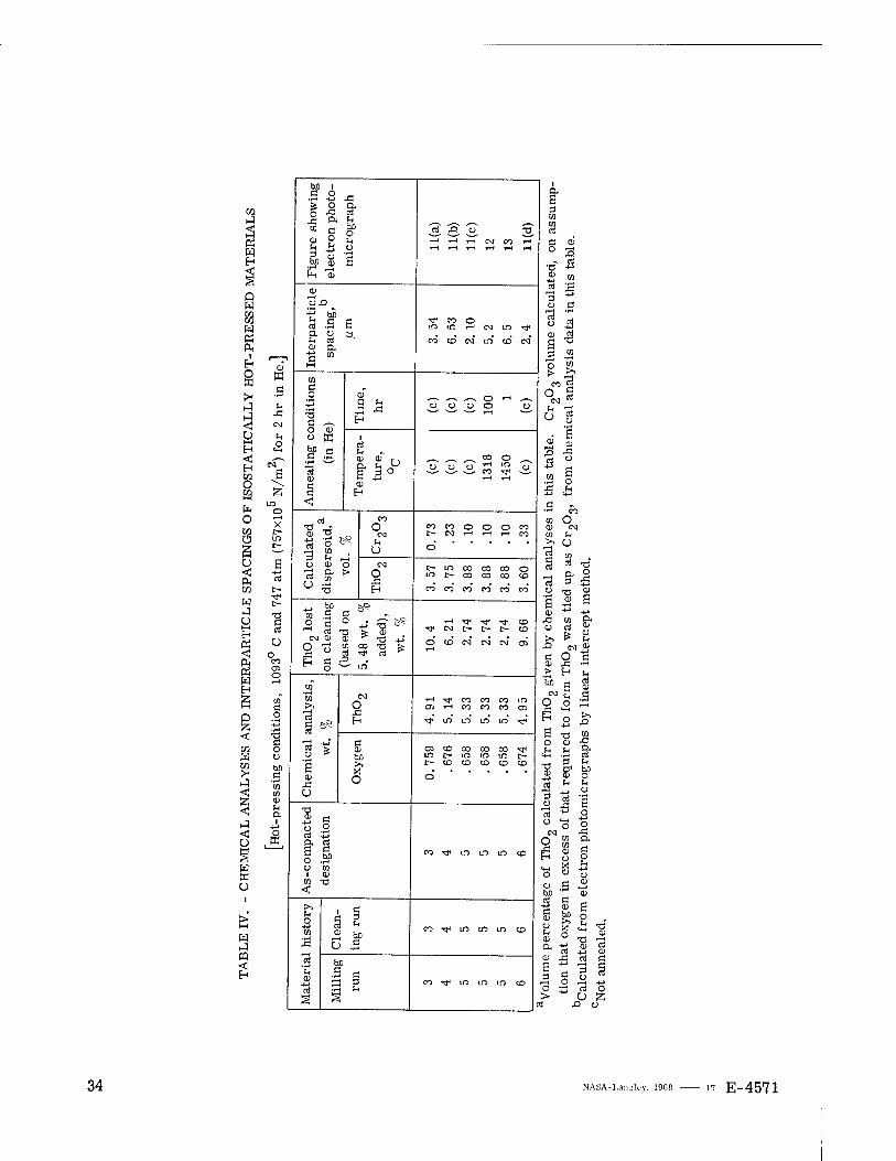
Chemical analyses. - The chemical analyses of the Cr-Th02 compositions obtained by isostatic hot-pressing of the hydrogen-cleaned powders at 1093° C and 747 atmos-
5 2 pheres (757x10 N/m ) for 2 hours are listed in table IV. The volume percentages of ThO„ and Cr~0„ in table IV were calculated from the oxygen and ThO~ given by chemical analyses, on the assumption that the oxygen in excess of that in ThO« is in the form of Cr20„. The sum of these two volume percentages of dispersoids is very close to four. The material from run 5 resulting from ball-milling in HI has the lowest calculated vol- ume percentage of Cr20„. The fact that this material was the one cleaned at the lowest temperature used for the Cr-Th02 materials in this investigation may have something to do with the low volume percentage of Cr20„.
The amounts of Th02 ball-milled with the chromium powder were calculated to yield a final product containing 5. 48 weight percent or 4 volume percent of ThO«. Invariably, the amounts of ThO? given by chemical analyses (table IV) are smaller than the 5. 48 weight percent added to the chromium. The differences between these two sets of values (5. 48 wt. % - wt. % of Th02 from chemical analyses) are listed in table IV as weight per- centages of Th02 lost on cleaning. The amounts of calculated Th02 lost ranged from 2. 74 to 10. 4 weight percent of the original Th02 added. Quite probably, the loss of Th02
occurred by formation of volatile thorium halides during the cleaning process. This loss is not considered detrimental because it can be easily compensated for by increasing the amounts of Th02 in the ball-mill powder charge.
The oxygen contents of the consolidated samples listed in table IV are invariably larger than those of the corresponding, as-cleaned powders (table IH). It is surmised that the oxygen analyses obtained from the consolidated samples are more accurate than those obtained from the powder samples. The reason for this would be that some of the powder in the samples listed in table III could be lost (by being blown out of the capsules) during the analyses.
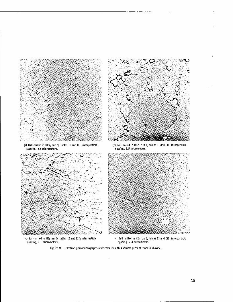
Microstructures and interparticle spacings. - Electron photomicrographs of the as- consolidated, chromium-thoria alloys listed in table IV are shown in figures 11(a) to (d). All these photomicrographs show dispersoid particles (Th02 with some Cr20„, see table IV) in the chromium matrix. The pits in some of these photomicrographs are pull
24
!<*£♦* f.
-
# as
■:^;
iatu '■
Ifllllföill
(a) Ball-milled in HC1; run 3, tables II and III; interparticle spacing, 3.5 micrometers.
(b) Ball-milled in HBr-, run 4, tables II and III; interparticle spacing, 6.5 micrometers.
"a?«si8
>*r-
-^*> rr--^f''
. V
-.-i'
-> -r ~ > -'" * "S V"
'S-
'.\~«,-V T ..r :>-^
#> (c) Ball-milled in HI; run 5, tables II and III; interparticle
spacing, 2.1 micrometers.
SB •N .'
WiMm §IüI
IH «mm ^
WI1111P wBmi
■'
"V: \
■ ■••. i'
A- 1 UNI > %
^"a ■ C-68-2552
(d) Ball-milled in HI; run 6, tables II and III; interparticle spacing, 2.4 micrometers.
Figure 11. - Electron photomicrographs of chromium with 4 volume percent thorium dioxide.
25
outs and not pores, as revealed by examination of unetched samples. Most of the dis- persoids segregated to the grain boundaries between elongated grains. Also the etchant appears to have attacked preferentially the chromium surrounding the particles. This ef- fect is particularly noticeable in figure 11(b).
The interparticle spacings (IPS) of the as-consolidated Cr-Th02 alloys listed in table IV were obtained by counting particles intercepted by straight lines in the photo- micrographs shown in figure 11. The IPS values so obtained are also listed in table IV. The material with the smallest IPS (2. 1 micrometers) was obtained by ball-milling in HI (milling run 5). The low IPS (as compared with those of the rest of the samples in table IV) may be a result of the fact that this material (sample 5) has the lowest calcu- lated amount (0. 10 volume percent) of Cr„0„ among the four as-hot-pressed samples. The second-best material obtained in this investigation has an IPS of 2. 4 micrometers and was also obtained by ball-milling in HI (run 6). Improved ball-milling techniques (longer times, different ball mix, etc.) and lower hydrogen reduction temperatures (as low as about 525° C) can be expected to further decrease the IPS of these Cr-ThO« al- loys. Lower hot-pressing temperature and/or shorter time at temperature can also be expected to decrease the IPS, other things being equal.
s\ 1 urn
<••>
'V
"I
Js >
,\ "A
.-•v
-I
i um
■^
A~^ C-68-2551
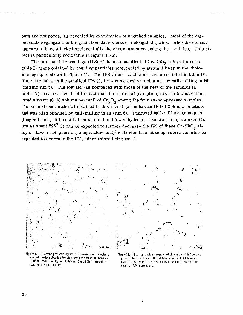
Figure 12. - Electron photomicrograph of chromium with 4 volume percent thorium dioxide after stabilizing anneal of 100 hours at 1318° C. Milled in HI; run 5, tables II and III; interparticle spacing, 5.2 micrometers.
F o
*, . '~~^
V
x a
/^\ ,>,
j *"> r
*i,sw>*"l
1#*~. C-68-2550
Figure 13. - Electron photomicrograph of chromium with 4 volume percent thorium dioxide after stabilizing anneal of 1 hour at 1450° C. Milled in HI; run 5, tables II and III; interparticle spacing, 6.5 micrometers.
26

Stability Anneals
Only the 2.1-micrometer-IPS, as-consolidated material (run 5, table IV) was tested for thermal stability. The electron photomicrograph of a specimen of this material an- nealed for 100 hours at 1318° C is shown in figure 12. The electron photomicrograph of another specimen of the same material annealed for 1 hour at 1450° C is shown in fig- ure 13. Both photomicrographs show the dispersoid (originally ThO« with small amounts of CrgOg, see table IV) imbedded in the chromium matrix and pits resulting from pull outs. Most of the agglomerated dispersoids are now located at triple points, and the originally elongated chromium grains (see fig. 11(c)) became equiaxed and grew in size. These microstructures are similar to those of similarly annealed, dispersion strength- ened chromium-molybdenum alloys reported in the literature (ref. 9).
The IPS of the specimen annealed for 100 hours at 1318° C is 5. 2 micrometers, and that of the sample annealed for 1 hour at 1450° C is 6. 5 micrometers.
Advantages of Hydrogen Iodide Ball-Milled Material
The material obtained by ball-milling in HI and cleaned at low temperature (610° C) is superior to the rest of the materials listed in table IV. This is evident from the parti- cle size and halogen pickup data in table II, the chemical analyses for residual halogen in' table in, the chemical analyses for ThO„ and oxygen in table IV, and most of all from comparison of IPS (table IV and figs. 11 to 13). From the safety standpoint, the fact that the iodides are the least reactive of the halides and that (liquid) hydrogen iodide is bottled under relatively low pressure (6. 45 atm gage or 6. 55x10 N/m gage) renders the process of milling in HI more attractive than milling in other hydrogen halides.
CONCLUDING REMARKS
Some results from this investigation are considered to be of general applicability. The results show that it was possible to comminute chromium and nickel to very fine par- ticle sizes by ball-milling in reactive hydrogen halide gases. On grinding, the metals reacted with the gaseous milling media and large percentages were converted to the cor- responding metal halides. The process is similar to that described in a previous inves- tigation by the author (ref. 6) in which it was postulated that comminution of most ductile metal and alloy powders to fine sizes requires their reacting with the grinding media. Similar results may also be obtainable by using the pure halogens or halogens diluted in nonreactive liquids as grinding media.
27
Since this investigation was intended to prove feasibility, no attempt was made to optimize the various processing steps towards obtaining alloys with still smaller IPS. Quite probably this IPS can be decreased (with constant amount of dispersoid) by
(1) Lowering the reduction temperature (2) Decreasing the particle size of the ball-milled powders (longer milling time,
different ball mix, etc.) (3) Using higher-purity raw materials and milling media (4) Hot-pressing at lower temperatures and/or for shorter time at temperature The feasibility of reducing nickel and chromium chlorides to the corresponding
metals containing low residual chlorine was also demonstrated. From this it is sur- mised that it may be possible to produce dispersion strengthened nickel and chromium (or their alloys) by ball-milling their halides and the dispersoid, followed by hydrogen re- duction of the halide in the resulting powder mixture. Most of these halides, however, are hygroscopic and for this reason special processing techniques would be required for their preparation and handling to prevent their contamination with (atmospheric) water.
SUMMARY OF RESULTS
The main purpose of the present investigation was to determine the feasibility of pro- ducing chromium with finely divided thorium dioxide, suitable for dispersion strength- ening, by ball-milling in hydrogen halide gases. In addition, the feasibility of producing fine nickel powder by ball-milling in hydrogen bromide and of reducing chromium and nickel chlorides in hydrogen was investigated. The results obtained can be summarized as follows:
1. Sub micron-size powders ranging in size from 0. 04 to 0. 09 micrometer were pro- duced by ball-milling chromium and chromium - thorium dioxide (Cr-ThO«) powders in hydrogen halides. From 11 to 18. 9 percent of the chromium was converted to the halide in the grinding process.
2. Nickel was comminuted to the finest-particle-size powder (0.023 micrometer) ob- tained in this investigation, by ball-milling in hydrogen bromide. In the grinding process, 26. 5 weight percent nickel was converted to nickel bromide (NiBr2).
3. The ground Cr-Th02, chromium, and nickel powders containing large percentages of halides resulting from the reaction with the milling media were subjected to reduction treatments in high-purity hydrogen under pulsating pressure. The resulting, cleaned Cr-ThOg powders ground initially in hydrogen iodide contained 6 ppm, or less, iodine, less than 50 ppm chlorine, and 500 ppm bromine, respectively. The cleaned chromium and nickel powders contained less than 200 ppm chlorine and 2300 ppm bromine, respec- tively. During this reducing treatment some agglomeration of the metal powders occur-
28
red, as shown by the fact that the 0.04-micrometer, as-milled chromium grew to 0. 53 micrometer during the treatment.
4. Despite the agglomeration and increase in size of the powders during the reducing treatments, an interparticle spacing (IPS) of 2. 1 micrometers was obtained in a Cr-ThO« alloy after isostatic hot-pressing of one of the cleaned powders. This powder had been obtained by ball-milling in hydrogen iodide. The other Cr-ThO« materials had IPS in the range of 2. 4 to 6. 5 micrometers.
5. The IPS of the 2. 1-micrometer, Cr-ThO, alloy increased to 5. 2 and 6. 5 microm- eters after stabilizing anneals of 100 hours at 1318° C and 1 hour at 1450° C, respective- ly. The reason for this instability is not known.
6. Clean, 0. 78-micrometer chromium and 0. 35-micrometer nickel powders con- taining 270 ppm, or less, chlorine were also obtained by reducing chromic chloride (CrClo) and nickel chloride (NiCU) powders in pulsating hydrogen at 675° and 358 C, respectively.
Lewis Research Center, National Aeronautics and Space Administration,
Cleveland, Ohio, July 18, 1968, 129-03-01-05-22.
REFERENCES
1. Cremens, Walter S.: Use of Submicron Metal and Nonmetal Powders for Dispersion Strengthened Alloys. Ultrafine Particles. William E. Kuhn, ed., John Wiley & Sons, Inc., 1963, pp. 457-478.
2. Cochardt, A. W.: Some Estimates of the Thermal Stability of Dispersion-Hardened Alloys. J. Metals, vol. 9, 1957, pp. 434-437.
3. Bunshah, R. F.; and Goetzel, C. G.: A Survey of Dispersion Strengthening of Metals and Alloys. New York Univ. (WADD TR 59-414), Mar. 1960.
4. Arias, Alan: Investigation of Thermal Shock Resistance of Zirconia with Metal Ad- ditions. NASA TN D-2464, 1964.
5. Weeton, JohnW.; and Quatinetz, Max: Cleaning and Stabilization of Dispersion Strengthened Materials. Presented at the AIME Conference on Oxide Dispersion Strengthening, Bolton Landing, N. Y., June 27-29, 1966.
6. Arias, Alan: The Role of Chemical Reactions in the Mechanism of Comminution of Ductile Metals into Ultrafine Powders by Grinding. NASA TN D-4862, 1968.
29
7. Googin, John M.: Sintering Tungsten Powder to High Density. Patent No. 3, 109, 735, United States, Nov. 5, 1963.
8. Orr, Clyde, Jr.; and Dallavalle, J. M.: Fine Particle Measurement. The MacMillan Co. , 1959, ch. 7.
9. Allen, R. E.: Dispersion-Strengthened Chromium Alloys. Rep. 66FPD284, General Electric Co. (NASA CR-85907), Oct. 20, 1966.
10. Hodgman, Charles D.; Weast, Robert C.; and Selby, Samuel M., eds.: Handbook of Chemistry and Physics. 41st ed., Chemical Rubber Publ. Co., 1959.
11. Kubaschewski, O.; and Evans, E. LL.: Metallurgical Thermochemistry. Third ed.,
Pergamon Press, 1958.
12. Wicks, C. E.; and Block, F. E.: Thermodynamic Properties of 65 Elements -
Their Oxides, Halides, Carbides, and Nitrides. Bulletin No. 605, U.S. Bureau of Mines, 1963.
13. Schneider, Kurt: Metallic Chromium from Chromium Chloride. Patent No. 2,246, 386, United States, June 17, 1941.
14. Campbell, Ivor E.; and Oxley, Joseph H.: Reducing Chromium Chloride to Metal with Hydrogen in a Fluidized Bed. Patent No. 3,043, 679, United States, July 10, 1962.
30

TABLE I. - CHARACTERIZATION OF RAW MATERIALS
Material3, Form Grade Purity,
percent
Manufacturer's specifications or
chemical analyses
Cr Electrolytic flake,
hammer-milled to
-30 mesh (5 (jm
average size)
High purity 99. 5 (min.) Oxygen, 104 ppmb; C, 97 ppmb; N, 85 ppmb;
Fe, 0. 33 wt. %
Ni Powder, 1. 2 fj.m (c) 99.7d Oxygen, 0.14 wt. % C, 0. 14 wt. %; Fe, 0.008wt. %
CrClg Powder High purity 99. 5d (c)
NiCl2 Powder Technical (c) (c)
Th02 Colloidal powder,
0.0050 to
0.0150 (im
High purity 99.9 (min.) S, 100 ppm; Ca, 350 ppm (max.); Fe, 10 ppm (max.); Si, 60 ppm (max.); Na, 100 ppm (max.);
all other elements < 50 ppm total
HC1 Under pressure in steel tanks
Technical 99.0 (min.) HC1 (liquid phase), 99. 5 wt. % (min.); hydro- carbons, 0. 5 wt. % (max.); water, 0. Olwt. %
(max.); C02, 0.Olwt. % (max.); inert mate-
rials, 0.1 wt. % (max.)
HBr Under pressure
in steel tanks (c) 99. 8 (min.) HBr, 99. 8 wt. % (min.); HC1, 0. 20 wt. % (max.)
HI Under pressure
in steel tanks (c) 98. 0 (min.) HI, minimum liquid purity of 96 percent (im-
purities consist of iodine in liquid phase and hy-
drogen in gas phase)
A Under pressure in steel tanks
High purity 99.9 (min.) 02 < 2 ppmb- CO, 200 ppmb; C02, 40 ppmb; H2, 300ppmb; H20, 4 ppmb; N2, 14 ppmb
b Name of manufacturer will be supplied upon request. 'Analysis from commercial laboratory.
^Unknown or not determined. Nominal analyses.
31
w Q
I Q W J
O CO W N i—i CO
w O
ft
CO W
S3
<
<
w K O
H
m 2
'S -a I. Ä O a, •H rt ra \ ü <3 «(N CD U Hö a a 3 5
CO 01
SP 3 1 11 - ~ a -a 5 1
to o > 3 m n- ö o
•a ■g a»
CO CD CD T5 co 5
"3 a S "8 -i a d 3 .a a a CD
43 <_>
cu a a0
CD to d J3 o u CD •a I ft
* a . a
O ft ft
Q to §
11 fs- 1 s l I ä O a o
o 10
3
6 43
•r-t to 0
•a I ft
a° - •S CD ^ a g 43
CD rt to
o
«
o 00 o
O CM CD
^. O) CO
-^ 00 t-
o CO
CO CN
o o u m
^ CO i-l
o o — o 00 3^f o>
in in *w
o X
o oo'
TH ci o> CM
o I— co c- in 1—1
^ i—c 1-1
o o n s < a a a
in
-r ffl
^* ^ ^ ^* OOCOCMCOCVICOWCOCSIO
O O *H 00 rH 00 rH 00 rH O0 O in in ^ TJ< TJ< ^ in
o o o o SnS-ijH,c:t<43S*43S-i43.r-< OOCJHUHOHCJH^;
■* in ■* •<i< ■* o 00 CM CO CO 00 •* CO •* CO CO CO CM
mu u
»-C CM CO
o Ü H
o CQ c -t-J
to •r-4 •1-4
CO CO
ä 3
a CD
IS ^ TS M
a a CD
to
CQ
5 ^a d
CO d .3 CD
c-i
CD § CO a d
O 3 CD
to u d
to Ä i—i
"8 ■a o
O
CO
3 CO
U
o d m «M
CD u TS a
d CO
>> f—i
CD
a to
s CQ
S co ..-1
d =3
w -a en
a a
CD
to d
CO
In CD
1 CD
'S d
CD C) T1 X!
o £ CJ d CM n «+H H i-( U, o CD
4-t o i-H
5 'S 1—1
CO
3 13 a
o a i
Ul
•a 42
O O
Of)
CD
c-c
o
o CM 3 a
o a o hn
CJ a d
■ (-* •e F
4-> CD >i
CD to d
to CD
d 3 ü
•i-i 10 a CD
o a 3 d u cK T3
CO 3 CO o ^ O 'T-* . +J hf)
CD a 1 !? o. o
1 'S O CO CD 1 CD
U
CD
o
to o CM
■a O O CO
d
CD
to
1
1—<
& a o
CN
O
J3
CO
CD to d to CD
CO
CO
a a TS
T3
s a d
a CD
u u CD ft
CD
2 CQ u O
M1
II
? a.
o a TJ X! c- CD CD
a CD
CM*
4-C O
a a
CD
CM" l-H
•1-4 CD
1
'S CD
s O o
U SH
O CD
U CD
is
.a CO
CD
Ü
£
ft CD
> U
CD
CO
o
'S CO
42
T3
CD
3 CO
CO
3 CD
a s CD
a CD CJ FH CD ft
4-» XS to
CO
a o ■a 13
ft
ä o
CD
13
*M O
CD
o
öi CD
to h
U
O o
a
CD
to d o CO
3 a
CD
M ft a o m
'S +J d
■3 ü
3
f O u fH o
«t-C
•a CD
a 3 CO
1 N
►. u
ä a
S 3 •a Q- a 3 U CD CD S>
XI CD a a FH CD
-M CD
TS
O CD
43
•8
■3 ■a
m d O
Q
CD co ■« CD TS
-M
CD
+*
g w
32
@
'llu
how
ro
gr
ress
m
en
cd Ä U •O ' • '
gure
s
tom
ic
hot-
p sp
eci
TH TH T-t T-H l ■ i i TH TH T-H r-t I ■ i
e a « a
CD
co in ."(DC ^
CD CD CD CD s* .3 a ;—- o O
ft O CD
3 ä g^ o i-< 05
8 ti SNÖ
a =i cd a
CD CD CD CD CD
T-l O >H
CO IB
Ö? LO 00 IM 1 CD CO LO I 03 O 'o !
£~ O ' T-H I o T-H * i
£3 in CM OJ O CO CO 00 c-
fcl +J CO ■* o> o> T-H CD O
CD
o £ o T-H i-t T-H O
CD
a CU CD CD CD CD CD
In tu h fe h h
09
H
CD 01
.—1
■a
CD Ö o) a
5 a
Ü o P CM 2
V
^~. o o o in LO
V „ CO ■*
O o CO CM
O O O C- CM CM
a 1—1
Ü 1—1
O m r-T h-T o O O
a d CD
Ä to a
g
-tf o o o ^—^ OS ^^ o CD 1< CD
U <M CM t-C TH CM "— TH *
« 5 a O o o o o O CO o
in CO ■*
CO CO CO CO CO "tf TH T-H
tj
g~es in o o T-H ■* OS
m CM t- t-
bD . ■^ ^ •* CM 00 CO >= -fc> o m in M< o ■* o
8 * o XJ T3 T3 ■o
in ■* ^ CM "tf CO t-
■H CD 01 3 tl « i O « 1) g P- H CD o,
CO 00 00 o t- CO CM <N ■*
CO •* -^ CO LO
03 a in o
■r-l a 5 CO r- Ir- o rH CO o
o
CO CO CO in m CO CO T-H TH
o cd
bD a CD CD rl CO CD LO o CO o LO co CT> in TH CO
is I 5° CD
CD CD t- CO CO CO
l-H H
a o 3 ?
a S 3 2
CO J>
i-H a SH & (-1 <+H M CfH ^ 'a bD c bp CM bD CM
■a a CM O .id o •H o .3 O •3 f3 t—
CD o 4-f 1^ 1 s a • a ■ a ,'
S O •a *n a "-1 d _S° N
2"ü h SH
a o o Ü u o ä O K
bD C
3 2 <M CO ■* in CO t- CO OS
t—1 u
bD
3
.a (H bD CD J5
!* LO
CQ Q.
CD CO
OD Z> a ^ O
3 ii O ■J-»
a a h ■ a.
nt > ■" ^ 3 bp B 8" U -H Ul a o •I-4
•O £ bD
CD ra bD CH cd ri
■Ö CM a cd ^ TI
CO J> ri
•= S ri r? *
■° Cd -w a bD
CO o< O CD O
-M a a ■d O 0D g
;^- *CD efH
fe T3
CN
O J3 H
? a ■a CD
~y <t>
CD CD
"cd ^
CD T3 CD
a CD
5 -a 1o m
13 CD
4-»
CD
a 3
a 1
CD CD CD CD
> S o CD CD
3 t T3 JH ■ö
3 +J cd cd C) o O
> PM 55 fe 55 cd X! Ü T3 CD
33
EH
8
< u H < EH w O
Pn O CO Ü S u < oo w o I—I
EH
« ft « W EH
oo W
<
<! U
ffl EH
Fig
ure s
how
ing
elec
tron p
hoto
-
mic
rog
rap
h
Cti ST "o" T? H TH T—I CSI CO TH
ted
, on
ass
um
p-
LS ta
ble
.
1 #1
CD
CD
OX! __
Y to 3 .S S
CD a
TJ< CO O in in r-t CM in TJI
CO CD CM in CD CM
if rt ni o j3 CD 'S B ^ 3 CO
1 t X a
X!
CM
CO a o
+-»
T5 c —x O CD o « to j-c C .3
•r-l
CD
g
CD"
s s-, XI
.-, ^ ^ O "-I ,-v ^o, o o o o
CO 2
Cd rt
^ 1—1
^ U
O
n o T-H X Ir- in
i cd s* CD
1 CD
EH
So ^-- *-. —. °° ° ^ 3 3 3 £ " 3
H TH
i! CD
.2 O XI SH 4-> <+-<
Ö •■"> CO
CO O CD <M CO Si >, o « to
O CD O
<* CO
73
CO
o CM
Ü
CO CO o O O PO C- CM T-H t-H l-t CO
o
B -M
CM
O XI H
t- m co co oo o m [- CO CO CO CO
CO CO CO CO CO CO
ven
by c
hem
ical a
n
ThO
„ w
as t
ied u
p a
r in
terc
ept
met
hod.
■s et)
o 0 CO
o T-H
to a o
Th
02 l
ost
on c
lean
ing
(b
ased
on
5.4
8w
t.
%
73 &- CD
H T}< ^ T^ CD •^ N t- t- t- CD
O CD N M CSI O) T-H
CO •r-t
CO >>
■a Ö ctt
.—1
dt o a CD XI O
4-»
CM
o XI H
T-i -^ co co co in OS TH CO CO CO CT5
TJ< in m in in TF
per
centa
ge
of T
hOg
calc
ula
ted f
rom
ThO
, gi
at o
xyge
n in e
xce
ss o
f th
at r
equ
ired
to
form
ted f
rom
ele
ctro
n p
ho
tom
icro
gra
ph
s by
lin
ea
eale
d.
73 C O o to e
• r* CO CO «>
C CD to >» O
CT> CD CO 00 CO ^ in t- in in in t- t— CD CD CD CD CD
O
a 1
73
-2 e o .2 rcj 4-> a d S c
o & O CO
1 CD CO 73
<
co TJI uo in in CD
o +J CO
■F-»
XI
■a •r-l fl CD
-M nS
s
Ö .g co "^ in in in CD
to
- g co ^ in in in CD
CD xi cd a
.—( O .-< 4-> O v-j oi O
34 NASA-I.ainiley, 1968 i7 E-4571

NATIONAL AERONAUTICS AND SPACE ADMINISTRATION
WASHINGTON, D.C. 20546
OFFICIAL BUSINESS FIRST CLASS MAIL
POSTAGE AND FEES PAID NATIONAL AERONAUTICS AND
SPACE ADMINISTRATION
ATS 6'^0^6 6o3lo "INSTITUTE
CENTER
011^ ü/,u 00 1 A2
)5 KI AVE 43201
CliLU^I'-US, CHin /VT-T-RUGEK J. «<U-^K
DACTMiCTno. If Undeliverabic (Section 158 WMMAS1LK. PostaiManu:ll) Do Not Return
"The aeronautical and space activities of the United States shall be conducted so as to contribute . . . to the expansion of human knoivl- edge of phenomena in the atmosphere and space. The Administration shall provide for the widest practicable and appropriate dissemination of information concerning its activities and the results thereof."
— NATIONAL AERONAUTICS AND SPACE ACT OF 1958
NASA SCIENTIFIC AND TECHNICAL PUBLICATIONS
TECHNICAL REPORTS: Scientific and technical information considered important, complete, and a lasting contribution to existing knowledge.
TECHNICAL NOTES: Information less broad in scope but nevertheless of importance as a contribution to existing knowledge.
TECHNICAL MEMORANDUMS: Information receiving limited distribution because of preliminary data, security classifica- tion, or other reasons.
CONTRACTOR REPORTS: Scientific and technical information generated under a NASA contract or grant and considered an important contribution to existing knowledge.
TECHNICAL TRANSLATIONS: Information published in a foreign language considered to merit NASA distribution in English.
SPECIAL PUBLICATIONS: Information derived from or of value to NASA activities. Publications include conference proceedings, monographs, data compilations, handbooks, sourcebooks, and special bibliographies.
TECHNOLOGY UTILIZATION PUBLICATIONS: Information on technology used by NASA that may be of particular interest in commercial and other non-aerospace applications. Publications include Tech Briefs, Technology Utilization Reports and Notes, and Technology Surveys.
Details on the availability of these publications may be obtained from:
SCIENTIFIC AND TECHNICAL INFORMATION DIVISION
NATIONAL AERONAUTICS AND SPACE ADMINISTRATION Washington, D.C. 20546