Embed Size (px)
Citation preview
EXPERIENCE WITH DEBOTTLENECKING OF
GAS DEHYDRATION PLANTS
Presented at the
56th
Laurance Reid Gas Conditioning Conference
Norman, Oklahoma
February 26 – March 1, 2006
Dr. Hugo Polderman
Shell Global Solutions International B.V.
P.O. Box 38000
1030 BN Amsterdam, The Netherlands
+31 20 630 2518
Gert Konijn
Shell Global Solutions International B.V.
P.O. Box 38000
1030 BN Amsterdam, The Netherlands
+31 20 630 3013
Dr. Hans Nooijen
Shell Global Solutions International B.V.
P.O. Box 38000
1030 BN Amsterdam, The Netherlands
+31 20 630 2301
Daniel Egger
Sulzer Chemtech Ltd
P.O. Box 65
CH-8404 Winterthur, Switzerland
+41 52 262 5008
ABSTRACT
Gas dehydration plants consist in essence of an inlet scrubber, a contactor and an outlet scrubber,
either in separate vessels or integrated in one vessel.
In most modern gas plants the contactor is a packed bed filled with conventional structured
packing. Often the performance of these plants is compromised by an inadequate inlet scrubber.
Condensate carried over into the contactor accumulates in the glycol regeneration system, eventually
limiting the gas handling capacity of the entire installation. Several case studies will be presented
showing how the capacity of such plants could be restored by upgrading of the inlet scrubber. Vane
packs which are less suitable for the operating conditions of a gas plant were replaced by Shell SMS
swirltube separators. The efficiency of swirltube separators was eventually further improved by the
application of high performance coalescing mistmats.
In cases where the contactor itself is the limiting factor, the throughput can be increased by 20-
30% by retrofitting high capacity structured packing. Conventional structured packing has a high de-
entrainment capacity of itself and it is usually operated at gas loads where the outlet scubber can be a
simple wire mesh demister. High capacity packing, is operated at a higher gas load and is more prone to
glycol carry over. In that case the outlet scrubber becomes critical. Good results were obtained in the
field with an SM swirltube demister.
Even further debottlenecking, up to 60-70% above the capacity of conventional packing, can be
obtained by retrofitting the contactor with contacting swirltubes. Here the contacting is performed by
dispersing glycol in the inlet of gas liquid cyclones. To achieve the very high glycol recovery rate
required, a high performance outlet scrubber is essential. Applications so far, amongst others in the Gulf
of Mexico, showed excellent gas drying performance. The glycol carryover was a factor 2-3 higher than
anticipated which could be traced again to inadequate inlet separation: condensate slip through the
contactor reduced the efficiency of the swirltube demister at the outlet.
EXPERIENCE WITH DEBOTTLENECKING OF
GAS DEHYDRATION PLANTS
Dr. Hugo Polderman, Shell Global Solutions International B.V., Amsterdam
Gert Konijn, Shell Global Solutions International B.V., Amsterdam
Dr. Hans Nooijen, Shell Global Solutions International B.V., Amsterdam
Daniel Egger, Sulzer Chemtech Ltd., Winterthur
Introduction
Gas dehydration plants consist in essence of an inlet scrubber, a contactor and an outlet scrubber.
Advanced separation and contacting swirltube technology provides all that is necessary to maximize the
gas handling capacity of each of these process steps.
The first chapter of this paper discusses the upgrading of inlet scrubbers. The second chapter
deals with the debottlenecking of the contactor itself and inherently the outlet demister.
1. Upgrading Of Inlet Scrubbers
In most modern gas plants the contactor is a packed bed filled with conventional structured
packing. Often the performance of these plants is compromised by an inadequate inlet scrubber.
Condensate carried over into the contactor accumulates in the glycol regeneration system, eventually
limiting the gas handling capacity of the entire installation.
In this section it will be shown how the capacity of such plants could be restored by upgrading of
the inlet separator. We will first explore the specifics of the various different demisters used in this
service.
1.1. Characteristics of the Most Common Scrubber Alternatives.
The gas/liquid separators commonly used as inlet scrubbers are wire mesh demisters, vane packs
and cyclone separators. The operating window of these devices for typical gas plant conditions is
compared in Fig. 1.1, which shows the variation of the achievable efficiency as a function of the gas
load. Filter coalescers form a separate category. This will be dealt with at the end of this section.
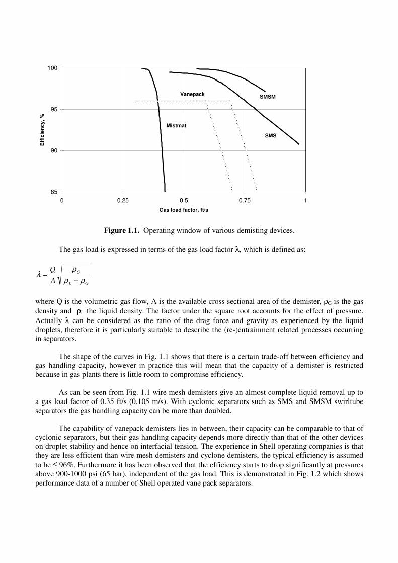
Figure 1.1. Operating window of various demisting devices.
The gas load is expressed in terms of the gas load factor λ, which is defined as:
GL
G
A
Q
ρρ
ρλ
−=
where Q is the volumetric gas flow, A is the available cross sectional area of the demister, ρG is the gas
density and ρL the liquid density. The factor under the square root accounts for the effect of pressure.
Actually λ can be considered as the ratio of the drag force and gravity as experienced by the liquid
droplets, therefore it is particularly suitable to describe the (re-)entrainment related processes occurring
in separators.
The shape of the curves in Fig. 1.1 shows that there is a certain trade-off between efficiency and
gas handling capacity, however in practice this will mean that the capacity of a demister is restricted
because in gas plants there is little room to compromise efficiency.
As can be seen from Fig. 1.1 wire mesh demisters give an almost complete liquid removal up to
a gas load factor of 0.35 ft/s (0.105 m/s). With cyclonic separators such as SMS and SMSM swirltube
separators the gas handling capacity can be more than doubled.
The capability of vanepack demisters lies in between, their capacity can be comparable to that of
cyclonic separators, but their gas handling capacity depends more directly than that of the other devices
on droplet stability and hence on interfacial tension. The experience in Shell operating companies is that
they are less efficient than wire mesh demisters and cyclone demisters, the typical efficiency is assumed
to be ≤ 96%. Furthermore it has been observed that the efficiency starts to drop significantly at pressures
above 900-1000 psi (65 bar), independent of the gas load. This is demonstrated in Fig. 1.2 which shows
performance data of a number of Shell operated vane pack separators.
85
90
95
100
0 0.25 0.5 0.75 1
Gas load factor, ft/s
Eff
icie
ncy, %
Mistmat
SMS
SMSMVanepack
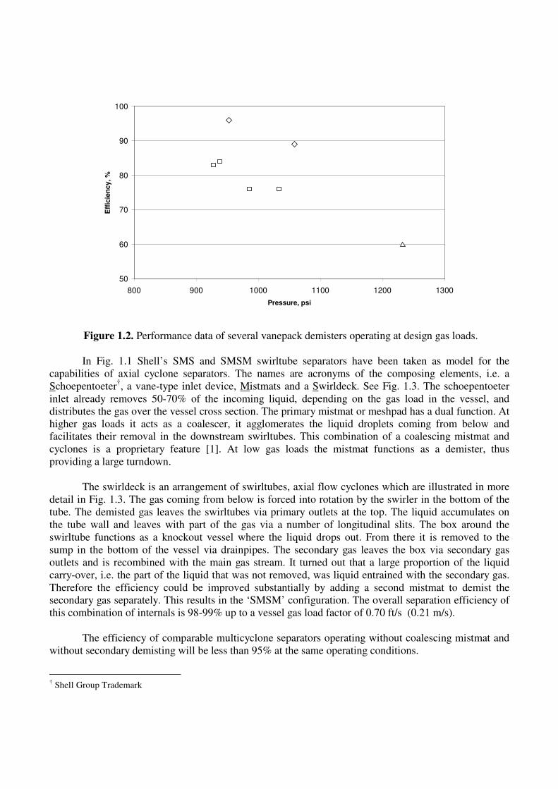
Figure 1.2. Performance data of several vanepack demisters operating at design gas loads.
In Fig. 1.1 Shell’s SMS and SMSM swirltube separators have been taken as model for the
capabilities of axial cyclone separators. The names are acronyms of the composing elements, i.e. a
Schoepentoeter†, a vane-type inlet device, Mistmats and a Swirldeck. See Fig. 1.3. The schoepentoeter
inlet already removes 50-70% of the incoming liquid, depending on the gas load in the vessel, and
distributes the gas over the vessel cross section. The primary mistmat or meshpad has a dual function. At
higher gas loads it acts as a coalescer, it agglomerates the liquid droplets coming from below and
facilitates their removal in the downstream swirltubes. This combination of a coalescing mistmat and
cyclones is a proprietary feature [1]. At low gas loads the mistmat functions as a demister, thus
providing a large turndown.
The swirldeck is an arrangement of swirltubes, axial flow cyclones which are illustrated in more
detail in Fig. 1.3. The gas coming from below is forced into rotation by the swirler in the bottom of the
tube. The demisted gas leaves the swirltubes via primary outlets at the top. The liquid accumulates on
the tube wall and leaves with part of the gas via a number of longitudinal slits. The box around the
swirltube functions as a knockout vessel where the liquid drops out. From there it is removed to the
sump in the bottom of the vessel via drainpipes. The secondary gas leaves the box via secondary gas
outlets and is recombined with the main gas stream. It turned out that a large proportion of the liquid
carry-over, i.e. the part of the liquid that was not removed, was liquid entrained with the secondary gas.
Therefore the efficiency could be improved substantially by adding a second mistmat to demist the
secondary gas separately. This results in the ‘SMSM’ configuration. The overall separation efficiency of
this combination of internals is 98-99% up to a vessel gas load factor of 0.70 ft/s (0.21 m/s).
The efficiency of comparable multicyclone separators operating without coalescing mistmat and
without secondary demisting will be less than 95% at the same operating conditions.
† Shell Group Trademark
50
60
70
80
90
100
800 900 1000 1100 1200 1300
Pressure, psi
Eff
icie
ncy, %
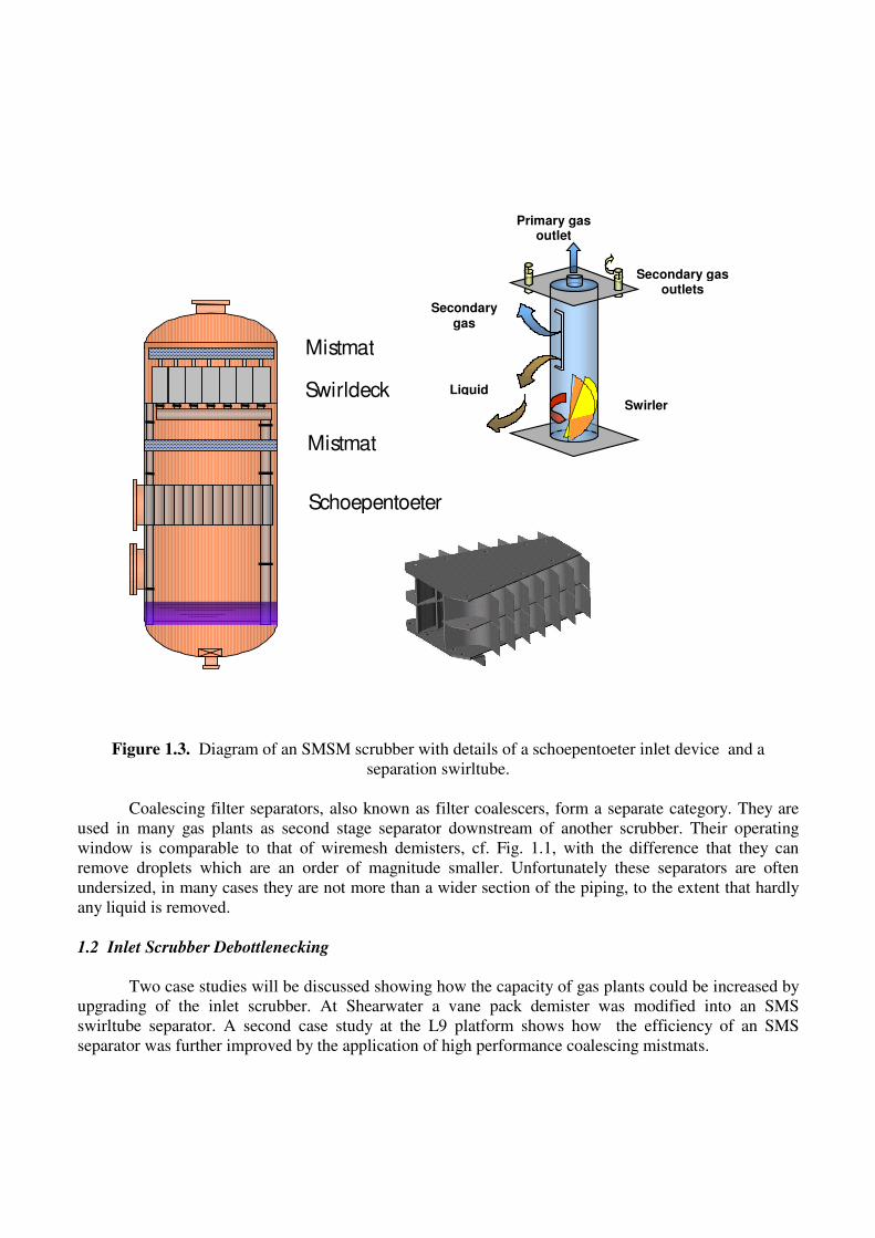
Figure 1.3. Diagram of an SMSM scrubber with details of a schoepentoeter inlet device and a
separation swirltube.
Coalescing filter separators, also known as filter coalescers, form a separate category. They are
used in many gas plants as second stage separator downstream of another scrubber. Their operating
window is comparable to that of wiremesh demisters, cf. Fig. 1.1, with the difference that they can
remove droplets which are an order of magnitude smaller. Unfortunately these separators are often
undersized, in many cases they are not more than a wider section of the piping, to the extent that hardly
any liquid is removed.
1.2 Inlet Scrubber Debottlenecking
Two case studies will be discussed showing how the capacity of gas plants could be increased by
upgrading of the inlet scrubber. At Shearwater a vane pack demister was modified into an SMS
swirltube separator. A second case study at the L9 platform shows how the efficiency of an SMS
separator was further improved by the application of high performance coalescing mistmats.
Mistmat
Schoepentoeter
Swirldeck
Mistmat
Primary gas outlet
Secondary gas outlets
Swirler
Secondary gas
Liquid
Shearwater Experience: from 310 to 410 MMscfd with Proper Inlet Separation
Shearwater is a gas production platform located in the North Sea, 150 miles east of Aberdeen. It
is operated by Shell but the original equipment design and selection was made by others. The gas from
Shearwater goes straight into the UK domestic gas grid, Therefore the plant is equipped with extensive
process facilities for acid gas removal and water and hydrocarbon dewpointing. The installation was
designed for 410 MMscfd (11.6 MMsm3/d), but the capacity appeared to be limited to about 75% of
design due to excessive condensate carry over into the glycol contactor and from there into the spent
glycol. The venting system of the glycol regenerator could not handle the accompanying extra vapour
load and bottlenecked the whole process.
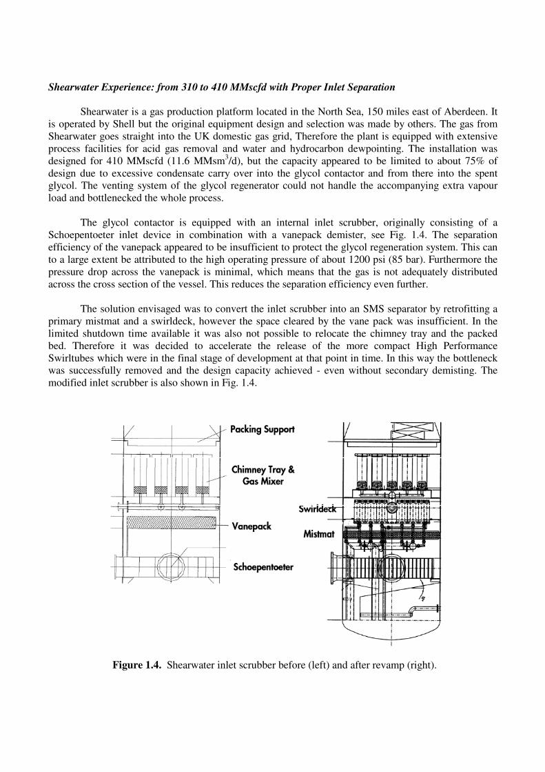
The glycol contactor is equipped with an internal inlet scrubber, originally consisting of a
Schoepentoeter inlet device in combination with a vanepack demister, see Fig. 1.4. The separation
efficiency of the vanepack appeared to be insufficient to protect the glycol regeneration system. This can
to a large extent be attributed to the high operating pressure of about 1200 psi (85 bar). Furthermore the
pressure drop across the vanepack is minimal, which means that the gas is not adequately distributed
across the cross section of the vessel. This reduces the separation efficiency even further.
The solution envisaged was to convert the inlet scrubber into an SMS separator by retrofitting a
primary mistmat and a swirldeck, however the space cleared by the vane pack was insufficient. In the
limited shutdown time available it was also not possible to relocate the chimney tray and the packed
bed. Therefore it was decided to accelerate the release of the more compact High Performance
Swirltubes which were in the final stage of development at that point in time. In this way the bottleneck
was successfully removed and the design capacity achieved - even without secondary demisting. The
modified inlet scrubber is also shown in Fig. 1.4.
Figure 1.4. Shearwater inlet scrubber before (left) and after revamp (right).
L9 Experience: Improved Separation of Difficult Fluid Mixtures
L9 is a Shell operated platform in the Dutch sector of the North Sea. The gas dehydration plant
of this platform was originally designed for 565 MMscfd (16 MMsm3/d) at an operating pressure of
1160 psi (80 bar). There appeared to be scope for increasing the production to 635 MMscfd (18.0
MMsm3/d), however, above 595 MMscfd (16.8 MMsm
3/d ) the plant was bottlenecked by excessive
foaming in the glycol flash drum and condensate/glycol separation problems in the slops system.
The inlet scrubber in this installation was a separate, external SMS separator upstream of the
contactor. Although this was still operating in its design window its efficiency was established to be 93-
96% rather than the expected 98%. Two things were unusual around this separator. In the first place the
liquid entering the vessel consisted of about equal quantities of water and hydrocarbon condensate, and
it was suspected that the relatively high proportion of water compromised the agglomeration efficiency
of the primary mistmat. Furthermore the drain pipes returning liquid accumulating on the support plate
of the swirldeck and the drain pipes from the swirldeck itself appeared to be connected to the same
header. Because these drains operate at different pressure levels this can very well lead to gas bypassing
and liquid reentrainment.
To improve the efficiency of this scrubber the functionality of the primary mistmat was split up
over two different mats with a different structure and composition: the lower one was optimised for the
separation and draining of water, the upper one for the coalescence of hydrocarbons. Furthermore a
secondary mistmat was added and the drain header was modified to separate the two drain systems.
With this SMMSM configuration L9 could be successfully ramped up to 630 MMscfd, the maximum
gas production of the reservoir.
A similar upgrade has recently been carried out at the Sean platform in the UK sector.
2. CONTACTOR DEBOTTLENECKING
In cases where the contactor itself is the limiting factor, the throughput can be increased by 20-
30% by retrofitting high capacity structured packing. If there is scope for even further debottlenecking
installation of Swirltube Trays can be considered. The operating window of the various contactor
options is compared in the Souders diagram of Fig. 2.1. The flow parameter is a measure for the liquid
to gas ratio and is defined as
L
G
G
L
M
M
ρ
ρϕ =
with ML and MG the liquid and gas mass flow rates. Glycol contactors will typically operate at the low
flow parameter side of the diagram.
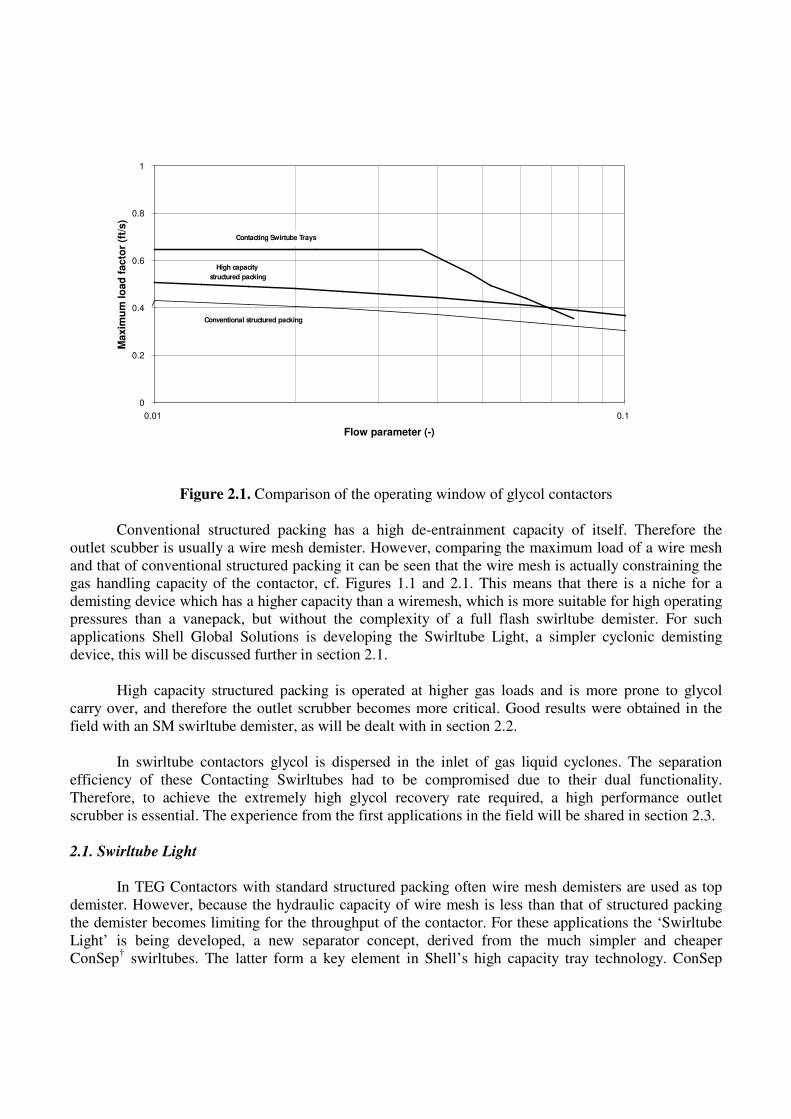
Figure 2.1. Comparison of the operating window of glycol contactors
Conventional structured packing has a high de-entrainment capacity of itself. Therefore the
outlet scubber is usually a wire mesh demister. However, comparing the maximum load of a wire mesh
and that of conventional structured packing it can be seen that the wire mesh is actually constraining the
gas handling capacity of the contactor, cf. Figures 1.1 and 2.1. This means that there is a niche for a
demisting device which has a higher capacity than a wiremesh, which is more suitable for high operating
pressures than a vanepack, but without the complexity of a full flash swirltube demister. For such
applications Shell Global Solutions is developing the Swirltube Light, a simpler cyclonic demisting
device, this will be discussed further in section 2.1.
High capacity structured packing is operated at higher gas loads and is more prone to glycol
carry over, and therefore the outlet scrubber becomes more critical. Good results were obtained in the
field with an SM swirltube demister, as will be dealt with in section 2.2.
In swirltube contactors glycol is dispersed in the inlet of gas liquid cyclones. The separation
efficiency of these Contacting Swirltubes had to be compromised due to their dual functionality.
Therefore, to achieve the extremely high glycol recovery rate required, a high performance outlet
scrubber is essential. The experience from the first applications in the field will be shared in section 2.3.
2.1. Swirltube Light
In TEG Contactors with standard structured packing often wire mesh demisters are used as top
demister. However, because the hydraulic capacity of wire mesh is less than that of structured packing
the demister becomes limiting for the throughput of the contactor. For these applications the ‘Swirltube
Light’ is being developed, a new separator concept, derived from the much simpler and cheaper
ConSep† swirltubes. The latter form a key element in Shell’s high capacity tray technology. ConSep
0
0.2
0.4
0.6
0.8
1
0.01 0.1
Flow parameter (-)
Maxim
um
lo
ad
facto
r (f
t/s)
High capacity
structured packing
Conventional structured packing
Contacting Swirtube Trays
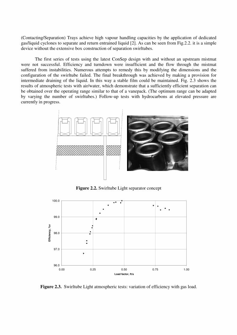
(Contacting/Separation) Trays achieve high vapour handling capacities by the application of dedicated
gas/liquid cyclones to separate and return entrained liquid [2]. As can be seen from Fig.2.2. it is a simple
device without the extensive box construction of separation swirltubes.
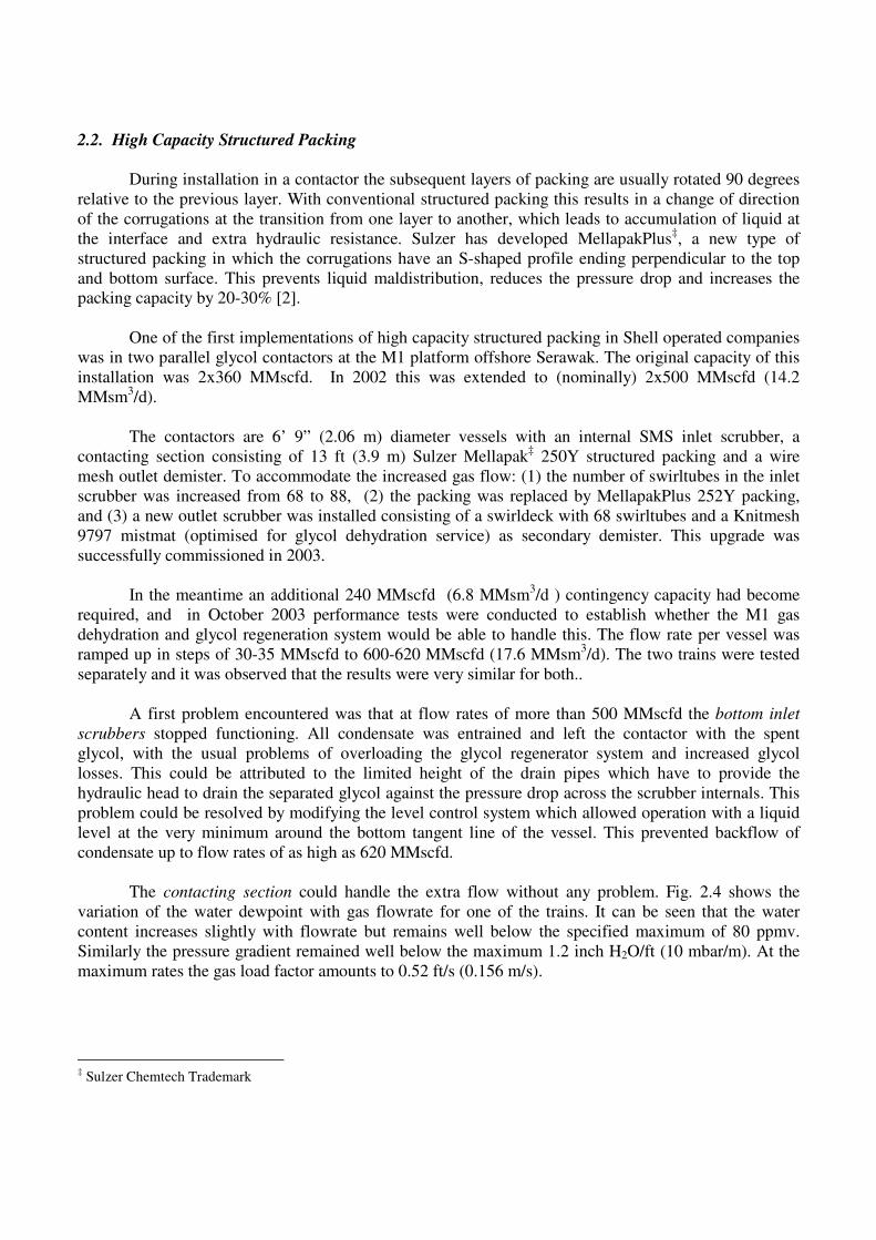
The first series of tests using the latest ConSep design with and without an upstream mistmat
were not successful. Efficiency and turndown were insufficient and the flow through the mistmat
suffered from instabilities. Numerous attempts to remedy this by modifying the dimensions and the
configuration of the swirltube failed. The final breakthrough was achieved by making a provision for
intermediate draining of the liquid. In this way a stable film could be maintained. Fig. 2.3 shows the
results of atmospheric tests with air/water, which demonstrate that a sufficiently efficient separation can
be obtained over the operating range similar to that of a vanepack. (The optimum range can be adapted
by varying the number of swirltubes.) Follow-up tests with hydrocarbons at elevated pressure are
currently in progress.
Figure 2.2. Swirltube Light separator concept
Figure 2.3. Swirltube Light atmospheric tests: variation of efficiency with gas load.
96.0
97.0
98.0
99.0
100.0
0.00 0.25 0.50 0.75 1.00
Load factor, ft/s
Eff
icie
nc
y,
%v
2.2. High Capacity Structured Packing
During installation in a contactor the subsequent layers of packing are usually rotated 90 degrees
relative to the previous layer. With conventional structured packing this results in a change of direction
of the corrugations at the transition from one layer to another, which leads to accumulation of liquid at
the interface and extra hydraulic resistance. Sulzer has developed MellapakPlus‡, a new type of
structured packing in which the corrugations have an S-shaped profile ending perpendicular to the top
and bottom surface. This prevents liquid maldistribution, reduces the pressure drop and increases the
packing capacity by 20-30% [2].
One of the first implementations of high capacity structured packing in Shell operated companies
was in two parallel glycol contactors at the M1 platform offshore Serawak. The original capacity of this
installation was 2x360 MMscfd. In 2002 this was extended to (nominally) 2x500 MMscfd (14.2
MMsm3/d).
The contactors are 6’ 9” (2.06 m) diameter vessels with an internal SMS inlet scrubber, a
contacting section consisting of 13 ft (3.9 m) Sulzer Mellapak‡ 250Y structured packing and a wire
mesh outlet demister. To accommodate the increased gas flow: (1) the number of swirltubes in the inlet
scrubber was increased from 68 to 88, (2) the packing was replaced by MellapakPlus 252Y packing,
and (3) a new outlet scrubber was installed consisting of a swirldeck with 68 swirltubes and a Knitmesh
9797 mistmat (optimised for glycol dehydration service) as secondary demister. This upgrade was
successfully commissioned in 2003.
In the meantime an additional 240 MMscfd (6.8 MMsm3/d ) contingency capacity had become
required, and in October 2003 performance tests were conducted to establish whether the M1 gas
dehydration and glycol regeneration system would be able to handle this. The flow rate per vessel was
ramped up in steps of 30-35 MMscfd to 600-620 MMscfd (17.6 MMsm3/d). The two trains were tested
separately and it was observed that the results were very similar for both..
A first problem encountered was that at flow rates of more than 500 MMscfd the bottom inlet
scrubbers stopped functioning. All condensate was entrained and left the contactor with the spent
glycol, with the usual problems of overloading the glycol regenerator system and increased glycol
losses. This could be attributed to the limited height of the drain pipes which have to provide the
hydraulic head to drain the separated glycol against the pressure drop across the scrubber internals. This
problem could be resolved by modifying the level control system which allowed operation with a liquid
level at the very minimum around the bottom tangent line of the vessel. This prevented backflow of
condensate up to flow rates of as high as 620 MMscfd.
The contacting section could handle the extra flow without any problem. Fig. 2.4 shows the
variation of the water dewpoint with gas flowrate for one of the trains. It can be seen that the water
content increases slightly with flowrate but remains well below the specified maximum of 80 ppmv.
Similarly the pressure gradient remained well below the maximum 1.2 inch H2O/ft (10 mbar/m). At the
maximum rates the gas load factor amounts to 0.52 ft/s (0.156 m/s).
‡ Sulzer Chemtech Trademark
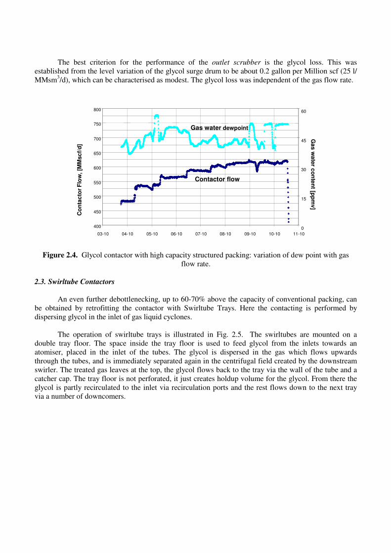
The best criterion for the performance of the outlet scrubber is the glycol loss. This was
established from the level variation of the glycol surge drum to be about 0.2 gallon per Million scf (25 l/
MMsm3/d), which can be characterised as modest. The glycol loss was independent of the gas flow rate.
Figure 2.4. Glycol contactor with high capacity structured packing: variation of dew point with gas
flow rate.
2.3. Swirltube Contactors
An even further debottlenecking, up to 60-70% above the capacity of conventional packing, can
be obtained by retrofitting the contactor with Swirltube Trays. Here the contacting is performed by
dispersing glycol in the inlet of gas liquid cyclones.
The operation of swirltube trays is illustrated in Fig. 2.5. The swirltubes are mounted on a
double tray floor. The space inside the tray floor is used to feed glycol from the inlets towards an
atomiser, placed in the inlet of the tubes. The glycol is dispersed in the gas which flows upwards
through the tubes, and is immediately separated again in the centrifugal field created by the downstream
swirler. The treated gas leaves at the top, the glycol flows back to the tray via the wall of the tube and a
catcher cap. The tray floor is not perforated, it just creates holdup volume for the glycol. From there the
glycol is partly recirculated to the inlet via recirculation ports and the rest flows down to the next tray
via a number of downcomers.
03-10 04-10 05-10 06-10 07-10 08-10 09-10 10-10 11-10
400
450
500
550
600
650
700
750
800
Co
nta
cto
r F
low
, [M
Msc
f/d
]
0
15
30
45
60
Ga
s w
ate
r co
nte
nt [p
pm
v]
Contactor flow
Gas water dewpoint
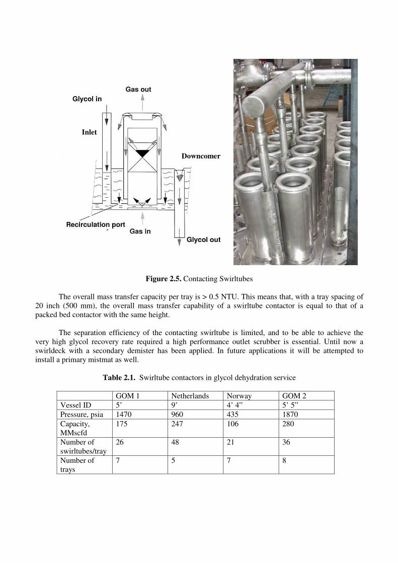
Figure 2.5. Contacting Swirltubes
The overall mass transfer capacity per tray is > 0.5 NTU. This means that, with a tray spacing of
20 inch (500 mm), the overall mass transfer capability of a swirltube contactor is equal to that of a
packed bed contactor with the same height.
The separation efficiency of the contacting swirltube is limited, and to be able to achieve the
very high glycol recovery rate required a high performance outlet scrubber is essential. Until now a
swirldeck with a secondary demister has been applied. In future applications it will be attempted to
install a primary mistmat as well.
Table 2.1. Swirltube contactors in glycol dehydration service
GOM 1 Netherlands Norway GOM 2
Vessel ID 5’ 9’ 4’ 4” 5’ 5”
Pressure, psia 1470 960 435 1870
Capacity,
MMscfd
175 247 106 280
Number of
swirltubes/tray
26 48 21 36
Number of
trays
7 5 7 8
Inlet
Downcomer
Over the past ten years four contactors have been retrofitted with contacting swirltubes. An
overview is given in Table 2.1. All these applications showed excellent gas drying performance,
however with exception of the contactor in the Netherlands the glycol carryover was a factor 2-3 higher
than anticipated. This could be traced again to inadequate inlet separation: condensate slip through the
contactor reduced the efficiency of the swirltube demister at the outlet. In all these cases the
debottlenecking of the inlet scrubbers was not in the scope of Shell Global Solutions.
The performance of one of the gas plants in the Gulf of Mexico (GOM 2 in the table) was
exemplary. The capacity of the relevant contactor was increased from 215 MMscfd to 280 MMscfd (6.1
to 7.9 MMsm3/d) by replacing the structured packing by swirl tube trays; a separation swirl tube deck
with secondary mistmat was installed as outlet scrubber. During the same shutdown, the upstream inlet
scrubber was retrofitted with third party internals to accommodate the higher gas throughput.
The contactor showed an excellent drying performance since start up with reported dew points of
1-2 lb/MMscf versus 5 lb/MMscf (80 mg/Sm3) as per design. However, on the basis of the glycol
depletion rates it could already be established that the glycol losses, though varying strongly from day to
day, were much higher than designed for.
In a dedicated test campaign the carry-over of liquid with the export gas was established by
isokinetic sampling. The glycol concentration appeared to be about 1 gallon/MMscf. However, the
condensate concentration was more than 6 gallon/MMscf, i.e. a multiple of the glycol concentration.
This is the main reason for the high glycol losses: the quantity of condensate passing through the outlet
scrubber is a multiple of the quantity of glycol, whereas the swirldeck was designed for glycol
separation, which requires less swirltubes.
The inlet scrubber was rather small, however, it would have been possible to achieve a better
performance with a Shell proprietary separation swirldeck with secondary demisting. This has a higher
liquid handling capacity and a higher separation efficiency at high liquid loads than the third-party
cyclone deck actually installed.
In future prospects application of Swirltube Trays will only be considered downstream of
properly designed SMSM separators.
References
1. ‘Column for removing liquid from a gas’, U.S. Patent 4767424
2. www.sulzerchemtech.com
Note The technical information contained in this presentation is controlled for export by the US
Government under EAR99. Please do not forward the contents without obtaining authorization from the
author.