Embed Size (px)
Citation preview
Debottlenecking the Retrofitted Thermally Coupled DistillationSequenceNguyen Van Duc Long and Moonyong Lee†
School of Chemical Engineering, Yeungnam University, Gyeongsan 712-749, South Korea
ABSTRACT: The thermally coupled distillation sequence (TCDS) has attracted increasing interest in a range of chemicalprocesses because of its potential energy and capital cost savings in multicomponent separations. In addition, the TCDS hasattracted particular attention in retrofit projects because of its lower energy requirements compared to the existing conventionalcolumn sequence, easy design, and small modification. This, however, can create a bottleneck in the column. The main aim ofthis study was to identify bottlenecks in a retrofitted TCDS systematically using a hydraulic performance indicator and fractionalutilization of area (FUA), and to propose a novel strategy for the use of a side reboiler or a side condenser for debottlenecking ofthe column. A practical method using the response surface methodology (RSM) is proposed for TCDS design and optimization.The optimum TCDS structure can be observed in a practical manner while minimizing the simulation runs. The use of a sidereboiler or a side condenser in a retrofitted TCDS could debottleneck the column and increase the process capacity. This canreduce the temperature difference between the top and side reboiler location, or between the bottom and side condenserlocation, which has potential use as a heat pump by utilizing the heat from the top vapor stream or side vapor stream,respectively. The column grand composite curve (CGCC) was used to indicate the thermodynamic feasibility of theimplementation of the heat pump system into the TCDS. The results showed that the operating cost could be reduceddramatically through novel combinations of internal and external heat integration, such as TCDS using a top vaporrecompression heat pump.
1. INTRODUCTIONIn recent years, there has been increasing incentive to improvethe efficiency of existing capital in chemical processing facilities.Retrofit design projects aim to identify ways of maximizing theuse of existing equipment and minimizing the expenditure onnew capital, when production objectives change. Examples ofnew objectives are increasing the throughput of a process,accommodating new feedstock, producing products with ahigher value, reducing operating costs, energy requirements, oratmospheric emissions, and incorporating new technologiesinto the process. At the end of the 1980s, 70−80% of capitalinvestment projects in the processing industry were retrofitprojects.1
Process integration is an interesting option for retrofit thathas been successful in reducing the energy requirementscompared to processes where all the units are configured withlittle or no integration.2,3 In particular, the use of columns withthermal coupling has attracted considerable interest in recentyears.4−19 Thermally coupled distillation sequences TCDSswere obtained through the implementation of interconnectingstreams (one in the vapor phase and the other in the liquidphase) between two columns. Each interconnection replacesone condenser or one reboiler from one of the columns,providing potential cost savings.Several studies have examined the application of dividing wall
columns in a retrofit.3,20−23 They reported that the dividingwall column can be used to save energy and cost. Nevertheless,there can be practical difficulties:20 In addition to existingcolumn constraints, such as a fixed column diameter, most ofthese concerns focused on the need to modify the columnshells to accommodate the dividing wall and have anothernozzle fitted to withdraw the middle product. Such
modifications to install a dividing wall, which might involvethe removal of tray support rings and the replacement ofexisting internals, can be a major undertaking. In addition, themechanical design aspects of the column, such as mechanicalstress, are affected by changing the feed or side-draw locations.When the columns use tray type internals for some reasons,
the internal type can retard the retrofit by a DWC configurationbecause packing type internals are preferred overwhelmingly ina dividing wall section. Furthermore, when retrofitting twocolumns to a DWC, the selected, existing column is modifiedby the addition of a middle section, which houses the dividingwall.22 This will be cut on-site into two portions to form the topand bottom sections of the retrofitted DWC. The middlesection of the retrofitted DWC is shop fabricated and would beavailable before actual on-site retrofitting begins. This sectionwas first welded to the top of the bottom section, and theremoved top portion was then welded to the top of the middlesection to complete the column. Therefore, although thedividing wall column might initially be the best option forretrofit projects, these concerns must be addressed fully duringa retrofit design. These modifications often require significantplant downtime, which leads to a loss of production and aninterruption of the product supply to the customers. On theother hand, DWC is not attractive when the plant lifetime isnot long because of the lengthy payback period. Instead, TCDShas attracted considerable attention in retrofit projects due to
Received: April 10, 2013Revised: August 5, 2013Accepted: August 6, 2013Published: August 6, 2013
Article
pubs.acs.org/IECR
© 2013 American Chemical Society 12635 dx.doi.org/10.1021/ie401140v | Ind. Eng. Chem. Res. 2013, 52, 12635−12645
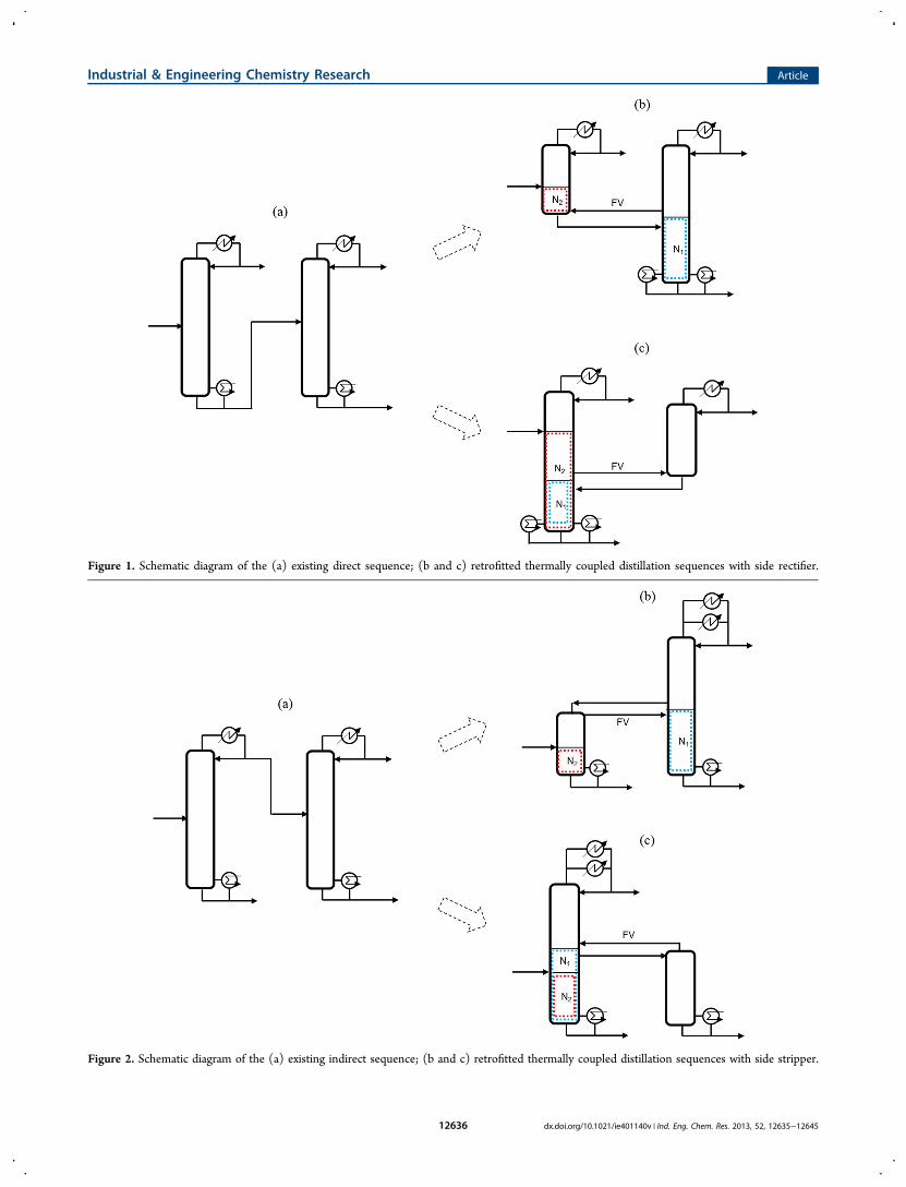
Figure 1. Schematic diagram of the (a) existing direct sequence; (b and c) retrofitted thermally coupled distillation sequences with side rectifier.
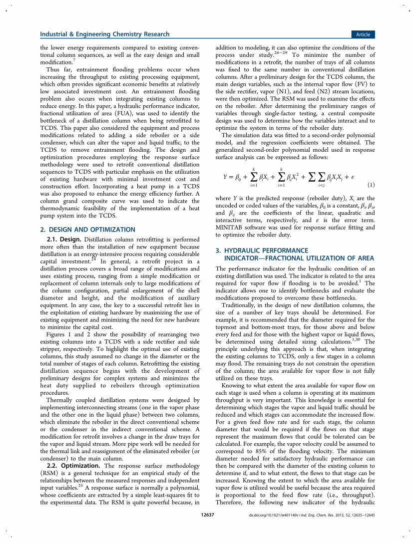
Figure 2. Schematic diagram of the (a) existing indirect sequence; (b and c) retrofitted thermally coupled distillation sequences with side stripper.
Industrial & Engineering Chemistry Research Article
dx.doi.org/10.1021/ie401140v | Ind. Eng. Chem. Res. 2013, 52, 12635−1264512636
the lower energy requirements compared to existing conven-tional column sequences, as well as the easy design and smallmodification.7
Thus far, entrainment flooding problems occur whenincreasing the throughput to existing processing equipment,which often provides significant economic benefits at relativelylow associated investment cost. An entrainment floodingproblem also occurs when integrating existing columns toreduce energy. In this paper, a hydraulic performance indicator,fractional utilization of area (FUA), was used to identify thebottleneck of a distillation column when being retrofitted toTCDS. This paper also considered the equipment and processmodifications related to adding a side reboiler or a sidecondenser, which can alter the vapor and liquid traffic, to theTCDS to remove entrainment flooding. The design andoptimization procedures employing the response surfacemethodology were used to retrofit conventional distillationsequences to TCDS with particular emphasis on the utilizationof existing hardware with minimal investment cost andconstruction effort. Incorporating a heat pump in a TCDSwas also proposed to enhance the energy efficiency further. Acolumn grand composite curve was used to indicate thethermodynamic feasibility of the implementation of a heatpump system into the TCDS.
2. DESIGN AND OPTIMIZATION2.1. Design. Distillation column retrofitting is performed
more often than the installation of new equipment becausedistillation is an energy-intensive process requiring considerablecapital investment.24 In general, a retrofit project in adistillation process covers a broad range of modifications anduses existing process, ranging from a simple modification orreplacement of column internals only to large modifications ofthe column configuration, partial enlargement of the shelldiameter and height, and the modification of auxiliaryequipment. In any case, the key to a successful retrofit lies inthe exploitation of existing hardware by maximizing the use ofexisting equipment and minimizing the need for new hardwareto minimize the capital cost.Figures 1 and 2 show the possibility of rearranging two
existing columns into a TCDS with a side rectifier and sidestripper, respectively. To highlight the optimal use of existingcolumns, this study assumed no change in the diameter or thetotal number of stages of each column. Retrofitting the existingdistillation sequence begins with the development ofpreliminary designs for complex systems and minimizes theheat duty supplied to reboilers through optimizationprocedures.Thermally coupled distillation systems were designed by
implementing interconnecting streams (one in the vapor phaseand the other one in the liquid phase) between two columns,which eliminate the reboiler in the direct conventional schemeor the condenser in the indirect conventional scheme. Amodification for retrofit involves a change in the draw trays forthe vapor and liquid stream. More pipe work will be needed forthe thermal link and reassignment of the eliminated reboiler (orcondenser) to the main column.2.2. Optimization. The response surface methodology
(RSM) is a general technique for an empirical study of therelationships between the measured responses and independentinput variables.25 A response surface is normally a polynomial,whose coefficients are extracted by a simple least-squares fit tothe experimental data. The RSM is quite powerful because, in
addition to modeling, it can also optimize the conditions of theprocess under study.26−29 To minimize the number ofmodifications in a retrofit, the number of trays of all columnswas fixed to the same number in conventional distillationcolumns. After a preliminary design for the TCDS column, themain design variables, such as the internal vapor flow (FV) tothe side rectifier, vapor (N1), and feed (N2) stream locations,were then optimized. The RSM was used to examine the effectson the reboiler. After determining the preliminary ranges ofvariables through single-factor testing, a central compositedesign was used to determine how the variables interact and tooptimize the system in terms of the reboiler duty.The simulation data was fitted to a second-order polynomial
model, and the regression coefficients were obtained. Thegeneralized second-order polynomial model used in responsesurface analysis can be expressed as follows:
∑ ∑ ∑ ∑β β β β ε= + + + += = <
Y X X X Xi
k
i ii
k
ii ii j
ij i j01 1
2
(1)
where Y is the predicted response (reboiler duty), Xi are theuncoded or coded values of the variables, β0 is a constant, βi, βii,and βij are the coefficients of the linear, quadratic andinteractive terms, respectively, and ε is the error term.MINITAB software was used for response surface fitting andto optimize the reboiler duty.
3. HYDRAULIC PERFORMANCEINDICATORFRACTIONAL UTILIZATION OF AREA
The performance indicator for the hydraulic condition of anexisting distillation was used. The indicator is related to the arearequired for vapor flow if flooding is to be avoided.1 Theindicator allows one to identify bottlenecks and evaluate themodifications proposed to overcome these bottlenecks.Traditionally, in the design of new distillation columns, the
size of a number of key trays should be determined. Forexample, it is recommended that the diameter required for thetopmost and bottom-most trays, for those above and belowevery feed and for those with the highest vapor or liquid flows,be determined using detailed sizing calculations.1,30 Theprinciple underlying this approach is that, when integratingthe existing columns to TCDS, only a few stages in a columnmay flood. The remaining trays do not constrain the operationof the column; the area available for vapor flow is not fullyutilized on these trays.Knowing to what extent the area available for vapor flow on
each stage is used when a column is operating at its maximumthroughput is very important. This knowledge is essential fordetermining which stages the vapor and liquid traffic should bereduced and which stages can accommodate the increased flow.For a given feed flow rate and for each stage, the columndiameter that would be required if the flows on that stagerepresent the maximum flows that could be tolerated can becalculated. For example, the vapor velocity could be assumed tocorrespond to 85% of the flooding velocity. The minimumdiameter needed for satisfactory hydraulic performance canthen be compared with the diameter of the existing column todetermine if, and to what extent, the flows to that stage can beincreased. Knowing the extent to which the area available forvapor flow is utilized would be useful because the area requiredis proportional to the feed flow rate (i.e., throughput).Therefore, the following new indicator of the hydraulic
Industrial & Engineering Chemistry Research Article
dx.doi.org/10.1021/ie401140v | Ind. Eng. Chem. Res. 2013, 52, 12635−1264512637
performance of an existing distillation column, the fractionalutilization of area (FUA), is proposed:
=FUAarea required on stage i for vapor flowarea available on stage i for vapor flow (2)
where the area required for vapor flow is calculated for a givenapproach to flooding conditions (e.g., when the vapor velocityis 85% of the flooding velocity). A more detailed descriptionabout the FUA can be found elsewhere.1
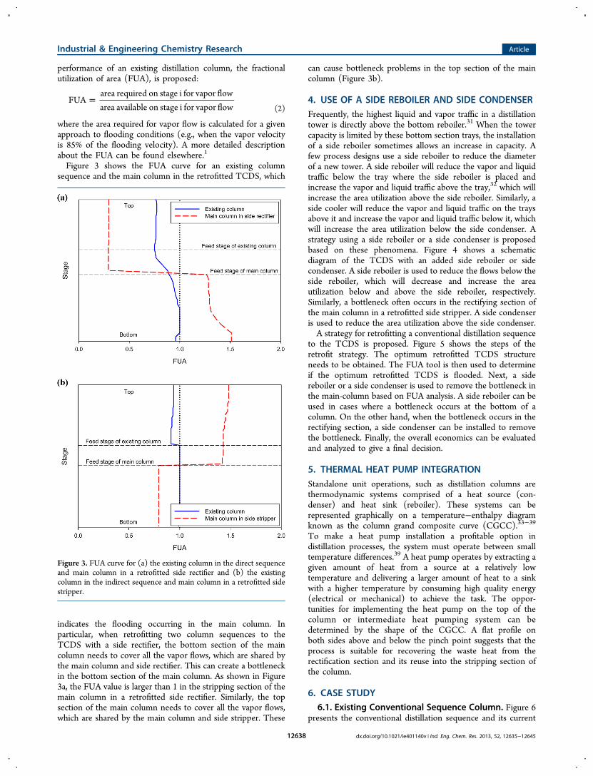
Figure 3 shows the FUA curve for an existing columnsequence and the main column in the retrofitted TCDS, which
indicates the flooding occurring in the main column. Inparticular, when retrofitting two column sequences to theTCDS with a side rectifier, the bottom section of the maincolumn needs to cover all the vapor flows, which are shared bythe main column and side rectifier. This can create a bottleneckin the bottom section of the main column. As shown in Figure3a, the FUA value is larger than 1 in the stripping section of themain column in a retrofitted side rectifier. Similarly, the topsection of the main column needs to cover all the vapor flows,which are shared by the main column and side stripper. These
can cause bottleneck problems in the top section of the maincolumn (Figure 3b).
4. USE OF A SIDE REBOILER AND SIDE CONDENSERFrequently, the highest liquid and vapor traffic in a distillationtower is directly above the bottom reboiler.31 When the towercapacity is limited by these bottom section trays, the installationof a side reboiler sometimes allows an increase in capacity. Afew process designs use a side reboiler to reduce the diameterof a new tower. A side reboiler will reduce the vapor and liquidtraffic below the tray where the side reboiler is placed andincrease the vapor and liquid traffic above the tray,32 which willincrease the area utilization above the side reboiler. Similarly, aside cooler will reduce the vapor and liquid traffic on the traysabove it and increase the vapor and liquid traffic below it, whichwill increase the area utilization below the side condenser. Astrategy using a side reboiler or a side condenser is proposedbased on these phenomena. Figure 4 shows a schematicdiagram of the TCDS with an added side reboiler or sidecondenser. A side reboiler is used to reduce the flows below theside reboiler, which will decrease and increase the areautilization below and above the side reboiler, respectively.Similarly, a bottleneck often occurs in the rectifying section ofthe main column in a retrofitted side stripper. A side condenseris used to reduce the area utilization above the side condenser.A strategy for retrofitting a conventional distillation sequence
to the TCDS is proposed. Figure 5 shows the steps of theretrofit strategy. The optimum retrofitted TCDS structureneeds to be obtained. The FUA tool is then used to determineif the optimum retrofitted TCDS is flooded. Next, a sidereboiler or a side condenser is used to remove the bottleneck inthe main-column based on FUA analysis. A side reboiler can beused in cases where a bottleneck occurs at the bottom of acolumn. On the other hand, when the bottleneck occurs in therectifying section, a side condenser can be installed to removethe bottleneck. Finally, the overall economics can be evaluatedand analyzed to give a final decision.
5. THERMAL HEAT PUMP INTEGRATIONStandalone unit operations, such as distillation columns arethermodynamic systems comprised of a heat source (con-denser) and heat sink (reboiler). These systems can berepresented graphically on a temperature−enthalpy diagramknown as the column grand composite curve (CGCC).33−39
To make a heat pump installation a profitable option indistillation processes, the system must operate between smalltemperature differences.39 A heat pump operates by extracting agiven amount of heat from a source at a relatively lowtemperature and delivering a larger amount of heat to a sinkwith a higher temperature by consuming high quality energy(electrical or mechanical) to achieve the task. The oppor-tunities for implementing the heat pump on the top of thecolumn or intermediate heat pumping system can bedetermined by the shape of the CGCC. A flat profile onboth sides above and below the pinch point suggests that theprocess is suitable for recovering the waste heat from therectification section and its reuse into the stripping section ofthe column.
6. CASE STUDY6.1. Existing Conventional Sequence Column. Figure 6
presents the conventional distillation sequence and its current
Figure 3. FUA curve for (a) the existing column in the direct sequenceand main column in a retrofitted side rectifier and (b) the existingcolumn in the indirect sequence and main column in a retrofitted sidestripper.
Industrial & Engineering Chemistry Research Article
dx.doi.org/10.1021/ie401140v | Ind. Eng. Chem. Res. 2013, 52, 12635−1264512638
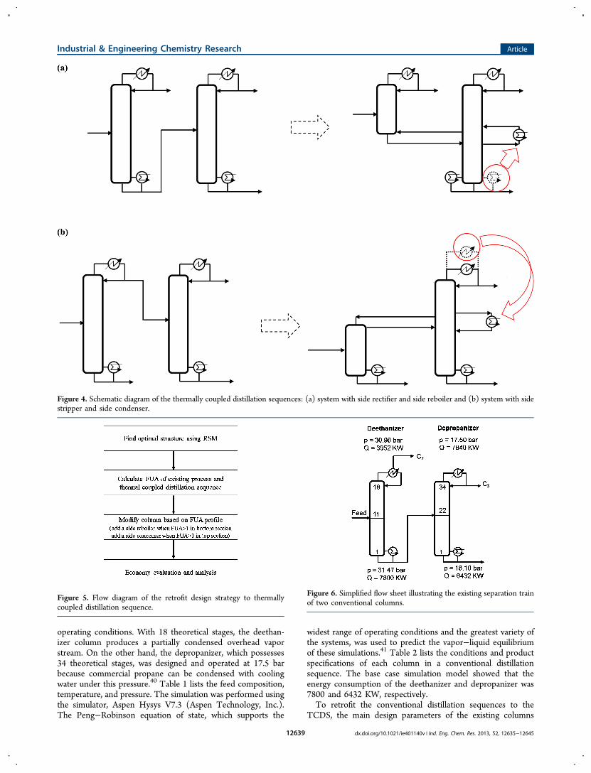
operating conditions. With 18 theoretical stages, the deethan-izer column produces a partially condensed overhead vaporstream. On the other hand, the depropanizer, which possesses34 theoretical stages, was designed and operated at 17.5 barbecause commercial propane can be condensed with coolingwater under this pressure.40 Table 1 lists the feed composition,temperature, and pressure. The simulation was performed usingthe simulator, Aspen Hysys V7.3 (Aspen Technology, Inc.).The Peng−Robinson equation of state, which supports the
widest range of operating conditions and the greatest variety ofthe systems, was used to predict the vapor−liquid equilibriumof these simulations.41 Table 2 lists the conditions and productspecifications of each column in a conventional distillationsequence. The base case simulation model showed that theenergy consumption of the deethanizer and depropanizer was7800 and 6432 KW, respectively.To retrofit the conventional distillation sequences to the
TCDS, the main design parameters of the existing columns
Figure 4. Schematic diagram of the thermally coupled distillation sequences: (a) system with side rectifier and side reboiler and (b) system with sidestripper and side condenser.
Figure 5. Flow diagram of the retrofit design strategy to thermallycoupled distillation sequence.
Figure 6. Simplified flow sheet illustrating the existing separation trainof two conventional columns.
Industrial & Engineering Chemistry Research Article
dx.doi.org/10.1021/ie401140v | Ind. Eng. Chem. Res. 2013, 52, 12635−1264512639

were checked. The existing reboilers and condensers shouldalso be checked for reusability with minimal modifications.6.2. Retrofitted Thermally Coupled Distillation Se-
quence. Table 3 lists the factors and levels used in this case
study. Thirteen simulations were run to optimize 2 parametersof the TCDS structure. For each run, vapor flow to the siderectifier was varied to minimize the reboiler duty while stillachieving the required product purity. Figure 7 shows the three-dimensional response surface plot and contour plot of theinteraction between the main design variables, N1 and N2. Twoparameters were plotted on each set of X and Y axes. Thereboiler duty was plotted on the Z axis. The resulting second-order polynomial model is as follows:
= − − +
+ −
Y X X X
X X X
10132.4 76.6667 10 126.552
776.552 117.51 2 1
2
22
1 2 (3)
where Y is the predicted response (reboiler duty) and X1 and X2are the coded values of the vapor and feed stream locations,respectively.The smallest reboiler duty was observed at the coded levels
of the number of trays in the vapor stream, and feed sections of0.3131, and 0.0303, respectively (Figure 8). Under theseconditions, the minimum reboiler duty by the retrofitted TCDSwas predicted to be 10 120 KW. The natural values of the
variables can be derived from the coded levels. The vapor flowsto the side rectifier were then optimized to minimize thereboiler duty, while maintaining sufficient product purity.Figure 9 shows a simplified flow sheet illustrating the retrofittedTCDS. The simulation also showed that the TCDS consumes10 240 KW, which is in good agreement with the resultspredicted by the RSM. Considerable savings (28.05%) inreboiler energy can be achieved. The decrease in columnpressure reduces the energy cost for the reboiler but thecondenser need to be operated at lower temperatures. In thisstudy, the temperature of the top of the deethanizer wasreduced from 13.38 °C to −10.77 °C. To consider the effect ofdifferent cooling temperatures on the overall economics, adifferent cost of refrigeration was used for the two cases (Table4).42 The operating cost was then calculated based on the sumof the costs of steam, refrigeration, electricity, and cooling
Table 1. Feed and Products Conditions of the Mixture
feed and products conditions
feed C2 product C3 product C4+ product
component mass flow (kg/h)
methane 267.15 267.15 0.00 0.00ethane 23485.72 22211.57 1274.15 0.00propane 23509.56 1164.27 22325.00 20.29i-butane 7220.74 2.77 606.33 6611.64n-butane 15404.07 0.93 92.96 15310.19i-pentane 5562.95 0.00 0.01 5562.93n-pentane 3933.33 0.00 0.00 3933.33n-hexane 4730.34 0.00 0.00 4730.34n-heptane 2451.37 0.00 0.00 2451.37temp. (°C) 55.83 13.38 44.44 123.30pressure (bar) 31.37 30.98 17.50 18.10
Table 2. Column Hydraulics and Energy Performance of theExisting Columns Sequence
deethanizer depropanizer
no. trays 18 34tray type sieve sievecolumn diam. (m) 3.1 2.4no. flow paths 1 1tray spacing (mm) 609.6 609.6max flooding (%) 84.58 82.08condenser duty (KW) 3952 7640reboiler duty (KW) 7800 6432
Table 3. Factors’ Coded Levels
levels
factor −1 0 1
vapor stream section (N1) 4 8 12feed stripping section (N2) 12 16 20
Figure 7. (a) Three-dimensional response surface plot and (b)contour plot of interaction between N1 and N2.
Figure 8. Optimization plot by the RSM.
Industrial & Engineering Chemistry Research Article
dx.doi.org/10.1021/ie401140v | Ind. Eng. Chem. Res. 2013, 52, 12635−1264512640
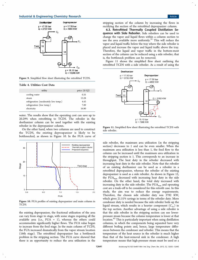
water. The results show that the operating cost can save up to20.29% when retrofitting to TCDS. The reboiler in thedeethanizer column can be used together with the existingreboiler in the depropanizer column.On the other hand, when two columns are used to construct
the TCDS, the existing deproapanizer is likely to bebottlenecked, as shown in Figure 10. In the FUA curve of
the existing depropanizer, the fractional utilization of the areacan vary from stage to stage, with some stages requiring all theavailable area (i.e., FUA = 1), whereas the others couldaccommodate significantly higher flows. The FUA value beganto increase from the feed stage. In the main column of TCDS,the FUA increased dramatically from the vapor stream location(16th stage). The retrofitted depropanizer has a bottleneckproblem in the stripping section. The FUA curve showed thatthere is an opportunity to reduce the area utilization in the
stripping section of the column by increasing the flows inrectifying the section of the retrofitted depropanizer column.
6.3. Retrofitted Thermally Coupled Distillation Se-quence with Side Reboiler. Side reboilers can be used tochange the vapor and liquid flows within a column section touse the area available more uniformly.32 This will reduce thevapor and liquid traffic below the tray where the side reboiler isplaced and increase the vapor and liquid traffic above the tray.Therefore, the liquid and vapor traffic in the bottom-mostsection of the column can be reduced using a side reboiler; thatis, the bottleneck problem can be removed.Figure 11 shows the simplified flow sheet outlining the
retrofitted TCDS with a side reboiler. As a result of using the
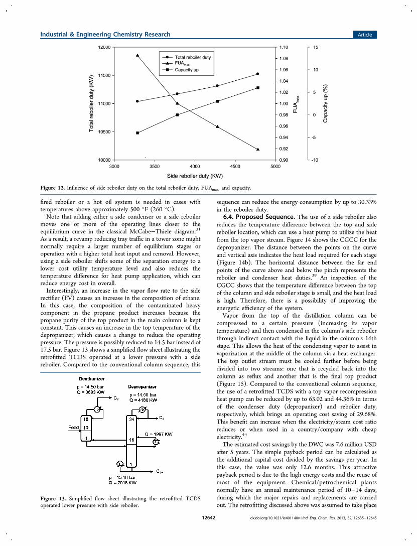
side reboiler, the maximum area utilization (in the strippingsection) decreases to 1 and can be even smaller. When themaximum area utilization is less than 1, the feed flow to thecolumn can be increased until the maximum area utilization inthe stripping section is 1. This corresponds to an increase inthroughput. The heat duty in the reboiler decreased withincreasing heat duty in the side reboiler. Note that the reboilerof an existing deethanizer can be used as a reboiler in aretrofitted depropanizer, whereas the reboiler of the existingdepropanizer is used as a side reboiler. As shown in Figure 12,the FUAmax decreased with increasing heat duty in the sidereboiler. On the other hand, the total duty increased withincreasing duty in the side reboiler. The FUAmax and operatingcost are a trade-off to be considered for this retrofit case. In thisstudy, the aim was to reduce the energy requirements.Therefore, the chosen side reboiler duty was 3782 KW,which gives 21.51% savings in terms of the reboiler duty. Morecondenser duty is needed because the side reboiler boils up theliquid stream, which results in a heavier component (C4+) inthe top section. Another advantage of using a side reboiler isthat the side reboiler in the stripping section can use lower-pressure steam because the column temperature is lower at thatlocation.43 This is particularly important when using distillationcolumns, in which the components being separated have verydifferent boiling points and, hence, large temperature differ-ences between the condenser and reboiler. This means that thetemperature of the heat source in the reboiler is much higherthan that of the heat-removal sink in the condenser. A hightemperature means that high-pressure steam must be used or a
Figure 9. Simplified flow sheet illustrating the retrofitted TCDS.
Table 4. Utilities Cost Data
utility price ($/GJ)
cooling water 0.35steam 13.28refrigeration (moderately low temp.) 4.43refrigeration (low temp.) 7.89electricity 16.80
Figure 10. FUA profiles of existing depropanizer and main column inTCDS.
Figure 11. Simplified flow sheet illustrating the retrofitted TCDS withside reboiler.
Industrial & Engineering Chemistry Research Article
dx.doi.org/10.1021/ie401140v | Ind. Eng. Chem. Res. 2013, 52, 12635−1264512641
fired reboiler or a hot oil system is needed in cases withtemperatures above approximately 500 °F (260 °C).Note that adding either a side condenser or a side reboiler
moves one or more of the operating lines closer to theequilibrium curve in the classical McCabe−Thiele diagram.31
As a result, a revamp reducing tray traffic in a tower zone mightnormally require a larger number of equilibrium stages oroperation with a higher total heat input and removal. However,using a side reboiler shifts some of the separation energy to alower cost utility temperature level and also reduces thetemperature difference for heat pump application, which canreduce energy cost in overall.Interestingly, an increase in the vapor flow rate to the side
rectifier (FV) causes an increase in the composition of ethane.In this case, the composition of the contaminated heavycomponent in the propane product increases because thepropane purity of the top product in the main column is keptconstant. This causes an increase in the top temperature of thedepropanizer, which causes a change to reduce the operatingpressure. The pressure is possibly reduced to 14.5 bar instead of17.5 bar. Figure 13 shows a simplified flow sheet illustrating theretrofitted TCDS operated at a lower pressure with a sidereboiler. Compared to the conventional column sequence, this
sequence can reduce the energy consumption by up to 30.33%in the reboiler duty.
6.4. Proposed Sequence. The use of a side reboiler alsoreduces the temperature difference between the top and sidereboiler location, which can use a heat pump to utilize the heatfrom the top vapor stream. Figure 14 shows the CGCC for thedepropanizer. The distance between the points on the curveand vertical axis indicates the heat load required for each stage(Figure 14b). The horizontal distance between the far endpoints of the curve above and below the pinch represents thereboiler and condenser heat duties.39 An inspection of theCGCC shows that the temperature difference between the topof the column and side reboiler stage is small, and the heat loadis high. Therefore, there is a possibility of improving theenergetic efficiency of the system.Vapor from the top of the distillation column can be
compressed to a certain pressure (increasing its vaportemperature) and then condensed in the column’s side reboilerthrough indirect contact with the liquid in the column’s 16thstage. This allows the heat of the condensing vapor to assist invaporization at the middle of the column via a heat exchanger.The top outlet stream must be cooled further before beingdivided into two streams: one that is recycled back into thecolumn as reflux and another that is the final top product(Figure 15). Compared to the conventional column sequence,the use of a retrofitted TCDS with a top vapor recompressionheat pump can be reduced by up to 63.02 and 44.36% in termsof the condenser duty (depropanizer) and reboiler duty,respectively, which brings an operating cost saving of 29.68%.This benefit can increase when the electricity/steam cost ratioreduces or when used in a country/company with cheapelectricity.44
The estimated cost savings by the DWC was 7.6 million USDafter 5 years. The simple payback period can be calculated asthe additional capital cost divided by the savings per year. Inthis case, the value was only 12.6 months. This attractivepayback period is due to the high energy costs and the reuse ofmost of the equipment. Chemical/petrochemical plantsnormally have an annual maintenance period of 10−14 days,during which the major repairs and replacements are carriedout. The retrofitting discussed above was assumed to take place
Figure 12. Influence of side reboiler duty on the total reboiler duty, FUAmax, and capacity.
Figure 13. Simplified flow sheet illustrating the retrofitted TCDSoperated lower pressure with side reboiler.
Industrial & Engineering Chemistry Research Article
dx.doi.org/10.1021/ie401140v | Ind. Eng. Chem. Res. 2013, 52, 12635−1264512642

within this maintenance period. Therefore, the production lossduring the retrofitting time was not considered.22
7. CONCLUSIONSThis paper reported a systematic and efficient approach forretrofit design to debottleneck the retrofitted TCDS. Ahydraulic performance indicator−fractional utilization of thearea and a side reboiler or a side condenser were used toidentify and remove the bottleneck problem in retrofittedTCDS effectively, respectively. The FUA curve, a graphical tool,showed where the area available for vapor flows can provideopportunities for the redistribution of flows within the maincolumn of TCDS. The FUA curve provides a vision forremoving the bottlenecks in the retrofitted TCDS. The sidereboiler and condenser were emphasized to change the vaporand liquid flows within a column section to utilize the availablearea. Retrofitting of the existing conventional distillationsequence can achieve significant energy savings with fewmodifications. The predicted RSM results showed goodagreement with a rigorous simulation. Furthermore, retrofittingto a TCDS with a side reboiler or a side condenser could notonly utilize the existing columns but also increase the processcapacity. This also increases the feasibility to apply the heatpump. The results showed that incorporating a heat pump tothe retrofitted TCDS, which includes internal and external heatintegration, is an attractive option for improved energy savings.
■ APPENDIX. HEAT EXCHANGER AND HEAT PUMPCOST CORRELATIONS
a. Capital cost: Guthrie’s modular method was applied.45 Inthis study, the Chemical Engineering Plant Cost Index of585.7 (2011) was used for cost updating.
= ×
× + −
updated bare module cost (BMC) UF BC
(MPF MF 1) (4)
=
where UF is the update factor:
UFpresent cost index
base cost index (5)
= ×α⎛
⎝⎜⎞⎠⎟
AA
BC is the bare cost for the heat exchanger:
BC BC00 (6)
=Δ
AQ
U Tarea of heat exchanger,
(7)
= ×α⎛
⎝⎜⎞⎠⎟
SS
for the compressor: BC BC00 (8)
where MPF is the material and pressure factor; MF is themodule factor (typical value), which is affected by thebase cost. A and S are the area and brake horsepower,respectively.
= + +F F Fmaterial and pressure factor: MPF m s m(9)
b. Operating cost (Op):
= + + +C C C COp steam refrigeration CW electricity (10)
where Csteam is the cost of the steam; Crefrigeration is thecost of refrigeration; CCW is the cost of cooling water;and Celectricity is the cost of electricity.
Figure 14. CGCC for retrofitted TCDS.
Figure 15. Simplified flow sheet illustrating the retrofitted TCDS withtop vapor recompression heat pump (proposed sequence).
Industrial & Engineering Chemistry Research Article
dx.doi.org/10.1021/ie401140v | Ind. Eng. Chem. Res. 2013, 52, 12635−1264512643

c.
= −cost saving energy cost saving modification cost(11)
d.
=payback period cost of project/saving per year(12)
■ AUTHOR INFORMATIONCorresponding Author†Telephone: +82-53-810-2512. E-mail: [email protected] authors declare no competing financial interest.
■ ACKNOWLEDGMENTSThis research was supported by a grant from the Gas PlantR&D Center funded by the Ministry of Land, Transportation,and Maritime Affairs (MLTM) of the Korean government.
■ REFERENCES(1) Liu, Z. Y.; Jobson, M. Retrofit Design for Increasing theProcessing Capacity of Distillation Columns 1. A Hydraulic Perform-ance Indicator. Chem. Eng. Res. Des. 2004, 82, 3−9.(2) Bravo-Bravo, C.; Segovia-Hernandez, J.; Gutierrez-Antonio, C.;Duran, A.; Bonilla-Petriciolet, A.; Briones-Ramirez, A. ExtractiveDividing Wall Column: Design and Optimization. Ind. Eng. Chem. Res.2010, 49, 3672−3688.(3) Long, N. V. D.; Lee, S. H.; Lee, M. Y. Design and Optimization ofa Dividing Wall Column for Debottlenecking of the Acetic AcidPurification. Chem. Eng. Process 2010, 49, 825−835.(4) Agrawal, R.; Fidkowski, Z. T. New Thermally Coupled Schemesfor Ternary Distillation. AIChE J. 1999, 45, 485−496.(5) Fidkowski, Z.; Krolikowski, L. Thermally Coupled System ofDistillation Columns: Optimization Procedure. AIChE J. 1986, 32,537−546.(6) Fidkowski, Z.; Krolikowski, L. Minimum Energy Requirements ofThermally Coupled Distillation Systems. AIChE J. 1987, 33, 643−654.(7) Long, N. V. D.; Lee, M. Y. Optimal Retrofit Design of ExtractiveDistillation to Energy Efficient Thermally Coupled DistillationScheme. AIChE J. 2013, 59, 1175−1182.(8) Long, N. V. D.; Lee, M. Y. Design and Optimization of a DividingWall Column Structure by Factorial Design. Korean J. Chem. Eng.2012, 29, 567−573.(9) Blancarte-Palacios, J. L.; Bautista-Valades, M. N.; HernandezCastro, S.; Rico-Ramírez, V.; Jimenez, A. Energy-Efficient Designs ofThermally Coupled Distillation Sequences for Four-ComponentMixtures. Ind. Eng. Chem. Res. 2003, 42, 5157−5164.(10) Tamayo-Galvan, V. E.; Segovia-Hernandez, J. G.; Hernandez, S.;Cabrera-Ruiz, J.; Alcantara-Avila, J. R. Controllability Analysis ofAlternate Schemes to Complex Column Arrangements with ThermalCoupling for the Separation of Ternary Mixtures. Com. Chem. Eng.2008, 32, 3057−3066.(11) Tedder, D. W.; Rudd, D. F. Parametric Studies in IndustrialDistillation: Part I. Design Comparisons. AIChE J. 1978, 24, 303−315.(12) Lee, S. H.; Shamsuzzoha, M.; Han, M.; Kim, Y. H.; Lee, M. Y.Study of Structural Characteristics of a Divided Wall Column using theSloppy Distillation Arrangement. Korean J. Chem. Eng. 2011, 28, 348−356.(13) Long, N. V. D.; Lee, M. Y. Improvement of Natural Gas LiquidRecovery Energy Efficiency through Thermally Coupled DistillationArrangements. Asia-Pac. J. Chem. Eng. 2012, 7, S71−S77.(14) Lee, S. G.; Long, N. V. D.; Lee, M. Y. Design and Optimizationof Natural Gas Liquefaction and Recovery Processes for OffshoreFloating Liquid Natural Gas Plants. Ind. Eng. Chem. Res. 2012, 51,10021−10030.
(15) Long, N. V. D.; Lee, M. Y. Optimal Retrofit of a Side StreamColumn to a Dividing Wall Column for Energy Efficiency Max-imization. Chem. Eng. Res. Des. 2013 , DOI: 10.1016/j.cherd.2013.04.003.(16) Long, N. V. D.; Lee, M. Y. Improvement of the Deethanizingand Depropanizing Fractionation Steps in NGL Recovery Processusing Dividing Wall Column. J. Chem. Eng. Jpn. 2012, 45, 285−294.(17) Shizou, M.; Zheng, S. N.; Ikuho, Y. Analysis of Divided-WallColumn for Extractive Distillation. Kagaku Kogaku Ronbunshu 2000,26, 627−632.(18) Ibarra-Sanchez, J. d. J.; Segovia-Hernandez, J. G. ReducingEnergy Consumption and CO2 Emissions in Extractive Distillation:Part II. Dynamic Behavior. Chem. Eng. Res. Des. 2010, 88, 135−145.(19) Gutierrez-Guerraa, R.; Segovia-Hernandez, J. G.; Hernandez, S.Reducing Energy Consumption and CO2 Emissions in ExtractiveDistillation. Chem. Eng. Res. Des. 2009, 87, 145−152.(20) Amminudin, K. A.; Smith, R. Design and Optimization of FullyThermally Coupled Distillation Columns. Part 2: Application ofDividing Wall Columns in Retrofit. Chem. Eng. Res. Des. 2001, 79,716−724.(21) Long, N. V. D.; Lee, M. Y. Improved Energy Efficiency inDebottlenecking Using a Fully Thermally Coupled DistillationColumn. Asia-Pac. J. Chem. Eng. 2011, 6, 338−348.(22) Premkumar, R.; Rangaiah, G. P. Retrofitting ConventionalColumn Systems to Dividing Wall Columns. Chem. Eng. Res. Des.2009, 87, 47−60.(23) Triantafyllou C. The Design Optimization and Integration ofDividing Wall Distillation Columns. Ph. D. Thesis, UMIST,Manchester, U.K., 1991.(24) Gadalla, M.; Jobson, M.; Smith, R. Shortcut Models for RetrofitDesign of Distillation Columns. Chem. Eng. Res. Des. 2003, 81, 971−986.(25) Box, G. E. P.; Wilson, K. B. On the Experimental Attainment ofOptimum Conditions. J. R. Stat. Soc. Ser. B 1951, 13, 1−45.(26) Box, G. E. P.; Behnken, D. W. Some New Three Level Designsfor The Study of Quantitative Variables. Technometrics 1960, 2, 455−475.(27) Erbay, Z.; Icier, F. Optimization of Hot Air Drying of OliveLeaves using Response Surface Methodology. J. Food Eng. 2009, 91,533−541.(28) Long, N. V. D.; Lee, M. Y. Dividing Wall Column StructureDesign using Response Surface Methodology. Com. Chem. Eng. 2012,37, 119−124.(29) Mannan, S.; Fakhru’l-Razi, A.; Alam, M. Z. Optimization ofProcess Parameters for The Bioconversion of Activated Sludge byPenicillium Corylophilum, Using Response Surface Methodology. J.Environ. Sci. 2007, 19, 23−28.(30) Kister, H. Z. Distillation Design; McGraw-Hill: New York, 1992;pp 336−337.(31) Reid, J. A. Distributed Distillation with Heat Integration. PTQAUTUMN 2000 2000, 85−95.(32) Liu, Z. Y.; Jobson, M. Retrofit Design for Increasing theProcessing Capacity of Distillation Columns. 2. Proposing andEvaluating Design Options. Chem. Eng. Res. Des. 2004, 82, 10−17.(33) Dhole, V. R.; Linnhoe, B. Distillation Column Targets. Com.Chem. Eng. 1993, 17, 549−560.(34) Franklin, N. L.; Wilkinson, M. B. Reversibility in the Separationof Multicomponent Mixtures. Trans. Int. Chem. Eng. 1982, 60, 276−282.(35) Terranova, B. E. A.; Westberg, W. Temperature-Heat Diagramsfor Complex Columns. 1. Intercooled/Interheated DistillationColumns. Int. Eng. Chem. Res. 1989, 28, 1374−1379.(36) Fitzmorris, R. E.; Mah, R. S. H. Improving Distillation ColumnDesign using Thermodynamic Availability Analysis. AIChE J. 1980, 26,265−273.(37) Fonyo, Z. Thermodynamic Analysis of Rectification. I.Reversible Model of Rectification. Int. Chem. Eng. 1974, 14, 18−27.(38) Fonyo, Z. Thermodynamic Analysis of Rectification. II. FiniteCascade Models. Int. Chem. Eng. 1974, 14, 203−210.
Industrial & Engineering Chemistry Research Article
dx.doi.org/10.1021/ie401140v | Ind. Eng. Chem. Res. 2013, 52, 12635−1264512644

(39) Rivera-Ortega, P.; Picon-Nunez, M.; Torres-Reyes, E.; Gallegos-Munoz, A. Thermal Integration of Heat Pumping Systems inDistillation Columns. Appl. Thermal Eng. 1999, 19, 819−829.(40) Manley, D. B. Deethanizer/Depropanizer Sequences withThermal and Thermo-Mechanical Coupling and Component Dis-tribution. U.S. Patent No. 5,673,571, 1997.(41) Aspen HYSYS Thermodynamics COM Interface, Version V7.1;Aspen Technology: Burlington, MA, 2009.(42) Turton, R.; Bailie, R. C.; Whiting, W. B.; Shaeiwitz, J. A;Bhattacharyya, D. Analysis, Synthesis, and Design of Chemical Processes,4th ed.; Prentice Hall: Upper Saddle River, NJ, 2012; pp 187−220.(43) Luyben, W. L. Design and Control of Distillation Columns withIntermediate Reboiler. Ind. Eng. Chem. Res. 2004, 43, 8244−8250.(44) Long, N. V. D.; Lee, M. Y. Design and Optimization of HeatIntegrated Dividing Wall Columns for Improved Debutanizing andDeisobutanizing Fractionation of NGL. Korean J. Chem. Eng. 2013, 30,286−294.(45) Biegler, L. T.; Grossmann, I. E.; Westerberg, A. W. SystematicMethods of Chemical Process Design; Prentice Hall Inc.: Upper SaddleRiver, NJ, 1997; pp 110−141.
Industrial & Engineering Chemistry Research Article
dx.doi.org/10.1021/ie401140v | Ind. Eng. Chem. Res. 2013, 52, 12635−1264512645


![Multimodal chromatography: debottlenecking the downstream ... · Multimodal chromatography: debottlenecking the downstream processing of monoclonal antibodies Review step [17] in](https://img.pdfslide.us/doc/110x75/5b92e15f09d3f232708cb3b1/multimodal-chromatography-debottlenecking-the-downstream-multimodal-chromatography.jpg)