Embed Size (px)
DESCRIPTION
control
Citation preview
Chinese Journal of Aeronautics
Chinese Journal of Aeronautics 20(2007) 266-271www.elsevier.com/locate/cja
Development of PLC-based Tension Control System REN Sheng-le*, LU Hua, WANG Yong-zhang, FU Hong-ya
Department of Mechanical Engineering, Harbin Institute of Technology, Harbin 150001, China
Received 22 May 2006; accepted 22 November 2006
Abstract
Fiber winding tension is an important factor in the molding techniques of composite material which influences the quality of
winding product directly, and the tension control is a key technique in fiber winding techniques. This paper introduces a closed-loop
tension control system with the programmable logic controller (PLC) with function modules as its control kernel, the alternating current
(AC) servo motor as execute element and the radius-following device to accomplish the real-time radius compensation. The mechanism
of the tension control system is analyzed and the numerical model is set up. The compensation technique of the radius of the scroll is
analyzed. Experimental results show that the system is well qualified with high control precision and high reaction speed.
Keywords: tension control; PLC; numerical control winding machine; AC digital servo motor
*The components of composite material fiber winding possess such advantages as low weight, high strength, and high corrosion resistance, and they are widely applied in aviation and aerospace industry. Many researches have shown that im-proper or unstable tension leads to a strength loss of 20%-30% of the fiber wound components. An ideal tension control system should provide stable and adjustable tension during the winding process [1-3].
With the development of the winding machine, tension controllers have, so far, undergone three stages of development, i.e., mechanical tension con-troller, electrical tension controller and computer-ized tension controller[4-5]. With the development of electronic technology and the appearance of the microprocessor of higher cost performance, com-puterized tension controller came into use. Micro-processor becomes the kernel of the control system and thus cuts down the number of circuits of the electronic control system, which greatly simplifies
*Corresponding author. Tel.: +86-451-86413812. E-mail address: [email protected] Foundation item: National Natural Science Foundation of China (50175020)
the system, improves its reliability and makes pos-sible the application of advanced control methods. Therefore, this type of controllers is widely used[6-7].
The tension control techniques are becoming mature and the specifications are being improved in some developed countries. However, the fiber wind-ing industry of China started up late and still drops behind compared with the western countries.
Mechanical tensioners, with low precision and slow response, account for the main part of domes-tically-applied tensioners, and cannot meet the ten-sion requirements. Therefore, this paper presents a PLC-based tension control system.
1 Set-up of the System Scheme
1.1 Construction of the system
A winding tension control system generally consists of three main parts, namely the unwinder, the processer and the winder, and it may also in-clude the measuring and control parts, ancillary transport apparatus, and a load cell. The type of the winder and that of the unwinder may be one of the
REN Sheng-le et al. / Chinese Journal of Aeronautics 20(2007) 266-271 · 267 ·
two drive types, surface drive or center drive. The surface drive means that a scroll or belt is set on the surface of the winding material and the drive force is generated through friction. The center drive is to set a drive mechanism on the center shaft of the scroll, where the linear speed and the tension force of the winding fiber vary with the radius of the scroll, leading to the so-called “scroll thick”[8]. The phenomenon of “scroll thick” makes the tension control very complex, but the center drive mode is widely applied due to its wide applicability.
1.2 Design of tension control scheme
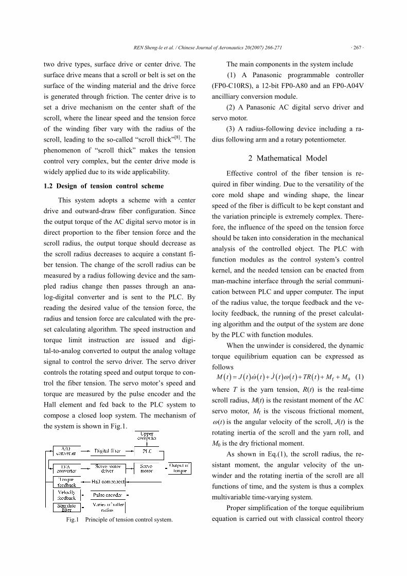
This system adopts a scheme with a center drive and outward-draw fiber configuration. Since the output torque of the AC digital servo motor is in direct proportion to the fiber tension force and the scroll radius, the output torque should decrease as the scroll radius decreases to acquire a constant fi-ber tension. The change of the scroll radius can be measured by a radius following device and the sam-pled radius change then passes through an ana-log-digital converter and is sent to the PLC. By reading the desired value of the tension force, the radius and tension force are calculated with the pre-set calculating algorithm. The speed instruction and torque limit instruction are issued and digi-tal-to-analog converted to output the analog voltage signal to control the servo driver. The servo driver controls the rotating speed and output torque to con-trol the fiber tension. The servo motor’s speed and torque are measured by the pulse encoder and the Hall element and fed back to the PLC system to compose a closed loop system. The mechanism of the system is shown in Fig.1.
Fig.1 Principle of tension control system.
The main components in the system include (1) A Panasonic programmable controller
(FP0-C10RS), a 12-bit FP0-A80 and an FP0-A04V ancilliary conversion module.
(2) A Panasonic AC digital servo driver and servo motor.
(3) A radius-following device including a ra-dius following arm and a rotary potentiometer.
2 Mathematical Model
Effective control of the fiber tension is re-quired in fiber winding. Due to the versatility of the core mold shape and winding shape, the linear speed of the fiber is difficult to be kept constant and the variation principle is extremely complex. There- fore, the influence of the speed on the tension force should be taken into consideration in the mechanical analysis of the controlled object. The PLC with function modules as the control system’s control kernel, and the needed tension can be enacted from man-machine interface through the serial communi- cation between PLC and upper computer. The input of the radius value, the torque feedback and the ve-locity feedback, the running of the preset calculat-ing algorithm and the output of the system are done by the PLC with function modules.
When the unwinder is considered, the dynamic torque equilibrium equation can be expressed as follows
( ) ( ) ( ) ( ) ( ) ( ) f 0M t J t t J t t TR t M Mω ω= + + + + (1)
where T is the yarn tension, R(t) is the real-time scroll radius, M(t) is the resistant moment of the AC servo motor, Mf is the viscous frictional moment,
( )tω is the angular velocity of the scroll, J(t) is the rotating inertia of the scroll and the yarn roll, and M0 is the dry frictional moment.
As shown in Eq.(1), the scroll radius, the re-sistant moment, the angular velocity of the un-winder and the rotating inertia of the scroll are all functions of time, and the system is thus a complex multivariable time-varying system.
Proper simplification of the torque equilibrium equation is carried out with classical control theory
· 268 · REN Sheng-le et al. / Chinese Journal of Aeronautics 20(2007) 266-271
based on the following rules: (1) The dry frictional moment and the viscous
frictional moment are very little and may be ig-nored.
(2) The influence of ( ) ( )J t tω on the tension force may be ignored since the instantaneous inertia changes very slightly.
(3) The scroll radius is real-time measured and fed back by the radius following device.
Eq.(1) is then simplified as ( ) ( )( ) ( )TR t M t J t tω= + (2)
Therefore, the variations of scroll diameter and scroll angular velocity are the main influencing fac-tors of the yarn tension.
3 Compensation of the Radius of the Scroll
The radius change of the scroll causes the change of the scroll moment, i.e., the change of the
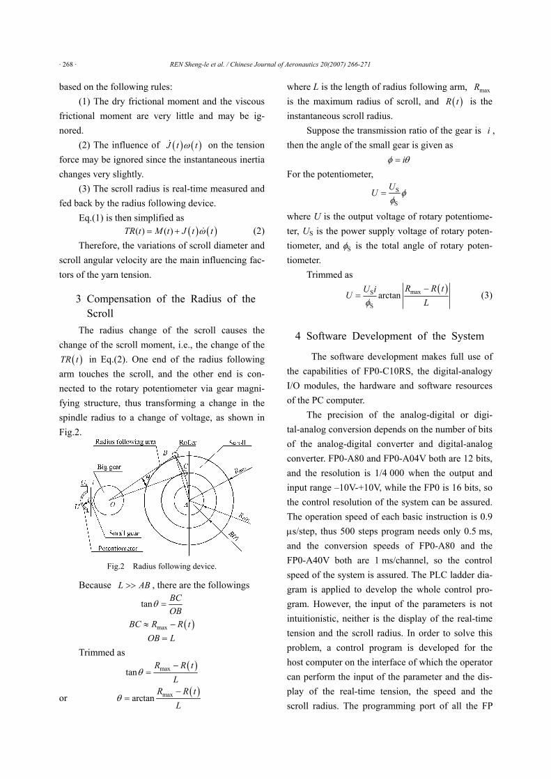
( )TR t in Eq.(2). One end of the radius following arm touches the scroll, and the other end is con-nected to the rotary potentiometer via gear magni-fying structure, thus transforming a change in the spindle radius to a change of voltage, as shown in Fig.2.
Fig.2 Radius following device.
Because L AB>> , there are the followings
tan BCOB
θ =
( )maxBC R R t≈ − OB L=
Trimmed as ( )maxtan
R R tL
θ−
=
or ( )maxarctanR R t
Lθ
−=
where L is the length of radius following arm, maxR is the maximum radius of scroll, and ( )R t is the instantaneous scroll radius.
Suppose the transmission ratio of the gear is i , then the angle of the small gear is given as
iφ θ= For the potentiometer,
S
S
UU φ
φ=
where U is the output voltage of rotary potentiome-ter, US is the power supply voltage of rotary poten-tiometer, and Sφ is the total angle of rotary poten-tiometer.
Trimmed as
( )maxS
Sarctan
R R tU iU
Lφ−
= (3)
4 Software Development of the System
The software development makes full use of the capabilities of FP0-C10RS, the digital-analogy I/O modules, the hardware and software resources of the PC computer.
The precision of the analog-digital or digi-tal-analog conversion depends on the number of bits of the analog-digital converter and digital-analog converter. FP0-A80 and FP0-A04V both are 12 bits, and the resolution is 1/4 000 when the output and input range –10V-+10V, while the FP0 is 16 bits, so the control resolution of the system can be assured. The operation speed of each basic instruction is 0.9 μs/step, thus 500 steps program needs only 0.5 ms, and the conversion speeds of FP0-A80 and the FP0-A40V both are 1 ms/channel, so the control speed of the system is assured. The PLC ladder dia-gram is applied to develop the whole control pro-gram. However, the input of the parameters is not intuitionistic, neither is the display of the real-time tension and the scroll radius. In order to solve this problem, a control program is developed for the host computer on the interface of which the operator can perform the input of the parameter and the dis-play of the real-time tension, the speed and the scroll radius. The programming port of all the FP
REN Sheng-le et al. / Chinese Journal of Aeronautics 20(2007) 266-271 · 269 ·
PLC’s support OPEN MEWTOCOL PROTOCOL. Upper computer sends a COMMAND to PLC as an ASCLL string. Then the PLC automatically returns the RESPONSE based on the COMMAND.
COMMAND format % Station
number # Command Text data
Check code
Termi-nater
RESPONSE format % Station
number $ Command Text data
Check code
Termi-nater
RESPONSE format on Error % Station num-
ber ! Error Check code Termi-nater
%: This is a fixed character. All the previous uncompleted text strings are ignored when PLC re-ceives “%” which means the beginning of the next command.
#, $, !: Indicate what the string is: COM-MAND(#), RESPONSE($) or ERROR RE-SPONSE(!).
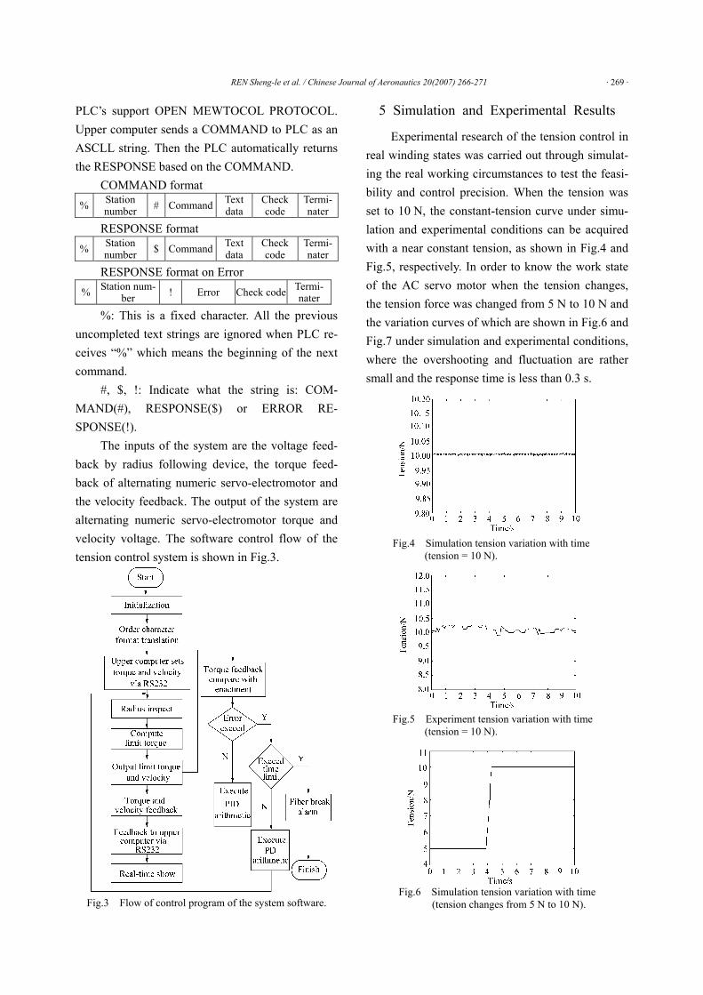
The inputs of the system are the voltage feed-back by radius following device, the torque feed-back of alternating numeric servo-electromotor and the velocity feedback. The output of the system are alternating numeric servo-electromotor torque and velocity voltage. The software control flow of the tension control system is shown in Fig.3.
Fig.3 Flow of control program of the system software.
5 Simulation and Experimental Results
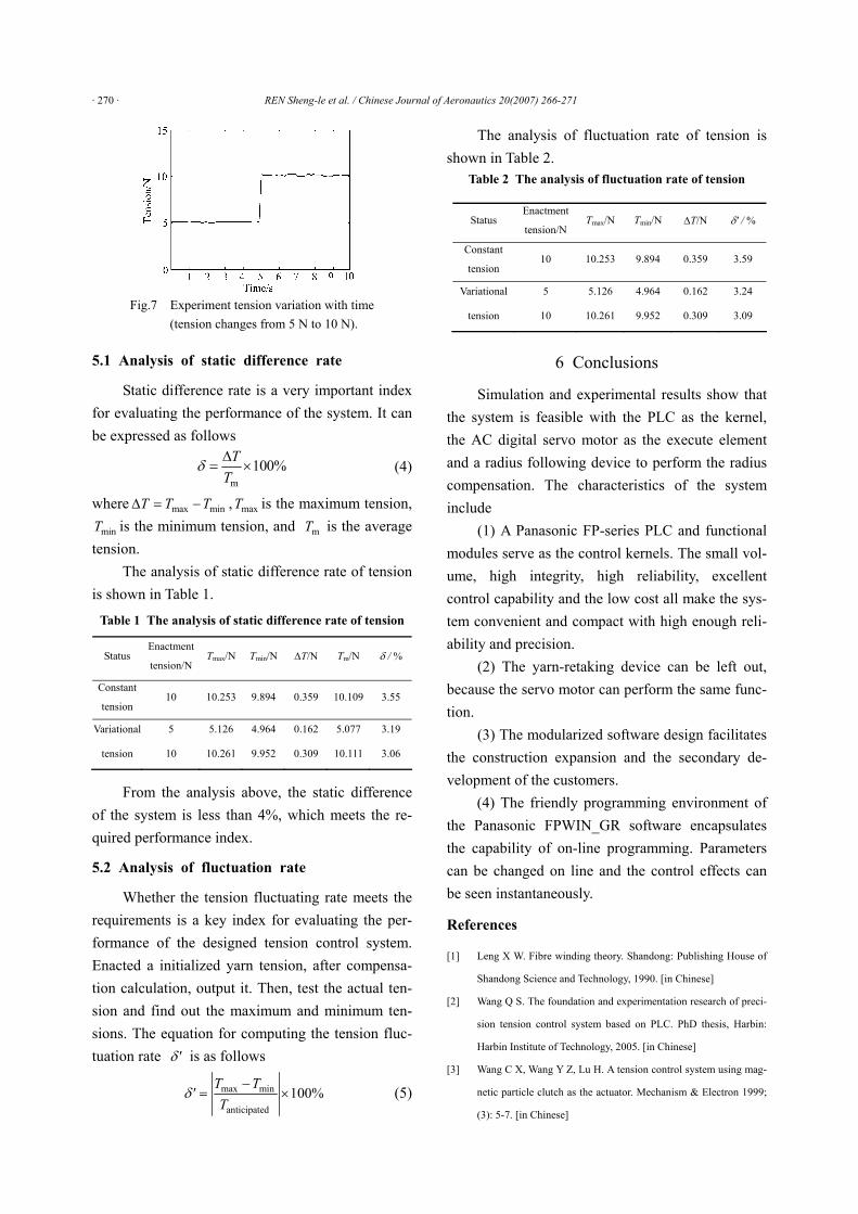
Experimental research of the tension control in real winding states was carried out through simulat-ing the real working circumstances to test the feasi-bility and control precision. When the tension was set to 10 N, the constant-tension curve under simu-lation and experimental conditions can be acquired with a near constant tension, as shown in Fig.4 and Fig.5, respectively. In order to know the work state of the AC servo motor when the tension changes, the tension force was changed from 5 N to 10 N and the variation curves of which are shown in Fig.6 and Fig.7 under simulation and experimental conditions, where the overshooting and fluctuation are rather small and the response time is less than 0.3 s.
Fig.4 Simulation tension variation with time
(tension = 10 N).
Fig.5 Experiment tension variation with time
(tension = 10 N).
Fig.6 Simulation tension variation with time
(tension changes from 5 N to 10 N).
· 270 · REN Sheng-le et al. / Chinese Journal of Aeronautics 20(2007) 266-271
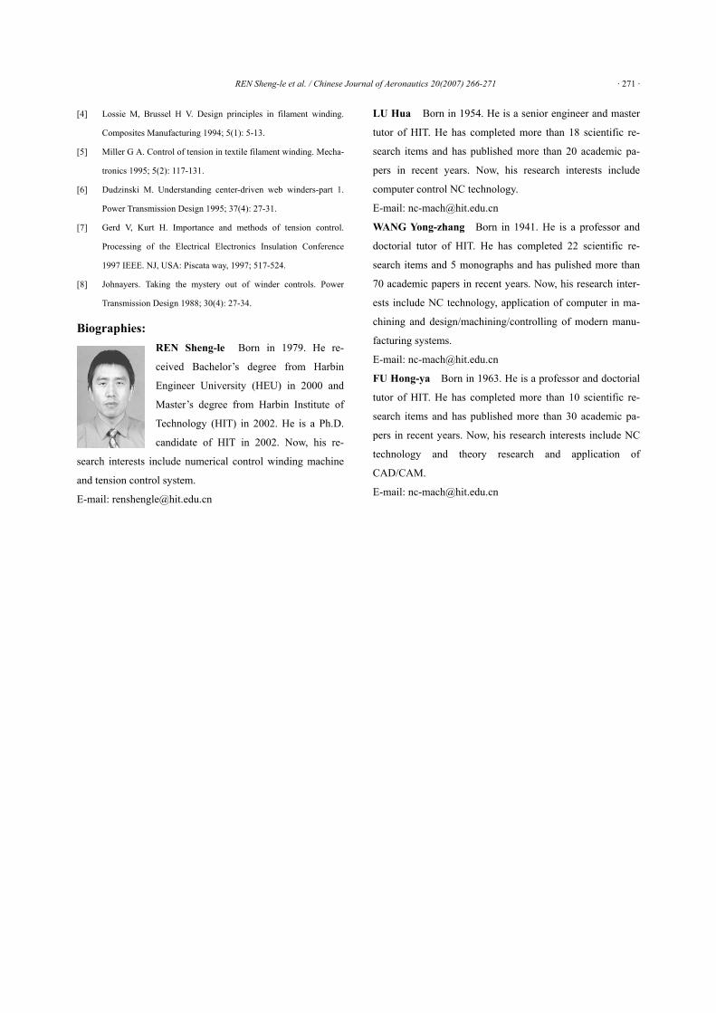
Fig.7 Experiment tension variation with time
(tension changes from 5 N to 10 N).
5.1 Analysis of static difference rate
Static difference rate is a very important index for evaluating the performance of the system. It can be expressed as follows
m100%T
Tδ Δ
= × (4)
where max minT T TΔ = − , maxT is the maximum tension,
minT is the minimum tension, and mT is the average tension.
The analysis of static difference rate of tension is shown in Table 1.
Table 1 The analysis of static difference rate of tension
Status Enactment
tension/N Tmax/N Tmin/N ΔT/N Tm/N δ / %
Constant
tension 10 10.253 9.894 0.359 10.109 3.55
Variational 5 5.126 4.964 0.162 5.077 3.19
tension 10 10.261 9.952 0.309 10.111 3.06
From the analysis above, the static difference of the system is less than 4%, which meets the re-quired performance index.
5.2 Analysis of fluctuation rate
Whether the tension fluctuating rate meets the requirements is a key index for evaluating the per-formance of the designed tension control system. Enacted a initialized yarn tension, after compensa-tion calculation, output it. Then, test the actual ten-sion and find out the maximum and minimum ten-sions. The equation for computing the tension fluc-tuation rate 'δ is as follows
max min
anticipated100%
T T'
Tδ
−= × (5)
The analysis of fluctuation rate of tension is shown in Table 2.
Table 2 The analysis of fluctuation rate of tension
6 Conclusions
Simulation and experimental results show that the system is feasible with the PLC as the kernel, the AC digital servo motor as the execute element and a radius following device to perform the radius compensation. The characteristics of the system include
(1) A Panasonic FP-series PLC and functional modules serve as the control kernels. The small vol-ume, high integrity, high reliability, excellent control capability and the low cost all make the sys-tem convenient and compact with high enough reli-ability and precision.
(2) The yarn-retaking device can be left out, because the servo motor can perform the same func-tion.
(3) The modularized software design facilitates the construction expansion and the secondary de-velopment of the customers.
(4) The friendly programming environment of the Panasonic FPWIN_GR software encapsulates the capability of on-line programming. Parameters can be changed on line and the control effects can be seen instantaneously.
References
[1] Leng X W. Fibre winding theory. Shandong: Publishing House of
Shandong Science and Technology, 1990. [in Chinese]
[2] Wang Q S. The foundation and experimentation research of preci-
sion tension control system based on PLC. PhD thesis, Harbin:
Harbin Institute of Technology, 2005. [in Chinese]
[3] Wang C X, Wang Y Z, Lu H. A tension control system using mag-
netic particle clutch as the actuator. Mechanism & Electron 1999;
(3): 5-7. [in Chinese]
Status Enactment
tension/NTmax/N Tmin/N ΔT/N δ' / %
Constant
tension 10 10.253 9.894 0.359 3.59
Variational 5 5.126 4.964 0.162 3.24
tension 10 10.261 9.952 0.309 3.09
REN Sheng-le et al. / Chinese Journal of Aeronautics 20(2007) 266-271 · 271 ·
[4] Lossie M, Brussel H V. Design principles in filament winding.
Composites Manufacturing 1994; 5(1): 5-13.
[5] Miller G A. Control of tension in textile filament winding. Mecha-
tronics 1995; 5(2): 117-131.
[6] Dudzinski M. Understanding center-driven web winders-part 1.
Power Transmission Design 1995; 37(4): 27-31.
[7] Gerd V, Kurt H. Importance and methods of tension control.
Processing of the Electrical Electronics Insulation Conference
1997 IEEE. NJ, USA: Piscata way, 1997; 517-524.
[8] Johnayers. Taking the mystery out of winder controls. Power
Transmission Design 1988; 30(4): 27-34.
Biographies: REN Sheng-le Born in 1979. He re-
ceived Bachelor’s degree from Harbin
Engineer University (HEU) in 2000 and
Master’s degree from Harbin Institute of
Technology (HIT) in 2002. He is a Ph.D.
candidate of HIT in 2002. Now, his re-
search interests include numerical control winding machine
and tension control system.
E-mail: [email protected]
LU Hua Born in 1954. He is a senior engineer and master
tutor of HIT. He has completed more than 18 scientific re-
search items and has published more than 20 academic pa-
pers in recent years. Now, his research interests include
computer control NC technology.
E-mail: [email protected]
WANG Yong-zhang Born in 1941. He is a professor and
doctorial tutor of HIT. He has completed 22 scientific re-
search items and 5 monographs and has pulished more than
70 academic papers in recent years. Now, his research inter-
ests include NC technology, application of computer in ma-
chining and design/machining/controlling of modern manu-
facturing systems.
E-mail: [email protected]
FU Hong-ya Born in 1963. He is a professor and doctorial
tutor of HIT. He has completed more than 10 scientific re-
search items and has published more than 30 academic pa-
pers in recent years. Now, his research interests include NC
technology and theory research and application of
CAD/CAM.
E-mail: [email protected]