Embed Size (px)
Citation preview
Installing and Testing a GFCI
Receptacle
Please read this leaflet completely before getting started.
DI-000-X7299-02A
CAUTION!1. What is a GFCI?
A GFCI receptacle is different from conventional receptacles. In the event of a ground fault, a GFCI will trip and quickly stop the flow of electricity to prevent serious injury.
Definition of a ground fault:Instead of following its normal safe path, electricity passes through a person's body to reach the ground. For example, a defective appliance can cause a ground fault.
A GFCI receptacle does NOT protect against circuit overloads, short circuits, or shocks. For example, you can still be shocked if you touch bare wires while standing on a non-conducting surface, such as a wood floor.
NOTE:GFCI's contain a lockout feature that will prevent RESET if:
• ThereisnopowerbeingsuppliedtotheGFCI.• TheGFCIismiswiredduetoreversalofthe
LINE and LOAD leads.• TheGFCIcannotpassitsinternaltest,
indicating that it may not be able to provide protection in the event of a ground fault.
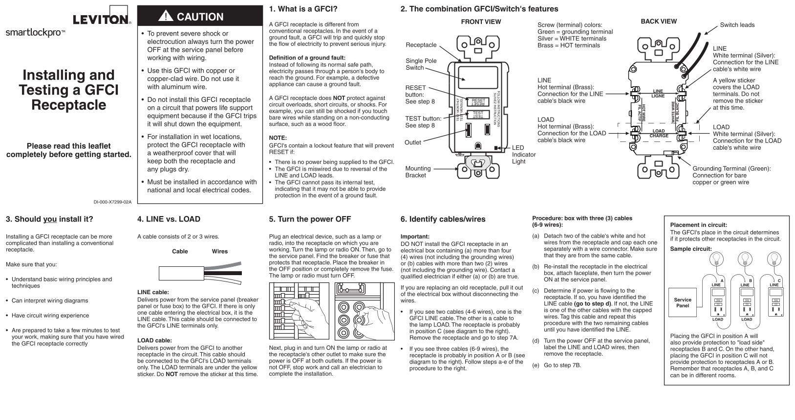
2. The combination GFCI/Switch's features
3. Should you install it?
Installing a GFCI receptacle can be more complicated than installing a conventional receptacle.
Make sure that you:
• Understandbasicwiringprinciplesandtechniques
• Caninterpretwiringdiagrams
• Havecircuitwiringexperience
• Arepreparedtotakeafewminutestotestyour work, making sure that you have wired the GFCI receptacle correctly
4. LINE vs. LOAD
A cable consists of 2 or 3 wires.
Cable Wires
LINE cable:Delivers power from the service panel (breaker panel or fuse box) to the GFCI. If there is only one cable entering the electrical box, it is the LINE cable. This cable should be connected to the GFCI's LINE terminals only.
LOAD cable:Delivers power from the GFCI to another receptacle in the circuit. This cable should be connected to the GFCI's LOAD terminals only. The LOAD terminals are under the yellow sticker. Do NOT remove the sticker at this time.
5. Turn the power OFF
Plug an electrical device, such as a lamp or radio, into the receptacle on which you are working. Turn the lamp or radio ON. Then, go to the service panel. Find the breaker or fuse that protects that receptacle. Place the breaker in the OFF position or completely remove the fuse. The lamp or radio must turn OFF.
Next, plug in and turn ON the lamp or radio at the receptacle's other outlet to make sure the power is OFF at both outlets. If the power is not OFF, stop work and call an electrician to complete the installation.
6. Identify cables/wires
Important:DO NOT install the GFCI receptacle in an electrical box containing (a) more than four (4) wires (not including the grounding wires) or (b) cables with more than two (2) wires (not including the grounding wire). Contact a qualified electrician if either (a) or (b) are true.
If you are replacing an old receptacle, pull it out of the electrical box without disconnecting the wires.
• Ifyouseetwocables(4-6wires),oneistheGFCI LINE cable. The other is a cable to the lamp LOAD. The receptacle is probably in position C (see diagram to the right). Remove the receptacle and go to step 7A.
• Ifyouseethreecables(6-9wires),thereceptacle is probably in position A or B (see diagram to the right). Follow steps a-e of the procedure to the right.
Procedure: box with three (3) cables (6-9 wires):
(a) Detach two of the cable's white and hot wires from the receptacle and cap each one separately with a wire connector. Make sure that they are from the same cable.
(b) Re-install the receptacle in the electrical box, attach faceplate, then turn the power ON at the service panel.
(c) Determine if power is flowing to the receptacle. If so, you have identified the LINE cable (go to step d). If not, the LINE is one of the other cables with the capped wires. Tag this cable and repeat this procedure with the two remaining cables until you have identified the LINE.
(d) Turn the power OFF at the service panel, label the LINE and LOAD wires, then remove the receptacle.
(e) Go to step 7B.
Placement in circuit:The GFCI's place in the circuit determines if it protects other receptacles in the circuit.
Sample circuit:
Placing the GFCI in position A will also provide protection to "load side" receptacles B and C. On the other hand, placing the GFCI in position C will not provide protection to receptacles A or B. Remember that receptacles A, B, and C can be in different rooms.
RESET RESET
TESTTEST
TE
ST
MO
NT
HLY
TE
ST
ME
NS
UE
L
FO
LLOW
INS
TR
UC
TIO
NS
SU
IVE
Z IN
ST
RU
CT
ION
FRONT VIEW
Receptacle
Single Pole Switch
TEST button: See step 8
LEDIndicatorLight
RESET button: See step 8
Mounting Bracket
Outlet
WH
ITE
WIR
EF
IL B
LA
NCH
OT
WIR
EF
IL A
CT
IF
CHARGELOAD
LIGNELINE
BACK VIEW
Grounding Terminal (Green):Connection for barecopper or green wire
LINEWhite terminal (Silver):Connection for the LINE cable's white wire
LOADWhite terminal (Silver):Connection for the LOAD cable's white wire
LINEHotterminal(Brass):Connection for the LINE cable's black wire
A yellow sticker covers the LOAD terminals. Do not remove the sticker at this time.
LOADHotterminal(Brass):Connection for the LOAD cable's black wire
Screw (terminal) colors:Green = grounding terminalSilver=WHITEterminalsBrass=HOTterminals
Switch leads
LINEA B C
LOAD
ServicePanel
LOAD
LINE LINE
RESETRESET
TESTTEST
RESETRESET
TESTTEST
RESETRESET
TESTTEST
• Topreventsevereshockorelectrocution always turn the power OFF at the service panel before working with wiring.
• UsethisGFCIwithcopperorcopper-clad wire. Do not use it with aluminum wire.
• DonotinstallthisGFCIreceptacleon a circuit that powers life support equipment because if the GFCI trips it will shut down the equipment.
• Forinstallationinwetlocations,protect the GFCI receptacle with a weatherproof cover that will keep both the receptacle and any plugs dry.
• Mustbeinstalledinaccordancewithnational and local electrical codes.
Connect the LINE cable wires to the LINE terminals:• ThewhitewireconnectstotheWHITEterminal(Silver).• TheblackwireconnectstotheHOTterminal(Brass).Connect the switch leads to the switch controlled LOAD (not GFCI protected, shown in diagram):• One black switch lead connects to the LINE side black wire.• TheotherblackleadconnectstotheHOTside of the LOAD.• TheLOADmustbeproperlyconnectedtoNEUTRALandgrounded.
NOTE: Wiring for switched LOAD shown here is only one of several options. If you are unsure about any part of these instructions, consult a qualified electrician.
Connect the grounding wire (only if there is a grounding wire):• Foraboxwithnogroundingterminal(diagramnotshown):ConnecttheLINEcable'sbarecopper
(or GREEN) wire directly to the grounding terminal on the GFCI receptacle.• Foraboxwithagroundingterminal(diagramshownabove):Connecta6-inchbarecopper(or
GREEN) 12 or 14 AWG wire to the grounding terminal on the GFCI. Also connect a similar wire to the grounding terminal on the box. Connect the ends of these wires to the LINE cable's bare copper (or GREEN) wire using a wire connector. If these wires are already in place, check the connections.
Complete the installation:• Foldthewiresintothebox,keepingthegroundingwireawayfromtheWHITEandHOTterminals.
Screw the receptacle to the box and attach the faceplate.• Gotostep8.
For Side wire - Loop clockwise 3/4 of the way around screw
For Back wire - Insert bare wire fully and tighten terminal clamp on conductor ONLY For Side wire - Loop
clockwise 3/4 of the way around screw
For Back wire - Insert bare wire fully and tighten terminal clamp on conductor ONLY
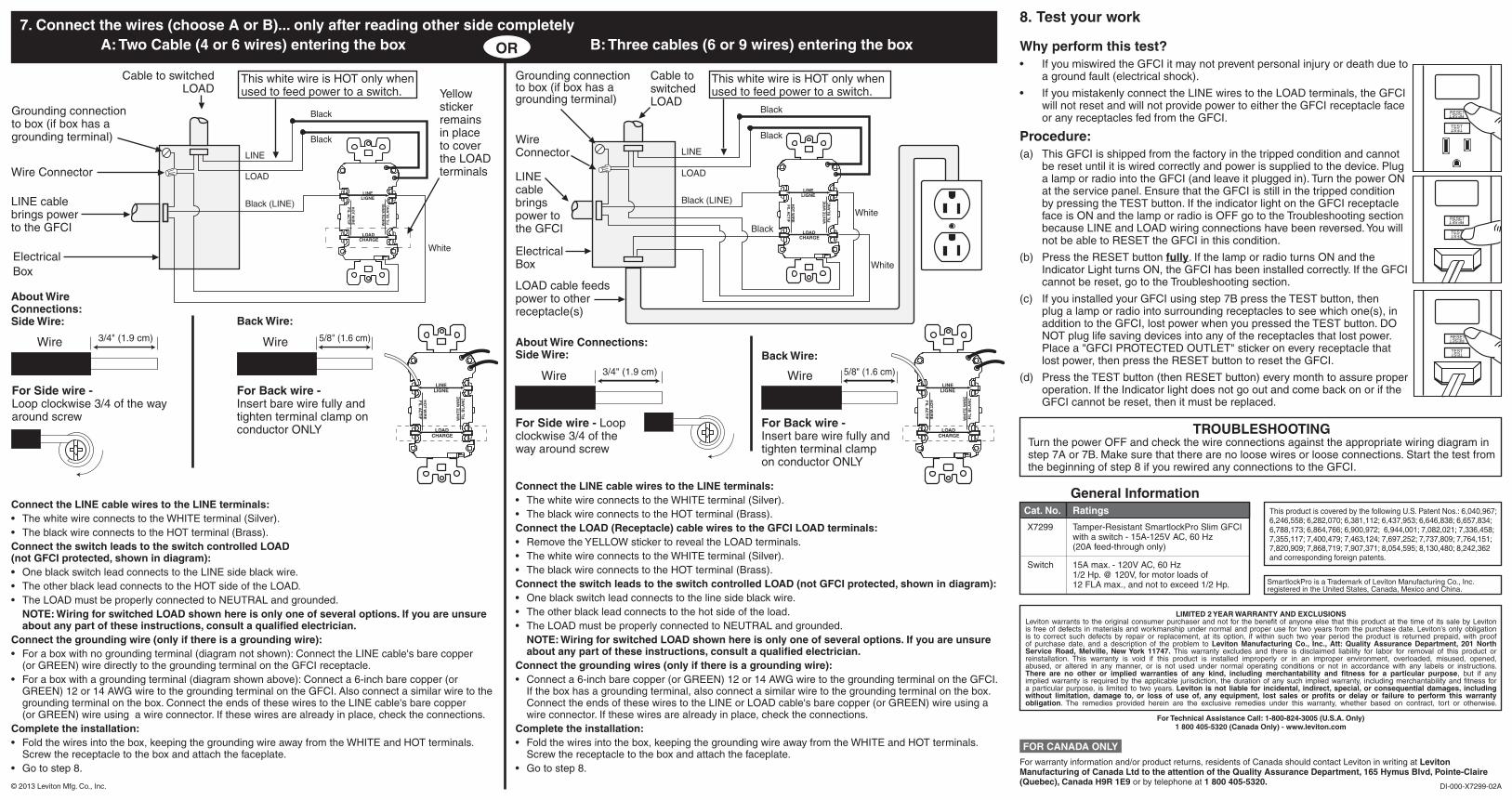
7. Connect the wires (choose A or B)... only after reading other side completely A: Two Cable (4 or 6 wires) entering the box OR B: Three cables (6 or 9 wires) entering the boxOR
8. Test your work
Why perform this test?• IfyoumiswiredtheGFCIitmaynotpreventpersonalinjuryordeathdueto
a ground fault (electrical shock).
• IfyoumistakenlyconnecttheLINEwirestotheLOADterminals,theGFCIwill not reset and will not provide power to either the GFCI receptacle face or any receptacles fed from the GFCI.
Procedure:(a) This GFCI is shipped from the factory in the tripped condition and cannot
be reset until it is wired correctly and power is supplied to the device. Plug a lamp or radio into the GFCI (and leave it plugged in). Turn the power ON at the service panel. Ensure that the GFCI is still in the tripped condition by pressing the TEST button. If the indicator light on the GFCI receptacle face is ON and the lamp or radio is OFF go to the Troubleshooting section because LINE and LOAD wiring connections have been reversed. You will not be able to RESET the GFCI in this condition.
(b) Press the RESET button fully. If the lamp or radio turns ON and the Indicator Light turns ON, the GFCI has been installed correctly. If the GFCI cannot be reset, go to the Troubleshooting section.
(c) If you installed your GFCI using step 7B press the TEST button, then plug a lamp or radio into surrounding receptacles to see which one(s), in addition to the GFCI, lost power when you pressed the TEST button. DO NOT plug life saving devices into any of the receptacles that lost power. Placea"GFCIPROTECTEDOUTLET"stickeroneveryreceptaclethatlost power, then press the RESET button to reset the GFCI.
(d) Press the TEST button (then RESET button) every month to assure proper operation. If the Indicator light does not go out and come back on or if the GFCI cannot be reset, then it must be replaced.
RESETRESET
TESTTEST
RESETRESET
TESTTEST
RESETRESET
TESTTEST
Back Wire:
Back Wire:
TROUBLESHOOTINGTurn the power OFF and check the wire connections against the appropriate wiring diagram in step 7A or 7B. Make sure that there are no loose wires or loose connections. Start the test from the beginning of step 8 if you rewired any connections to the GFCI.
DI-000-X7299-02A© 2013 Leviton Mfg. Co., Inc.
For Technical Assistance Call: 1-800-824-3005 (U.S.A. Only)1 800 405-5320 (Canada Only) - www.leviton.com
LIMITED 2 YEAR WARRANTY AND EXCLUSIONSLeviton warrants to the original consumer purchaser and not for the benefit of anyone else that this product at the time of its sale by Leviton is free of defects in materials and workmanship under normal and proper use for two years from the purchase date. Leviton’s only obligation is to correct such defects by repair or replacement, at its option, if within such two year period the product is returned prepaid, with proof of purchase date, and a description of the problem to Leviton Manufacturing Co., Inc., Att: Quality Assurance Department, 201 North Service Road, Melville, New York 11747. This warranty excludes and there is disclaimed liability for labor for removal of this product or reinstallation. This warranty is void if this product is installed improperly or in an improper environment, overloaded, misused, opened, abused, or altered in any manner, or is not used under normal operating conditions or not in accordance with any labels or instructions. There are no other or implied warranties of any kind, including merchantability and fitness for a particular purpose, but if any implied warranty is required by the applicable jurisdiction, the duration of any such implied warranty, including merchantability and fitness for a particular purpose, is limited to two years. Leviton is not liable for incidental, indirect, special, or consequential damages, including without limitation, damage to, or loss of use of, any equipment, lost sales or profits or delay or failure to perform this warranty obligation. The remedies provided herein are the exclusive remedies under this warranty, whether based on contract, tort or otherwise.
WH
ITE
WIR
EF
IL B
LA
NCH
OT
WIR
EF
IL A
CT
IF
CHARGELOAD
LIGNELINE
About Wire Connections:Side Wire:
About Wire Connections:Side Wire:
Connect the LINE cable wires to the LINE terminals:• ThewhitewireconnectstotheWHITEterminal(Silver).• TheblackwireconnectstotheHOTterminal(Brass).Connect the LOAD (Receptacle) cable wires to the GFCI LOAD terminals:• RemovetheYELLOWstickertorevealtheLOADterminals.• ThewhitewireconnectstotheWHITEterminal(Silver).• TheblackwireconnectstotheHOTterminal(Brass).Connect the switch leads to the switch controlled LOAD (not GFCI protected, shown in diagram):• Oneblackswitchleadconnectstothelinesideblackwire.• Theotherblackleadconnectstothehotsideoftheload.• TheLOADmustbeproperlyconnectedtoNEUTRALandgrounded.
NOTE: Wiring for switched LOAD shown here is only one of several options. If you are unsure about any part of these instructions, consult a qualified electrician.
Connect the grounding wires (only if there is a grounding wire):• Connecta6-inchbarecopper(orGREEN)12or14AWGwiretothegroundingterminalontheGFCI.
If the box has a grounding terminal, also connect a similar wire to the grounding terminal on the box. Connect the ends of these wires to the LINE or LOAD cable's bare copper (or GREEN) wire using a wire connector. If these wires are already in place, check the connections.
Complete the installation:• Foldthewiresintothebox,keepingthegroundingwireawayfromtheWHITEandHOTterminals.
Screw the receptacle to the box and attach the faceplate.• Gotostep8.
Wire 3/4" (1.9 cm)
Wire 3/4" (1.9 cm)
Wire 5/8" (1.6 cm)
Wire 5/8" (1.6 cm)W
HIT
E W
IRE
FIL
BL
AN
CHO
T W
IRE
FIL
AC
TIF
CHARGELOAD
LIGNELINE
White
Black (LINE)
Black
Black
LINE
LOAD
Grounding connectionto box (if box has a grounding terminal)
Wire Connector
LINE cable brings power to the GFCI
ElectricalBox
Yellow sticker remains in place to cover the LOAD terminals
Cable to switchedLOAD
ThiswhitewireisHOTonlywhenused to feed power to a switch.
WH
ITE
WIR
EF
IL B
LA
NCH
OT
WIR
EF
IL A
CT
IF
CHARGELOAD
LIGNELINE
White
White
Black (LINE)
Black
Black
Black
LINE
LOAD
Cable to switched LOAD
LINE cable brings power to the GFCI
ElectricalBox
Wire Connector
Grounding connectionto box (if box has a grounding terminal)
LOAD cable feeds power to other receptacle(s)
ThiswhitewireisHOTonlywhenused to feed power to a switch.
FOR CANADA ONLY
For warranty information and/or product returns, residents of Canada should contact Leviton in writing at Leviton Manufacturing of Canada Ltd to the attention of the Quality Assurance Department, 165 Hymus Blvd, Pointe-Claire (Quebec), Canada H9R 1E9 or by telephone at 1 800 405-5320.
WH
ITE
WIR
EF
IL B
LA
NCH
OT
WIR
EF
IL A
CT
IF
CHARGELOAD
LIGNELINE
SmartlockPro is a Trademark of Leviton Manufacturing Co., Inc. registeredintheUnitedStates,Canada,MexicoandChina.
ThisproductiscoveredbythefollowingU.S.PatentNos.:6,040,967;6,246,558;6,282,070;6,381,112;6,437,953;6,646,838;6,657,834;6,788,173;6,864,766;6,900,972;6,944,001;7,082,021;7,336,458;7,355,117;7,400,479;7,463,124;7,697,252;7,737,809;7,764,151;7,820,909;7,868,719;7,907,371;8,054,595;8,130,480;8,242,362and corresponding foreign patents.
General InformationRatingsCat. No.
X7299 Tamper-Resistant SmartlockPro Slim GFCI withaswitch-15A-125VAC,60Hz (20A feed-through only)
15Amax.-120VAC,60Hz 1/2Hp.@120V,formotorloadsof 12FLAmax.,andnottoexceed1/2Hp.
Switch