Embed Size (px)
Citation preview

1. What is a GFCI?A GFCI receptacle is different from conven-tional receptacles. In the event of a ground fault, a GFCI will trip and quickly stop the flow of electricity to prevent serious injury.
Definition of a ground fault:
Instead of following its normal safe path, electricity passes through a person’s body to reach the ground. For example, a defec-tive appliance can cause a ground fault.
A GFCI receptacle does not protect against circuit overloads, short circuits, or shocks. For example, you can still be shocked if you touch bare wires while standing on a non-conducting surface, such as a wood floor.
3. Should you install it?Installing a GFCI receptacle can be more complicated than installing a conventional receptacle.
Make sure that you:
• Understand basic wiring principles and techniques.
• Can interpret wiring diagrams.
• Have circuit wiring experience.
• Are prepared to take a few minutes to test your work, making sure that you have wired the GFCI receptacle correctly.
5. Turn the power OFFPlug an electrical device, such as a lamp or radio, into the receptacle on which you are working. Turn the lamp or radio on. Then, go to the service panel. Find the breaker or fuse that protects that receptacle. Place the breaker in the OFF position or completely remove the fuse. The lamp or radio should turn OFF.
Next, plug in and turn ON the lamp or radio at the receptacle’s other outlet to make sure the power is OFF at both outlets. If the power is not OFF, stop work and call an electrician to complete the installation.
6. Identify cables/wiresImportant: Do not install the GFCI receptacle in an elec-trical box containing (a) more than 4 wires (not including the grounding wires) or (b) cables with more than two wires (not includ-ing the grounding wire). Contact a qualified electrician if either (a) or (b) is true.
If you are replacing an old receptacle, pull it out of the electrical box without disconnecting the wires.
• If you see one cable (2-3 wires), it is the LINE cable. The receptacle is probably in position C (see diagram to the right). Re-move the receptacle and go to step 7A.
• If you see two cables (4-6 wires), the re-ceptacle is probably in position A or B (see diagram to the right). Follow steps a-e of the procedure to the right.
Procedure: box with two cables (4-6 wires) (a) Detach one cable’s white and hot wires
from the receptacle and cap each one separately with a wire connector. Make sure that they are from the same cable.
(b) Re-install the receptacle in the electrical box, attach the faceplate, then turn the power ON at the service panel.
(c) Determine if power is flowing to the re-ceptacle. If so, the capped wires are the LOAD wires. If not the capped wires are the LINE wires.
(d) Turn the power OFF at the service panel, label the LINE and LOAD wires, then remove the receptacle.
(e) Go to step 7B.
Placement in circuit: The GFCI’s place in the circuit determines if it protects other receptacles in the circuit.
Sample circuit
Placing the GFCI in position A will also provide protection to “load side” receptacles B and C. On the other hand, placing the GFCI in position C will not provide protection to receptacles A or B. Remember that receptacles A, B, and C can be in different rooms.
• To prevent severe shock or electrocution, always turn the power OFF at the service panel before working with wiring.
• Use this GFCI receptacle with copper or copper-clad wire. Do not use it with aluminum wire.
• Do not install this GFCI receptacle on a circuit that powers life support equipment because if the GFCI trips it will shut down the equipment.
• For installation in damp or wet locations, the GFCI receptacle must be Listed and marked as Weather Resistant (WR).
• For installation in wet locations, protect the GFCI receptacle with a weatherproof cover that will keep both the receptacle and any plugs dry.
• Must be installed in accordance with national and local electrical codes.
CAUTION 2. The GFCI’s features
Cable Wires
Installing and Testing a GFCI
ReceptaclePlease read this leaflet
completely before getting started
4. LINE vs. LOADA cable consists of 2 or 3 wires.
LINE cable: Delivers power from the service panel (breaker panel or fuse box) to the GFCI. If there is only one cable entering the electrical box, it is the LINE cable. This cable should be connected to the GFCI’s LINE terminals only.
LOAD cable: Delivers power from the GFCI to another receptacle in the circuit. This cable should be connected to the GFCI’s LOAD terminals only.
PD2811 (Page 1) (English) 09/17
!
line
loadload
line line
Service Panel
A B C
®
Wiring Systems
Grounding terminal (Green): Connection for bare copper or green wire.
LINE White terminal (Silver): Connection for the LINE cable’s white wire.
LOAD White terminal (Silver): Connection for the LOAD cable’s white wire.
Screw (terminal) colors: Green = grounding terminalSilver = white terminalsBrass = hot terminals
LINEHot terminal (Brass):Connection for the LINE cable’s black wire.
LOADHot terminal (Brass):Connection for the LOAD cable’s black wire.
FRONT VIEW BACK VIEW
Receptacle
Outlet
TEST button: See step 8
RESET button: See step 8
Outlet
Mounting bracket
Red LEDEnd of life indication(when flashing)
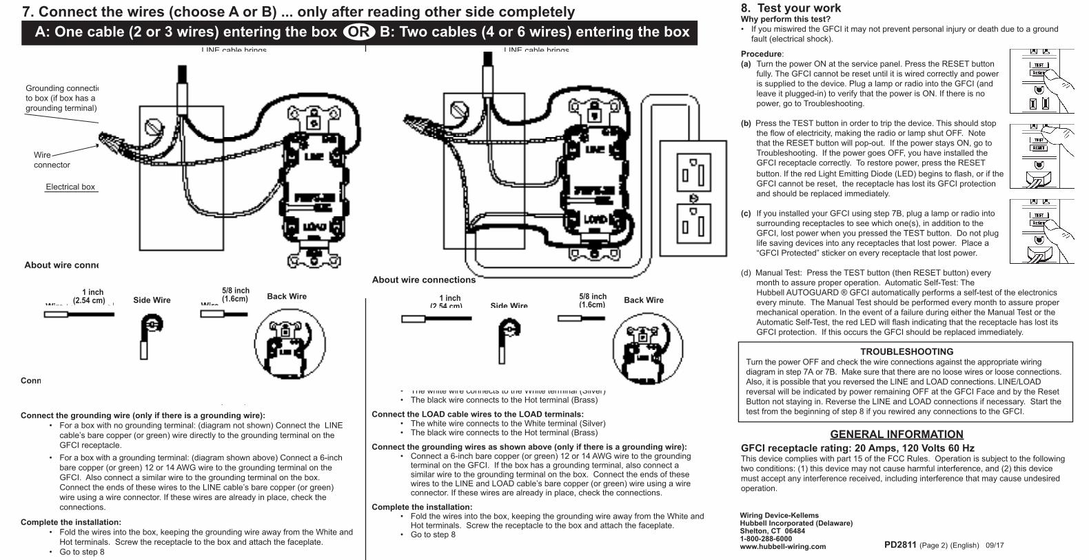
8. Test your workWhy perform this test?• If you miswired the GFCI it may not prevent personal injury or death due to a ground
fault (electrical shock).
Procedure:(a) Turn the power ON at the service panel. Press the RESET button
fully. The GFCI cannot be reset until it is wired correctly and power is supplied to the device. Plug a lamp or radio into the GFCI (and leave it plugged-in) to verify that the power is ON. If there is no power, go to Troubleshooting.
(b) Press the TEST button in order to trip the device. This should stop
the flow of electricity, making the radio or lamp shut OFF. Note that the RESET button will pop-out. If the power stays ON, go to Troubleshooting. If the power goes OFF, you have installed the GFCI receptacle correctly. To restore power, press the RESET button. If the red Light Emitting Diode (LED) begins to flash, or if the GFCI cannot be reset, the receptacle has lost its GFCI protection and should be replaced immediately.
(c) If you installed your GFCI using step 7B, plug a lamp or radio into surrounding receptacles to see which one(s), in addition to the GFCI, lost power when you pressed the TEST button. Do not plug life saving devices into any receptacles that lost power. Place a “GFCI Protected” sticker on every receptacle that lost power.
(d) Manual Test: Press the TEST button (then RESET button) every month to assure proper operation. Automatic Self-Test: The Hubbell AUTOGUARD ® GFCI automatically performs a self-test of the electronics every minute. The Manual Test should be performed every month to assure proper mechanical operation. In the event of a failure during either the Manual Test or the Automatic Self-Test, the red LED will flash indicating that the receptacle has lost its GFCI protection. If this occurs the GFCI should be replaced immediately.
TROUBLESHOOTINGTurn the power OFF and check the wire connections against the appropriate wiring diagram in step 7A or 7B. Make sure that there are no loose wires or loose connections. Also, it is possible that you reversed the LINE and LOAD connections. LINE/LOAD reversal will be indicated by power remaining OFF at the GFCI Face and by the Reset Button not staying in. Reverse the LINE and LOAD connections if necessary. Start the test from the beginning of step 8 if you rewired any connections to the GFCI.
PD2811 (Page 2) (English) 09/17
GENERAL INFORMATIONGFCI receptacle rating: 20 Amps, 120 Volts 60 HzThis device complies with part 15 of the FCC Rules. Operation is subject to the following two conditions: (1) this device may not cause harmful interference, and (2) this device must accept any interference received, including interference that may cause undesired operation.
Wiring Device-KellemsHubbell Incorporated (Delaware)Shelton, CT 064841-800-288-6000www.hubbell-wiring.com
A: One cable (2 or 3 wires) entering the box OR B: Two cables (4 or 6 wires) entering the box7. Connect the wires (choose A or B) ... only after reading other side completely
OR
Connect the LINE cable wires to the LINE terminals: • The white wire connects to the White terminal (Silver) • The black wire connects to the Hot terminal (Brass)
Connect the grounding wire (only if there is a grounding wire): • For a box with no grounding terminal: (diagram not shown) Connect the LINE
cable’s bare copper (or green) wire directly to the grounding terminal on the GFCI receptacle.
• For a box with a grounding terminal: (diagram shown above) Connect a 6-inch bare copper (or green) 12 or 14 AWG wire to the grounding terminal on the GFCI. Also connect a similar wire to the grounding terminal on the box. Connect the ends of these wires to the LINE cable’s bare copper (or green) wire using a wire connector. If these wires are already in place, check the connections.
Complete the installation: • Fold the wires into the box, keeping the grounding wire away from the White and
Hot terminals. Screw the receptacle to the box and attach the faceplate. • Go to step 8
Connect the LINE cable wires to the LINE terminals: • The white wire connects to the White terminal (Silver) • The black wire connects to the Hot terminal (Brass)
Connect the LOAD cable wires to the LOAD terminals: • The white wire connects to the White terminal (Silver) • The black wire connects to the Hot terminal (Brass)
Connect the grounding wires as shown above (only if there is a grounding wire): • Connect a 6-inch bare copper (or green) 12 or 14 AWG wire to the grounding
terminal on the GFCI. If the box has a grounding terminal, also connect a similar wire to the grounding terminal on the box. Connect the ends of these wires to the LINE and LOAD cable’s bare copper (or green) wire using a wire connector. If these wires are already in place, check the connections.
Complete the installation: • Fold the wires into the box, keeping the grounding wire away from the White and
Hot terminals. Screw the receptacle to the box and attach the faceplate. • Go to step 8
LOAD cable feeds power to other receptacle(s)
Electrical box
Wireconnector
LINE cable brings power to the GFCI
Grounding connection to box (if box has a grounding terminal)
Black
Black
White
White
Green
GreenGreenGreen
About wire connections
Green
Black
White
Green
Grounding connection to box (if box has a grounding terminal)
Electrical box
Wireconnector
LINE cable brings power to the GFCI
Green
Back Wire Back WireSide Wire
Clockwise, 2/3 of the way around the screw
Wire1 inch
(2.54 cm) Wire
5/8 inch (1.6cm)
Insert wire to the bottom of hole and tighten down screw
About wire connections
Side Wire
Clockwise, 2/3 of the way around the screw
Wire1 inch
(2.54 cm) Wire
5/8 inch (1.6cm)
Insert wire to the bottom of hole and tighten down screw

4. LÍNEA versus CARGAUn cable consiste en 2 ó 3 conductores.
Cable de LÍNEA (LINE)Transporta la energía desde el panel de distribución (panel de disyuntores o caja de fusibles) hasta el receptáculo GFCI. Si existe sólo un cable en la caja, este cable es el cable de línea. Este cable debería conectarse sólo a los bornes de LÍNEA del receptáculo GFCI.
Cable de CARGA (LOAD):Transporta energía desde el GFCI hasta otro receptáculo del circuito. Este cable debería conectarse sólo a los bornes de CARGA (LOAD) del GFCI.
PRECAUCIÓN 2. Las particularidades del GFCI
Cable Conductores
Instalación y verificación de
receptáculo GFCI
Leer todas las instrucciones antes
de instalar
PD2811 (Page 5) (Español) 09/17
!• Paraevitarchoqueseléctricoso
electrocución,siempreinterrumpirlacorrienteenelpaneldedistribuciónantesdetrabajarenelcableado.
• Utilizarestereceptáculo coninterruptordeescapeatierra(GFCI)conconductoresdecobreorecubiertosconcobre.Noutilizarloconconductoresdealuminio.
• NoinstalaresteGFCIencircuitosquealimentenequiposdemantenimientodevidapues,encasodedispararse,apagarátalesequipos.
•Paralainstalaciónenlugareshúmedosomojados,elreceptáculoconinterruptordecircuitoporfallaatierradebemarcarsecomoresistentealaintemperie(WRoRI).
• Parainstalacionesenlugareshúmedos,protegerelGFCIconunacubiertaimpermeableparamantenersecostantoalreceptáculocomoacualquierclavijaenchufada.
• Debeinstalarsedeacuerdoconloscódigoseléctricosnacionalesylocales.
1.QuéesunreceptáculoGFCI?Un receptáculo (GFCI) es diferente a un receptáculo convencional. En caso de falla por escape a tierra, el receptáculo GFCI se disparará interrumpiendo rápidamente la circulación de electricidad, evitando así ocasionar lesiones graves.
DefinicióndefallaporescapeatierraEn lugar de seguir su recorrido normal, la electricidad pasará a través del cuerpo de la persona para llegar a la tierra. Por ejemplo, un artefacto defectuoso puede causar una falla por escape a tierra.Un receptáculo (GFCI) NO protege contra sobrecargas, cortocircuitos o choques eléctricos. Por ejemplo, Ud. puede recibir un choque eléctrico si toca conductores desnudos estando parado sobre una superficie no conductora, tal como un piso de madera.
3.DeberíainstalarloUd.mismo?
Instalar un receptáculo GFCI puede resultar más complicado que instalar un receptáculo convencional.
Asegúrese que Ud.:
• Comprende los principios y técnicas básicas de cableado
• Puede entender diagramas de cableado
• Tiene experiencia en cableado de circuitos
• Está preparado para tomarse algunos minutos a fin de asegurarse que ha cableado correctamente el receptáculo GFCI
5.InterrumpirlacorrienteEnchufar un artefacto eléctrico, tal como una lámpara o radio, al receptáculo en el cual Ud. está trabajando. Encienda la lámpara o radio. Diríjase luego al panel de distribución. Localice el disyuntor o fusible que protege ese receptáculo. Lleve el disyuntor a la posición OFF o retire completamente el fusible. La lámpara o radio debería apagarse.A continuación, enchufe y encienda la lámpara
o radio en la otra salida del receptáculo, a fin de asegurarse que la corriente está interrumpida en ambas salidas. Si la corriente no está interrumpida, no continúe con el trabajo y llame a un electricista para que termine la instalación.
6.IdentificacióndeloscablesyconductoresImportante:No instalar el receptáculo GFCI en una caja eléctrica que contenga: (a) más de 4 conduc-tores (sin incluir los conductores de tierra) o (b) cables con más de 2 conductores (sin incluir los conductores de tierra), comuníquese con un electricista calificado si se cumple algu-no de los casos (a) ó (b).
Si Ud. está reemplazando un receptáculo viejo, retírelo de la caja eléctrica sin desconectarlo de los cables.
• Si ve un solo cable (2-3 conductores), se trata del cable de LÍNEA. El receptáculo probablemente esté en la posición C (ver el diagrama de la derecha). Retirar el receptáculo y continúe con el paso 7A.
• Si ve dos cables (4-6 conductores), el receptáculo probablemente esté en la posición A o B (ver el diagrama de la derecha). Siga los pasos del procedimiento de la derecha.
Procedimiento:cajacondoscables(4-6conductores)(a) Separe del receptáculo los conductores
blanco y vivo correspondientes a uno de los cables, y coloque sobre cada uno de ellos un conector de cable. Asegúrese que corresponden al mismo cable.
(b) Reinstale el receptáculo en la caja, colo-que la tapa y luego, restablezca la corrien-te en el panel de distribución.
(c) Determine si la corriente llega al receptá-culo. Si es así, los conductores cubiertos con conectores de cable serán los conduc-tores de CARGA (LOAD). De lo contrario, corresponderán a los conductores de LÍNEA.
(d) Interrumpa la corriente en el panel de distribución, rotule los conductores de LÍNEA y CARGA (LOAD), y retire entonces el receptáculo.
(e) Continúe con el paso 7B.
Ubicaciónenelcircuito:La ubicación del GFCI en el circuito determinará que proteja o no a otros receptáculos en el circuito.Colocando el receptáculo GFCI en
la posición A, se protegerá también a los receptáculos B y C del lado de la carga. Por otra parte, si se coloca el GFCI en la posición C, no se protegerá a los receptáculos A o B. Recuerde que los receptáculos A, B y C pueden estar en diferentes habitaciones.
cargacarga
línea
Panel de
distribución
A B Clínea línea
Ejemplodecircuito
®
Wiring Systems
DORSOFRENTEBorne de tierra (verde): Conexión para conductor de cobre verdo o desnudo
LÍNEA Borne blanco (plateado): Conexión para el conductor blanco del cable de LÍNEA
CARGA Borne blanco (plateado): Conexión para el conductor blanco del cable de CARGA
Color de los tornillos de borne: Verde = borne de tierraPlateado = bornes blancosLatón = bornes vivos
LÍNEABorne vivo (latón):Conexión para el conductor negro del cable de LÍNEA
CARGABorne vivo (latón):Conexión para el conductor negro del cable de CARGA
Dispositivo
Receptáculo
Botón TEST Ver paso 8
Botón RESET Ver paso 8
Brida de fijación
Receptáculo
DIODO LUMÍNICOROJO: indicación de final de la vida útil (destellante)

8.PongaapruebasutrabajoPorquéhacerestaprueba?• Si Ud. cometió un error en el cableado del receptáculo GFCI, éste probablemente no evitará
las lesiones personales o muerte debidas a una falla por escape a tierra (choque eléctrico).
Procedimiento:(a) Conecte la corriente en el panel de distribución. Pulse a fondo el botón «RESET». El GFCI
no puede reactivarse mientras no esté correctamente cableado y energizado.Enchufe una lámpara o radio al receptáculo GFCI (y déjelo enchufado) para verificar que la corriente está conectada. Si no hay corriente, continúe en la sección: Reparación de averías.
(b) Pulse el botón «TEST» para disparar el dispositivo. Esto debería interrumpir la circulación de corriente, haciendo apagar la lámpara o radio. Observe que salte el botón «RESET». Si la corriente se mantiene, continúe en la sección: Reparación de averías. Si la corriente se interrumpe, Ud. habrá instalado correctamente el receptáculo GFCI. Para restablecer la corriente, pulse el botón «RESET». Cuando el diodo luminoso (LED) rojo emite destellos, o si el ICFT no puede reiniciarse el receptáculo ha quedado sin protección contra escape a tierra y debería ser reemplazado inmediatamente.
(c) Si Ud. instaló su receptáculo GFCI siguiendo el paso 7B, enchufe una lámpara o radio en los receptáculos cercanos para ver cuál/es, además del tomacorriente GFCI, interrumpió la corriente cuando Ud. pulsó el botón «TEST». No conecte dispositivos para salvar vidas en los receptáculos cuya corriente está interrumpida. Coloque una etiqueta de «receptáculo protegido» en cada receptáculo cuya corriente está interrumpida.
d) Prueba manual: Pesionar el botón TEST (y luego el botón RESET) una vez al mes para asegurar el buen funcionamiento. Prueba automática: El interruptor de escape a tierra (GFCI) AUTOGUARD ® de Hubbell realiza una prueba de sus circuitos electrónicos una vez por minuto. La prueba manuel debiera realizarse una vez mes para asegurar el buen funcionamiento mecánico. En caso de falla durante la prueba manual o la prueba automática, el diodo lumínico (LED) rojo destellará indicando que el receptáculo ha perdido la protección contra escape a tierra. Si esto sucede, el interruptor de escape a tierra (GFCI) deberá ser reemplazado inmediatamente.
PD2811 (Page 6) (Español) 09/17
INFORMACIÓN GENERALCaracterísticas del GFCI:20A,V~120,60Hz
7.Conectarlosconductores(elegirAoB)...LeertodaslasinstruccionesantesdeconectarA:Unsolocable(2ó3conductores)enlacajaO B:Doscables(4ó6conductores)enlacaja
WiringDevice-KellemsHubbellIncorporated(Delaware)Shelton,CT064841-800-288-6000www.hubbell-wiring.com
SOLUCIÓN DE PROBLEMASInterrumpir la corriente y comprobar que las conexiones de los cables coincidan con el diagrama de cableado apropiado según el paso 7A ó 7B. Asegurarse de que no hayan hilos sueltos o contactos flojos. También, es posible haber invertido las conexiones de LÍNEA (LINE) y CARGA (LOAD). La inversión de LÍNEA / CARGA quedará en evidencia si no hay corriente en el receptáculo del GFCI y si el botón “Reset” no permanece introducido. Invertir las conexiones de LÍNEA y CARGA si fuera ne-cesario. Comenzar la prueba desde el principio del paso 8 si debe volver a cablear cualquier conexión al GFCI.
HUBBELL DE MEXICO garantiza este producto, de estar libre de de-fectos en materiales y mano de obra por un año a partir de su compra. Hubbell reparará o reemplazará ei artículo a su juicio en un plazo de 60 días. Esta garantía no cubre desgastes por uso normai o daños ocasionados por accidente, mal uso, abuso o neqligencia. El vendedor no otorga otras garantias y excluye expresarnente daños incidentales o consecuenciales inherentes a su uso.
HUBBELL DE MEXlCO, S.A.de C.V.Av.InsurgentesSur#1228Piso8Tel.:(55)9151-9999Col.TlacoquemecatldelValleMéxico,03200D.F.
Este dispositivo cumple con la parte 15 de los reglamentos del FCC. Su funcionamien-to está sujeto a las dos condiciones siguientes: (1) este dispositivo no puede causar la interferencia perjudicial, y (2) este dispositivo debe aceptar cualquier interferencia recibida, incluyendo la interferencia que puede causar la operación indeseada.
Enelsentidodelasagujasdelreloj,alrededordeltornillo2/3devuelta
Enelsentidodelasagujasdelreloj,alrededordeltornillo2/3devuelta
Hilo(2.54cm)1inch Hilo
(1.6cm)5/8inch
Insertarelconductorenelfondodelagujeroyapretareltornillo
Conexionesdelosconductores
HiloHilo(2.54cm)
1inch
(1.6cm)5/8inch
Insertarelconductorenelfondodelagujeroyapretareltornillo
Cableadolateral CableadoPosterior
Cableadolateral CableadoPosterior
ConectarlosconductoresdelcabledeLÍNEAalosbornesdeLÍNEA.• El conductor blanco se conecta al borne blanco (plata)• El conductor negro se conecta al borne vivo (HOT) (latón)ConectarlosconductoresdelcabledeCARGAalosbornesdeCARGA:• El conductor blanco se conecta al borne blanco (plata)• El conductor negro se conecta al borne vivo (HOT) (latón)Conectarlosconductoresdetierracomosemuestraarriba(sólosihayconductordetierra)• Conectar un conductor de cobre desnudo (o verde) de calibre 12 ó 14 AWG y 15 cm de
largo, al borne de tierra del GFCI. Si la caja tiene borne de tierra, conectar también un conductor similar al borne de tierra de la caja. Conectar los extremos de estos conductores al conductor de cobre desnudo (o verde) del cable de LÍNEA y CARGA usando un conector roscado.
Terminarlainstalación:• Arrollar los cables dentro de la caja, manteniendo el conductor de tierra alejado de los
bornes blanco y vivo. Atornillar el receptáculo a la caja y colocar la tapa.• Continuar con el paso 8.
ConectarlosconductoresdelcabledeLÍNEAalosbornesdeLÍNEA.• El conductor blanco se conecta al borne blanco (plata)• El conductor negro se conecta al borne vivo (HOT) (latón)
Conectarelconductordetierra(sólosihayconductordetierra)• Para una caja sin borne de tierra (no se muestra el diagrama), conectar el conductor de
cobre desnudo (o verde) del cable de LÍNEA directamente al borne de tierra del receptáculo GFCI.
• Para una caja con borne de tierra (diagrama de arriba), conectar un conductor de cobre desnudo (o verde) de calibre 12 ó 14 AWG y 15 cm de largo, al borne de tierra del receptáculo GFCI. Conectar también un conductor similar al borne de tierra de la caja. Conectar los extremos de estos conductores al conductor de cobre desnudo (o verde) del cable de LíNEA usando un conector roscado. Si estos conductores ya están instalados, verificar las conexiones.
Terminarlainstalación• Arrollar los cables dentro de la caja, manteniendo el conductor de tierra alejado de los
bornes blanco y vivo (HOT). Atornillar el receptáculo a la caja y colocar la tapa.• Continuar con el paso 8.
Conexionesdelosconductores
Conexión à tierra de la caja (si existe un borne de tierra en la caja)
Caja eléctrica
Negro
Verde
Blanco
Connector roscado
Cable de LÍNEA - Transporta la energía hasta el GFCI
Verde
Verde
Cable de LÍNEA - Transporta la energía hasta el GFCI
Conexión à tierra de la caja (si existe un borne de tierra en la caja)
Connector roscador
Cajaeléctrica
Verde
Verde
Verde
Negro
Verde
Blanco
Blanco
Negro
Cable de CARGA Transporta la energia hast oros receptàculos

1. Qu’est-ce qu’un IDALT?La prise IDALT diffère des prises conven-tionnelles. En présence d’un défaut à la terre, l’IDALT déclenche et arrête rapide-ment le courant en vue de prévenir les blessures graves.
Définition du défaut à la terre :Au lieu de suivre son cheminement sécuri-taire normal, l’électricité passe par le corps de la personne pour se rendre à la terre. À titre d’exemple, un appareil défectueux peut causer un défaut à la terre.
La prise IDALT ne protège pas contre les surcharges de circuit, les courts-circuits ou les chocs électriques. Ainsi par exemple, vous risquez un choc électrique si vous touchez des fils nus tout en étant debout sur une surface non conductrice telle qu’un plancher de bois.
5. Mise HORS TENSIONBranchez un appareil électrique, tel qu’une lampe ou une radio, dans la prise sur laquelle vous travaillez. Allumez la lampe ou la radio. Rendez-vous au panneau de service et trouvez le disjoncteur ou le fusible qui protège la prise. Placez le disjoncteur en position «OFF» ou enlevez complètement le fusible. La lampe ou la radio devrait s’éteindre.
Ensuite, branchez et allumez la lampe ou la radio dans l’autre sortie de la prise pour vous assurer que le courant est coupé aux deux sorties. Si le courant n’est pas coupé, arrêtez immédiatement le travail et faites appel un électricien pour compléter le montage.
Important :Ne pas monter la prise IDALT dans une boîte électrique comprenant (a) plus de 4 fils (sans inclure les fils de mise à la terre) ou (b) des câbles de plus de deux fils (sans inclure le fil de mise à la terre). Si c’est le cas (a) ou (b), faire appel à un électricien qualifié.
Pour remplacer une vieille prise, enlever cette dernière de la boîte électrique sans déconnecter les fils.
• Si vous voyez un seul câble (de 2 à 3 fils), il s’agit du câble d’ALIMENTATION. La prise est probablement en position C (voir schéma à droite). Enlevez la prise et passez à l’étape 7A..
• Si vous voyez deux câbles (de 4 à 6 fils), suivez les directives données à droite. La prise est probablement en position A ou B (voir schéma à droite).
2. Les particularités d’un IDALT
Procédure : boîte à deux câbles (de 4 à 6 fils)(a) Détacher le fil blanc et le fil noir du câble
de la prise et recouvrez chacun des fils d’un raccord à torsader. S’assurer qu’ils appartiennent au même câble.
(b) Replacer la prise dans la boîte électrique, fixer la plaque de face et ensuite rétablir le courant au panneau de service.
(c) Déterminer si le courant passe dans la prise. Dans l’affirmative, les fils recouverts d’un raccord à torsader sont les fils de CHARGE. Dans le cas contraire, les fils recouverts d’un raccord sont les fils d’ALIMENTATION.
(d) Couper le circuit d’alimentation au panneau de service, étiqueter les fils d’ALIMENTATION et de CHARGE et ensuite enlever la prise.
(e) Passer à l’étape 7B.
• Pour éviter les chocs électriques graves, il faut toujours COUPER la source d’alimentation au panneau de service avant d’entreprendre le câblage.
• Utiliser du fil de cuivre ou du fil cuivré avec la prise IDALT. Ne jamais utiliser du fil d’aluminium.
• Ne pas monter la prise IDALT sur un circuit alimentant des appareils de survie parce que le déclenchement de l’IDALT provoquera l’arrêt de tout le matériel.
• Pour l'installation dans des endroits humides ou mouillés, la prise de courant de disjoncteur différentiel doit être classée et marquée résistante aux intempéries (WR).
• Pour le montage dans des endroits mouillés, il faut protéger la prise IDALT à l’aide d’un couvercle à l’épreuve des intempéries qui maintiendra la prise et les fiches éventuelles au sec.
• Ce produit doit être monté conformément aux directives des codes de l’électricité nationaux et locaux.
ATTENTION
3. Devriez-vous la monter vous-même?
Le montage d’une prise IDALT peut s’avérer plus compliqué que celui d’une prise conventionnelle.
Vous devez vous assurer que :
• Vous comprenez les principes de base et les techniques de câblage,
• Vous êtes capable d’interpréter les schémas de câblage.
• Vous avez l’expérience nécessaire en matière de câblage de circuit
• Vous êtes prêt à prendre quelques minutes pour tester le travail pour vous assurer que vous avez câblé correctement la prise IDALT.
4. ALIMENTATION et CHARGEUn câble comprend 2 ou 3 fils.
Câble d’ALIMENTATION :À partir du panneau de service (panneau de disjoncteur ou boîte de fusibles), il alimente la prise IDALT en énergie. S’il y a seulement un câble qui entre dans la boîte électrique, c’est le câble d’ALIMENTATION. Ce câble doit être connecté uniquement aux bornes d’ALIMENTATION (LINE) de la prise IDALT.
Câble de CHARGE :Il transporte l’énergie de la prise IDALT à une autre prise sur le circuit. Ce câble doit être connecté uniquement aux bornes de CHARGE (LOAD) de la prise IDALT.
6. Identification des câbles et des filsEmplacement dans le circuitLa place de la prise IDALT dans le circuit détermine la protection éventuelle des au-tres prises du circuit.
Lorsque l’IDALT est placé en position A, il assure la protection des prises «côté charge» B et C. D’autre part, placé en position C, l’IDALT ne protège pas les prises A et B. N’oubliez pas que les prises A, B et C peuvent se trouver dans des pièces différentes.
Exemple de circuit
Directives de montage
et de vérification des
prises IDALTLire ce dépliant entièrement
avant d'entreprendre le montage
PD2811 (Page 3) (Français) 09/17
!
Câble Fils
®
Wiring Systems
Panneau de
service
alimentation alimentationalimentation
A B C
CHaRGe CHaRGe
CHARGEBorne blanche (argentée) Connexion pour le fil blanc du câble de CHARGE
Dispositif
Prise
Bouton TEST étape 8
Bouton RESET étape 8
Prise
Bride de fixation
Couleur des vis de bornesVert = Borne de MALTArgenté = Bornes blanchesLaiton = Bornes vivantes
VIVANTBorne vivante (laiton)Connexion pour le fil noir du câble d'ALIMENTATION
CHARGEBorne vivante (laiton) Connexion pour le fil noir du câble de CHARGE
Borne de mise à la terre (vert)Connexion pour fil de cuivre nu ou vert
VIVANTBorne blanche (argentée)Connexion pour le fil blanc du câble d'ALIMENTATION
VUE DE FACE VUE ARRIÈRE
DIODE ROUGEfin de vie utile (clignotement)

RENSEIGNEMENTS GÉNÉRAUX
Valeurs assignées20 ampères
120 volts60 Hz
PD2811 (Page 4) (Français) 09/17
Wiring Device-KellemsHubbell Incorporated (Delaware)Shelton, CT 064841-800-288-6000www.hubbell-wiring.com
DÉPANNAGECouper l’alimentation électrique (OFF) et vérifier les connexions en consultant le schéma de câblage approprié conformément aux étapes 7A ou 7B. S’assurer que les fils et les connexions sont bien serrés. De plus, il est possible que les connexions ligne (LINE) et charge (LOAD) aient été inversées. L’inver-sion des connexions ligne et charge (LINE/LOAD) se manifestera par l’absence de courant au niveau de l’IDALT et par le bouton RESET qui refusera de rester enfoncé. Inverser les connexions ligne (LINE) et charge (LOAD) au besoin. Reprendre l’essai à partir de l’étape 8 si les connexions de l’IDALT ont été modifiées.
FICHE DE VÉRIFICATION MENSUELLE DE L'IDALT ANNÉE Jan Fév Mar Avr Mai Juin Juil Août Sep Oct Nov Déc
AVIS - Apposer dans un endroit visible afin de rappeler à l'utilisateur de faire les vérificaitons mensuelles
Cet dispositif est confrome à la Partie 15 de la réglementation du FCC. Son utilisation est assujettie aux conditions suivantes: (1) ce dispositif ne puet causer un brouillage préjudi-ciable, et (2) ce dispositif doit réagir aux interférences émises y compris celles qui sont susceptibles de provo-quer un fonctionnement intempestif.
Verte
Verte
À propos des connexions
Dans le sens horaire, aux 2/3 du pourtour de la vis
Fil
Câblage arrière
(2.54 cm) 1 inch
Câblage latéral(1.6cm) 5/8 inch
FilÀ propos des connexions
Fil(2.54 cm) 1 inch (1.6cm)
5/8 inch
Câblage arrièreCâblage latéral
Dans le sens horaire, aux 2/3 du pourtour de la vis
Fil
Insérer le conducteurau fond du trou etserrer la vis
Insérer le conducteurau fond du trou etserrer la vis
Connecter les fils du câble d’ALIMENTATION aux bornes de l’ALIMENTATION (LINE) • Le fil blanc doit être connecté à la borne blanche (argentée).• Le fil noir doit être connecté à la borne vivante (laiton).
Connecter le fil de mise à la terre (le cas échéant seulement) :• Pour une boîte sans borne de mise à la terre : (pas de schéma proposé).
Connecter le fil de cuivre nu (ou le fil vert) du câble d’ALIMENTATION di-rectement à la borne de mise à la terre de la prise IDALT.
• Pour une boîte avec borne de mise à la terre : (voir schéma ci-dessus). Con-necter un fil de cuivre nu (ou un fil vert) de 15 cm, de calibre 12 ou 14 AWG, à la borne de mise à la terre de la prise IDALT. Connecter également un fil semblable à la borne de mise à la terre de la boîte. À l’aide d’un raccord à torsader, connecter les extrémités de ces fils au fil de cuivre nu (ou fil vert) du câble d’ALIMENTATION.
Compléter le montage :• Replier les fils dans la boîte en s’assurant de maintenir les fils de mise à la
terre éloignés des bornes blanche et vivante. Visser la prise sur la boîte et fixer la plaque de face.
• Passer à l’étape 8.
Connecter les fils du câble d’ALIMENTATION aux bornes de l’ALIMENTATION (LINE)• Le fil blanc doit être connecté à la borne blanche (argentée).• Le fil noir doit être connecté à la borne vivante (laiton).Connecter les fils du câble de CHARGE aux bornes de la CHARGE (LOAD)• Le fil blanc doit être connecté à la borne blanche (argentée).• Le fil noir doit être connecté à la borne vivante (laiton).Connecter les fils de mise à la terre (le cas échéant seulement)• Connecter un fil de cuivre nu (ou un fil vert) de 15 cm, de calibre 12 ou 14 AWG
à la borne de mise à la terre de la prise IDALT. Si la boîte est munie d’une borne de mise à la terre, connecter un fil semblable à la borne de mise à la terre de la boîte. À l’aide d’un raccord à torsader, connecter les extrémités de ces fils au fil de cuivre nu (ou fil vert) des câbles d’ALIMENTATION et de CHARGE.
Compléter le montage :• Replier les fils dans la boîte en s’assurant de maintenir les fils de mise à la terre
éloignés des bornes blanche et vivante. Visser la prise sur la boîte et fixer la plaque de face.
• Passer à l’étape 8.
7. Connecter les fils (choisir A ou B)... seulement après avoir lu attentivement la page précédente A : un seul câble (de 2 ou 3 fils) entrant dans la boîte OU B : deux câbles ( de 4 ou 6 fils) entrant dans la boîteOU
Connexion de mise à la terre de la boîte (si la boîte a une borne de mise à la terre)
Boîteélectrique
Noir
Verte
Blanc
Raccord à torsader
Le câble d'ALIMENTATION fournit l'énergie à la prise IDALT
Le câble d'ALIMENTATION fournit l'énergie à la prise IDALT
Connexion de mise à la terre de la boîte (si la boîte a une borne de mise à la terre)
Raccord à torsader
Boîteélectrique
Verte
Verte
Verte
Noir
Verte
Blanc
NoirLe câble de CHARGE alimente les autres prises
8. Tester le travailPour quelle raison faut-il effectuer ce test?• Si l’IDALT a été mal câblé, il ne pourra pas protéger contre les blessures
personnelles ou le décès causés par un défaut à la terre (c’est-à-dire un choc électrique).
Procédure
(a) Mettre le circuit sous tension au panneau de service. Enfoncer le bouton de rappel «RESET». Le bouton de rappel ne peut fonctionner jusqu’à ce que l’IDALT soit câblé correctement et sous tension.Brancher une lampe ou une radio dans la prise IDALT (et l’y laisser branchée) en vue de vérifier si le circuit est sous tension. S’il n’y a pas de tension, passer à la rubrique «Diagnostic des anomalies».
(b) Appuyer sur le bouton «TEST» pour déclencher le dispositif. Ceci devrait arrêter le courant et éteindre la lampe ou la radio. Remarquez que le bouton «RESET» devrait surgir. Si l’appareil est toujours sous tension, passer à la rubrique «Diagnostic des anomalies». Si l’appareil n’est plus sous tension, c’est que la prise IDALT a été montée correctement. Pour restaurer la tension, appuyer sur le bouton «RESET».
Lorsque la diode électroluminescente (DEL) rouge se met à clignoter, ou si le DDFT ne peut être réarmé a prise n’est plus protégée contre les défauts à la terre et doit être remplacée immédiatement.
(c) Si la prise IDALT a été montée selon les directives 7B, brancher la lampe ou la radio dans les prises environnantes afin de déterminer celles qui, en plus de la prise IDALT, ont été mises hors tension lorsqu’on a appuyé sur le bouton «TEST». Ne pas brancher d’appareils de survie dans des prises qui ont été mises hors tension. Placer un autocollant «Protégé par IDALT» sur toutes les prises qui ont été mises hors tension.
(d) Essai manuel : Appuyer sur le bouton TEST (puis RESET) chaque mois pour vérif er le fonctionnement.
Essai automatique : L'IDALT AUTOGUARD ® de Hubbell vérifie automatiquement le circuit électronique toutes les minutes. II importe de procéder à un essai manuel tous les mois pour vérifier le fonctionnement mécanique. En cas défaillance pendant un essai manuel ou automatique, la diode rouge clignote pour indiquer que la prise n'est plus protégée contre les défauts à la terre. Si cela se produit, remplacer L'IDALT immédiatement.
1.5
1 1
1 1
Blanc