Embed Size (px)
Citation preview
Building mySAP.com™ Ready Networks
Solutions Brief
IntroductionEnterprise systems are helping companies achieve their business objectives by streamlining and
integrating their core business processes, such as manufacturing, human resources, and finance.
Very often the decision to implement an enterprise solution is a strategic decision costing
millions of dollars to deploy and maintain.These enterprise solutions are the business engines
that drive a modern corporation’s information flow. Key to making these applications run
successfully is the network.These applications are not only business-centric to companies, but
also network-centric. By building a network that meets the stringent demands of the
enterprise solution, you will help ensure the initial and on-going success of these mission-
critical systems.These demands include high availability, scalability and also the ability to
protect enterprise applications from other less time-critical traffic, such as Web browsing,
e-mail, and file transfers.This requires an understanding of the application, its architecture and
its expectations of the network.
This solutions guide provides an overview of the mySAP.com computing environment, and
provides guidelines with respect to designing an appropriate network to support mySAP.com
solutions.
SAP is the world’s leading provider of business application software. SAP software has been
installed in more than 12,000 companies worldwide, and has a leading market share.Through
mySAP.com™, SAP is delivering business solutions for optimizing inter-enterprise collaboration
for one-step business in the Internet economy.
Through technology, expertise and partnership Cisco is committed to helping customers
deploy end-to-end networking solutions that support and enhance their business-critical
mySAP.com solution environments. Cisco’s technology partnership with SAP is aimed at
empowering our joint customers to take full advantage of the Internet economy.
Building mySAP.com Ready Networks 1
2 mySAP.com - Overview
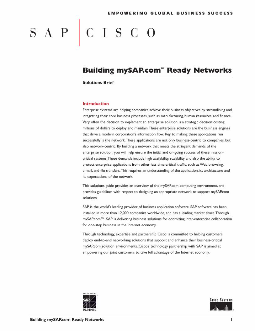
The mySAP.com solutions environment comprises multiple
integrated applications, providing a modular flexible and
scalable system that meets needs across most business
sectors.The core integrated applications can be categorized
under financials, logistics and human resource management.
Each of these, in turn consist of multiple applications.
For instance, logistics includes general logistics, material
management, plant maintenance and production planning,
among others.Additionally there are cross-application
functionality which takes advantage of the data stored by
multiple applications.These applications include business
workflow, business warehouse, office tools like e-mail and
word processing; and archiving utilities.
SAP applications are integrated by means of the SAP Basis
System which provides foundation services. SAP also offers
Industry Solution packages targeted to 17 specialized vertical
industries such as banking, insurance, healthcare, retail, oil &
gas, high tech, automotive, utilities among others.
SAP products and services integrate an organization from
financials, human resources and manufacturing to sales,
distribution and customer relationship management.This
integration enables companies to optimize supply chains,
strengthen customer relationships, and leverage business
intelligence to make more accurate management decisions.
Building mySAP.com Ready Networks 2
IndustrySolutions
Core SAP™Applications
Auto
mot
ive
Cons
truct
ion
Chem
icals
Oil a
nd G
as
Healt
h Ca
re
Aero
spac
e an
dDe
fens
e
High
Tech
Utilit
ies
Telec
om
Reta
il
Publ
ic Se
ctor
SAP Basis System
Financials SAP LogisticsHuman
ResourcesBusiness
InformationWarehouse
SAP SAP
Source: SAP AG
Figure 1: Basic Components of mySAP.com
Employee SelfServices
Supply ChainManagement
XML-enabling
Internet ApplicationComponents
Enterprise ResourcePlanning
Inter-EnterpriseCooperation
e-CommunityCollaboration
Continuous Knowledge Transfer
BusinessIntelligence
Workplaces
94 97 99
BusinessScenarios
PartneringPlatform
Portals
Outs
ourc
ing
IndustrySolutions
Business FrameworkTechnology, BAPIs
e-Commerce
Marketplaces
Customer RelationshipManagement
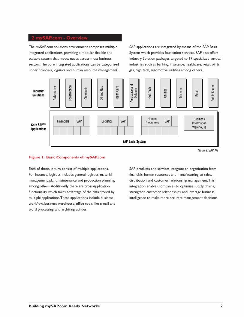
Source: SAP AGFigure 2: mySAP.com Roadmap
2.1 SAP ArchitectureSAP solution architecture is a 3-tier client/server
architecture. In this environment, the presentation/client, the
application, and the database can each reside on separate
computers and servers for greater scalability, improved
operations, and support for multiple platforms.The 3-tier
architecture offers increased performance and reduced
network traffic, since all of the database inquiries are kept
local to the data-center, and only presentation traffic flows
across the enterprise-wide network. Each tier has very
distinct functions.
■ The first tier consists of a database management system,
which stores the data upon which the SAP applications
operate.The specific databases employed are to a large
extent independent of the SAP solution, so that the
customer and the system integrator are free to determine
whether to use an Oracle, Microsoft, Informix, IBM or
other database system.All the data associated with a single
SAP solution or “instance” is located in this central
database system.
■ The second tier application systems are the heart of the
SAP solution.This tier consists of the application logic,
responsible for processing client transactions, print jobs,
running reports, coordinating access to the database and
interfacing with other applications.The applications
translate user transaction or report requests into the
appropriate SQL queries to the databases, and process
the query results into the information that the client
has asked for.
■ Today, the third tier mainly consists of a thin client
software application, named SAPGUI, typically running on
Microsoft Windows clients, although other platforms are
also supported.The user is presented with standard forms
or screens, which need to be filled in order to carry out a
specific transaction, such as order/entry, accounting or
production planning.These screens are then sent to an
application server, which replies with the next screen and
appropriate data. Each user-initiated transaction such as an
order entry, will typically require multiple dialog screen
interactions between the user and the application server.
Through the EnjoySAP™ initiative, SAP has made this
presentation layer more user-friendly and tailored to
specific user roles and needs. In addition SAP is focussing
on making the client interface available through a web
browser in order to support the growing numbers of
occasional users, and also connectivity over the Internet. In
this case the communication occurs via an additional tier
web-server.
Building mySAP.com Ready Networks 3
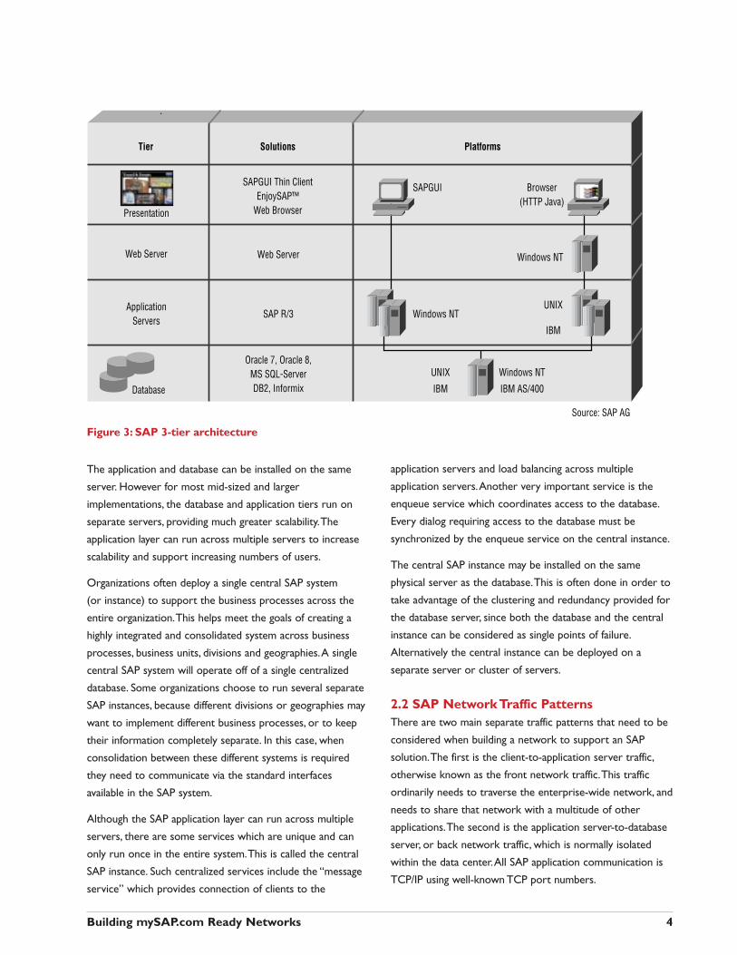
Figure 3: SAP 3-tier architecture
The application and database can be installed on the same
server. However for most mid-sized and larger
implementations, the database and application tiers run on
separate servers, providing much greater scalability.The
application layer can run across multiple servers to increase
scalability and support increasing numbers of users.
Organizations often deploy a single central SAP system
(or instance) to support the business processes across the
entire organization.This helps meet the goals of creating a
highly integrated and consolidated system across business
processes, business units, divisions and geographies.A single
central SAP system will operate off of a single centralized
database. Some organizations choose to run several separate
SAP instances, because different divisions or geographies may
want to implement different business processes, or to keep
their information completely separate. In this case, when
consolidation between these different systems is required
they need to communicate via the standard interfaces
available in the SAP system.
Although the SAP application layer can run across multiple
servers, there are some services which are unique and can
only run once in the entire system.This is called the central
SAP instance. Such centralized services include the “message
service” which provides connection of clients to the
application servers and load balancing across multiple
application servers.Another very important service is the
enqueue service which coordinates access to the database.
Every dialog requiring access to the database must be
synchronized by the enqueue service on the central instance.
The central SAP instance may be installed on the same
physical server as the database.This is often done in order to
take advantage of the clustering and redundancy provided for
the database server, since both the database and the central
instance can be considered as single points of failure.
Alternatively the central instance can be deployed on a
separate server or cluster of servers.
2.2 SAP Network Traffic PatternsThere are two main separate traffic patterns that need to be
considered when building a network to support an SAP
solution.The first is the client-to-application server traffic,
otherwise known as the front network traffic.This traffic
ordinarily needs to traverse the enterprise-wide network, and
needs to share that network with a multitude of other
applications.The second is the application server-to-database
server, or back network traffic, which is normally isolated
within the data center.All SAP application communication is
TCP/IP using well-known TCP port numbers.
Building mySAP.com Ready Networks 4
Tier
Presentation
ApplicationServers
Web Server
Database
Solutions Platforms
SAPGUI Thin ClientEnjoySAP™
Web Browser
SAP R/3
SAPGUI
Windows NT
Windows NTUNIX
IBM
UNIX
IBM
Windows NT
IBM AS/400
Browser(HTTP Java)
Web Server
Oracle 7, Oracle 8,MS SQL-ServerDB2, Informix
Source: SAP AG
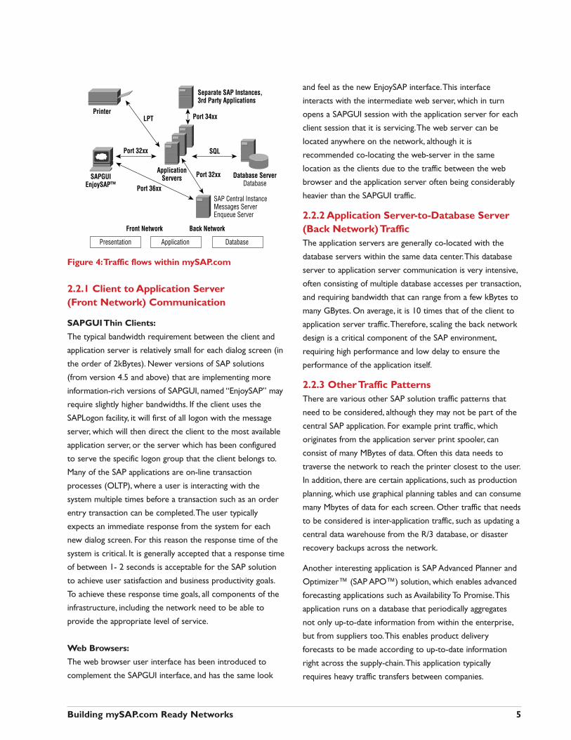
Figure 4:Traffic flows within mySAP.com
2.2.1 Client to Application Server (Front Network) Communication
SAPGUI Thin Clients:
The typical bandwidth requirement between the client and
application server is relatively small for each dialog screen (in
the order of 2kBytes). Newer versions of SAP solutions
(from version 4.5 and above) that are implementing more
information-rich versions of SAPGUI, named “EnjoySAP” may
require slightly higher bandwidths. If the client uses the
SAPLogon facility, it will first of all logon with the message
server, which will then direct the client to the most available
application server, or the server which has been configured
to serve the specific logon group that the client belongs to.
Many of the SAP applications are on-line transaction
processes (OLTP), where a user is interacting with the
system multiple times before a transaction such as an order
entry transaction can be completed.The user typically
expects an immediate response from the system for each
new dialog screen. For this reason the response time of the
system is critical. It is generally accepted that a response time
of between 1- 2 seconds is acceptable for the SAP solution
to achieve user satisfaction and business productivity goals.
To achieve these response time goals, all components of the
infrastructure, including the network need to be able to
provide the appropriate level of service.
Web Browsers:
The web browser user interface has been introduced to
complement the SAPGUI interface, and has the same look
and feel as the new EnjoySAP interface.This interface
interacts with the intermediate web server, which in turn
opens a SAPGUI session with the application server for each
client session that it is servicing.The web server can be
located anywhere on the network, although it is
recommended co-locating the web-server in the same
location as the clients due to the traffic between the web
browser and the application server often being considerably
heavier than the SAPGUI traffic.
2.2.2 Application Server-to-Database Server(Back Network) Traffic The application servers are generally co-located with the
database servers within the same data center.This database
server to application server communication is very intensive,
often consisting of multiple database accesses per transaction,
and requiring bandwidth that can range from a few kBytes to
many GBytes. On average, it is 10 times that of the client to
application server traffic.Therefore, scaling the back network
design is a critical component of the SAP environment,
requiring high performance and low delay to ensure the
performance of the application itself.
2.2.3 Other Traffic PatternsThere are various other SAP solution traffic patterns that
need to be considered, although they may not be part of the
central SAP application. For example print traffic, which
originates from the application server print spooler, can
consist of many MBytes of data. Often this data needs to
traverse the network to reach the printer closest to the user.
In addition, there are certain applications, such as production
planning, which use graphical planning tables and can consume
many Mbytes of data for each screen. Other traffic that needs
to be considered is inter-application traffic, such as updating a
central data warehouse from the R/3 database, or disaster
recovery backups across the network.
Another interesting application is SAP Advanced Planner and
Optimizer™ (SAP APO™) solution, which enables advanced
forecasting applications such as Availability To Promise.This
application runs on a database that periodically aggregates
not only up-to-date information from within the enterprise,
but from suppliers too.This enables product delivery
forecasts to be made according to up-to-date information
right across the supply-chain.This application typically
requires heavy traffic transfers between companies.
Building mySAP.com Ready Networks 5
LPTPrinter
Port 36xx
ApplicationServers Port 32xx
Port 34xx
SQL
Database ServerDatabase
Separate SAP Instances,3rd Party Applications
SAP Central InstanceMessages ServerEnqueue Server
Port 32xx
SAPGUIEnjoySAP™
Presentation Application
Front Network Back Network
Database
3 Network Design Considerations
The underlying network infrastructure is a key success factor
to the successful delivery of SAP applications. Problems
resulting from inappropriate infrastructure can include late
system delivery, poor system performance or unacceptable
downtime at a time when users and management tend to
have high expectations. Furthermore, without correct design,
the network infrastructure may be difficult to scale and adapt
to growth requirements that often rapidly follow an initial
SAP solution deployment. By planning for an end-to-end
network capable of providing enterprise-wide connectivity,
reliability and scalability, it is possible to ensure the successful
initial implementation and subsequent upgrades and
expansions of the system.
In order to best leverage a large investment made in
deploying an SAP enterprise solution, organizations are
interested in making the solution broadly available across the
enterprise, to users in the campus, in remote offices world-
wide, to mobile users and telecommuters to suppliers and
even to customers. SAP 3-tier architecture and well defined
interfaces makes this a very achievable proposition.
Since the majority of companies today are implementing
their SAP enterprise solution as an integrated and
centralized system all clients must access this system across
the appropriate network connection.Also very importantly,
the SAP solution needs to be available to other business-
critical customer facing systems, such as add-on third-party
e-commerce, customer service and supply-chain
management software solutions, which depend on it as the
core enterprise system.
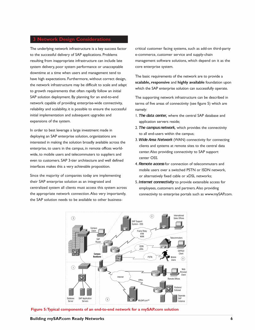
The basic requirements of the network are to provide a
scalable, responsive and highly available foundation upon
which the SAP enterprise solution can successfully operate.
The supporting network infrastructure can be described in
terms of five areas of connectivity (see figure 5) which are
namely:
1. The data center, where the central SAP database and
application servers reside;
2. The campus network, which provides the connectivity
to all end-users within the campus;
3. Wide Area Network (WAN) connectivity for connecting
clients and systems at remote sites to the central data
center.Also providing connectivity to SAP support
center OSS.
4. Remote access for connection of telecommuters and
mobile users over a switched PSTN or ISDN network,
or alternatively fixed cable or xDSL networks;
5. Internet connectivity to provide extensible access for
employees, customers and partners.Also providing
connectivity to enterprise portals such as www.mySAP.com.
Building mySAP.com Ready Networks 6
CampusClient
SAPRouter
SAP SupportSystem - OSS
CampusBackbone
SAP ApplicationServers
SeperateSAPInstance
DatabaseServer
PSTN
InternetVPN’s
WebBrowser
Client
Partners/Extranet
Remote Offices
MySAP.com™
InternationalSales Offices
Telecommuters
MobileUsers
SAPGUIClient
ISDNxDSL
Frame RelayATMWAN
2
1
3
4
5
Figure 5:Typical components of an end-to-end network for a mySAP.com solution
The following diagram shows a simple example of the
various components and networks that typically comprise
an end-to-end mySAP.com solution environment:
We’ll discuss the network requirements and recommended
Cisco solutions and configurations with regards to the data
center, the campus LAN and the Wide Area Network, since
these are generally requirements for all SAP solution
deployments.
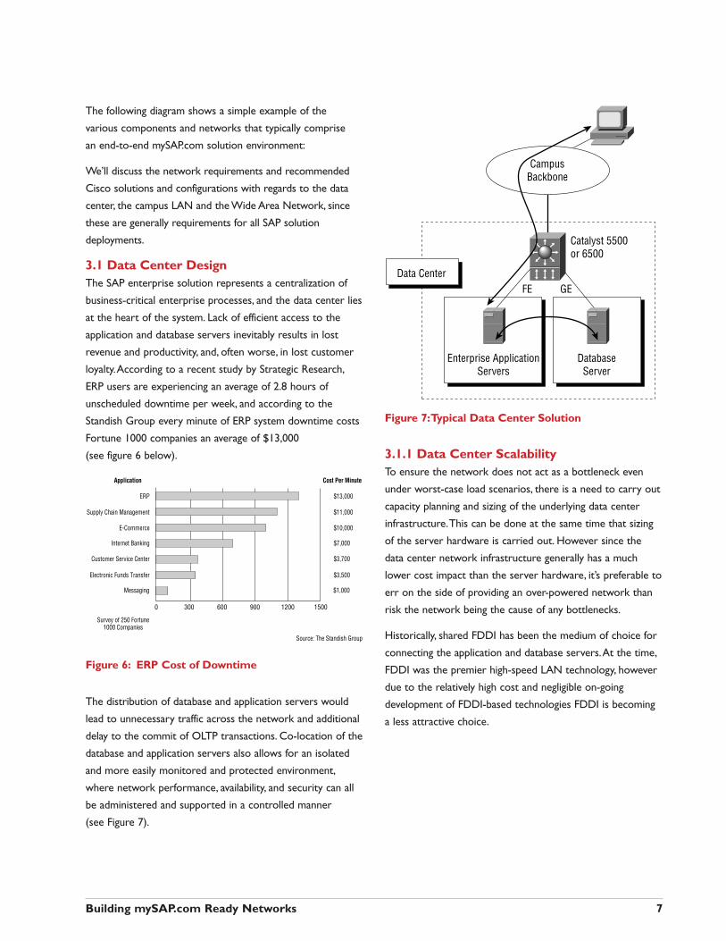
3.1 Data Center Design The SAP enterprise solution represents a centralization of
business-critical enterprise processes, and the data center lies
at the heart of the system. Lack of efficient access to the
application and database servers inevitably results in lost
revenue and productivity, and, often worse, in lost customer
loyalty.According to a recent study by Strategic Research,
ERP users are experiencing an average of 2.8 hours of
unscheduled downtime per week, and according to the
Standish Group every minute of ERP system downtime costs
Fortune 1000 companies an average of $13,000
(see figure 6 below).
Figure 6: ERP Cost of Downtime
The distribution of database and application servers would
lead to unnecessary traffic across the network and additional
delay to the commit of OLTP transactions. Co-location of the
database and application servers also allows for an isolated
and more easily monitored and protected environment,
where network performance, availability, and security can all
be administered and supported in a controlled manner
(see Figure 7).
Figure 7:Typical Data Center Solution
3.1.1 Data Center ScalabilityTo ensure the network does not act as a bottleneck even
under worst-case load scenarios, there is a need to carry out
capacity planning and sizing of the underlying data center
infrastructure.This can be done at the same time that sizing
of the server hardware is carried out. However since the
data center network infrastructure generally has a much
lower cost impact than the server hardware, it’s preferable to
err on the side of providing an over-powered network than
risk the network being the cause of any bottlenecks.
Historically, shared FDDI has been the medium of choice for
connecting the application and database servers.At the time,
FDDI was the premier high-speed LAN technology, however
due to the relatively high cost and negligible on-going
development of FDDI-based technologies FDDI is becoming
a less attractive choice.
Building mySAP.com Ready Networks 7
ERP
Supply Chain Management
E-Commerce
Internet Banking
Customer Service Center
Electronic Funds Transfer
Messaging
$13,000
$11,000
$10,000
$7,000
$3,700
$3,500
$1,000
Cost Per MinuteApplication
Source: The Standish Group
Survey of 250 Fortune1000 Companies
0 300 600 900 1200 1500
Enterprise ApplicationServers
DatabaseServer
Data Center
Catalyst 5500or 6500
FE GE
CampusBackbone
With the wide availability and extensive deployment of Fast
Ethernet and Gigabit Ethernet switching technologies there is
a strong movement towards deploying these technologies in
the data center.With ever-increasing transaction loads, higher
performance servers with increased I/O capabilities and
increasing numbers of users, the need to deploy these higher-
speed switching technologies has become evident. Properly
designed Ethernet technology-based networks can deliver
exceptional performance, fault tolerance, and scalability.
Asynchronous Transfer Mode is another high performance
technology that can be considered, however it is typically
better suited for campus and wide area network backbones
requiring integration of data, voice and video traffic, and does
not present any obvious benefits in the data center.
It is also important to deploy layer 3 and layer 4 capabilities,
through deployment of routers or multi-layer switches.This
enables the isolation of the data center from the high
amounts of irrelevant broadcast traffic that exists on the
campus backbone. It also provides a higher level of security
for the mission-critical data center, keeping out unauthorized
access to these sensitive resources.Also very importantly,
layer 3 and layer 4 capabilities allow traffic to be classified and
prioritized in accordance with business policies that can be
associated with different applications. Increasingly, the
direction is to deploy switches capable of high-performance
switching with millions of packets per second throughput at
both layer 2 and 3. Layer 2 connectivity is recommended
between application and database servers, while inevitably
layer 3 connectivity is required between the application
server and the campus backbone for the client server traffic.
For increased scalability and control, it is recommended to
take a further step in isolating the application server-to-
database server traffic from the client-to-application server
traffic.This is achieved by implementing a separate sub-net
logical network for each traffic type through the
implementation of VLANs and layer 3 switching in the data
center switches.This also requires the installation of separate
application server network interface cards (NICs), each with
separate IP addresses.
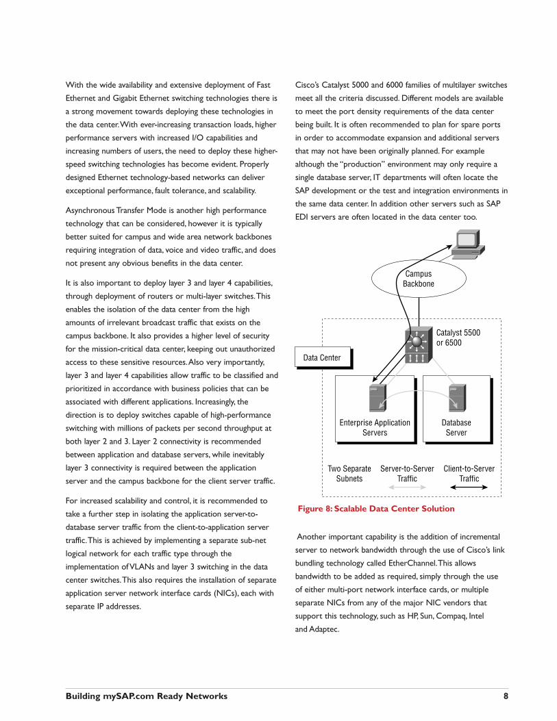
Cisco’s Catalyst 5000 and 6000 families of multilayer switches
meet all the criteria discussed. Different models are available
to meet the port density requirements of the data center
being built. It is often recommended to plan for spare ports
in order to accommodate expansion and additional servers
that may not have been originally planned. For example
although the “production” environment may only require a
single database server, IT departments will often locate the
SAP development or the test and integration environments in
the same data center. In addition other servers such as SAP
EDI servers are often located in the data center too.
Figure 8: Scalable Data Center Solution
Another important capability is the addition of incremental
server to network bandwidth through the use of Cisco’s link
bundling technology called EtherChannel.This allows
bandwidth to be added as required, simply through the use
of either multi-port network interface cards, or multiple
separate NICs from any of the major NIC vendors that
support this technology, such as HP, Sun, Compaq, Intel
and Adaptec.
Building mySAP.com Ready Networks 8
Enterprise ApplicationServers
Two SeparateSubnets
Server-to-ServerTraffic
Client-to-ServerTraffic
DatabaseServer
Data Center
Catalyst 5500or 6500
CampusBackbone
When considering the up-link (switch to campus backbone)
throughput requirement, it is important to note that
normally, the majority of the traffic passing through the data
center switch is server-to-server traffic, which doesn’t need
to reach the campus backbone. It is nevertheless important
to provide a high-speed pipe to ensure that the client-server
traffic is not bottlenecked.Whether a Fast Ethernet or
Gigabit Ethernet connection is chosen for this link, the option
exists to increase the throughput incrementally through the
use of EtherChannel technology. Sometimes, the up-link
connection also needs to service other types of traffic,
besides client-server traffic, such as print traffic, database
consolidation traffic and database back-up traffic. For
instance, if it is decided to implement a remote site disaster
recovery backup for the SAP system, all database changes
need to be periodically or in some cases simultaneously
communicated to the secondary site.This can add a lot of
load to the up-link connection, and will result in an increased
up-link capacity requirement.
3.1.2 Data Center High AvailabilityThe availability of the database and central instance servers is
critical to the continued operation of the system, which in
turn is critical to the efficient operation of the business.With
the globalization of businesses, the requirement is increasingly
for 24 x 7 operation 365 days a year. Much is being invested
in Open System high availability solutions. In particular,
platform vendors are providing server clustering technologies,
capable of providing fast recovery to backup servers in the
case of failures. In addition, database and storage device
vendors are providing database backup technologies to
ensure that data is not corrupted or lost in the case of a
hardware or software failure. Of course none of this
investment will pay off if the network infrastructure does not
provide similar levels of availability. For this reason, SAP
enterprise solutions are increasingly implemented on fully
redundant networks, which provide automatic fault recovery
in the case of any foreseeable device, link or server failure.
Ideally this recovery should be transparent to the user, so that
the application session isn’t affected by the failure. SAP
application sessions typically timeout after 20 seconds, by
default, so that any network recovery should occur within this
timeframe in order to be completely transparent to the user.
This goal extends beyond providing network device reliability,
although this is a key requirement, to ensuring that the
network has the distributed intelligence to quickly recover
from any device or link failure.This intelligence must be
provided through tried and tested software deployed in
devices throughout the network to ensure scalable and stable
rerouting, fast convergence and recovery around any network
problem. In addition, the network must be designed,
configured and maintained to ensure optimal utilization of
these capabilities.
These network devices should ideally be tested in the server
platform environment for the full range of possible failure
scenarios prior to deployment.The network devices, server
clustering technology, operating system and network
interface cards need to all work seamlessly as a single system,
to recover from any server, link or network device failure.
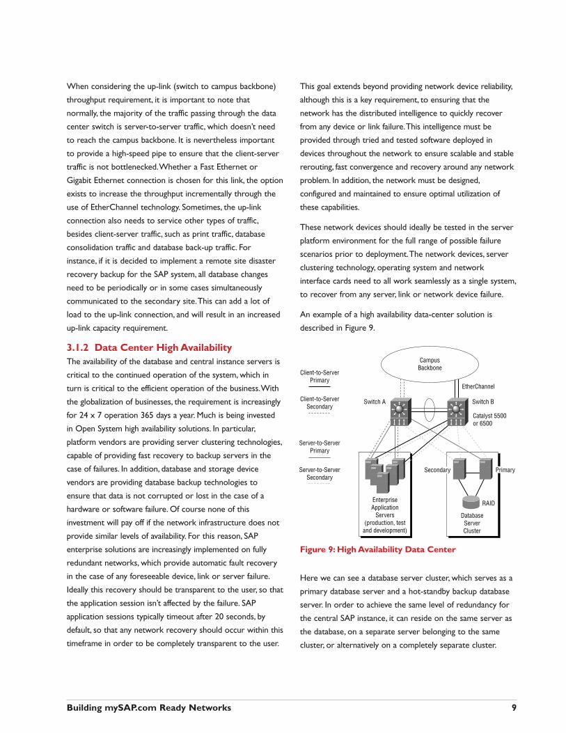
An example of a high availability data-center solution is
described in Figure 9.
Figure 9: High Availability Data Center
Here we can see a database server cluster, which serves as a
primary database server and a hot-standby backup database
server. In order to achieve the same level of redundancy for
the central SAP instance, it can reside on the same server as
the database, on a separate server belonging to the same
cluster, or alternatively on a completely separate cluster.
Building mySAP.com Ready Networks 9
EnterpriseApplication
Servers(production, test
and development)
DatabaseServerCluster
Catalyst 5500or 6500
Secondary
Switch A
Client-to-ServerPrimary
Client-to-ServerSecondary
Server-to-ServerPrimary
Server-to-ServerSecondary
Switch B
EtherChannel
CampusBackbone
Primary
RAID
The other SAP application servers are normally not clustered,
since they by default all provide the same services, and any
failure will only terminate the current sessions running on
that specific server. Users can then immediately re-enter the
system and the message server will simply redirect the user
to one of the other available application servers.
The network configuration shown in Figure 9 includes two
redundant Catalyst 5500 or 6500 switches. Switch A is the
primary switch for server-to-server traffic, and switch B is
the primary switch for client-to-server traffic.Any failure in
any of the switches, line cards, links or database servers, will
automatically result in a convergence around the failure.This
convergence is a result of implementing Cisco high availability
features such as Hot-standby Routing Protocol (HSRP), which
ensures that layer 3 functionality such as default gateway and
routing responsibilities can be transferred to the alternative
switch within seconds, transparent to the server and the
client. In all cases, except where the database server itself
fails, the fast convergence, ensures that the session is not lost,
so that the failure is transparent to the user.
An important aspect of data center resiliency is dual-homing
of servers to separate network switches in order to protect
against a NIC failing or a switch failing.
Dual-homing takes the form of installing two network
Interface cards (NICs) into the server and attaching them
to two different network devices within the server LAN.
Different platform operating systems and NIC vendors will
provide dual-homed NIC’s in different ways, therefore it is
necessary to test and configure the complete system
in unison.
One example of a well-defined configuration is an HP-UX
cluster with MC ServiceGuard clustering software and HP
NICs. In this case, the dual homed NICs share a virtual IP
address, and pass the MAC address from the primary NIC to
the secondary NIC when the primary link or NIC fails.
Another example is the NT dual-homed server, where using
dual NICs from vendors such as Intel, both interfaces can
simultaneously actively transmit data, while only the primary
interface receives data.
Beyond the need for high availability within a single data
center, there is a need in many organizations to provide for
disaster recovery in cases that the data center is destroyed
or access to it is cut off.The levels of disaster recovery will
vary according to the policy of the company.
At one end of the spectrum it may include carrying out
periodic database backups to tape.At the other end of the
spectrum it may include synchronizing a remote database
cluster which is ready to immediately take over in the case of
any failure in the primary site. Disaster recovery and database
backup can be achieved across the enterprise network or
alternatively across a separate network created specifically
for this purpose.
3.2 Campus LAN DesignHaving discussed the data center requirements, let’s now
move to the second building block — the campus.Whereas
the data center is typically an isolated environment, dedicated
to the SAP application and database server traffic, the campus
network needs to support the wide variety of enterprise
applications.
It is generally accepted that the 80/20 rule which once
indicated that 80 percent of network traffic would stay within
the workgroup has been reversed.To a large extent this is a
result of enterprise-wide web-based intranets, messaging and
centralized enterprise applications such as SAP.Today, the
majority of campus traffic no longer is confined to the
workgroup, but now needs to cross the backbone to access
the centralized enterprise resources. In addition, the campus
network needs to be designed in a scalable and flexible
manner to allow addition of more users and deployment of
newer multimedia and voice applications, as the need for
them arises.
Although the bandwidth of 3-tier client-to-application server
traffic can be relatively low (about 2kBytes) per dialog step,
when multiplied by 100s or 1000s of users, this can result in
large increases to existing traffic patterns. Besides regular
client-server traffic, SAP implementations can also be the
catalyst for other traffic, such as server-to-server
communication between an e-commerce system and the
SAP solution and even multimedia traffic associated with
computer-based operator training.
It is highly recommended, wherever possible, to adopt a
modular approach to designing enterprise networks.This
Building mySAP.com Ready Networks 10
approach reduces complexity, which improves availability and
very importantly, also increases the scalability of the network.
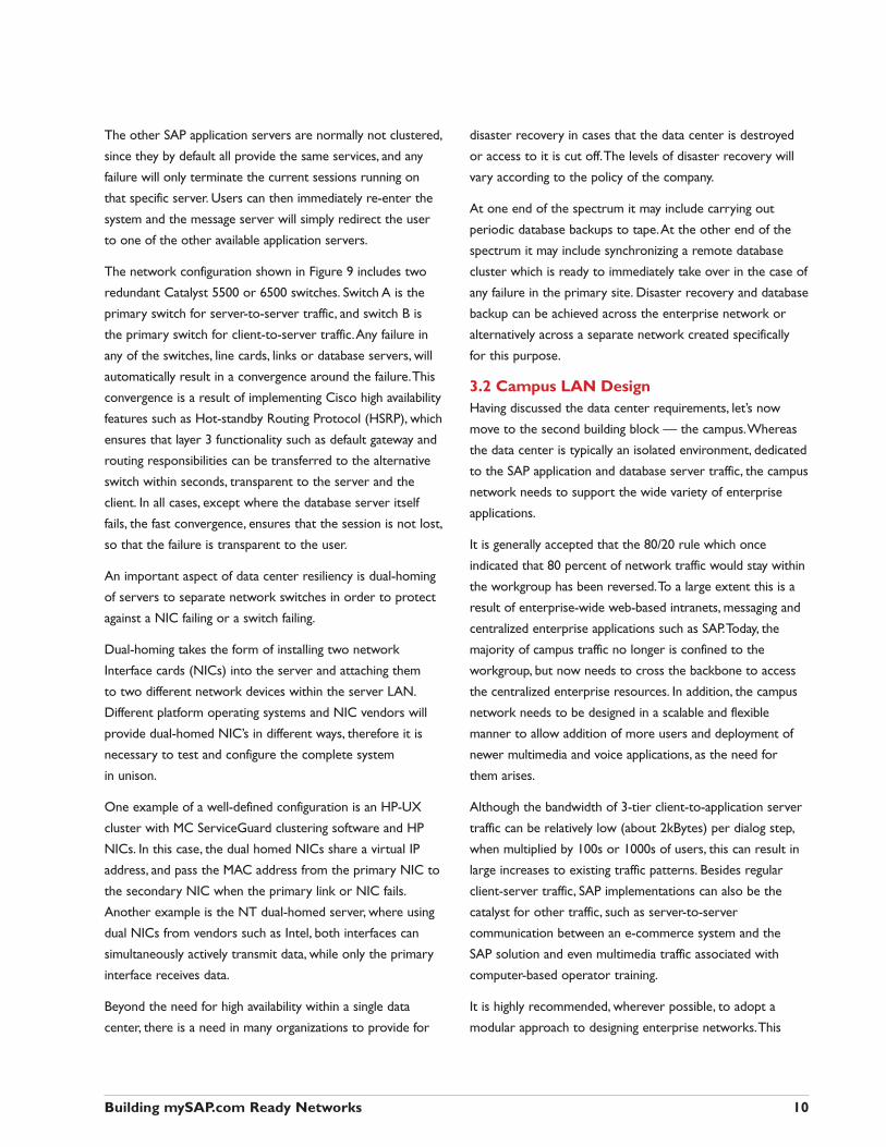
An example of a modular multi-layer design is described in
Figure 10. Here we see the previously described, data center
module, together with three new modules - the core or
backbone module, the distribution module and the access or
wiring center module.
The goal of ensuring that campus located clients and systems
can always achieve access to SAP solution resources in the
data center, depends on the deployment and maintenance of
a highly reliable and resilient campus network. Because the
default timeout of the client-to-server traffic is approximately
20 seconds, networks should be designed to be capable of
recovering from any failure well within this limit.The
approach should be to deploy a network without any single
point of failure, and with the distributed intelligence to
quickly detect and recover from any possible failure. In this
network, there is a backup for every link and every network
device in the path between the client and server.This
approach to network reliability has a number of potential
advantages.
■ The network elements providing redundancy need not be
co-located with the primary network elements.This
reduces the probability that problems with the physical
environment will interrupt service.
■ Problems with software bugs/upgrades or configuration
errors/changes can often be dealt with separately in
the primary and secondary forwarding paths without
interrupting service.Therefore, network-level redundancy
can also reduce the impact of non-hardware failure
mechanisms.
■ With appropriate resiliency features, plus careful design and
configuration, the traffic load between the respective layers
of the network topology (e.g.,Access Layer to Distribution
Layer) can be shared between the primary and secondary
forwarding paths.Therefore, network-level redundancy can
also provide increased aggregate performance and capacity,
which in turn helps to reduce the incremental cost of a
redundant network.
■ Redundant networks can be configured to automatically
fail-over from primary to secondary facilities without
operator intervention.The duration of service interruption
is equal to the time it takes for fail-over to occur. Fail-over
times as low as a few seconds are possible.
Figure 10: Modular Multi-layer Campus Network
The access layer typically consists of high-density layer 2
Ethernet/Fast Ethernet switches installed in wiring closets for
the purpose of user end-station connectivity. Since in most
cases it is unlikely that clients will be dual-homed to separate
switches, these switches can act as a single point of failure for
all attached clients, it may be advisable to configure them for
maximum fault tolerance.The dedicated 10 or 100Mbps
ensure that clients running high bandwidth applications will
not affect the performance of neighboring clients running
mission-critical SAP applications. Multiple high-speed up-links
to the distribution layer provide redundant paths for traffic
propagation.
Once again high availability and fast convergence around any
failure is key. For this reason Cisco has perfected layer 2
recovery technologies such as UplinkFast, which ensure that
any up-link failure is totally transparent to the SAP user.
Cisco provides a range of switches ideally suited to the
access layer, depending on the density required. For high
density switching the Catalyst 5000 family provides support
for large wiring closets (up to 528 clients).The Catalyst 4000
family and the 3500 stackable family provide an appropriate
Building mySAP.com Ready Networks 11
Catalyst4000/5500
Catalyst5500/6500
Catalyst8500/6500
Catalyst5500/6500
10/100 MbpsClients
AccessLayer
DistributionLayer
CoreLayer
DataCenter
solution for medium sized wiring closets , while the Catalyst
2900 Family provides an economic switching solution for
small remote sites
The distribution layer provides a layer 3 aggregation point
for the access layer switches.The distribution layer is typically
required for large campuses supporting many thousands of
users, or where the campus is very geographically dispersed,
otherwise the distribution and core layers can be merged.
The distribution layer is implemented using redundant layer-3
switching (routing) to provide high performance
internetworking and maintain high resiliency between the
multiple connected access layer sub-nets and the core. Cisco
features such as Hot Standby Routing Protocol (HSRP) are
critical to ensuring that failures are completely transparent to
SAP end-users.Well proven layer 3 routing protocols such as
Open Shortest path First (OSPF) and Cisco’s Enhanced
Interior Gateway Routing Protocol (IGRP), provide the layer
3 mechanisms for load-sharing, high resiliency and fast
rerouting around any network problem.The Catalyst 6500 or
Catalyst 5500 are both high performance, scalable and robust
layer 3 switching platforms that build on the experience and
expertise that Cisco has in IP routing.They are both well
suited to the distribution layer.
The core layer is the backbone of the network.The majority
of the network traffic traverses this core, and as such high
performance and high availability are key. Since the backbone
is normally a traversing point for all the aggregated traffic, it
should provide a highly scalable non-blocking architecture,
which can be based on Fast Ethernet, Gigabit Ethernet or
ATM technologies.The core layer should preferably be
implemented using high-performance layer 3 switching
technology, to ensure highly scalable, stable routing around
any possible failure. Once again Cisco’s layer 2 and layer 3
switching, IP routing and ATM technology leadership ensure
that the network core can meet these stringent requirements
placed upon it.
For Ethernet-based backbones both the Catalyst 8500 and
Catalyst 6500 families provide an excellent choice, whereas
for ATM backbones the Catalyst 8500 is once again the right
choice.With regards to additional services required across
the campus, such as multicast, security and voice services, this
will depend on the specific environment and other types of
applications that need to be run across the campus LAN and
WAN environments. For example, if you are using an
application such as TIBCO for SAP application integration,
you will need to support IP multicast across the network.The
rule of thumb is that even if these services are not an
immediate requirement, new applications are likely to require
these services moving forward.With special regard to quality
of service (QoS), as required in an SAP environment, this will
be covered in a later section.
For additional information related to campus network
design see:
http://www.cisco.com/warp/public/779/largeent/design/
large_campus.html
3.3 WAN DesignWith an estimated 50% of all SAP end-users located outside
the campus network, providing scalable and reliable remote
connectivity is critical.The goal of most organizations is to
ensure acceptable performance and availability, while
minimizing the considerable WAN facilities costs, which can
contribute 40-60% to the overall network cost of ownership.
SAP solutions have been well architected for connection of
clients over even relatively slow WAN links, however care still
needs to be taken to ensure that the network is designed and
configured to ensure responsive and highly available
performance.
A wide range of service options exist for the connection of
SAP remote location clients to the central site.These include
Frame Relay,ATM, Leased Line, X.25 and ISDN, and often a
mixture of these will be found in any one organization.
Cisco’s wide range of routing platforms, support the widest
array of services, and ensure the highest levels of
interoperability and functionality.Typically the high-end Cisco
7200 and 7500 can be used at the site of the SAP data center
to provide connectivity to multiple access routers at each of
the remote sites.
Today, Frame Relay is probably the most pervasive service
used for connection of remote sites. Most deployed Frame
Relay networks utilize a “star” or “hub-and-spoke” topology,
which is consistent with the SAP solutions’ requirement for
connecting all clients to a central data center.
Building mySAP.com Ready Networks 12
Increasingly, IP VPN networks are being considered for
connectivity of remote sites, partners customers and remote
users. In this case, the main objective is to enable extensive
cost-effective connectivity to all parties needing to interface
to the SAP system.
3.3.1 WAN Bandwidth RequirementsWhen planning the required WAN bandwidth capacity to
support SAP traffic, together with the other application traffic
crossing the WAN, it is important to carry out analysis of the
existing traffic and the base delay characteristics. For
example, while your primary SAP solution traffic may require
a certain amount of bandwidth, other potential traffic such as
file transfers, printing, e-mail, and Internet access needs to be
considered.When considering the additional bandwidth that
will be required by the new SAP applications the following
estimation can be made.
On average, a dialog step (or screen change) transfers
approximately 2.0KB of data between the application server
and a client.The following SAP formula can be used as a
rough guideline for calculating the additional WAN line
capacity required to support the network traffic between the
application server and clients.
SAP solution bandwidth requirement = 16,000 x Number of Active SAP Users
/ (Dialog Think Time + Response Time) bits/sec.
SAP recommends that line capacity less than or equal to
9.6 Kb should never be employed.
This calculation is a helpful guideline, however it only
accounts for standard SAPGUI access. It does not include
other network traffic requirements, such as voice, e-mail, FTP
or print traffic.As such, it is crucial to create a network traffic
baseline during the SAP solution pre-deployment phase so
that all network requirements can be accounted for within
your design. In addition to the SAPGUI traffic it’s necessary
to consider other associated SAP traffic across the WAN,
such as print traffic, database backup etc.
Besides ensuring that there is enough bandwidth to support
the various applications utilizing the WAN, it’s highly
recommended to use Quality of Service (QoS) mechanisms
to ensure predictable SAP application response times,
even during periods of traffic stress.This is covered in a
later section.
3.3.2 WAN Resiliency
High Availability across the WAN is a major issue, which
needs to be addressed by most companies deploying SAP
applications to remote sites. Cisco routing solutions provide
a full range of features which address this objective.
For remote location redundancy, all major network hubs
should have dual points of access to the WAN service with
dual routers providing load balancing and backup. For smaller
locations the back up media is often ISDN or a second
Frame Relay (permanent virtual circuit) PVC. In other
locations, where diverse routed local loops are not easily
available, companies will often implement alternative
strategies such as satellite links.
Where 24 x 7 service is required, companies cannot afford to
rely purely on the SLA offered by service providers. For this
reason many companies are ensuring that they have full
redundancy, even redundant services from different WAN
service providers.
Some of the advanced Cisco IOS software features which can
help achieve WAN network resiliency include:
■ tunable routing protocol for fast convergence;
■ Hot Standby Routing Protocol (HSRP),
■ load sharing across Layer 3 links,
■ backup links with ISDN or other WAN media,
■ Advanced embedded troubleshooting tools,
■ A wide range of network management tools available for
monitoring and detecting errors.
Building mySAP.com Ready Networks 13
4 Optimizing SAP Applications Across a Network
A key requirement for SAP OLTP environments is to achieve
acceptable response times.This requires that all parts of the
infrastructure, including platform, database, clients and, of
course, the network have the resources and intelligence to
ensure that there are no delays or bottlenecks.
SAP applications are not normally deployed as the first
application on a new network, but rather as a migration from
existing applications on an existing infrastructure.Therefore,
the new SAP application will compete with many other
network uses for a limited amount of resources.
According to the Gartner Group:
■ By 2003, packaged applications such as SAP will be a key
driver in increasing backbone LAN bandwidth ten to
twenty times and WAN bandwidth at least 300 percent.
■ By the year 2000, up to 20 percent of major networked
applications will suffer from severe performance problems.
■ The business demands for QoS for networked applications
and Service Level Agreements (SLAs) for network
performance will render the traditional approach of
bandwidth over-provisioning ineffective.
Whether in new or already existing deployments of SAP
solutions, the need to use QoS exists. QoS refers to the
ability to provide better service to selected networked
applications. If a company experiences SAP application
performance problems due to network congestion, then the
need is obvious.While more bandwidth may appear to be a
viable solution, it is often only temporary because competing
traffic continues to grow.Adding bandwidth can also be the
most costly solution, particularly for wide-area networks.
Another way to mask the problem is by delaying the
deployment of additional business-critical applications, such as
voice and multimedia, in order to protect existing business-
critical SAP traffic. By doing so, a company is not achieving
the additional productivity gains and competitive advantages
so crucial to its business, and is not fully utilizing its network
infrastructure. Other companies may be delaying the
convergence of their disparate networks or WAN links and
foregoing the tremendous benefits possible.
Implementing application-based QoS can solve these
problems and provide the following benefits:
■ Improve end-user satisfaction by consistently meeting SAP
application-response-time needs
■ Faster and more efficient deployment of SAP solutions by
avoiding network problems
■ Lower total cost of ownership (TCO) including minimizing
network infrastructure needs
Deployment of application-based QoS can achieve both
performance and total cost of ownership goals concurrently.
Business managers are normally looking for transaction
response times in the area of a few seconds, while the more
aggressive companies are trying to achieve response times
between one to two seconds.When the actual base delay on
a cross-Atlantic Frame Relay link, for example, can be as
much as 400 msecs, this does not leave much room for
additional delays for congestion across the network or
processing delays in the servers.
4.1 Implementing QoS for SAP ApplicationsQoS should be applied to preferentially expedite SAP
application flows over other less critical traffic such as Web
browsing, e-mail, and file transfers.
Cisco network devices can classify traffic-flows based on both
Layer 3 and Layer 4 parameters, as well as by physical device
interface, enabling selective application of QoS according to
the type of application. In addition, there are efforts underway
to provide increased granularity and flexibility in the
classification of traffic flows, all the way up to layer 7. Here
only the utilization of the layer 3 and layer 4 parameters,
which meet most current SAP requirements, are described:
■ IP source and destination addresses
■ Protocol
■ TCP or UDP source and destination port numbers
Most large SAP installations utilize multiple application
servers. Sometimes multiple physical servers will replicate the
same application, but may be designated to serve different
logon groups or purposes, for example, transaction versus
Building mySAP.com Ready Networks 14
report processing. In many cases, different functional modules
will be configured for separate physical servers. In both these
cases, QoS can be selectively applied by the source and
destination IP address of the servers.
Further classification of SAP application flows can be done
using the layer 4 port numbers used for establishing
TCP/UDP connections over IP.
The default port numbers may be used or new port numbers
configured to handle multiple instances of an application
installation. Unique well-known port numbers which facilitate
application recognition are used by different parts of the
system such as the client server, message server, gateway
server and printing.These port numbers were described in
Figure 4.
4.1.1 What QoS Functions to UseThere are two ways to apply QoS. Differentiated service
prioritizes specific flows by application, user, or content.This
type of service is best for most business-critical traffic
requiring minimized delay and error-free transmission.
Guaranteed service reserves a designated amount of
bandwidth for a specific session and is best suited for traffic
such as video, which has specific and constant bandwidth
requirements.
SAP solutions have the following characteristics that make
differentiated services appropriate.
■ Delay and error sensitive but not bandwidth sensitive
■ Tolerance for some variation in delay
■ Many session flows each using small amounts of bandwidth
■ Bandwidth usage varies with type of transaction
Because SAP applications and the network infrastructures on
which they operate are diverse, it is important to have a
broad range of QoS mechanisms to ensure that the
application needs can be met end-to-end, irrespective of the
media or types of network devices deployed. In addition, it’s
important to implement a signaling mechanism that can signal
the prioritization of different applications end-to-end.
The “Basic QoS Architecture” section below describes the
three components necessary to deliver QoS across a
network comprising heterogeneous technology (IP,ATM, LAN
switches, and so on).
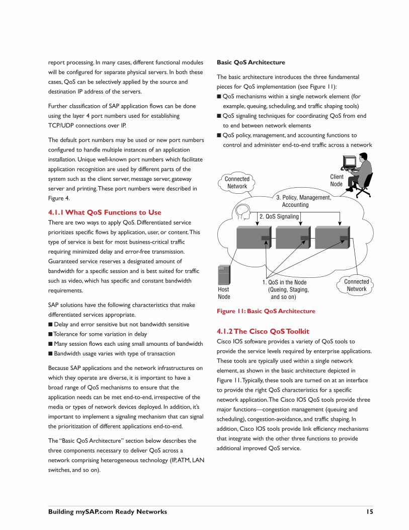
Basic QoS Architecture
The basic architecture introduces the three fundamental
pieces for QoS implementation (see Figure 11):
■ QoS mechanisms within a single network element (for
example, queuing, scheduling, and traffic shaping tools)
■ QoS signaling techniques for coordinating QoS from end
to end between network elements
■ QoS policy, management, and accounting functions to
control and administer end-to-end traffic across a network
Figure 11: Basic QoS Architecture
4.1.2 The Cisco QoS ToolkitCisco IOS software provides a variety of QoS tools to
provide the service levels required by enterprise applications.
These tools are typically used within a single network
element, as shown in the basic architecture depicted in
Figure 11.Typically, these tools are turned on at an interface
to provide the right QoS characteristics for a specific
network application.The Cisco IOS QoS tools provide three
major functions—congestion management (queuing and
scheduling), congestion-avoidance, and traffic shaping. In
addition, Cisco IOS tools provide link efficiency mechanisms
that integrate with the other three functions to provide
additional improved QoS service.
Building mySAP.com Ready Networks 15
3. Policy, Management,Accounting
2. QoS Signaling
HostNode
ClientNode
ConnectedNetwork
ConnectedNetwork
1. QoS in the Node(Queing, Staging, and so on)
Congestion Management Tools
One way that network elements handle an overflow of
arriving traffic is to use a queuing algorithm to sort the traffic,
then determine some method of prioritizing it onto an output
link. Cisco IOS software includes the following queuing tools:
■ Priority queuing (PQ)
■ Custom queuing (CQ)
■ Weighted fair queuing (WFQ)
■ Class-based weighted fair queuing (CB-WFQ)
Each queuing algorithm was designed to solve a specific
network traffic problem and has a unique effect on network
performance.Testing with various enterprise applications has
shown CB-WFQ to be very effective for some application
situations, while CQ has been shown to be most effective
for others.
Congestion-Avoidance Tools
Congestion-avoidance techniques monitor network traffic
loads in an effort to anticipate and avoid congestion at
common network bottlenecks, as opposed to congestion-
management techniques that operate to control congestion
once it occurs.The primary Cisco IOS congestion-avoidance
tool is weighted random early detection (WRED).WRED can
selectively discard lower-priority traffic when the interface
starts to get congested and provide differentiated
performance characteristics of different classes of service.
Traffic-Shaping and Policing Tools
Cisco QoS software solutions include two traffic-shaping
tools—generic traffic shaping (GTS) and Frame Relay traffic
shaping (Frame Relay TS)—to manage traffic and congestion
on the network.
GTS provides a mechanism to control the traffic flow on a
particular interface.Thus, traffic adhering to a particular
profile can be shaped to meet downstream requirements,
eliminating bottlenecks. In topologies with data-rate
mismatches, GTS can use access lists to select the traffic to
shape and works with a variety of layer 2 technologies,
including Frame Relay,ATM, and Ethernet.
Frame Relay TS can eliminate bottlenecks in Frame Relay
networks with high-speed connections at the central site and
low-speed connections at the branch sites.
4.1.3 QoS Signaling Think of QoS signaling as a form of network communication.
It provides a way for an end station or network element to
signal certain requests to a neighbor. For example, an IP
network can use part of the IP packet header to request
special handling of priority or time-sensitive traffic. QoS
signaling is useful for coordinating the traffic handling
techniques described earlier and has a key role in configuring
successful end-to-end QoS service across your network.
True end-to-end QoS requires that every element in the
network path—switch, router, firewall, host, client, and so
on—deliver its part of QoS, and this all must be coordinated
with QoS signaling. However, the challenge is finding a robust
QoS-signaling solution that can operate end-to-end over
heterogeneous network infrastructures.Although many
viable QoS-signaling solutions provide QoS at some places
in the infrastructure, they often have limited scope across
the network.
Cisco IOS software takes advantage of the end-to-end nature
of IP to meet this challenge by overlaying layer 2 technology-
specific QoS-signaling solutions with the layer 3 IP QoS
signaling methods. Such methods include Resource
Reservation Protocol (RSVP) for guaranteed service – more
suitable for applications requiring constant bandwidth - and
IP Precedence which signals differentiated service, well suited
for SAP solutions.
IP Precedence utilizes the three precedence bits in the IPv4
header's type of service (ToS) field to specify class of service
for each packet.You can partition traffic in up to six classes of
service using IP Precedence (two others are reserved for
internal network use).The queuing technologies throughout
the network can then use this signal to provide the
appropriate expedited handling. IP Precedence enables
service classes to be established using existing network
queuing mechanisms (for example,WFQ or WRED) with no
changes to existing applications or complicated network
requirements.
IP Precedence is also being extended to provide additional
granularity and flexibility in support of the newer needs of
voice and video applications, through the newer DiffServ IETF
draft standard.This will extend the current six levels to 64
levels of classification.
Building mySAP.com Ready Networks 16
For detailed information on Cisco QoS networking
solutions, see:
http://www.cisco.com/warp/public/cc/cisco/mkt/ios/tech/
tch/qosio_wp.htm.
4.2 Policy Networking
The intelligent network solutions provided by Cisco present
the user with a rich set of QoS mechanisms to enable SAP
applications. However, utilizing these features can be a
complex exercise for network managers with large networks
to administer.There is a real need to provide dynamic control
and configuration of these QoS functions in a consistent
manner, end-to-end across the intelligent network. Network
devices must be periodically tuned to support increasing
numbers of users, new deployments, user mobility, as well as
ever-increasing new applications.
These customer requirements are being addressed through
policy networking.The need for policy networking is being
driven top-down by business requirements dictated by
market and competitive forces.The network manager needs
to be able to map these business requirements into specific
policies that link the business needs with the desired network
behavior. For example, if an organization is running an SAP
application to achieve strategic competitive advantage, a policy
can be established that give SAP traffic priority to network
resources.The business policy is automatically translated into
network behavior, such as QoS mechanisms and QoS
signaling, to prioritize SAP traffic ahead of other traffic.
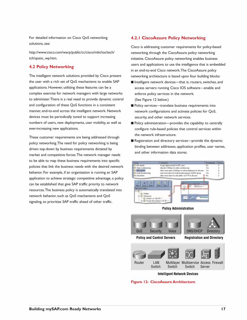
4.2.1 CiscoAssure Policy Networking
Cisco is addressing customer requirements for policy-based
networking through the CiscoAssure policy networking
initiative. CiscoAssure policy networking enables business
users and applications to use the intelligence that is embedded
in an end-to-end Cisco network.The CiscoAssure policy
networking architecture is based upon four building blocks:
■ Intelligent network devices—that is, routers, switches, and
access servers running Cisco IOS software—enable and
enforce policy services in the network.
(See Figure 12 below.)
■ Policy services—translate business requirements into
network configurations and activate policies for QoS,
security, and other network services.
■ Policy administration—provides the capability to centrally
configure rule-based policies that control services within
the network infrastructure.
■ Registration and directory services—provide the dynamic
binding between addresses, application profiles, user names,
and other information data stores.
Figure 12: CiscoAssure Architecture
Building mySAP.com Ready Networks 17
QoS
LANSwitch
Router MultilayerSwitch
MultiserviceSwitch
AccessServer
Firewall
Security
Policy and Control Servers
Intelligent Network Devices
Policy Administration
Registration and Directory
DNS/DHCP DirectoryVoice
4.2.2 Centralized QoS Policy AdministrationCisco QoS Policy Manager (QPM) is a full-featured QoS
policy system that simplifies the complexity of configuring and
deploying QoS policies for enterprise networks. It provides
the key benefits of enabling advanced differentiated services,
automating QoS policy administration and improving the
cost-efficiency of WAN connections. Relying on IP Precedence
to enforce QoS policy end to end, QPM enables network
managers to quickly apply a mix of QoS policy objectives
that protect the performance of business-critical applications,
such as SAP.
The benefits of QPM include:
■ Centralized policy control, through an easy-to-use graphical
user interface that eliminates device-by-device
configuration using a policy-based paradigm for configuring,
modifying, and deploying QoS
■ Tools to simplify configuration of traffic classification and
QoS enforcement policies used by Cisco devices to
achieve application service-level differentiation
■ QoS domain configuration—Intelligent interface grouping
that allows you to selectively enable QoS mechanisms by
policy domain
■ Reliable policy deployment—Policy validation checking,
configuration change previewing, partial access control list
(ACL) updates, and job control facilities that allow you to
reliably deploy QoS policies to Cisco devices
■ Web-based reporting—Web-based reports used to quickly
view and analyze QoS policy deployment
Cisco QoS Policy Manager automates the process of
translating application performance requirements into
QoS policy.
For more information regarding Cisco QoS Policy
Manager, see:
http://www.cisco.com/warp/public/cc/cisco/mkt/enm/cap/
qospm/prodlit/qospm_ds.htm
4.2.3 Monitoring SAP ApplicationPerformanceMost organizations have at least a basic SLA requirement
regarding the performance of SAP transactions.This can be
monitored from SAP CCMS management and monitoring
tools. Newer versions of CCMS are even able to identify the
round-trip SAP client-server traffic delay across the network,
for each transaction or as an average. In this way the network
manager can be alerted as to any possible congestion
occurring on the network, and the resulting slower
performance for SAP transactions.
Cisco provided performance and availability monitoring tools
are able to locate precisely the specific network areas that are
congested, simplifying the network managers’ ability to rectify
the matter through defining and deploying new QoS policies
or adding additional bandwidth to the congested network
segment. Such tools include Cisco Internetwork Performance
Monitor IPM, which takes advantage of imbedded Cisco IOS
agents, which are able to constantly monitor the delays
occurring between any two devices in the network.
Other monitoring tools available include the WAN switch
probes and Traffic Director application, that monitors
WAN SLAs.
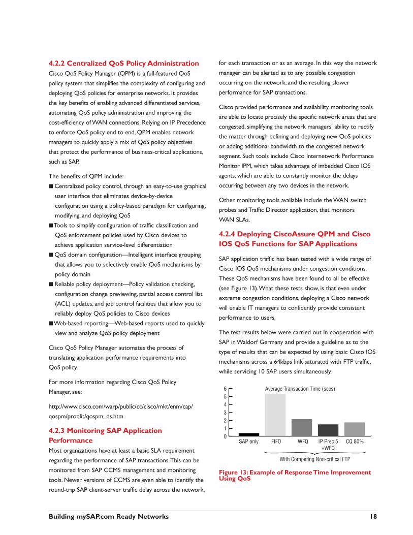
4.2.4 Deploying CiscoAssure QPM and CiscoIOS QoS Functions for SAP Applications
SAP application traffic has been tested with a wide range of
Cisco IOS QoS mechanisms under congestion conditions.
These QoS mechanisms have been found to all be effective
(see Figure 13).What these tests show, is that even under
extreme congestion conditions, deploying a Cisco network
will enable IT managers to confidently provide consistent
performance to users.
The test results below were carried out in cooperation with
SAP in Waldorf Germany and provide a guideline as to the
type of results that can be expected by using basic Cisco IOS
mechanisms across a 64kbps link saturated with FTP traffic,
while servicing 10 SAP users simultaneously.
Figure 13: Example of Response Time ImprovementUsing QoS
Building mySAP.com Ready Networks 18
0SAP only FIFO WFQ IP Prec 5
+WFQCQ 80%
123456 Average Transaction Time (secs)
With Competing Non-critical FTP
5 Conclusion
In summary, SAP solutions make tremendous demands of an
IT organization’s network infrastructure. In order to ensure
the success of these business-critical applications, it’s crucial
that the networking group is involved at an early enough
stage, so that they can plan the deployment of a scalable,
resilient, and intelligent infrastructure.This will help ensure
that the SAP enterprise solution meets the highest
expectations of both the business managers and the users.
Cisco provides the end-to-end solutions required to meet
the stringent demands made by enterprise application
deployments, through technology leadership, experience,
world-class support, and partnerships with software and
hardware vendors, and system integrators.
Specifically Cisco is an SAP Technology Partner, working
closely with SAP to ensure the successful deployment of
enterprise applications. Our collaboration is aimed at
empowering joint Cisco and SAP customers with the
opportunity to take full advantage of the Internet economy.
TM: none
®: Cisco, Cisco IOS, Cisco Systems, Catalyst, EtherChannel, and the Cisco Systems logo
SAP, R/3, mySAP.com, EnjoySAP and all other SAP product and/or service names referenced
herein are trademarks or registered trademarks of SAP AG.
SAP America, Inc.3999 West Chester PikeNewtown Square, PA 19073www.sap.com
Cisco Systems, Inc.170 West Tasman DriveSan Jose, CA 95134-1706www.cisco.com/go/sap
Building mySAP.com Ready Networks
Cisco, Cisco IOS, Cisco Systems and the Cisco Systems logo are registered trademarks of CiscoSystems, Inc. in the U.S. and certain other countries. SAP˙, R/3®, and mySAP.com are the registeredor unregistered trademarks of SAP AG. All other trademarks mentioned in this document are theproperty of their respective owners.The use of the word partner does not imply a partnershipbetween Cisco and any of its resellers. Lit # 953460


![MM Vendor Evaluation - ITtestpapers.com€¦ · Business Scenarios, mySAP.com Application Hosting, ... please refer to the MM Purchasing [Ext.] ... MM Vendor Evaluation SAP AG,](https://img.pdfslide.us/doc/110x75/5ae48daf7f8b9ae74a8f40f0/mm-vendor-evaluation-business-scenarios-mysapcom-application-hosting-.jpg)