Embed Size (px)
Citation preview
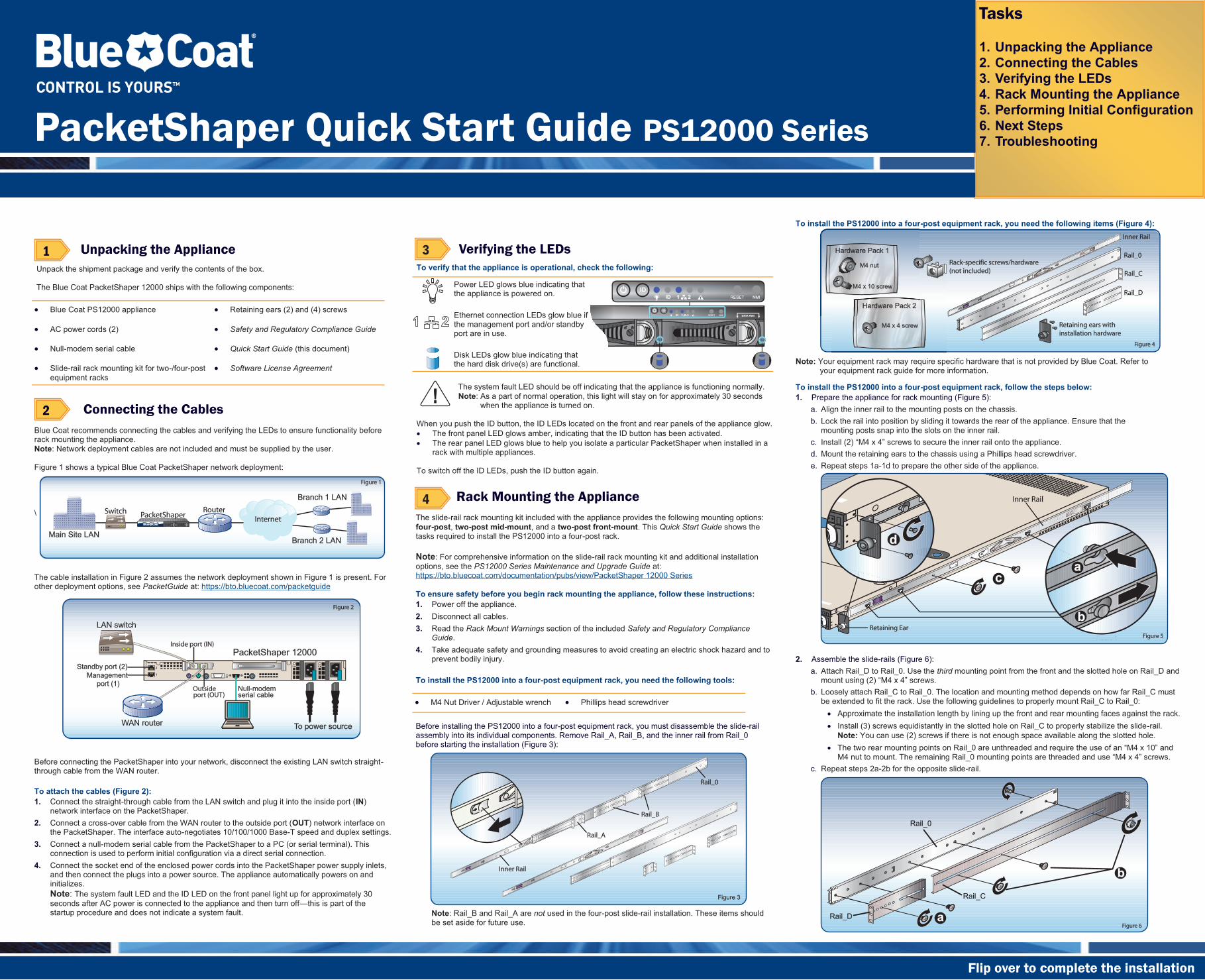
To install the PS12000 into a four-post equipment rack, you need the following items (Figure 4): Note: Your equipment rack may require specific hardware that is not provided by Blue Coat. Refer to your equipment rack guide for more information.
Tasks 1. Unpacking the Appliance 2. Connecting the Cables 3. Verifying the LEDs 4. Rack Mounting the Appliance 5. Performing Initial Configuration 6. Next Steps 7. Troubleshooting
Unpack the shipment package and verify the contents of the box. The Blue Coat PacketShaper 12000 ships with the following components:
Blue Coat PS12000 appliance Retaining ears (2) and (4) screws
AC power cords (2) Safety and Regulatory Compliance Guide
Null-modem serial cable Quick Start Guide (this document)
Slide-rail rack mounting kit for two-/four-post equipment racks
Software License Agreement
Blue Coat recommends connecting the cables and verifying the LEDs to ensure functionality before rack mounting the appliance. Note: Network deployment cables are not included and must be supplied by the user. Figure 1 shows a typical Blue Coat PacketShaper network deployment: \ The cable installation in Figure 2 assumes the network deployment shown in Figure 1 is present. For other deployment options, see PacketGuide at: https://bto.bluecoat.com/packetguide Before connecting the PacketShaper into your network, disconnect the existing LAN switch straight-through cable from the WAN router. To attach the cables (Figure 2): 1. Connect the straight-through cable from the LAN switch and plug it into the inside port (IN)
network interface on the PacketShaper. 2. Connect a cross-over cable from the WAN router to the outside port (OUT) network interface on
the PacketShaper. The interface auto-negotiates 10/100/1000 Base-T speed and duplex settings. 3. Connect a null-modem serial cable from the PacketShaper to a PC (or serial terminal). This
connection is used to perform initial configuration via a direct serial connection. 4. Connect the socket end of the enclosed power cords into the PacketShaper power supply inlets,
and then connect the plugs into a power source. The appliance automatically powers on and initializes. Note: The system fault LED and the ID LED on the front panel light up for approximately 30 seconds after AC power is connected to the appliance and then turn off this is part of the startup procedure and does not indicate a system fault.
3 Connecting the Cables 2
The slide-rail rack mounting kit included with the appliance provides the following mounting options: four-post, two-post mid-mount, and a two-post front-mount. This Quick Start Guide shows the tasks required to install the PS12000 into a four-post rack. Note: For comprehensive information on the slide-rail rack mounting kit and additional installation options, see the PS12000 Series Maintenance and Upgrade Guide at: https://bto.bluecoat.com/documentation/pubs/view/PacketShaper 12000 Series To ensure safety before you begin rack mounting the appliance, follow these instructions: 1. Power off the appliance. 2. Disconnect all cables. 3. Read the Rack Mount Warnings section of the included Safety and Regulatory Compliance
Guide. 4. Take adequate safety and grounding measures to avoid creating an electric shock hazard and to
prevent bodily injury. To install the PS12000 into a four-post equipment rack, you need the following tools:
Before installing the PS12000 into a four-post equipment rack, you must disassemble the slide-rail assembly into its individual components. Remove Rail_A, Rail_B, and the inner rail from Rail_0 before starting the installation (Figure 3):
Note: Rail_B and Rail_A are not used in the four-post slide-rail installation. These items should be set aside for future use.
To verify that the appliance is operational, check the following:
The system fault LED should be off indicating that the appliance is functioning normally. Note: As a part of normal operation, this light will stay on for approximately 30 seconds when the appliance is turned on.
When you push the ID button, the ID LEDs located on the front and rear panels of the appliance glow.
The front panel LED glows amber, indicating that the ID button has been activated. The rear panel LED glows blue to help you isolate a particular PacketShaper when installed in a rack with multiple appliances.
To switch off the ID LEDs, push the ID button again.
Verifying the LEDs
Rack Mounting the Appliance
3 Unpacking the Appliance 1 3
4
Power LED glows blue indicating that the appliance is powered on.
Ethernet connection LEDs glow blue if the management port and/or standby port are in use.
Disk LEDs glow blue indicating that the hard disk drive(s) are functional.
2. Assemble the slide-rails (Figure 6):
a. Attach Rail_D to Rail_0. Use the third mounting point from the front and the slotted hole on Rail_D and
b. Loosely attach Rail_C to Rail_0. The location and mounting method depends on how far Rail_C must be extended to fit the rack. Use the following guidelines to properly mount Rail_C to Rail_0:
Approximate the installation length by lining up the front and rear mounting faces against the rack. Install (3) screws equidistantly in the slotted hole on Rail_C to properly stabilize the slide-rail. Note: You can use (2) screws if there is not enough space available along the slotted hole.
c. Repeat steps 2a-2b for the opposite slide-rail.
To install the PS12000 into a four-post equipment rack, follow the steps below: 1. Prepare the appliance for rack mounting (Figure 5):
a. Align the inner rail to the mounting posts on the chassis. b. Lock the rail into position by sliding it towards the rear of the appliance. Ensure that the
mounting posts snap into the slots on the inner rail. c. d. Mount the retaining ears to the chassis using a Phillips head screwdriver. e. Repeat steps 1a-1d to prepare the other side of the appliance.
M4 Nut Driver / Adjustable wrench Phillips head screwdriver
PacketShaper Quick Start Guide PS12000 Series
Flip over to complete the installation
RECYCLE YOUR OLD BLUE COAT APPLIANCE! Blue Coat offers an easy and sustainable way to recycle your decommissioned Blue Coat appliances. Simply use your new shipping box to send us your old appliance, absolutely free of charge. For details and shipping information, please visit: www.bluecoat.com/company/environment/productrecycling WHY RECYCLE? According to the Silicon Valley Toxics Coalition, nearly 80% of U.S. e-waste is discarded in toxic waste dumps around the world. Without proper recycling, hazardous chemicals and other materials pose serious environmental and health risks. By offering a free and easy-to-use take-back program, Blue Coat enables businesses to efficiently and responsibly dispose of used technology. Find out how! 1. FAST AND EASY TO USE
Use your new appliance carton to ship us your old technology 2. PROTECTS PEOPLE AND THE PLANET
Responsible technology recycling is good for business and the environment 3. ABSOLUTELY FREE
We cover all the costs, including Shipping 4. COMPLETE DETAILS
www.bluecoat.com/company/environment/productrecycling
Recycling Information
-2010 Blue Coat Systems, Inc. All rights reserved worldwide. No part of this document may be reproduced by any means nor modified, decompiled, disassembled, published or distributed, in whole or in part, or translated to any electronic me-dium or other means without the written consent of Blue Coat Systems, Inc. All right, title and interest in and to the Software and
marks contained in this document and in the Software are the property of their respective owners.
BLUE COAT SYSTEMS, INC. DISCLAIMS ALL WARRANTIES, CONDITIONS OR OTHER TERMS, EXPRESS OR IMPLIED, STATUTORY OR OTHERWISE, ON SOFTWARE AND DOCUMENTATION FURNISHED HEREUNDER INCLUDING WITH-OUT LIMITATION THE WARRANTIES OF DESIGN, MERCHANTABILITY OR FITNESS FOR A PARTICULAR PURPOSE AND NONINFRINGEMENT. IN NO EVENT SHALL BLUE COAT SYSTEMS, INC., ITS SUPPLIERS OR ITS LICENSORS BE LIABLE FOR ANY DAMAGES, WHETHER ARISING IN TORT, CONTRACT OR ANY OTHER LEGAL THEORY EVEN IF BLUE COAT SYSTEMS, INC. HAS BEEN ADVISED OF THE POSSIBILITY OF SUCH DAMAGES.
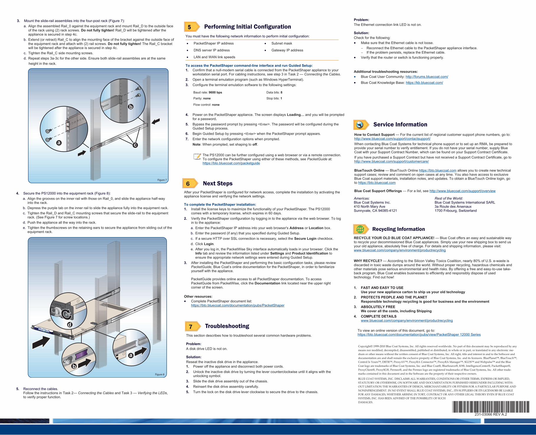
After your PacketShaper is configured for network access, complete the installation by activating the appliance license and verifying the network settings. To complete the PacketShaper installation: 1. Install the license keys to maximize the functionality of your PacketShaper. The PS12000
comes with a temporary license, which expires in 60 days. 2. Verify the PacketShaper configuration by logging in to the appliance via the web browser. To log
in to the appliance: a. Enter the PacketShaper IP address into your web browser's Address or Location box. b. Enter the password (if any) that you specified during Guided Setup. c. If a secure HTTP over SSL connection is necessary, select the Secure Login checkbox. d. Click Login. e. After you log in, the PacketWise Sky interface automatically loads in your browser. Click the
Info tab and review the information listed under Settings and Product Identification to ensure the appropriate network settings were entered during Guided Setup.
3. After installing the PacketShaper and performing the basic configuration tasks, please review PacketGuideyourself with the appliance. PacketGuide provides online access to all PacketShaper documentation. To access PacketGuide from PacketWise, click the Documentation link located near the upper right corner of the screen.
Other resources: Complete PacketShaper document list: https://bto.bluecoat.com/documentation/pubs/PacketShaper
You must have the following network information to perform initial configuration:
To access the PacketShaper command-line interface and run Guided Setup: 1. Confirm that a null-modem serial cable is connected from the PacketShaper appliance to your
workstation serial port. For cabling instructions, see step 3 in Task 2 Connecting the Cables. 2. Open a terminal emulation program (such as Windows HyperTerminal). 3. Configure the terminal emulation software to the following settings:
4. Power on the PacketShaper appliance. The screen displays and you will be prompted for a password.
5. Bypass the password prompt by pressing <Enter>. The password will be configured during the Guided Setup process.
6. Begin Guided Setup by pressing <Enter> when the PacketShaper prompt appears. 7. Enter the network configuration options when prompted.
Note: When prompted, set shaping to off.
3 Performing Initial Configuration 5
3 Next Steps 6
How to Contact Support For the current list of regional customer support phone numbers, go to: http://www.bluecoat.com/support/contactsupport/ When contacting Blue Coat Systems for technical phone support or to set up an RMA, be prepared to provide your serial number to verify entitlement. If you do not have your serial number, supply Blue Coat with your Support Contract Number, which can be found on your Support Contract Certificate. If you have purchased a Support Contract but have not received a Support Contract Certificate, go to http://www.bluecoat.com/support/customercare/ BlueTouch Online BlueTouch Online https://bto.bluecoat.com allows you to create new technical support cases; review and comment on open cases at any time. You also have access to exclusive Blue Coat support materials, installation notes, and updates. To obtain a BlueTouch Online login, go to https://bto.bluecoat.com Blue Coat Support Offerings For a list, see http://www.bluecoat.com/support/overview
3 Service Information
This section describes how to troubleshoot several common hardware problems. Problem: A disk drive LED is not on. Solution: Reseat the inactive disk drive in the appliance. 1. Power off the appliance and disconnect both power cords. 2. Unlock the inactive disk drive by turning the lever counterclockwise until it aligns with the
unlocking symbol. 3. Slide the disk drive assembly out of the chassis. 4. Reinsert the disk drive assembly carefully. 5. Turn the lock on the disk drive lever clockwise to secure the drive to the chassis.
3 Troubleshooting 7 To view an online version of this document, go to: https://bto.bluecoat.com/documentation/pubs/view/PacketShaper 12000 Series
PacketShaper IP address Subnet mask
DNS server IP address Gateway IP address
LAN and WAN link speeds
Baud rate: 9600 bps Data bits: 8
Parity: none Stop bits: 1
Flow control: none
The PS12000 can be further configured using a web browser or via a remote connection. To configure the PacketShaper using either of these methods, see PacketGuide at: https://bto.bluecoat.com/packetguide
4. Secure the PS12000 into the equipment rack (Figure 8): a. Align the grooves on the inner rail with those on Rail_0, and slide the appliance half-way
into the rack. b. Depress the purple tab on the inner rail to slide the appliance fully into the equipment rack. c. Tighten the Rail_D and Rail_C mounting screws that secure the slide-rail to the equipment
rack. (See Figure 7 for screw locations.) d. Push the appliance all the way into the rack. e. Tighten the thumbscrews on the retaining ears to secure the appliance from sliding out of the
equipment rack. 5. Reconnect the cables.
Follow the instructions in Task 2 Connecting the Cables and Task 3 Verifying the LEDs, to verify proper function.
3. Mount the slide-rail assemblies into the four-post rack (Figure 7): a. Align the assembled Rail_0 against the equipment rack and mount Rail_D to the outside face
of the rack using (2) rack screws. Do not fully tighten! Rail_D will be tightened after the appliance is secured in step 4c.
b. Extend (or retract) Rail_C to align the mounting face of the bracket against the outside face of the equipment rack and attach with (2) rail screws. Do not fully tighten! The Rail_C bracket will be tightened after the appliance is secured in step 4c.
c. Tighten the Rail_C side mounting screws. d. Repeat steps 3a-3c for the other side. Ensure both slide-rail assemblies are at the same height in the rack.
Problem: The Ethernet connection link LED is not on. Solution: Check for the following:
Make sure that the Ethernet cable is not loose. Reconnect the Ethernet cable to the PacketShaper appliance interface. If the problem persists, replace the Ethernet cable.
Verify that the router or switch is functioning properly. Additional troubleshooting resources:
Blue Coat User Community: http://forums.bluecoat.com/
Blue Coat Knowledge Base: https://kb.bluecoat.com/
Americas: Blue Coat Systems Inc. 410 North Mary Ave Sunnyvale, CA 94085-4121
Rest of the World: Blue Coat Systems International SARL 3a Route des Arsenaux 1700 Fribourg, Switzerland


![BB4-02 - Burntisland · %xujk %x]] 6sulqj sdj h %oxh )odj :klwh )odj *uhdw qhzv wkdw %xuqwlvodqg lv wr uhwdlq lwv %oxh )odj 5hvruw 6wdwxv 7kh vxjjhvwlrq wkdw rxuµ jxlgholqh¶](https://img.pdfslide.us/doc/110x75/6043ffff88e502613f51ebb6/bb4-02-burntisland-xujk-x-6sulqj-sdj-h-oxh-odj-klwh-odj-uhdw-qhzv-wkdw.jpg)