Embed Size (px)
Citation preview

2-10 FRONTSUSPENSION---------------------·.
44FBJ FRONT AXLE
INDEX
PageAxle Assembly 21
Installation 21Removal 21
Axle Shaft and Joint Assembly 18Assembly 18Disassembly 18Installation 18Removal 18
Differential Bearing Preload and Drive Gear andPinion Backlash 30
Differential Case and Drive Pinion 21Assembly and Installation 24Removal and Disassembly 21
Drag Link 19Installation 20Removal .. , 20
Drive Pinion Depth of Mesh Setting and PinionBearing Preload (Using Tool C-758-D5) 28
Drive Pinion Depth of Mesh Setting and PinionBearing Preload (Using Tool DD-1244) 24
GENERALINFORMATION
This model 44FBJ front driving axle is composed ofthe outer drive assemblies, the differential carrier andtube assembly (axle housing), and the differential caseand drive pinion assembly.
Ball joints are preloaded at manufacture and anylooseness or end play would require them to be reoplaced.
This axle is of the integral carrier-housing, hypoidgear type in which the centerline of the drive pinionis mounted below the centerline of the ring gear.
The axle housing is an iron casting with tubularlegs pressed into and welded to the carrier to form acarrier and tube assembly. A removable stamped steelcover is bolted to the carrier to permit visual inspection of the differential without removing the completeaxle from the vehicle.
A small metal tag is attached beneath one of thecover screws to identify the axle ratio. This tag isstamped with the number of teeth on the drive pinionand ring gear and the axle ratio.
The drive pinion is supported by two preloaded ta-
PageGear Tooth Contact Pattern 31General Information 10Lubrication 31Service Diagnosis 1Service Procedures 10Specifications 49Steering Knuckle and Ball Joint 14
Assembly and Installation , . 14Removal and Disassembly 14
Steering Knuckle Arm 19Installation 19Removal 19
Sway Bar 20Installation 20Removal 20
Tie Rod End 20Installation 20Removal 20
Tightening Reference 50
per roller bearings. The rear pinion bearing cone is atight press·fit on the pinion stem. The front pinionbearing is a light-press fit to a close sliding fit on thepinion stem. The front and rear bearing cups are a .press·fit against a shoulder recessed in the carrier.The drive pinion depth of mesh adjustment is controlled by locating shims, which are installed betweenthe rear pinion bearing cup and the carrier casting.
Drive pinion bearing preload is maintained by usingdifferent thicknesses of shim packs between the drivepinion bearing shoulder and front pinion bearingcone.
The differential case is supported by two taperroller bearing cones which are a press-fit on the differential case hubs. Shims installed between the bearing cone and shoulder of hub of differential case, perform three functions: They eliminate the differentialcase side play; they adjust and maintain the backlashbetween the ring gear and drive pinion; and establisha means of obtaining differential bearing preload.
SERVICE PROCEDURES
SERVICINGROTOR,HUBORBEARINGS
Removal and Disassembly(1) Remove wheel cover. Remove cotter key and
loosen outer axle shaft nut.(2) Raise vehicle to a comfortable working height
and install jack stands. Remove wheel and tire assembly.
(3) Remove caliper retainer and anti-rattle springassemblies. Remove caliper from disc by sliding outand away from disc. Hang caliper out of the way. Donot allow caliper to hang or be supported by hydraulic brake hose. Remove inboard shoe.
(4) Remove outer axle shaft nut and washer. Position Puller, Tool C·4358 over wheel studs and installwheel nuts. Tighten main screw of tool to remove

+---------------------FRONT SUSPENSION2~11
fig. I-Removing Hub and Rotor Assembly withTool C~4358
hub and rotor assembly (Fig. 1).(5) Remove wheel nuts and Puller from hub and
rotor assembly.(6) Using Modified Bearing Press, Tool C-293-PA,
Extension Tool C-293-3 and Adapters, Tool C-293-49,positioned in a vise (Fig. 2), pull the outer bearing conefrom the hub and rotor assembly. Discard outer seal.Remove the six retainer bolts and retainer (Fig. 3).
fig. 2-Removing Outer Bearing with Too' C-293-PA,Extension C-293-3 and Adapter Set C-293-49
Fig. 3-Removing Bearing Retainer
(7) Remove the brake caliper adapter from theknuckle (if required).
(8) Position a pry bar behind the inner axle shaftyoke and push the bearings out of the knuckle (Fig. 4).
(9) Remove the "0" ring from the knuckle (if soequipped) and discard.
nO) Carefully remove the axle shaft assembly.
Inspection(1) Examine the knuckle bore and inner seal sur
face for evidence of severe wear or damage. Replacethe knuckle, if required.
(2) Inspect the outer axle shaft seal surface forgrooving. If the surface is grooved, repair as follows:
(a) Measure in from the yoke shoulder of theaxle approximately 3/8 inch (9.5mm). Using a centerpunch, stake at 1/4 inch (6 mm) intervals around thecircumference of the shaft. This will size the shaft to
insure a tight fit of the inner seal slinger (Fig. 5).(3) Check for proper bearing clamp as follows:
(a) Install the bearing cups and spacer into theknuckle bore (Fig. 6).
fig. 4-Removing Bearings from Knuckle
Irtj

2-12 FRONT SUSPENSfON--------------------t
AXLEHOUSING
STEERINGKNUCKLE
PP223
fig. 5-Staking Axle Shaft
(b) Position the bearing retainer onto the steering knuckle. Install retainer bolts and tighten to 30foot-pounds (Fig. 7).
(c) Insert a .004 inch (.101mm) feeler gauge between the knuckle and the retainer at a point approximately midway between the retainer mounting ears(six places). NOTE: The brake dust shield may haveto be removed to complete this check. If .004 (.101mm)clearance cannot be obtained at each measuring point,the knuckle must be replaced (Fig. 8).
(d) Remove retainer plate, bearing cups andspacer. Install brake dust shield (if removed), tightenmounting bolts to 160 inch-pounds (18 N·m).
Assembly and installation(1) Apply RTV sealer (Silicone Rubber Adhesive
Part :N'o.4026070 or equivalent) to the seal surface ofthe axle shaft.
(2) Using Driver, Tool C-4398-1, install the sealslinger onto the outer axle shaft (Fig. 9).
(3) Install lip seal on the slinger with the liptoward the axle shaft spline (Fig. 10).
fig. 6-lnstaUing Bearing Cups and Spacer
fig. 7-lnsta11iDg ae.....~ R.etainer
(4) Carefully i~ ~..,=:-:.:..L-= ::;''' :r. into the housing soas not to dama~,= '-=,~ =~:-:;::ttal seal at the sidegears.
(5) Insert a :;=--:: :=...- --=--:-.:~-.. the axle shaft "u"joint and wedge 0.: '":,, -=-= a.xle shaft is in all theway and cannot ':'=- :7~:' :=: F~g.11).
(6) Using A:'c:;::f::- -=-:':.~~8-2 and Driver, ToolC-4398-1,carer:':":":',..:3:..L, :.:.'~ 5-e4l cup until bottomedin the knuckle. ~;: -=-:: ..1. ~=La::nount of wheel bearing grease on :~_'=.~_::l:;: :~.:' :;":E ..••Jl aid in holding thecup in positio:: Co: ~C"" ~e the tool at this time.Refer to Figures ~: ::..:::~::
(7) Using Tc:. ~~:.~ ~-:2lI new outer seal in retainer plate. L: :l'f :~~"::='Erplc.:e over hub of rotorassembly.
(8) Thoroug:-.:, ::=:£ Theel bearings with MultiPurpose Grea5f ~:-_~~ Grade 2. E,P. MOPAR MultiMileage Lub::::::..:.::.=...-: ~Ci. 2525035 is a lubricant ofthis kind and :5 ::-::-:-:=.::.ended, or an equivalent.
(9) Using T::: ~-::'c40-A and Adapters positionedas shown in F:~=--= :.;. carefully press outer bearing
BEARIN:::RETAjNE~
PP224
fig. 8-UsJ""9 Feeler Gauge to Cheek Retainer toKnuckle Clearance
+--------------------FRONT SUSPENSION2-13
\AXLE HOUSING
STEERING KNUCKLE
DRIVERTOOL C-4398-1
ADAPTERTOOL C-4398-2
Fig. J 2-Preparing to Install SeOl.C-4398- J and Adapter Co
PP226
Fig. J J -Pry Sar Inserted to Hold Axle Shaft
cup. Correct if necessary.(13) Position the bearing retainer in the hub and
rotor so that the lube fitting is facing directly forward. This is extremely important (Fig. 16).
(14) Assemble the hub and rotor to the knuckleand tighten retainer plate bolts to 30 foot-pounds(41 N'm) using a criss-cross method to position itevenly.
(15) Install brake adapter and tighten mountingbolts to 85 foot-pounds (115 N·m).
(16) Remove pry bar from "U" joint and installaxle shaft washer and nut. Tighten nut to 100 footpounds (136 N'm), continue to tighten nut until nextslot in nut aligns with cotter key hole in axle shaft.Install cotter key.
PPM179
SEAL SLINGER
OUTER AXLESHAFT
ASSEMBLY
Fig. JO-Installing Lip Seal on Axle Shaft
Fig. 9-lnstalling Seal Slinger Using Tool C-4398- J
onto hub. Remove tool.(10) Place grease coated outer bearing cup over
outer bearing cone followed by spacer, grease coatedinner bearing cup and inner bearing cone. Againusing Tool C-4246-A and Adapters positioned as be·fore in Figure 14, carefully press into position. Remove tool.
(11) Apply a 1/4 inch (6 mm) bead of RTV sealer(Silicone Rubber Adhesive Part No. 4026070 orequivalent) to the retainer face on the chamfer (Fig.15) (this takes the place of the "0" ring discarded atdisassembly).
(12) Carefully remove seal installing tool from theknuckle bore so that the outer axle shaft remainscentered. NOTE: If the shaft is disturbed, check tomake sure that the lip seal is still riding inside the

2-14 FRONTSUSPENSION---------------------.
(17) Insert a grease gun through the access hole inthe hub and rotor assembly into the lube fitting. Fillwith Multi-Purpose Grease NLG1, Grade 2, E.P. MOPAR Multi-Mileage Lubricant Part No. 2525035 is alubricant of this kind and is recommended, or anequivalent, until grease flows through the new innerseal (observe at the "U" joint area). Remove lube gunand rotate the hub and rotor several times. Reinstallgrease gun and apply until grease flows from at least50% of the seal diameter.
(18) Locate inboard brake shoe on adapter withshoe flanges in adapter ways. Slowly slide caliper assembly into position in adapter and over disc. Aligncaliper on machined ways of adapter. Be careful notto pull the dust boot from its grooves as the pistonand boot slide over the inboard shoe.
(19) Install anti-rattle springs and retaining clipsand torque to 180 inch-pounds (20 N·m). NOTE: Theinboard shoe anti-rattle spring must always be in·stalled on top of the retainer spring plate.
(20) Install wheel and tire assembly. Tighten nutsto 110 foot-pounds (149 N·m). Install wheel covers.Remove jack stands, lower vehicle and test operation.
STEERINGKNUCKLEANDBALLJOINTRemoval and Disassembly
(1) Remove wheel cover. Remove cotter key andloosen outer axle shaft nut.
(2) Raise vehicle to a comfortable working heightand install jack stands. Remove wheel and tire assembly.
(3) Remove caliper retainer and anti-rattle spring
" 13-Seal Cup Installed with Tool C-4398-1 andAdapter C-4398-2
assemblies. Remove caliper from disc by sliding outand away from disc. Hang caliper out of the way. Donot allow caliper to hang or be supported by hydraulic brake hose. Remove inboard shoe.
(4) Remove outer axle shaft nut and washer.(5) Through hole in rotor assembly remove six re
tainer bolts. Position Puller, Tool C-4358 over wheelstuds and install wheel nuts. Tighten main screw oftool to remove hub, rotor, bearings, retainer and outerseal as an assembly.
(6) Remove wheel nuts and Puller from hub androtor assembly.
(7) Remove the brake caliper adapter from theknuckle.
(8) Position a pry bar behind the inner axle shaftyoke and push the bearings out of the knuckle.
(9) Remove the "0" ring from the knuckle (if soequipped) and discard.
(10) Carefully remove the axle shaft assembly. Remove seal and slinger from shaft.
(11) See "Tie Rod End" "Removal" in this group.Disconnect tie rod from steering knuckle. Left SideOnly-Disconnect drag link from steering knucklearm. See "Drag Link", "Removal" in this group.
(12) Left Side Only-Remove nuts from steeringknuckle arm. Tap steering knuckle arm to loosen tapered dowels. Remove tapered dowels and steeringknuckle arm.
(13) Remove cotter key from upper ball joint nut.Remove upper and lower ball joint nut. Discard lowernut.
(14) Using a brass drift and hammer separatesteering knuckle from axle housing yoke. Using ToolC-4169 remove and discard sleeve from upper balljoint yoke on axle housing.
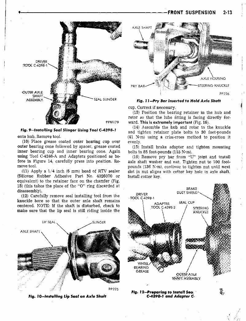
(15) Position steering knuckle upside down in avise and remove snap ring from lower ball joint withC-4020 snap ring pliers (Fig. 17).
(16) Using Tool C-4212-1 and Adapter Set C-4288positioned as shown in Figure 18, press lower ball jointfrom steering knuckle. Reposition tool as shown inFigure 19 and press upper ball joint from steeringknuckle. Replace ball joints if any looseness or endplay exists.
(17) Clean all components with a suitable solventand blow dry with compressed air. Inspect all partsfor burrs, chips, wear or cracks. Replace necessaryparts at assembly.
Assembly and Installation(1) Position steering knuckle, right side up in a
vise. Using Tool C-4212-1 and Adapter Set C-4288positioned as shown in Figure 20, cere fully presslower ball joint into position. Install snap ring withC-4020 snap ring pliers.
(2) Using Tool C-4212-1 and Adapter Set C-4288positioned as shown in Figure 21, carefully press up-

+---------------------FRONT SUSPENSION2-15
per ball joint into position. Install new boots on bothball joints. Remove steering knuckle from vise.
(3) Screw new sleeve into upper ball joint yoke onaxle housing leaving about two threads showing atthe top.
(4) Position steering knuckle on axle housing yokeand install New lower ball joint nut. Tighten to 80foot-pounds (108 N·m).
(5) Using Tool C-4169 and a torque wrench tightensleeve in upper ball joint yoke to 40 foot-pounds (54N·m). Install upper ball joint nut and tighten to 100foot-pounds (136 N·m). Align cotter key hole in studwith slot in castellated nut, if slot and hole are notaligned continue to tighten nut until aligned. Do notloosen to align. Install cotter key.
(6) Left Side Only-Position steering knuckle arm
ROTOR AND HUB ASSEMBLY
(,4246-8
C-4246-3
SP-84
i--III
i
'-I~~~Jr~! ::RETAINERZ(LATE RETAINERPLATE
, ,; jSEAL
, : : 1
'"- ,r~_~~ SP-332
\ ~ r_u.,J / C-4246-6
\ "'-. u==51FI--u~'---n ~.it;n::, II
-=---~:_-J.b-,I'; II;'1 II
C-4246-4
PH1847
fig. J 4-lnstaWng Bearing with Tool C-4246-o4 Components

2-16 FRONTSUSPENSION---------------------.
STEERINGKNUCKLE
PH1850
fig. J8-Removing Lower Sail Joint from SteeringKnuckle
fig. J7-Removing or Installing Snap Ring on LowerSail Joint
(13) Carefully insert axle shaft into the housing soas not to damage the differential seal at the sidegears.
(14) Insert a pry bar through the axle shaft "U"joint and wedge so that the axle shaft is in all theway and cannot be moved out.
(15) Using Adapter, Tool C-4398-2and Driver, ToolC-4398-1,carefully install the seal cup until bottomedin the knuckle. NOTE: A small amount of wheel bearing grease on the Adapter face will aid in holding thecup in position. Do not remove the tool at this time.
(16) Apply a 1/4 inch (6mm) bead of RTV sealer
C-4212-1
ACCESSHOLE
PP228
HUB AND ROTORA~EM&Y
STEERINGKNUCKLE
TIE RODEND
fig. J6-Correct Lubrication fiHing Alignment toKnuckle
BRAKE DUST SHIELD
PP227
Fig. J5-Applying RTVSealer to Retainer Face
over studs on steering knuckle. Install tapered dowelsand nuts. Tighten nuts to 90 foot-pounds (122 N·m).Assemble drag link to steering knuckle arm. Installnut and tighten to 60 foot-pounds (81 N·m). Installcotter key.
(7) Assemble tie rod end to steering knuckle. Install nut and tighten to 45 foot-pounds (61 N·m). Install cotter key.
(8) Inspect the outer axle shaft seal surface forgrooving. If the surface is grooved, repair as notedin, "Servicing Rotor, Hub or Bearings" of this section.
(9) Install brake dust shield (if removed), tightenmounting bolts to 160 inch-pounds (18 N·m).
(10) Apply RTV sealer (Silicone Rubber AdhesivePart No. 4026070 or equivalent) to the seal surface ofthe axle shaft.
(11) Using Driver, Tool C-4398-1, install the sealslinger onto the outer axle shaft.
(12) Install lip seal on the slinger with the liptoward the axle shaft spline.
+---------------------FRONT SUSPENSION
C-4212-1\1
2-11
f;g. 19-Removing Upper 8all Joint from SteeringKnuckle
(Silicone Rubber Adhesive Part No. 4026070 orequivalent) to the retainer face on the chamfer (thistakes the place of the "0" ring discarded at disassembly).
(17) Carefully remove seal installing tool from theknuckle bore so that the outer axle shaft remainscentered. NOTE: If the shaft is disturbed, check tomake sure that the lip seal is still riding inside thecup. Correct if necessary.
(18) Position the bearing retainer on the knuckleso that the lube fitting is facing directly forward. Thisis extremely important.
f;g. 20-lnstalling Lower 8011Jo;nt
fig. 2r-Installing Upper 8011 Joint
(19) Install the hub, rotor, retainer and bearing assembly on the knuckle and tighten retainer platebolts to 30 foot-pounds using a criss-cross method toposition it evenly.
(20) Install brake adapter and tighten mountingbolts to 85 foot-pounds (115 N·m).
(21) Remove pry bar from "U" joint and installaxle shaft washer and nut. Tighten nut to 100 footpounds, continue to tighten nut until next slot in nutaligns with cotter key hole in axle shaft. Install cotterkey.
(22) Insert a grease gun through the access hole inthe hub and rotor assembly into the lube fitting. Fillwith Multi-Purpose Grease NLGl, Grade 2, E.P. MOPAR Multi-Mileage Lubricant Part No. 2525035 is alubricant of this kind and is recommended, or anequivalent, until grease flows through the. new innerseal (observe at the "U" joint area). Remove lube gunand rotate the hub and rotor several times. Reinstallgrease gun and apply until grease flows from at least50% of the seal diameter.
(23) Locate inboard brake shoe on adapter withshoe flanges in adapter ways. Slowly slide caliper assembly into position in adapter and over disc. Aligncaliper on machined ways of adapter. Be careful notto pull the dust boot from its grooves as the pistonand boot slide over the inboard shoe.
(24) Install anti-rattle springs and retaining clipsand torque to 180 inch-pounds (20 N·m): The inboard
shoe anti·rattle spring must always be installed ontop of the retainer spring plate.
(25) Install wheel and tire assembly. Tighten nutsto 110 foot-pounds (149 N·m). Install wheel covers.Remove jack stands, lower vehicle and test operation.

NH182
moving Searing Caps
bearing cap into proper position. Install snap ring.
(3) Remove yoke from vise and work one arm of .~cross into it. Insert opposite bearing cap by hand and" .,.line it up with cross.•....
(4) Replace yoke in vise and press cap into yokeand onto arm of cross (Fig.,24).
(5) With aid '6{ a short plug or socket, press bearing cap into proper posit,ion.Install snap ring.
(6) Repeat procedure as outlined in items 1through 5 for.installing remaining caps and yoke.
Installation(1) Insp~ct the outer axle shaft seal surfac¢.
grooving, If the surface 'is grooved, repair as notiR, "Servicin~ Rotor, Hub or Bearings" of this section ..
(2) Install brake dust shield (if removed), tightenmbunting bolts to 160 inch-pounds'(18 N·m).
(3) Apply RTV sealer (Silicone Rubber AdhesivePart No. 4026070 or equivalent) to the seal surface ofthe axle shaft.
(4) Using Driver,. Tqpl C-4398-1, install the sealslinger onto the outer axle shaft.
o (5) Install lip seal on the slinger with the liptoward the axle shaft spline.
(6) Carefully insert axle shaft into the housing soas ,not to damage the diffe'rential seal at tqe sidegears.
(7) Insert a pry bar through the axle shaft "U,,·joint and wedge so that the axle shaft is in all theway and cannot be moved out.
(8) Using Adapter, Tool C-4398-2 and Driver, ToolC-4,398-1,carefully instalJ the seal cup until bot~omedin the knuckle. A small amount of -wheel bearinggrease on the Adapter face will aid in holding the cupin position. Do not r.emove the tool at this time.
(9) Apply a 1/4 inch (6mm) bead of RTV se~ler(Silicone Rubber Ad~hesivePart No. 4026070 or eguiva:lent) to the retainer face on the chamfer (this takesthe place of the "0" ring discarded at disassembly).
'cJ(~ulti-Mileage LJlbticjent.
Assembly •. \~1)Insert' needle beaPing arid cap assembly in one
ear of yoke.(2) Place yoke in 'vise (Fig. 23) and press needle.
Disas~embly ,.(1) Remove, the snap ri!1gs from the two ears in
each yoke.(2) Position joint assembly in, an. open vise with
one yoke "hqrizontal" anq r'esting on top of vise jaws(Fig, 22), Do not tighten 'vise. ,
, (3) With a' mallet, hip upper ear of "vertical" yokesevel'al times, dri~ing vertIcal yoke down pushing outupper needle bearing and cap..• (4,. Reverse yoke and remove opposite needle bearing and cap...
(5) Work yoke off arms of cross,(6) To complete disa~~embly, position open ends of
cross betwee.n soft jE ,Hf ..V.. is..e and repeat steps 3 and<1to remove remaini ings and cap,
(7) Work cf~'fretf , ke.(8) Clean ~nlr
axle shaft splines:bly separate. If andamaged a complet~stalled t..}··•.~
''l'ic~''''
(9) .!ieltack .'cariI~~'t l'J
2'·18 FRONJ'SUSPENSION--------------------tAXLESHAFTANDJOINTASSEMBLY
••• ~ ~·····'-"n •••,,>:.~, '-:<~l":;~':i .", _.
Removed' , '_0. (1) Remove wheel cover. Remove cotter "key and
• ~OOSElllo}.ltetaxle shaft-nut. ..(2) Raise vehjcle ~o a comfortabie working height
and install jack stands: Remove wheel and tire·assem-,bly... ' , ' .•
(3) R,emove caliper retainer and anti-rattle spr.ing,assemblies. Remove' caliper trqm di!c by:sliding out.
and away f~m d,i.:;c.Han,gcaliper out"of the w~y. Donot~allow ca'fiper to hang or be supported DY hy'draufic brake hose: Remove inboard shoe. ,
(4) R'emoveouter axle shaft nu~ and washer.
,(5) Thro'ugh .ho~n rotor assembly r!'lmove s,ix re:t~er bolts. Position Puller, Tool C-4358 over ""heel
• '1::._ 0
.•. studs and install wheel nuts. Tighten main screw of
•....'~....•.•..tool t.oremov.e..hub, rotor, bearings, retainer, and outerIll. seal as an ass~mbly... ' '.',.' ,(6) Remove 'wheel nuts and Pull,er from hub and
rotor assembly; ,(7),Remove the br'ake caliper adapter froIl). the
knuckle. ' •• '(8) Position a pry bar behind the inner .axle shaft
yoke and push the' bearings out of the knuckle., '(9) Remove the "0" ring from' the knucklll (it so
. equipped) and ,discard.'. , .,(10) Carefully remove the ~le shaft assembly, Re·
moye seal ilnd slinger from shaft.

.•..•
J" e-
+--------------------FRONT SUSPENSION2-19
(10) Carefully remove seal installing tool from theknuckle bore so that the outer axle shaft remainscentered. If the shaft is disturbed, check to make
. sure th~t the lip seal is still riding inside the cup.Correct if necessa ry.
(11) Position the bearing retainer on the knuckleso that the lube fitting is fadng directly forward. Thisis extremely important .•
(12) Install the hub, rotor, retainer and bearing assembly on the knuckle and tighten retainer platebolts to 30 foot-pounds (41 N·m) using a criss-crossmethod to position it evenly.
(13) Install brake adapter and tighten mountingbolts to 85 foot-pounds (115 N·m).
(14) Remove pry bar from "U" join~ and installaxle shaft washer and nut. Tighten nut to 100 footpounds (136 N'm), continue to tighten nut until nextslot in nut aligns with cotter key hole in axle shaft.Install cotter key.
(15) Insert a grease gun through the access hole in.the hub. and rotor assembly into the lube fitting. Fillwith Multi-Purpose Grease NLG1, Grade 2, E.P. MOPAR Multi-Mileage Lubricant Part No. 2525035 is alubricant of this kind and is recommended, or anequivalent, until grease flows through the new innerseal (observ!'l at the "U" joint area). Remove lube gunand rotate the hub and rotor several times. Reinstallgrease gun and apply until grease flows from at least50% of the seal diameter.
(l6) Locate inboard brake shoe on adapter withshoe flanges in adapter ways. Slowly slide caliper assembly into position in adapter and over disc. Aligncaliper on machined ways of adapter. Be careful not.to pull the dust boot from its grooves as the pistonand boot slide over the inboard shoe.
(17) Install. anti-rattle springs and retaining clip~and torque to 180 inch-pounds (20 N·m). The inboardshoe anti-rattle spring must always be installed on
fig. 23-Rep'acing Bearing Caps
top of the retainer spring plate.. (18) Install wheel and tire assembly. Tighten nuts
to 110 foot-pounds (149 N·m). Install wheel covers .Remove jack stands, lower vehicle and test operation.
STEERINGKNUCKLEARM
Removal(1) Raise vehicle to a comfortable working height
and install jack stands.(2) Turn wheels to the left. Remove cotter key and
nut and disconnect drag link. See "Drag Link", "Removal" in this group.
~3) Remove three steering knuckle arm to steeringknuckle mounting nuts. Tap steering knuckle arm tolooseri tapered dowels. Remove tapered dowels andsteering knuckle arm.
Installation(1) Position steering knuckle arm on steering
knuckle. Install tapered dowels and nuts. Tightennuts to 90 foot-pounds (122 N·m). '
(2) Install drag link to steering knuckle arm. Install nut and tighten to 60 foot-pounds (81 N·m). Install cotter key.
(3) Remove jack stands. Lower vehicle and test operation.
DRAGLINK
Drag link seals should be inspected for damage atall oil change periods.
Damaged seals require removal of the seals and inspection of the drag link assembly at the throat opening. If the parts have not lost all the lubricant or arenot contaminated, worn or rusted, use new seals andreinstall, otherwise a new complete drag link assembly should be installed. Lubricate after assembly with
fig. 24-Pressing Cross and Cap into Yoke