Embed Size (px)
Citation preview

UREA AUTOCLAVE FAILURE AND REPAIR
SALEH 1. OURAIDIS
SAUDI ARABIAN FERTILIZER COMPANY (SAFCO) DAMMAM. SAUDI ARABIA
PRESENTED AT
AlCHE 1981 SYMPOSIUM
"Safety in Ammonia Plants and Related Facilities"
MONTREAL. CANADA
October 5 - 8 . 1981

ABSTRACT
On August 10,1978 a t 2330 hours, four mcnths a f t e r inspection during
the 1978 annual plant turnaround, sanething l e a s t expected happened t o
our urea autoclave. While the urea plant was operating s teadi ly a t a
r a t e of 95%. the autoclave developed a leak in the bottan forged head.
A 1% in. (38 mm) long by t in. (6.4 mm) wide hole w a s found. A close
inspection showed some other defective areas varying in depth f r m
3/4 in. (20 mn) t o 2 in. (50 ma).
A t t h a t time of the year, the weather i n Damnam was very hot and h i d
and during the holy month of Ramadan, when a l l mslima ref ra in f raa
eating, drinking, and smoking fran sunrise t o sunset - conditions not
suited t o major maintenance e f for t s .
This paper describes t he de t a i l s of the repair procedure used under
these d i f f i c u l t f i e l d conditions t o bring the p lan t quickly and safely
back i n t o production. The procedure adapted by Safco involved corroded
surface preparation, welding deposit of AWS-E-7016, AWS-E-3 09 and
AWS-E-316L electrodes respectively. A 24-hour cycle post-weld heat
treatment was carried out a f t e r the deposit of AWS-E-309 welding
electrodes. The en t i r e operation, based cn c r i t i c a l path method, took
17 days 20 hours. The autoclave has now been in service for more than
three years. After t h i s repair was carried out, t he metallurgical tests
cmducted by the same inspectors during each of the last three annual
plant turnarounds, have confirmed tha t t he repaired area is metallurgic-
a l l y sound and stable.
INTRODUCTION
Saudi Arabian Fe r t i l i ze r Company (SAFCO) located in Dammw, operates
a f e r t i l i z e r canplex designed by Chemico consisting of a 600 MTD
Amnonia Plant which feeds a 1000 MTD Urea Plant. The ammonia p l an t
is characterized by centrifugal compressors, MEA/CO2 removal system
and medium pressure synthesis loop. The urea plant is a two-stage
decanposition recovery t r a i n followed by evaporators and p r i l l i n g
system. A Sulphur Recovery un i t alongwith Sulphuric Acid Plant were

ins ta l led i n conjunction with the natural gas desulfurization
f a c i l i t i e s . Safco has its own in-home fully-integrated u t i l i t i e s
s y s t w . This plant was commissioned i n l a t e 1969, however, annual
design production could not be attainad u n t i l 1979, a f t e r major
modifications, especially i n t he furnace an13 the urea back-end.
AUTOCLAVE DESIGN FEAWRES
The Urea Autoclave was designed and b u i l t by M / s . Mitsubishi
Heavy Industries Ltd. , Japan. he design pressure and tanpera-
t u re a r e 4015 lbs/sq. in. abs (280 ~ s / c m ~ ) and 4 0 0 ~ ~ ( 2 0 4 ~ ~ )
respectively t o meet an operating pressure and temperature of
3215 lbs/sq.in. abs (226 IGs/un2) and 384'~ (196°~) respectively.
The 5 f t . (1.52 m ) diemeter autoclave shown in Attachment-1 has
an overal l height of 90 ft. (27.43 m ) with 19 t r a y s spaced 4 f t .
(1.02 m ) apart. The vessel is constructed out of 30 multi-layers
Welten 60H, special high t e n s i l e carbon steel she l l al together
making the t o t a l thickness of 5-15/32 in . (139 nun) c a p r i s i n g of
16 short cylinders welded together with top and bottcm forgings
having a thickness varying from 3'1 in. (83 mm) to 3-11/16 in .
(94 mm). The inside of cyl inder ical section of t h e vessel is
lined with 5/8 in. (16 nun) th ick 316L SS.. Two 3/8 in . (9.5 mm)
weep holes through the multi-layer a r e provided f o r each short
cylinder t o indicate l i n e r f a i l u re . The top and bottom forgings
have a s t a in l e s s s t ee l weld overlay deposited by using E-316L
welding rods. The mater ia l of construction of f langes a r e of
A266 CL-2 Class P1 (C 0.35 max. ) , and tha t of t he heads a r e of
A212 G r . B FBQ Class P 1 (ASME A-515, Gr.70, C = 0.31 max. ) . The
area which f a i l ed , namely, the bottom forging has th ree 45 in.
(108 ~mn) dia. nozzles located 60° apar t feeding amnonia, carbon
dioxide and carbarnate respectively with a s t a in l e s s steel ba f f l e
p l a t e umbrella over t he three nozzles.

BACKGWIUND OF THE FAIWRE
Ever since the ccnmnissioning of t h i s autoclave l a t e i n 1969, and
u n t i l August 1978, no major f a i l u r e o r d i f f i c u l t i e s with t h i s
vessel were experienced. In each annuol plant turnaround, the
autoclave was regularly inspected by a thorough visual scanning
of t h e l i ne r seam weld, welds wer l ay and flanges' welds. The
nature of t h e r epa i r s carr ied out in the past were:
1. Rewelding of corroded/pitted semi welds i n t h e l iner .
2 . Replacement of damaged t r ays as found necessary.
3. Replacement of t r ays supports, b o l t s and nuts.
4. Replacement of studs i n the top cover.
5. Replacment of carbamate, and ammonia feed nozzles.
6. Ins ta l la t ion of f i v e oversize studs on the top head.
It may be pointed out t h a t the regular routine inspection was
carr ied out during the May 1978 plant turnaround and no potential
problem had been observed o r foreseen.
On August 10,1978, a t 2330 hours, about 4 months a f t e r annual plant
turnaround, while the Urea Plant was snoothly running a t a r a t e of
95%, the f i e l d operator observed some fuines coming from t h e bottom
of t he autoclave and thought t h a t it was a carbamate flange leak.
He then immediately informed h i s supervisor who, i n turn, called
for maintenance help to handle the matter quickly. Meanwhile,
solution s ta r ted coming out i n large quant i t ies and the en t i r e area
was covered with solution and the team realized t h a t t he solution
was caning out of a hole in t h e reactor bottcm, a l i t t l e away from
the flange. The urea plant was immediately shutdown and the reactor
was drained, flushed and cooled f o r entry.
Operating parameters were reviewed before t he plant shutdown t o be
a t 3115 lbs/sq.in. abs (219 ~ ~ s / c m ~ ) , 381% (194O~), Fe=1.7 ppm,
O2 = 2500 ppm in carban dioxide feed.
It may be worth mentioning tha t the weather i n D a m a t t ha t time
of the year was qui te hot and humid. The ambient temperature was
ranging from 110% (43O~) t o 1 2 0 ° ~ (4g0c) w i t h r e l a t i ve humidity
ranging from 95 t o 100%. Moreover, this w a s the holy month of
Ramadan, when a l l Muslims re f ra in from eating, drinking, smoking,
etc. from sur ise t o sunset. A f a i l u re of t he most important
vessel in the urea plant could hardly have occurred a t a worse
time!
INSPECTION RESULT
Inspection revealed t h a t a wide area around the bottan feed
d is t r ibu tor was severely damaged. Attachment-2 shows the
re la t ive position of these defected areas. Attachment-3 shows
the general views of these defected areas A, B,C,D and E . In
E, the ruptured area, t h i s defect had developed t o an opening
measuring about 1% in. (38 mn) long and 'r in. (6.4 mm) wide with
no other v i s ib l e bulges o r deformation on the outside surface. of
the autoclave bottom. Attachment-4 shows the extent of t h i s damage
a s 3/4 in. (20 mm) i n depth i n (a) area ' D l , 1 in. (35 mm) in (b)
area 'C ' , 2 in. (50 mm) i n (c) area 'A ' and f u l l depth in (d) area
'E ' a s the ruptured area, which showed clear ly t h a t the metal was
eaten up while t he autoclave was i n service. Generally, t he
material loss was found t o be 2 in. (50 nun) i n most places.
POSSIBLE CAUSES OF FAILURE
Carbamate is known t o be extremely corrosive. The corrosion r a t e
is governed by the following:

1. Teaperamre d i rec t ly a f f ec t s the corrosion r a t e
which becanes most pronounced, once a temperature
of 381°~ ( 1 9 4 ~ ~ ) is 'wceeded.
2. Oxygen concentration in t h e feed.
3. huuonia t o Carbon Dioxide ra t io .
4. Flow velocity.
Since the weld overlay metal i s l e s s res i s tan t against corrosion,
the c a n b i ~ t i o n of heat of reaction and high flow veloci ty aver
t he ten years service aside f ran any possible upset in control of
the res idual O2 and the NH3/C02 r a t i o , must have resul ted in a gradual
thinning of the w e r l a y u n t i l in sane areas, it was gradually cons-
umed making the carbon s t e e l t o t a l l y exposed, which then carroded
a t an accelerated speed i n a very short period.
SEARCH FOR ALTERNATIVES
The f a i l u r e of t h i s c r i t i c a l part of the plant meant a long outage
a t the time when Safco Management believed they had f i n a l l y avercane
the plant s h o r t c a h g s and were trying t o achieve design pro&ction
leve ls f o r t he year. I t a l so meant a tedious, long. period of repa i r s ,
in hot and l w i d environment while most of t he employees were fasting.
T h i s problem was reviewed carefully, the repair method was scrutinized,
and the following a l te rna t ives were considered:
(1) Replace the en t i r e autoclave.
(2) Replace the bottan forging of the autoclave.
(3) Carry out a thorough permanent repair .

(4) Carry out a temporary repa i r , followed by
e i the r (11 o r (2) above.
Alternatives (1) and (21 were rejected on the grounds of long
delivery time which, in turn , would mean a tremendous production
l o s s t o a Company t h a t j u s t s ta r ted becoming prof i tab le a f t e r a \ - long period of operating a t loss . It was decided to develop
procedure for a thorough permanent repair o r Alternative (3).
Alternative (3 ) called f o r preheat from outside, be£ ore the
s t a r t of the repa i r , t o 662% ( 3 5 0 ~ ~ ) a t a r a t e of 3 0 0 ~ ~ / h c u r
(167P~/hour) using e l e c t r i c heating pads i n order to eliminate
the diffused hydrogen in t h e parent metal and hold this tempera-
t u r e f o r about an hour and then cool slowly a t a rate of 1 0 0 ~ ~ h o u r
(56%/hour) a s t h i s i s essen t ia l t o e n a r e a sound base metal.
After grinding to renwe cracks to root and a thorough inspection,
the b o t t m forging is t o be preheated to 392OF ( 2 0 0 ~ ~ ) usin7 elec-
t r i c heating pags. This temperature is t o be held throughout t he
welding process. After weld is ocmpleted, the post-weld stress-
relieving is t o be carried out in two hours cycle a t a temperature
of 1100 - 1200% (593 - 64g0c).
ADAPTING OF PROCEDURE
Safco reviewed this proceduze and decided t o r e j e c t the initial
preheat t o 662O~ ( 3 5 0 ~ ~ ) (whichwas recoomended to remove the
diffused hydrogen) and the need t o maintain a temperature of
392% ( 2 0 0 ~ ~ ) during welding process a s it was not prac t ica l
without the use of air-cooled asbestos s u i t s which were not avail-
able. It was real ized t h a t i n this environment even w h i l e using
the air-cooled asbestos su i t s , it knxlld have been impossible t o
carry out a proper welding job, t o conduct a thorough inspection
job, o r t o d i rec t ly supervise the whole process. Moreover, it was a

field-weld involving thin layers of weld deposits contrary t o shop
welding of very thick metal joints. In addition, i n accordance
with American Welding Society, the minimum preheat and interpass
temperature is 1 0 0 ~ ~ (3a0c), when using ASW-E-7016 electrodeswhich,
in our case, happened t o be our ambient temperature during welding.
In view of the above, i t was f e l t t h a t maintaining the preheat and
interpass temperature a t 392OF ( 2 0 0 ~ ~ ) might no t be really ' required.
A s we were not f u l l y sure about the qual i ty of repair which we would
end up with without the i n i t i a l preheat, t h i s a l ternat ive was
s l i gh t ly dri-fted towards a l ternat ive (4) and periodical inspection
programs were implemented t o ensure tha t the repaired area was
s tab le as the original . Telexes were exchanged between Safco
and M/s. Mitsubishi Heavy Industries Ltd., Japan, re la t ive t o the
f a i l u re d e t a i l s and the method of repairs. Mitsubishi agreed to
send a qual i f ied welding engineer and an inspector t o the plant
s i t e and t o work with Safco team during the repairs. Mitsubishi
suggested repair procedure, received l a t e r with t he i r team, w a s
essent ia l ly the same a s had been developed by Safco with the
exception of need t o preheat and t o maintain interpass tempera-
tu res which were rejected i n i t i a l l y by Safco. In addition, they
recanmended the newly developed Thermanit 19/15 H electrodes to
be much superior t o AWS-E-316L t o be used i n autoclave welding
and welding overlays.
AUTOCLAVE REPAIR PROCEDURE CARRIED OUT
1. The en t i r e 316L ss overlay was removed in t he f a i l ed area
and i ts adjoining area using an a i r a r c gouging technique.
2. A l l the exposed carbon s t e e l surface as well as the
corroded areas were ground t o sound metal.
3. A l l voids and cav i t ies were hilt up by normal arc
welding using AWS-E-7016, 5/32 in . (4 ma) dia. electrodes
u n t i l correct wall thickness was reached. After each
bead of weld deposit, care was taken t o remove a l l slag
inclusions. A t the end of the carbon s t e e l welding with
a minimum thickness of 3 in. (76 mm) , dye-penetrant
inspection was carried out.
4. Subsequent t o dye-penetrant inspection of t he carbon
s t e e l weld build-up, the e n t i r e surface was deposited
with one pass of s t a in l e s s s t e e l overlay using AWS-E-309,
5/32 in. (4 mm) dia. electrodesupto a thickness of 1/8 in.
(3.2 ma). After this overlay, the surf ace was ground t o
remove a l l inclusions and surface defects.
5. The bottan of the autoclave was then s t r e s s relieved using
22 pads of Cooperheat f l ex ib l e pad heaters (s ize 16 x 6.75 in.)
with an output of 3.25 KW each. Sixteen pads were used
outside and s ix were used inside. Kaowool was used f o r
insulating the surfaces. The heating was done according
t o the following rates:
a ) Heat upto 6 0 0 ~ ~ ( 3 1 5 ~ ~ ) a t a r a t e of 200°~/hour
( l l l O ~ / h o u r 1.
b) Heat upto 1 1 5 0 ~ ~ (621°c) a t a r a t e of 10oO~/hour
(56Oc/h0w ) .
C ) Hold temperature a t 1 1 5 0 ~ ~ (621°c) for a period
of e igh t hours.
d) Cool a t the same r a t e a s heating.

6. Ultrasonic and magnetic p a r t i c l e s examination was then
carried ou t on t h e repaired area.
7. The e n t i r e surface was then deposited with two layers of
AWS-E-316L, 5/32 in. (4 m) dia. eleotrodes which measured t in.
(6.4 mm) thick.
8. The autoclave was then pressure tes ted gradually upto 5220
lbs/sq.in. abs (367 K!Ss/can2), as shown i n Attachnent-5.
One pass of the newly developed Thermanit 19/l5H electrodes
weld deposit was applied w e r the AWS-E-316L overlay a f t e r two
consecutive inspections in which the repaired art% was found stable.
JOB EXECUTION
After a complete shutdown, draining, and flushing, the autoclave
top cover bas remwed and a l l the t r ays were disassembled. A
manifold was connected from two bottom nozzles through a duct t o
a 16,500 Std. Cu.Ft./min. (7.8m3/Sec. ) @ 85 in. wg (0.22 =/art2)
vacuum machine for f a s t purging and cooling. Wte r , two lh-ton
capacity air-conditioning un i t s Were in s t a l l ed through a special
ducting t o keep the inside of the autoclave more comfortable f o r
inspection and repair work.
The repair work s t a r t ed based on Safco's procedure and the e n t i r e
job was planned on c r i t i c a l path method extending over a period
of 428 hours (17 days 20 hours) which was equivalent t o a t o t a l
of 3400 maintenance manhours. wascarried out by six inde-
pendent crews of four p ipe f i t t e r s , two welders, one r igger and
a supervisor t o work round-the-clock, ins ide the autocalve. The
. f u l l crew uss changed every 4 hours. The welding supervisor as
bll as the inspector were i n cwnstant attendance on 12-hour
s h i f t basis. A telephone comnunication was established between
people working a t t h e bottom of the autoclave, an attendant on
the 19th tray, t he autoclave top, the mt s ide , and the control
room.
The t o t a l electrodes consu&ion was 605 I b s (275 KGs) f o r AWS-E-
7016, 200 lbs (91 KGs) f o r AWS-E-309 and 440 l b s (200 KG=) f o r
AWS-E-316L. A time-table f o r the e n t i r e a c t i v i t i e s is shown in
Attachment-6.
REPAIR INSPECTICN F O W - U P
During 1979 annual p lan t turnaround, the autoclave was opened and
inspected in the presence of Mitsubishi Inspector who was present
during t h e repair and the repaired area was found in good condition.
Later, it was decided t o purchase t h e newly developed Thermanit
19/15 H electrodes f o r fu ture use i n our autoclave.
During 1980 annual plant turnaround, again the autoclave w a s
opened and inspected in the presence of the same Mitsubishi
Inspector and one pass of Thermanit 19/15 H, 5/32 in . (4 nm)
dia. electrodes was deposited on the AWS-E-316L overlay t o '
1/8 in. (32. mm) thickness. A l l in te rna l welding has now been
overlaid with a bead of these electrodes and visual inspection
has mbsequently shown it t o have suffered no corrosion attack.
During 1981 annual plant turnaround, the autoclave was inspected
again in the presence of the same Mitsubishi representative and
the repaired area was found in an excellent condition. The u l t r a -

.sonic scan of the repaired area showed no change from t h a t
immediately a f t e r the repair was made. The repa i r can ' thus be
assumed t o be metallurgically stable.
Subsequent t o t he growing concern w e r l i n e r f a i l u r e and the
oxygen content i n feed t o the autoclave, Safco had discussions
with other urea autoclave owners, and decided t o improrre the air
inject ion system and control t o ensure t h a t the oxygen in t h e
C02 feed concentration is within control l i m i t a t a l l times.
Regular checks a r e made on t h e weep holes t o make sure t h a t t h e
l i n e r i s i n g o d condition.
CONCLUSION
This paper c lear ly shows how careful ly Safco has selected its
procedure t o r epa i r a mp tu re i n one of i t s plant c r i t i c a l vessels
under t he most d i f f i c u l t circumstances of environmental condition.
Highest p r i o r i t y was given t o production ht not a t the expense of
sakety. Safco selected a procedure in repairing the autoclave
bottom forging which minimized downtime ht a t the same time complied
with codes. A l l possible measures were taken t o s a t i s f y the human . needs of our employees during t h e d i f f i c u l t time of fas t ing,and
morale renained high throughout. The job execution was based .on
Cr i t i ca l Path Method and, therefore, was canpleted in the shortest
possible time.
Since this repa i r was carr ied out, our autoclave has been i n
service f o r more than three years and a l l the three metallurgical
t e s t s carr ied out showed the repaired area is metallurgically
s t ab l e and sound a s t h e or ig ina l metal.
SIQ: aac

BIBLIOGRAPHY
1. Mitsubishi Heavy Industries Ltd., Japan, private canmunication
t o Safco.
2. Frank N. Speller, D.Sc., Corrosion Causes and Prevention,
3rd edit ion, Mffiraw-Hill Book Canpany Inc., New York and
London 1951.
3. A.G. Guy, Introduction t o Material Science, McGraw-Hill
Kogakusha Ltd.
4. W i l l i a m G . Moffatt, George W. Pearsal l , John Weff,
Structure, John Willey h Sons Inc.
5. American Welding Society, Welding Handhook, Fundamental
of Welding, 6th edi t ion, Section one.
6. ASME, Boiler and Pressure Vessel Code, Section V I I I ,
Division 1, 1980 edit ion.

SECT. 'A-A
S. A. F. C? 60" 1.0. UREA REACTOR

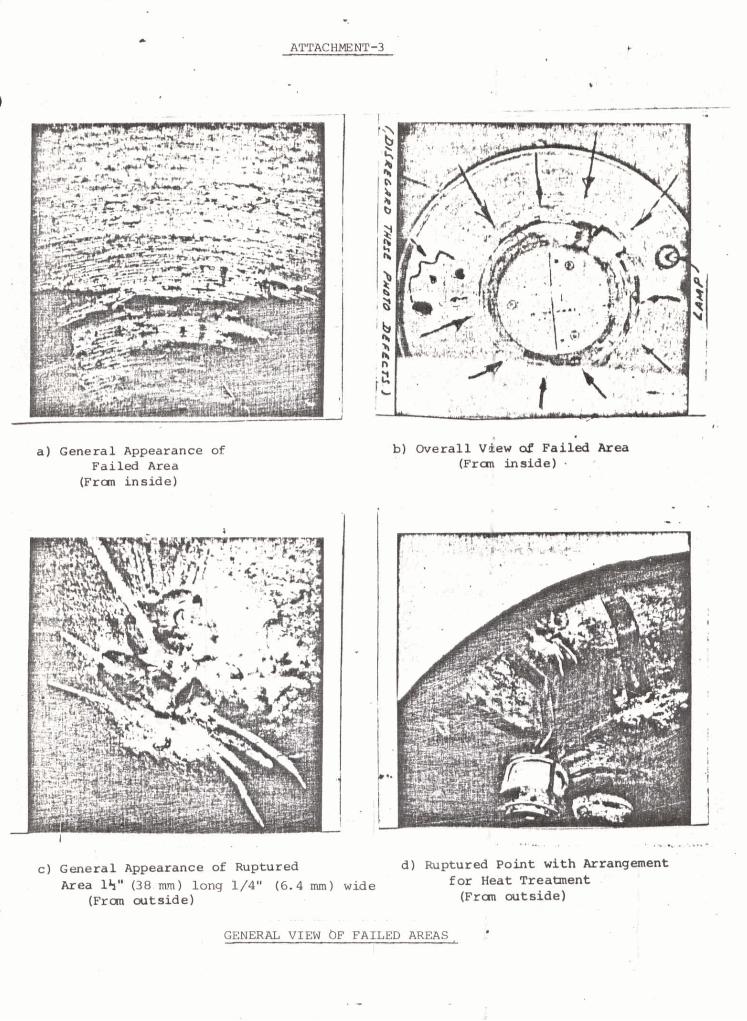
a) General Appearance of Failed Area
(Frm inside)
b) overall view oi ~ a i i e d Area (Frad inside) - *
C ) General Appearance of ~uptured d) Ruptured P o i n t with Mrangment
Area l'i" (38 nun) long 1/4" (6.4 nun) wide for Heat Treatment
(Frao cutside) (Fran cutside)
GENERAL VIEW bF FAILED AREASL
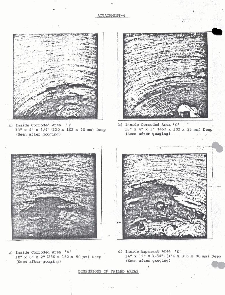
a) Inside Corroded Area 'D' 13" x 4" x 3/4" (330 x 102 x 20 ma) D e e p ( S e e n after gcuging)
C ) Inside ~orrodeh Area ' A ' '
10" X 6" x 2" (250 X 152 x 50 pm) D e e p (Sean after gouging)
b) Inside Corroded .Area 'C' '
18" x 4" x 1" 4457 x 102 x 25 mm) D e e p ( S e e n after gcuging)
DIMENSIONS OF FAILED AREAS