Embed Size (px)
Citation preview
Overload Protection of RCCBs and Switches within Consumer Units
18th Edition
2 Hager White Paper - 18th Edition Overload Protection of RCCBs and Switches within Consumer Units
ContentsExecutive Summary 3
Introduction 4
Where the changes to the regulations originate 4
Pre 18th Edition approach to rated current / overload protection of RCCBs and switches 5 Rated Current derived from maximum demand and diversity 5 InA 5 Inc 5
Overload protection 6
What the regulations say 6 Regulation 536.4.3.2 6 Regulation 536.4.202 6
What the electrical product manufacturers association say 7 Method 1 7 Method 2 7
Overload protection of RCCBs and switches when applied to consumer unit. 8 Method 1 8 Method 2 9
Installations where the upstream protection is known. 10 Method 1 10 Method 2 11
Proposed solutions 12
Conclusion 12
Notes 12
3Hager White Paper - 18th Edition Overload Protection of RCCBs and Switches within Consumer Units
Executive SummaryThe rewriting of chapter 53 of BS 7671:2018 IET wiring regulations has highlighted some areas where designers will have to change their habits when it comes to the selection of consumer units with regard to the rated current of the consumer unit and the rated current(s) of any RCCBs or switches contained within the assembly.
Electrical designers in the UK have traditionally determined the rated current of residual current circuit breakers (RCCBs) and switches after taking into account diversity factors. This method is still the accepted practice. However, the wiring regulations tell us that RCCBs and switches provide no overload protection, therefore, they shall be protected by an overcurrent protective device. The wiring regulations also tell us that overload protection shall not solely be based on the use of diversity factors of the downstream circuits and that overload protection of RCCBs or switches shall be selected to according manufacturer’s instructions.
The electrical manufacturers association (BEAMA²) provide two methods to determine the rated current of switches and RCCBs within an assembly with respect to their overload protection:
- Method 1 – ensure that the rated current of the sum of the downstream MCBs1 do not exceed the rated current of the switch or RCCB when installed within the consumer unit (Inc), or
- Method 2 – ensure that the rated current of the switch or RCCB in the related assembly circuit in the consumer unit (Inc) stated by the assembly manufacturer, is not less than the rated current of the upstream overcurrent protective device (OCPD). For a domestic installation this is likely to be the cut-out fuse rated at 60 A, 80 A or 100 A.
Spare ways offer the potential for future additions to the installation, e.g. additional circuit(s) for electric vehicle charging, electric showers or hot tubs and therefore method 2 would generally be the most robust method to determine the rated current of the switch or RCCB in the related assembly circuit within the consumer unit. However even with method 2, consideration should also be given to the uprating of the supply fuse from 60 A to 80 A, or from 80 A to 100 A to accommodate potential additional circuits and related increased current demand.
Therefore, the most flexible solution would be a consumer unit with an InA 100 A and Inc 100 A for each RCCB protected assembly circuit.
4 Hager White Paper - 18th Edition Overload Protection of RCCBs and Switches within Consumer Units
IntroductionChanges to BS 7671 18th Edition IET wiring regulations released July 2018 have drawn our attention to the specification of RCCBs and switches when incorporated into assemblies such as consumer units in relation to overload protection of these components. This report will highlight the impact of the changes to the regulations on installations, show methods which will allow compliance to be determined and provide robust product solutions.
Regulation 536.4.3.2 states that RCCBs and switches provide no protection against overload therefore they shall be protected by an overcurrent protective device (OCPD). The rated current of this OCPD shall be selected according to manufacturer’s instructions. Regulation 536.4.202 also needs to be taken into account, this states that overload protection shall not solely be based on the use of diversity factors of the downstream circuits. Again manufacturer’s instructions should be used when selecting the OCPD.
Where the changes to the regulations originateA requirement for changes to the regulations was originally highlighted from within the electrical installation industry where it was argued that diversity cannot be used for overload protection. Also, a lack of overload coordination may be related to overheating and adverse effects upon the operating characteristics of RCCBs. These concerns were highlighted to the UK committee responsible for BS 7671.
The wiring regulations take account of the technical substance of agreements reached at CENELEC level in harmonised documents (HD). The technical intent of HD 60364-5-53 November 2015 was implemented into the 18th Edition which included Regulation 536.4.3.2 covering overload protection of an RCCB or switch.
5Hager White Paper - 18th Edition Overload Protection of RCCBs and Switches within Consumer Units
Pre 18th Edition approach to rated current / overload protection of RCCBs and switchesBefore the 18th Edition, the approach was to use the application of diversity factors to determine maximum demand / rated current and an assumption of overload protection for switches and RCCBs.
Rated Current derived from maximum demand and diversity.
Maximum demand is generally calculated with the application of diversity factors. A method to calculate the maximum demand and apply allowances for diversity can be found in Appendix A of the IET on site guide. This guidance gives methods for application to the demand current for individual circuits and also guidance for standard arrangements of final circuits from Appendix H which reads 100% of the current demand of largest circuit +40% of current demand of every other circuit.
In practice this could be a very difficult process for the electrical designer in residential applications as in many cases the actual load(s) are not fully known at the time of design and are likely to alter a number of times during the expected life of the installation. For example, on a new house the actual cooker which is to be installed may not have been selected at the time of design and is likely to be exchanged for a different cooker before the electrical system is updated. Hence it may be prudent to carry out calculations based upon the rated current of the final circuit protective devices e.g. MCBs¹.
Note: There is no change to the methods employed to calculate the maximum demand for an installation, diversity can still be taken into consideration.
Once the maximum demand has been established, the required rated current of the assembly (consumer unit) can be determined (InA).
InA – The rated current of an assembly (consumer unit). This is not necessarily the rating shown in amperes on the incoming device, and is required to be provided on the consumer unit designation label.
Where a split load arrangement of a main switch supplying two RCCBs is used in order to provide additional protection for a group of downstream circuits, the rated current of this group of circuits has the symbol (Inc) and also needs to be taken into account in the same manner as for the complete assembly.
Inc – The rated current of a section within an assembly (assembly circuit). This is not necessarily the rating shown in amperes on the specific devices within the assembly, and is required to be provided in the technical documentation supplied with the consumer unit.
Devices are manufactured to their individual product standards, when they are integrated into an enclosure to form an assembly the assembly (consumer unit) manufacturer carries out further verification of this assembly to determine and validate the rated values shown in their product information.
Overload protection
Generally, overload protection of RCCBs and switches has been related to the application of diversity.
6 Hager White Paper - 18th Edition Overload Protection of RCCBs and Switches within Consumer Units
What the regulations sayAs can be seen from the introduction the 18th Edition IET wiring regulations clearly state that:
Regulation 536.4.3.2 states that devices including; RCCBs complying with BS EN 61008 series, switches complying with BS EN 60947-3 or BS EN 60669-2-4, impulse relays complying with BS EN 60669-2-2 and transfer switching equipment complying with BS EN 60947-6-1 are used to switch loads or circuits. None of these devices provide protection against overload, therefore they shall be protected by an overcurrent protective device (OCPD).
For overload protection of RCCBs and switches the rated current of the OCPD shall take account of manufacturer’s information; in general, the OCPD is installed upstream of the RCCB or switch.
The rated current of a switch or RCCB may also be based on the application of diversity factors to the downstream circuits according to regulation 311.1 and the rated current of the OCPD shall be selected according to the manufacturer’s instructions. See also Regulation 536.4.202
Regulation 536.4.202 states that overload protection shall not solely be based on the use of diversity factors of the downstream circuits. To achieve overload protection of RCCBs or switches, the rated current of the OCPD shall be selected according to manufacturer’s instructions.
For most residential applications the OCPD will be the supply authority fuse. On multi-residential installations this may be a fuse or MCB¹ housed in a TP&N board, a fused distribution board, a switched fuse or similar assembly.
Hence RCCBs and switches shall be protected by an OCPD and that overload protection cannot solely be based on the application of diversity. Both of these regulations state that manufacturer’s instructions (assembly manufacturer’s instructions) shall be used to determine the rating of the OCPD.
The manufacturers of electrical distribution equipment are therefore required to instruct designers and installers on how to determine the rated current of the OCPD for both the assembly (InA) and the related assembly circuits (Inc) within it. BEAMA the leading trade association representing manufacturers of electrical infrastructure products has provided some guidance to assist manufacturers, designers and installers.

7Hager White Paper - 18th Edition Overload Protection of RCCBs and Switches within Consumer Units
What the electrical product manufacturers association sayBritish Electrotechnical and Allied Manufacturers Association (BEAMA) offers guidance on the subject by providing two methods that can be utilised to establish the rated current for the RCCB or switch.
Method 1
The rated current in the assembly circuit Inc(A) of the switch or RCCB shall be greater than or equal to the sum of the rated current of all the associated downstream outgoing circuit OCPDs
Inc2 ≥ In3 + In4 + In5 + In6 + In7
In3
In3 + In4 + In5 + In6 + In7
In4
In1
Inc2
Inc2 ≥
or
or
In5 In6 In7
Method 2
Have a rated current based upon diversity and a suitably rated overload protective device conforming to one of the following: a general-purpose type (gG) fuse to BS 88-3, a circuit breaker to BS EN 60898, a circuit-breaker to BS EN 60947-2 or a residual current circuit breaker with integral overcurrent protection (RCBO) to BS EN 61009-1.
In1 ≤ Inc2
In3 In4
In1
In1
Inc2
Inc2 ≥
or
or
In5 In6 In7
8 Hager White Paper - 18th Edition Overload Protection of RCCBs and Switches within Consumer Units
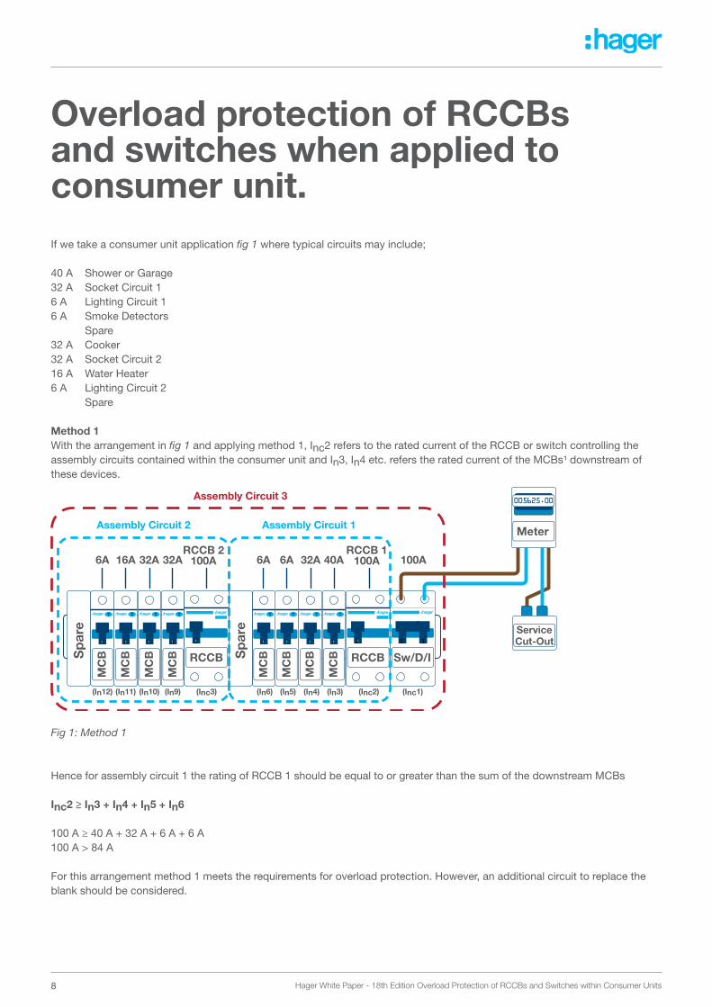
Overload protection of RCCBs and switches when applied to consumer unit.If we take a consumer unit application fig 1 where typical circuits may include;
40 A Shower or Garage32 A Socket Circuit 16 A Lighting Circuit 16 A Smoke Detectors Spare32 A Cooker32 A Socket Circuit 216 A Water Heater6 A Lighting Circuit 2 Spare
Method 1With the arrangement in fig 1 and applying method 1, Inc2 refers to the rated current of the RCCB or switch controlling the assembly circuits contained within the consumer unit and In3, In4 etc. refers the rated current of the MCBs¹ downstream of these devices.
Fig 1: Method 1
Hence for assembly circuit 1 the rating of RCCB 1 should be equal to or greater than the sum of the downstream MCBs
Inc2 ≥ In3 + In4 + In5 + In6
100 A ≥ 40 A + 32 A + 6 A + 6 A100 A > 84 A
For this arrangement method 1 meets the requirements for overload protection. However, an additional circuit to replace the blank should be considered.
Sw/D/I
MC
B
MC
B
MC
B
MC
B
MC
B
MC
B
MC
B
MC
B RCCBRCCBSp
are
Sp
are
Meter
005625.00
Service Cut-Out
RCCB 2 100A
RCCB 1 100A40A32A6A32A32A16A6A
(In9) (Inc3)(In10)(In11)(In12) (In3) (Inc2) (Inc1)(In4)(In5)(In6)
6A 100A
Assembly Circuit 2
Assembly Circuit 3
Assembly Circuit 1
9Hager White Paper - 18th Edition Overload Protection of RCCBs and Switches within Consumer Units
This is then repeated for assembly circuit 2
Inc3 ≥ In9 + In10 + In11 + In12100 A ≥ 32 A + 32 A + 16 A + 6 A100 A > 86 A
For this arrangement method 1 meets the requirements for overload protection. However, the impact of an additional circuit to replace the blank should be considered.
The same methodology needs now to be applied to the main switch assembly circuit 3
Inc1 ≥ In3 + In4 + In5 + In6 + In9 + In10 + In11 + In12100 A ≥ 40 A + 32 A + 6 A + 6 A + 32 A + 32 A + 16 A + 6 A100 A < 170 A
For this arrangement method 1 cannot be used determine overload protection of the main switch. Method 2 should be considered.
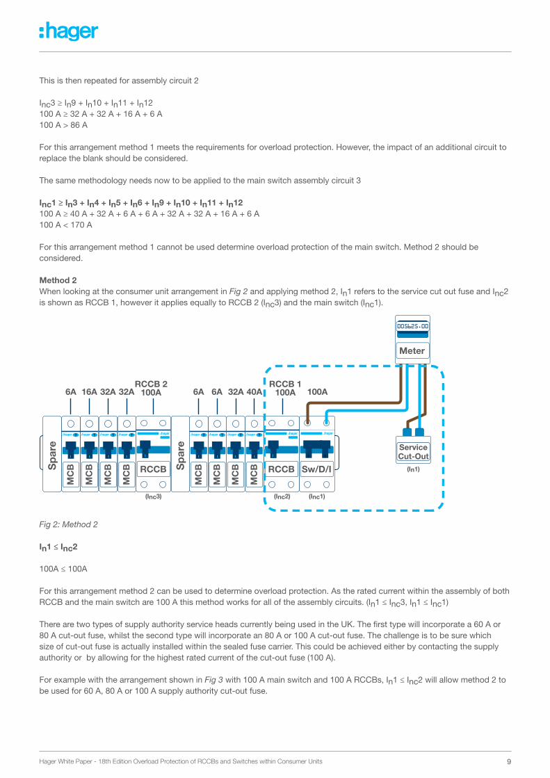
Method 2When looking at the consumer unit arrangement in Fig 2 and applying method 2, In1 refers to the service cut out fuse and Inc2 is shown as RCCB 1, however it applies equally to RCCB 2 (Inc3) and the main switch (Inc1).
Fig 2: Method 2
In1 ≤ Inc2
100A ≤ 100A
For this arrangement method 2 can be used to determine overload protection. As the rated current within the assembly of both RCCB and the main switch are 100 A this method works for all of the assembly circuits. (In1 ≤ Inc3, In1 ≤ Inc1)
There are two types of supply authority service heads currently being used in the UK. The first type will incorporate a 60 A or 80 A cut-out fuse, whilst the second type will incorporate an 80 A or 100 A cut-out fuse. The challenge is to be sure which size of cut-out fuse is actually installed within the sealed fuse carrier. This could be achieved either by contacting the supply authority or by allowing for the highest rated current of the cut-out fuse (100 A).
For example with the arrangement shown in Fig 3 with 100 A main switch and 100 A RCCBs, In1 ≤ Inc2 will allow method 2 to be used for 60 A, 80 A or 100 A supply authority cut-out fuse.
Sw/D/I
MC
B
MC
B
MC
B
MC
B
MC
B
MC
B
MC
B
MC
B RCCBRCCBSp
are
Sp
are
Meter
005625.00
Service Cut-Out
RCCB 2 100A
RCCB 1 100A40A32A6A32A32A16A6A
(Inc3) (Inc2) (Inc1)
(In1)
6A 100A
10 Hager White Paper - 18th Edition Overload Protection of RCCBs and Switches within Consumer Units
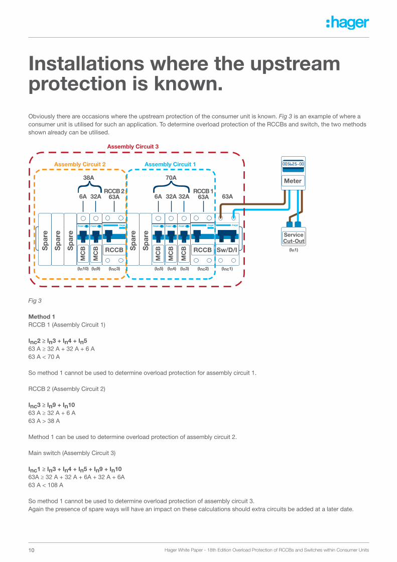
Installations where the upstream protection is known.Obviously there are occasions where the upstream protection of the consumer unit is known. Fig 3 is an example of where a consumer unit is utilised for such an application. To determine overload protection of the RCCBs and switch, the two methods shown already can be utilised.
Fig 3
Method 1RCCB 1 (Assembly Circuit 1)
Inc2 ≥ In3 + In4 + In563 A ≥ 32 A + 32 A + 6 A63 A < 70 A
So method 1 cannot be used to determine overload protection for assembly circuit 1.
RCCB 2 (Assembly Circuit 2)
Inc3 ≥ In9 + In1063 A ≥ 32 A + 6 A63 A > 38 A
Method 1 can be used to determine overload protection of assembly circuit 2.
Main switch (Assembly Circuit 3)
Inc1 ≥ In3 + In4 + In5 + In9 + In1063A ≥ 32 A + 32 A + 6A + 32 A + 6A63 A < 108 A
So method 1 cannot be used to determine overload protection of assembly circuit 3. Again the presence of spare ways will have an impact on these calculations should extra circuits be added at a later date.
Sw/D/I
MC
B
MC
B
MC
B
MC
B
MC
B RCCBRCCB Sp
are
Sp
are
Sp
are
Sp
are
Sp
are
Meter
005625.00
Service Cut-Out
RCCB 2 63A
RCCB 1 63A32A32A6A32A6A 63A
38A 70A
(In9) (Inc3)(In10) (In3) (Inc2) (Inc1)
(In1)
(In4)(In5)
Assembly Circuit 2
Assembly Circuit 3
Assembly Circuit 1
11Hager White Paper - 18th Edition Overload Protection of RCCBs and Switches within Consumer Units
Method 2 (In1 ≤ Inc2)
In this example the rated current of the cut-out fuse is crucial.
For a 60 A cut-out fuse method 2 can be used to determine overload protection, however, for an 80 A or 100 A cut-out fuse method 2 cannot be used to determine overload protection. This applies equally for an 80 A rated RCCB and main switch arrangement with an 80 A supply authority fuse.
If we look at the principles applied to conductors on the same installation. The current carrying capacity of a cable for continuous service under the particular installation conditions concerned (Iz) should be equal to or greater than the rated current or current setting of protective device (In) represented by the formula Iz ≥ In. This is demonstrated for instance with the selection of meter tails to BS 6004 for a consumer unit, where a 60 A cut-out fuse is installed it is common for a 16mm² meter tail to be selected, however where a 100 A cut-out fuse is installed and the cables are clipped direct 25mm² meter tails would typically be installed. The sizing of these conductors for overload protection is determined by the upstream fuse and not by using the diversified downstream loads
12 Hager White Paper - 18th Edition Overload Protection of RCCBs and Switches within Consumer Units
Proposed SolutionsOn installations where the designer is required to make so many assumptions in relation to the characteristics of the loads, along with the very real prospect of additional circuits in the coming years to provide for example for electric vehicle charging, ensuring the correct selection of consumer unit is essential.
As can be seen from the examples in the previous section, method 1 is difficult to implement where there is a possibility for an additional circuit(s) to be added. It is suggested that method 2 is a more robust method for anticipating future demands.
This suggests that the solution where the rated current of the consumer unit InA and the rated current of the related assembly circuits within the consumer unit Inc are equal to or greater than the rated current of the upstream protection. On installations where the rated current of the cut-out fuse is not known, it would be prudent to design for the highest rated current of cut-out fuse i.e. a 100 A fuse resulting in the specification for the split load consumer unit being 100 A InA, with related RCCB assembly circuits 100 A Inc to provide overload protection for RCCBs and switches in line with the 18th Edition IET wiring regulations.
ConclusionWith the introduction of the 18th Edition of BS 7671:2018 IET wiring regulations electrical designers will need to ensure that they specify the correct consumer unit rated currents with regards to overload protection of RCCBs and switches. This paper has identified two methods which can be implemented to achieve overload protection for RCCBs and switches:
Method 1 – ensure that the sum of the rated current of the downstream MCBs do not exceed the rated current of the switch or RCCB. This method would need to consider the consequences of any spare ways and later additions.
Method 2 – ensure that the rated current of a switch or RCCB stated by the assembly manufacturer is not less than the rating of the upstream OCPD. In a domestic installation this could be a 60 A, 80 A or 100 A cut-out fuse.
Notes:1 ‘MCB’ is used as generic term for a circuit breaker to BS EN 60898.2 BEAMA, British Electrotechnical and Allied Manufacturers Association.
13Hager White Paper - 18th Edition Overload Protection of RCCBs and Switches within Consumer Units
Hager Ltd.Hortonwood 50TelfordShropshireTF1 7FT
Sales Service Centre: 01952 675612Technical Service Centre: 01952 675689
[email protected]@hager.co.uk
Hager Ltd. - IrelandUnit M2Furry Park Industrial EstateSwords RoadSantry Dublin 9D09 NY19Ireland
Republic of Ireland Tel: 1890 551 502Republic of Ireland Fax: 1890 551 503Northern Ireland Tel: 00 44 7968 147444Northern Ireland Fax: 00 353 1 8869520