Embed Size (px)
Citation preview
01
Have you got questions regarding the changes to the wiring regulations?
We’ve got you covered in this bitesize guide.
18th EditionBitesize Guide

02
03
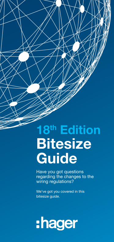
BS 7671:2018 was issued on 2nd July 2018 and came into effect on 1st January 2019. It is the latest in a series of documents giving the requirements for electrical installations.
Installations designed after 31st December 2018 are to comply with BS 7671:2018.
The Regulations apply to the design, erection and verification of electrical installations, also additions and alterations to existing installations.
Existing installations that have been installed in accordance with previous editions of the Regulations may not comply with this edition in every respect. This does not necessarily mean that they are unsafe for continued use or require upgrading.
This guide does not give the entire information regarding the 18th Edition or indeed only changes from the 17th. If after reading this guide you would like to find out further information regarding the new regulations Hager offer tailored training courses. To register an interest in attending one of these courses please visit hager.co.uk/training

Table of Contents
Protection Against Electric Shock - Disconnection times &
additional protection with RCD
06
Protection Against Fire Caused by Electrical Equipment
08
Protection Against Transient Overvoltages of Atmospheric Origin or Due to Switching
10
Supporting of Cables Against Premature Collapse
12
Selection of Types of RCD 14
Overload Protection of RCCB’s Switches etc.
16
Selection of Compatible Devices Within an Assembly
18
06
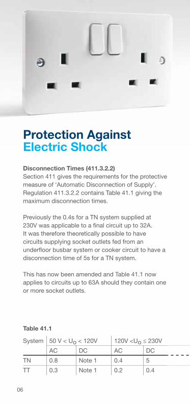
Protection Against Electric Shock
Disconnection Times (411.3.2.2)Section 411 gives the requirements for the protective measure of ‘Automatic Disconnection of Supply’. Regulation 411.3.2.2 contains Table 41.1 giving the maximum disconnection times.
Previously the 0.4s for a TN system supplied at 230V was applicable to a final circuit up to 32A. It was therefore theoretically possible to have circuits supplying socket outlets fed from an underfloor busbar system or cooker circuit to have a disconnection time of 5s for a TN system.
This has now been amended and Table 41.1 now applies to circuits up to 63A should they contain one or more socket outlets.
System 50 V < Uo < 120V 120V <Uo ≤ 230V 230V < Uo < 400V Uo > 400V
AC DC AC DC AC DC AC DC
TN 0.8 Note 1 0.4 5 0.2 0.4 0.1 0.1
TT 0.3 Note 1 0.2 0.4 0.07 0.2 0.04 0.1
Table 41.1
07
System 50 V < Uo < 120V 120V <Uo ≤ 230V 230V < Uo < 400V Uo > 400V
AC DC AC DC AC DC AC DC
TN 0.8 Note 1 0.4 5 0.2 0.4 0.1 0.1
TT 0.3 Note 1 0.2 0.4 0.07 0.2 0.04 0.1
Socket Outlets (411.3.3)Socket outlets are now required to have RCD protection at 30mA or less should their rating be up to 32A, increasing from the previous 20A rating. This will now include some BS EN 60309 industrial socket outlets.
The omission of RCD protection by labeling a socket outlet for a particular item of equipment has been removed so is therefore no longer permitted.A dwelling will therefore require every socket outlet to have RCD protection without exception.
Where the installation is not a dwelling and RCD protection may not be desirable, for example the socket outlet is supplying an IT server and disconnection needs to be avoided. A documented risk assessment will be required to determine that RCD protection is not necessary. This risk assessment will then need to be attached to the Electrical Installation Certificate.
“Socket outlets up to 32A require RCD protection not exceeding 30mA unless for non-dwellings, a documented risk assessment determines that RCD protection is not necessary”
08
BS 7671 introduces us to a new kind of protection device – An Arc Fault Detection Device (AFDD). This device is specifically to detect and disconnect dangerous electrical arcs in both the fixed wiring and the connected equipment which could be the source of a fire.
An electrical arc could be a series arc (damage to or improperly terminated conductors) or parallel arc (damage to insulation) in nature. Should the arc reach certain parameters, the device will disconnect, extinguishing the arc and preventing a fire.
Arc fault detection devices conforming to BS EN 62606 are recommended by BS 7671 as a means of providing additional protection against fire caused by arc faults in AC final circuits.
Protection against fire caused by electrical equipment (421.1.7)
“AFDDs are recommended to provide additional protection against fire”
09
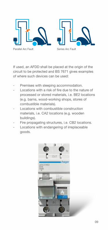
Series Arc FaultParallel Arc Fault
If used, an AFDD shall be placed at the origin of the circuit to be protected and BS 7671 gives examplesof where such devices can be used:
- Premises with sleeping accommodation. - Locations with a risk of fire due to the nature of
processed or stored materials, i.e. BE2 locations (e.g. barns, wood-working shops, stores of combustible materials).
- Locations with combustible construction materials, i.e. CA2 locations (e.g. wooden buildings).
- Fire propagating structures, i.e. CB2 locations. - Locations with endangering of irreplaceable
goods.
10
Previously the requirements to provide surge protection devices or not was rather complex, requiring the AQ classification as to the number of thunderstorm days likely at the location of the installation.
This has all been removed and the 18th Edition now requires protection against transient overvoltage to be provided where the consequence:-
- results in serious injury to, or loss of, human life, or; - results in interruption of public services/or
damage to and cultural heritage, or; - results in interruption of commercial or industrial
activity, or; - affects a large number of co-located individuals.
For other cases a risk assessment is required to be performed. Should a risk assessment not be performed then protection against transient overvoltage is required.
Single dwelling units however require an assessment as to whether the total value of the installation and equipment therein justifies the inclusion of such protection.
Protection Against Transient Overvoltages of Atmospheric Origin or Due to Switching (443.4)
11
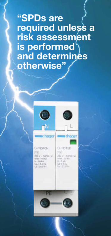
“SPDs are required unless a risk assessment is performed and determines otherwise”
12
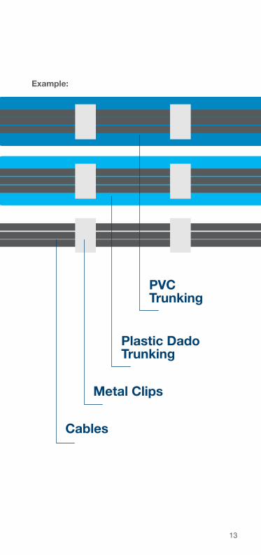
Supporting of Cables Against Premature Collapse (521.10.202)
Amendment 3 to the 17th Edition introduced a requirement whereby cables in escape routes should be supported against their premature collapse in the event of a fire. This was so that collapsed cables should not impede people escaping from; or indeed fire fighters entering a building on fire.
This has however caused some confusion as to what exactly is an escape route. The 18th Edition has therefore clarified this by removing the term ‘escape route’. It is therefore now a requirement that all wiring systems are supported such that they will not be liable to premature collapse in the event of a fire.
Suitably spaced steel or copper clips, saddles or ties are examples that will meet the requirements of this regulation.
“Wiring systems shall be supported against premature collapse in the event of a fire”
13
Metal Clips
Plastic DadoTrunking
Cables
PVCTrunking
Example:
14
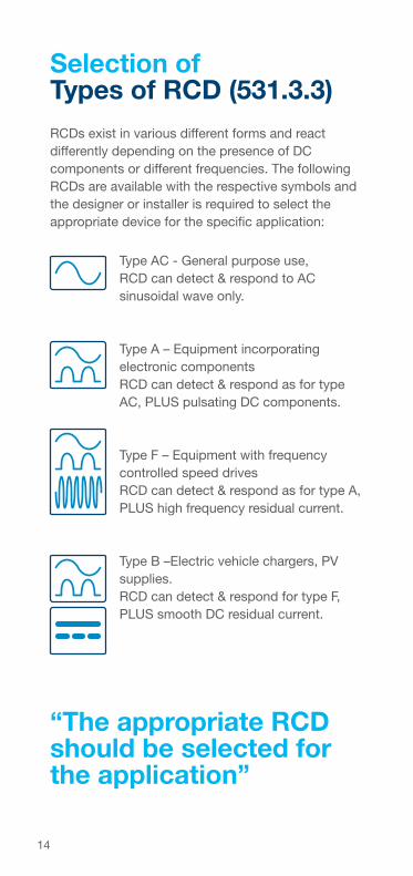
RCDs exist in various different forms and react differently depending on the presence of DC components or different frequencies. The following RCDs are available with the respective symbols and the designer or installer is required to select the appropriate device for the specific application:
Selection of Types of RCD (531.3.3)
“The appropriate RCD should be selected for the application”
Type AC - General purpose use, RCD can detect & respond to AC sinusoidal wave only.
Type A – Equipment incorporating electronic componentsRCD can detect & respond as for type AC, PLUS pulsating DC components.
Type F – Equipment with frequency controlled speed drivesRCD can detect & respond as for type A, PLUS high frequency residual current.
Type B –Electric vehicle chargers, PV supplies.RCD can detect & respond for type F, PLUS smooth DC residual current.
15
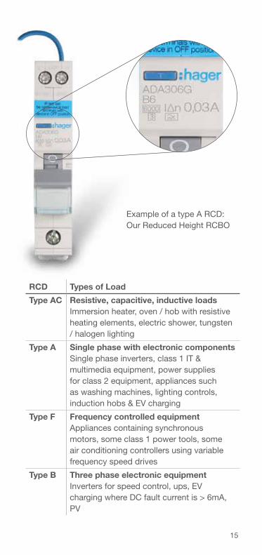
Example of a type A RCD:Our Reduced Height RCBO
RCD Types of Load
Type AC Resistive, capacitive, inductive loadsImmersion heater, oven / hob with resistive heating elements, electric shower, tungsten / halogen lighting
Type A Single phase with electronic componentsSingle phase inverters, class 1 IT & multimedia equipment, power supplies for class 2 equipment, appliances such as washing machines, lighting controls, induction hobs & EV charging
Type F Frequency controlled equipmentAppliances containing synchronous motors, some class 1 power tools, some air conditioning controllers using variable frequency speed drives
Type B Three phase electronic equipmentInverters for speed control, ups, EV charging where DC fault current is > 6mA, PV
16
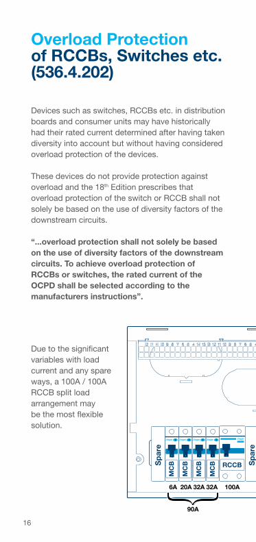
Devices such as switches, RCCBs etc. in distribution boards and consumer units may have historically had their rated current determined after having taken diversity into account but without having considered overload protection of the devices.
These devices do not provide protection against overload and the 18th Edition prescribes that overload protection of the switch or RCCB shall not solely be based on the use of diversity factors of the downstream circuits.
“...overload protection shall not solely be based on the use of diversity factors of the downstream circuits. To achieve overload protection of RCCBs or switches, the rated current of the OCPD shall be selected according to the manufacturers instructions”.
Overload Protection of RCCBs, Switches etc. (536.4.202)
Sw/D/I
MC
B
MC
B
MC
B
MC
B
MC
B
MC
B
MC
B
MC
B RCCBRCCBSp
are
Sp
are
Meter
005625.00
Service Cut-Out
100A 40A32A32A32A32A20A6A 6A 100A
100A
100A
90A 110A
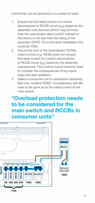
Due to the significant variables with load current and any spare ways, a 100A / 100A RCCB split load arrangement may be the most flexible solution.
17
“Overload protection needs to be considered for the main switch and RCCBs in consumer units”
Sw/D/I
MC
B
MC
B
MC
B
MC
B
MC
B
MC
B
MC
B
MC
B RCCBRCCBSp
are
Sp
are
Meter
005625.00
Service Cut-Out
100A 40A32A32A32A32A20A6A 6A 100A
100A
100A
90A 110A
Sw/D/I
MC
B
MC
B
MC
B
MC
B
MC
B
MC
B
MC
B
MC
B RCCBRCCBSp
are
Sp
are
Meter
005625.00
Service Cut-Out
100A 40A32A32A32A32A20A6A 6A 100A
100A
100A
90A 110A
Conformity can be achieved in a number of ways:
1. Ensure that the rated current of a switch disconnector or RCCB circuit (Inc) stated by the assembly manufacturer (which may be lower than the unenclosed rated current marked on the device is not less than the rating of the upstream OCPD. For a domestic installation this could be 100A.
2. Ensure the sum of the downstream OCPDs rated currents e.g. MCBs does not exceed the rated current of a switch disconnector or RCCB circuit (Inc) stated by the assembly manufacturer. This method would however need to consider the consequences of any spare ways and later additions.
3. Select a consumer unit or distribution assembly that only contains RCBO. Consideration will still need to be given as to the rated current of the main switch.
18
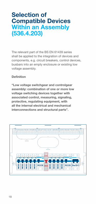
The relevant part of the BS EN 61439 series shall be applied to the integration of devices and components, e.g. circuit breakers, control devices, busbars into an empty enclosure or existing low voltage assembly.
Definition
“Low voltage switchgear and controlgear assembly: combination of one or more low voltage switching devices together with associated control, measuring, signaling, protective, regulating equipment, with all the internal electrical and mechanical interconnections and structural parts”.
Selection of Compatible Devices Within an Assembly(536.4.203)
Sw/D/I
MC
B
MC
B
MC
B
MC
B
MC
B
MC
B
MC
B
MC
B
MC
B RCCBRCCB MCB
19
“The distribution assembly should only contain devices declared by the assembly manufacturer as compatible”
Therefore in low voltage assemblies to the BS EN 61439 series, e.g. consumer units, distribution boards, incorporated devices and components shall only be those declared suitable according to the assembly manufacturer’s instructions or literature.
If the consumer unit, distribution board etc. deviates from its original manufacturer’s instructions, or includes components not included in the original verification, the person introducing the deviation becomes the original manufacturer with the corresponding obligations.

20
Come and chat to us Live!
With the release of the 18th Edition of the wiring regulations, Hager are here to field any questions you may have through our Regs Live campaign.
Throughout this year we will be on hand to talk to you about all things 18th Edition, whenever you need us.
‘Regs Live’ will feature at ELEX Shows, through our tech line and via our new automated chatbot service Reg. Find out more about our plans for Regs Live on our 18th Edition hub, hager.co.uk/18thedition.
21
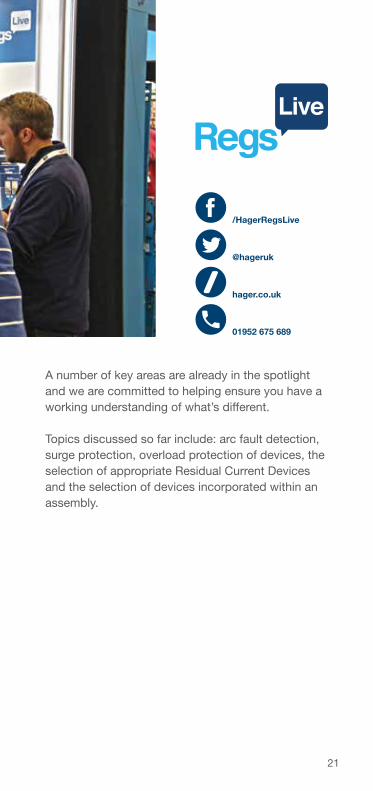
/HagerRegsLive
@hageruk
hager.co.uk
01952 675 689
A number of key areas are already in the spotlight and we are committed to helping ensure you have a working understanding of what’s different.
Topics discussed so far include: arc fault detection, surge protection, overload protection of devices, the selection of appropriate Residual Current Devices and the selection of devices incorporated within an assembly.

22
Notes

Notes

GUIDE18TH718 V2
Hager Ltd.Hortonwood 50TelfordShropshireTF1 7FT
Sales Service Centre: 01952 675612Technical Service Centre: 01952 675689
[email protected]@hager.co.uk
Hager Ltd. - IrelandUnit M2Furry Park Industrial EstateSwords RoadSantryDublin 9D09 NY19Ireland
Republic of Ireland Tel: 1890 551 502Republic of Ireland Fax: 1890 551 503Northern Ireland Tel: +44 (0)28 90021065Northern Ireland Fax: +353 (0)1 8869520