Embed Size (px)
Citation preview
geotechnics construction materials testing
90 Scarsdale road telephone: (905) 474-5265 Toronto, Ontario fax: (416) 444-3179 M3B 2R7 e-mail: [email protected]
Report Ref. No. 16-008 February 22, 2016
Prepared For: KINGSBERG DEVELOPMENT CORPORATION
340 FERRIER STREET, SUITE 8, MARKHAM, ON L3R 2Z5
ATTENTION: MR. PATRICK CHAN
Prepared By: Alston Associates Inc.
Distribution: Digital copy - KINGSBERG DEVELOPMENT CORPORATION
GEOTECHNICAL INVESTIGATION REPORT PROPOSED RESIDENTIAL DEVELOPMENT
1496 BAYLY STREET, PICKERING, ONTARIO

alston associates inc. Reference 16-008
February 22, 2016
GEOTECHNICAL INVESTIGATION REPORT PROPOSED RESIDENTIAL DEVELOPMENT 1496 BAYLY STREET, PICKERING, ON
i
CONTENTS 1 INTRODUCTION .................................................................................................................................. 1
2 FIELDWORK ......................................................................................................................................... 1
3 LABORATORY TESTS ............................................................................................................................ 2
4 SUBSURFACE CONDITIONS ............................................................................................................... 2
4.1 Site Description ...................................................................................................................................... 2 4.2 Topsoil ..................................................................................................................................................... 3 4.3 Fill ............................................................................................................................................................. 3 4.4 Native Soils ............................................................................................................................................. 3
4.4.1 Silty Clay .......................................................................................................................................3 4.4.2 Silty Sand ......................................................................................................................................3 4.4.3 Gravelly Sand ..............................................................................................................................4 4.4.4 Sandy Silt (Till) ...............................................................................................................................4 4.4.5 Shale Bedrock .............................................................................................................................5
4.5 Groundwater .......................................................................................................................................... 5 5 DISCUSSION AND RECOMMENDATIONS ......................................................................................... 5
5.1 Excavations, Groundwater Control and Backfill ................................................................................ 6 5.2 Foundation Design ................................................................................................................................. 7 5.3 Concrete Slab-on-Grade ..................................................................................................................... 8 5.4 Elevator Pits ............................................................................................................................................ 9 5.5 Lateral Earth Pressures ........................................................................................................................... 9 5.6 Shoring Design ..................................................................................................................................... 10 5.7 Pavement Design ................................................................................................................................ 12 5.8 Earthquake Design Parameters ......................................................................................................... 12 5.9 Chemical Characterization of Subsurface Soils ............................................................................... 12
6 LIMITATIONS OF REPORT .................................................................................................................. 13

alston associates inc. Reference 16-008
February 22, 2016
GEOTECHNICAL INVESTIGATION REPORT PROPOSED RESIDENTIAL DEVELOPMENT 1496 BAYLY STREET, PICKERING, ON
ii
APPENDICES .
APPENDIX A LIMITATIONS OF REPORT
APPENDIX B BOREHOLE LOCATION PLAN
APPENDIX C BOREHOLE LOG SHEETS
APPENDIX D LABORATORY TEST RESULTS
APPENDIX E CERTIFICATE OF CHEMICAL ANALYSIS
APPENDIX F RECOMMENDED PERIMETER DRAINAGE SYSTEM

alston associates inc. Reference 16-008
February 22, 2016
GEOTECHNICAL INVESTIGATION REPORT PROPOSED RESIDENTIAL DEVELOPMENT 1496 BAYLY STREET, PICKERING, ON
1
1 INTRODUCTION
Alston Associates Inc. (AAI) was retained by Kingsberg Development Corporation to carry out a geotechnical investigation for a proposed development located at 1496 Bayly Street in the City of Pickering, Ontario. Authorization to proceed with this study was given by Mr. Patrick Chan of Kingsberg Development Corporation.
We understand that Kingsberg Development Corporation is contemplating purchase of the site for redevelopment with a residential high-rise development with one or two basement levels which would extend to the property limits. In this regard, it is expected that shoring of the excavation walls will be required.
Four boreholes were advanced at the site to determine the subsurface soil and groundwater conditions, the relevant geotechnical properties of encountered soils and provide recommendations on the geotechnical aspects for the design of the foundations, subsurface structures, shoring system and the implementation of the project as outlined above.
This report presents the results of the investigation performed in accordance with the general terms of reference outlined above and is intended for the guidance of the client and the design architects and engineers only. It is assumed that the design will be in accordance with the applicable building codes and standards.
2 F IELDWORK
The fieldwork for this study was carried out during February 11 and 12, 2016 and included four (4) boreholes; Boreholes numbered BH1 through BH4, advanced near the four corners of the site. The locations of the boreholes are shown on the Borehole Location Plan enclosed in Appendix B of this report.
The boreholes were advanced to depths ranging from 9.3 to 13.8 m below ground surface (mbgs).
The ground surface elevations at the locations of the boreholes were referenced to the top of the fire hydrant located south of the southwest corner of the site. This benchmark was assigned an assumed elevation of 100.00 m.
Standard Penetration Tests (SPT) was carried out in the course of advancing the boreholes to take representative soil samples and to measure penetration index (N-values) to characterize the condition of the various soil materials. The number of blows of the striking hammer required to drive the split spoon sampler to 300 mm depth was recorded and these are presented on the borehole log sheets as penetration index values (N-values). Results of the SPT are shown on the borehole logs enclosed in Appendix C.
A field vane test (FVT) was carried out in the clay soil in one of the boreholes. The FVT provided an in situ measurement of the undrained shear strength of the clay soil unit.
Groundwater observations were made in the open boreholes during drilling and immediately after completion of drilling of the boreholes. The results of the groundwater measurements are discussed in Section 4.5 of this report.
alston associates inc. Reference 16-008
February 22, 2016
GEOTECHNICAL INVESTIGATION REPORT PROPOSED RESIDENTIAL DEVELOPMENT 1496 BAYLY STREET, PICKERING, ON
2
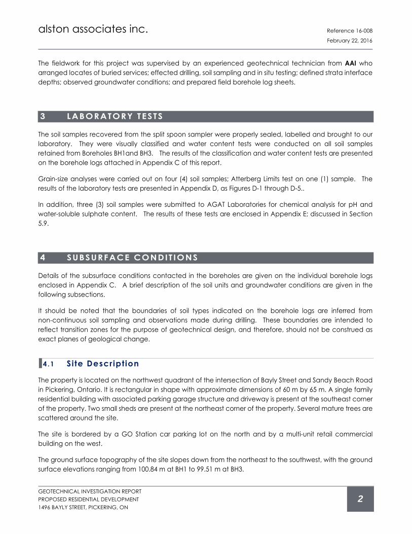
The fieldwork for this project was supervised by an experienced geotechnical technician from AAI who arranged locates of buried services; effected drilling, soil sampling and in situ testing; defined strata interface depths; observed groundwater conditions; and prepared field borehole log sheets.
3 LABORATORY TESTS
The soil samples recovered from the split spoon sampler were properly sealed, labelled and brought to our laboratory. They were visually classified and water content tests were conducted on all soil samples retained from Boreholes BH1and BH3. The results of the classification and water content tests are presented on the borehole logs attached in Appendix C of this report.
Grain-size analyses were carried out on four (4) soil samples; Atterberg Limits test on one (1) sample. The results of the laboratory tests are presented in Appendix D, as Figures D-1 through D-5..
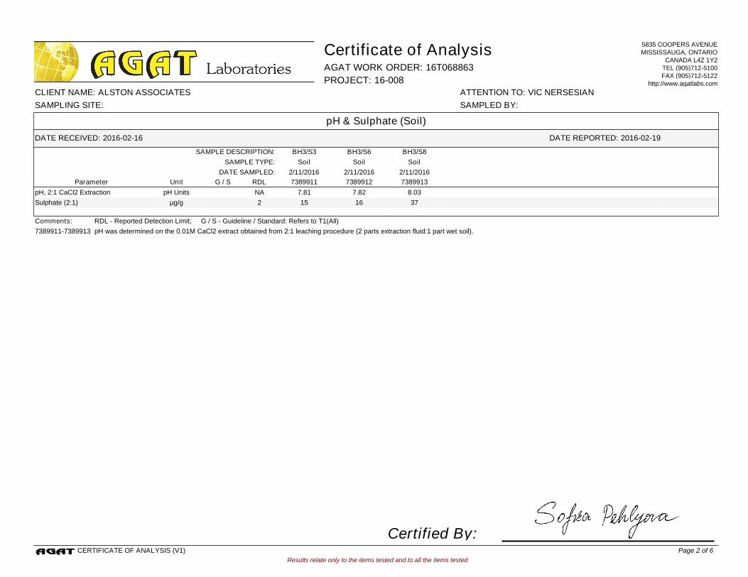
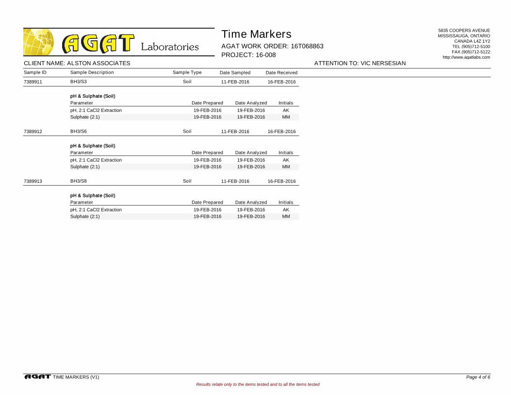
In addition, three (3) soil samples were submitted to AGAT Laboratories for chemical analysis for pH and water-soluble sulphate content. The results of these tests are enclosed in Appendix E; discussed in Section 5.9.
4 SUBSURFACE CONDIT IONS
Details of the subsurface conditions contacted in the boreholes are given on the individual borehole logs enclosed in Appendix C. A brief description of the soil units and groundwater conditions are given in the following subsections.
It should be noted that the boundaries of soil types indicated on the borehole logs are inferred from non-continuous soil sampling and observations made during drilling. These boundaries are intended to reflect transition zones for the purpose of geotechnical design, and therefore, should not be construed as exact planes of geological change.
4.1 Site Descript ion
The property is located on the northwest quadrant of the intersection of Bayly Street and Sandy Beach Road in Pickering, Ontario. It is rectangular in shape with approximate dimensions of 60 m by 65 m. A single family residential building with associated parking garage structure and driveway is present at the southeast corner of the property. Two small sheds are present at the northeast corner of the property. Several mature trees are scattered around the site.
The site is bordered by a GO Station car parking lot on the north and by a multi-unit retail commercial building on the west.
The ground surface topography of the site slopes down from the northeast to the southwest, with the ground surface elevations ranging from 100.84 m at BH1 to 99.51 m at BH3.

alston associates inc. Reference 16-008
February 22, 2016
GEOTECHNICAL INVESTIGATION REPORT PROPOSED RESIDENTIAL DEVELOPMENT 1496 BAYLY STREET, PICKERING, ON
3
4.2 Topsoi l
Approximately 220 to 280 mm thick layer of topsoil is present at the locations of the boreholes.
4.3 Fi l l
A thin layer of silty sand fill, approximately 300 mm thick is present below the topsoil at BH3. We were advised that a septic bed is present near the southwest corner of the site. It is likely that the sand fill is associated with the septic bed, and a thicker layer of sand is likely present within the septic bed.
The sand is loose; N-value of 5.
Fill is not present in any of the other boreholes.
4.4 Native Soi ls
4.4 .1 S i l ty Clay
A deposit of silty clay is present in the boreholes below the topsoil and the silty sand fill in BH3. The silty clay soil is coloured brownish grey at shallow depths turning to grey below approximate depths of 1 to 3 mbgs. The silty clay is layered and locally parted with silt seams. It extends to depths ranging from 3.5 to 5 mbgs.
Penetration resistance in the silty clay soil measured N-values ranging from 17 to 0, indicating stiff to very soft consistencies. The consistency of the silty clay is generally stiff to firm within the upper subzone of the soil unit becoming very soft below depths of 2 to 4 mbgs.
Sieve and hydrometer grain size analyses were carried out on one (1) sample of the silty clay soil obtained from Borehole BH3 at 2.5 mbgs (Sample 4). The test revealed that the soil has 0% gravel, 1% sand, 71% silt and 28% clay. The grain size analyses results are shown as Figure D-1 in Appendix D. Based on results of the grain size analysis, the Coefficient of Permeability (k) of the silty clay soil is estimated to be less than 10-8 cm/sec; very low permeability.
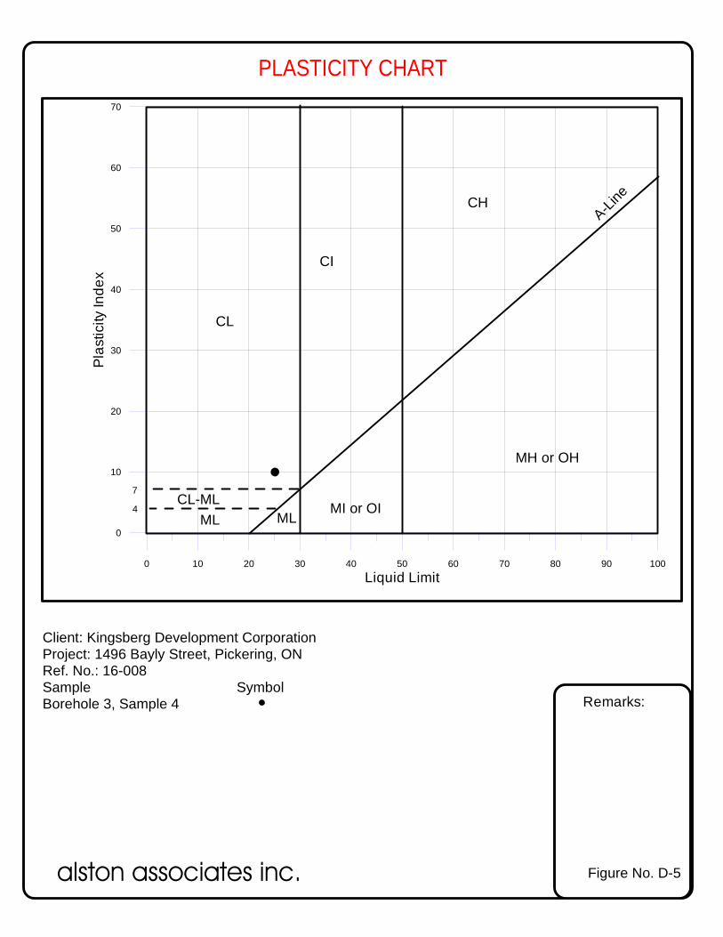
Atterberg Limits test carried out on the silty clay soil revealed that the Liquid Limit of the soil is approximately 26, the Plasticity Index is 10. Using the plasticity diagram as shown on Figure 3.1 of the Canadian Foundation Engineering manual, 4th Edition, the clay fill is classified as “inorganic clays of low plasticity”. The laboratory test results are shown on Figure D-5 enclosed in Appendix D.
FVT was carried out in Borehole BH1 at a depth of 3 mbgs within the softer sub zone of the unit. The measured undrained shear strength (Su) is 70 kPa. This Su value corresponds to stiff consistency according to Table 3.3 of the Canadian Foundation Engineering manual (CFEM), 4th Edition.
The water content of the silty clay samples range from about 17 to 31% by weight.
4 .4 .2 S i l ty Sand
A deposit of silty sand containing some gravel and trace of clay is present below the silty clay unit extending

alston associates inc. Reference 16-008
February 22, 2016
GEOTECHNICAL INVESTIGATION REPORT PROPOSED RESIDENTIAL DEVELOPMENT 1496 BAYLY STREET, PICKERING, ON
4
between approximate depths of 3.5 and 5.5 mbgs at Boreholes BH1 and BH2, between approximate depths of 5 and 7.5 mbgs at BH3, and between approximate depths of 4 and 5.5 mbgs at BH4. The silty sand unit is coloured grey and is generally wet in appearance.
Penetration resistance in the silty sand soil measured N-values of 14 to 0 blows, indicating a compact to loose compactness condition. It is possible that the very low N-values obtained in this soil unit are due to the upward hydrostatic pressure at the bottom of the borehole immediately prior to the Standard Penetration Tests.
Sieve and hydrometer grain size analyses were carried out on one (1) sample of the silty sand soil obtained from Borehole BH3 at 6 mbgs (Sample 7). The test revealed that the soil consists of 13% gravel, 52% sand, 29% silt and 6% clay. The grain size analyses results are shown as Figure D-2 in Appendix D.
Based on the results of the grain size analysis, the Coefficient of Permeability (k) of the silt to clayey silt soil is estimated to be approximately 2.5X10⁻⁵ cm/s.
The water content of the silt to clayey silt samples is about 9 to 11% by weight.
4 .4 .3 Gravel ly Sand
An approximately 2 m thick layer of gravelly sand is present in Boreholes BH1 and BH4 extending between approximate depths of 5.5 to 7.5 mbgs.
The gravelly sand unit is coloured grey and is generally wet in appearance.
Penetration resistance in the gravelly sand soil measured N-values of 38 and 55, indicating generally a dense compactness condition.
Grain size analysis was carried out on one (1) sample of gravelly sand soil obtained from Borehole BH1 at 6.6 mbgs (Sample 8). The test revealed that the soil has 12% gravel, 85% sand, and 3% silt and clay. The grain size analysis results are shown as Figure D-3 in Appendix D.
Based on the results of the grain size analysis, the Coefficient of Permeability (k) of the gravelly sand soil is estimated to be 4x10⁻² cm/sec; very high permeability.
The water content of the silt to clayey silt samples is about 12 to 17% by weight.
4 .4 .4 Sandy S i l t (T i l l )
Below the wet, dense gravelly sand unit in Boreholes BH1 and BH4, and the silty sand unit in Boreholes BH2 and BH3, a glacial till deposit consisting of predominantly sandy silt, with some clay and gravel is present. Cobbles and boulders are probably present within this soil stratum but would not be representatively sampled with the equipment used in this investigation.
The sandy silt (till) is grey in colour and moist to dry in appearance.
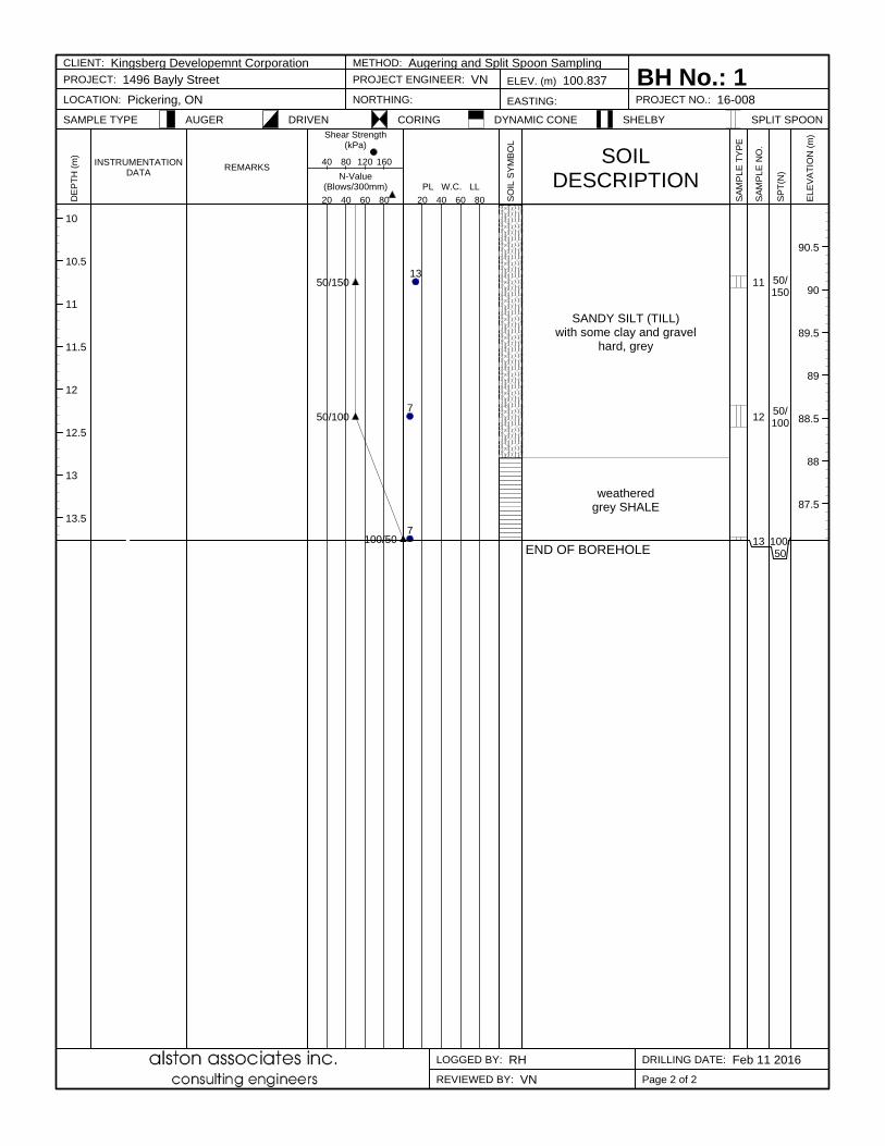
SPT carried out in the sandy silt (till) provided N-value of 41 blows above a depth of 7.5 mbgs in BH2, and in excess of 100 blows below a depth of 7.5 m in all four boreholes.
alston associates inc. Reference 16-008
February 22, 2016
GEOTECHNICAL INVESTIGATION REPORT PROPOSED RESIDENTIAL DEVELOPMENT 1496 BAYLY STREET, PICKERING, ON
5
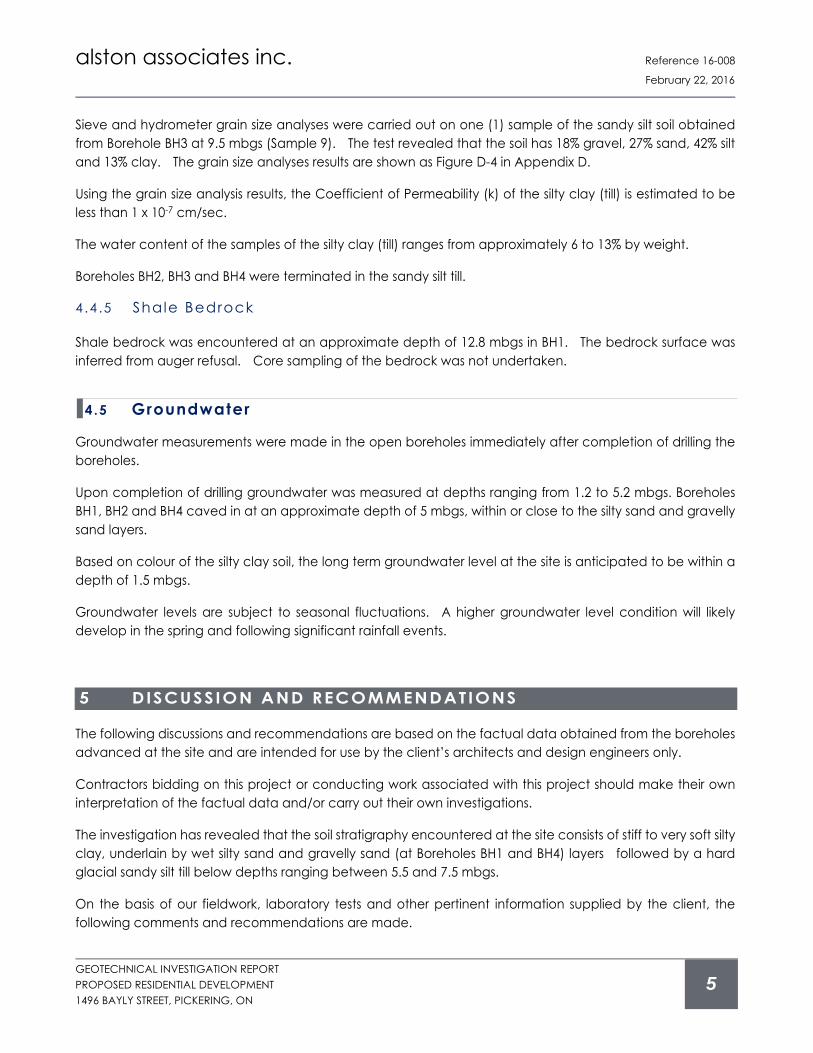
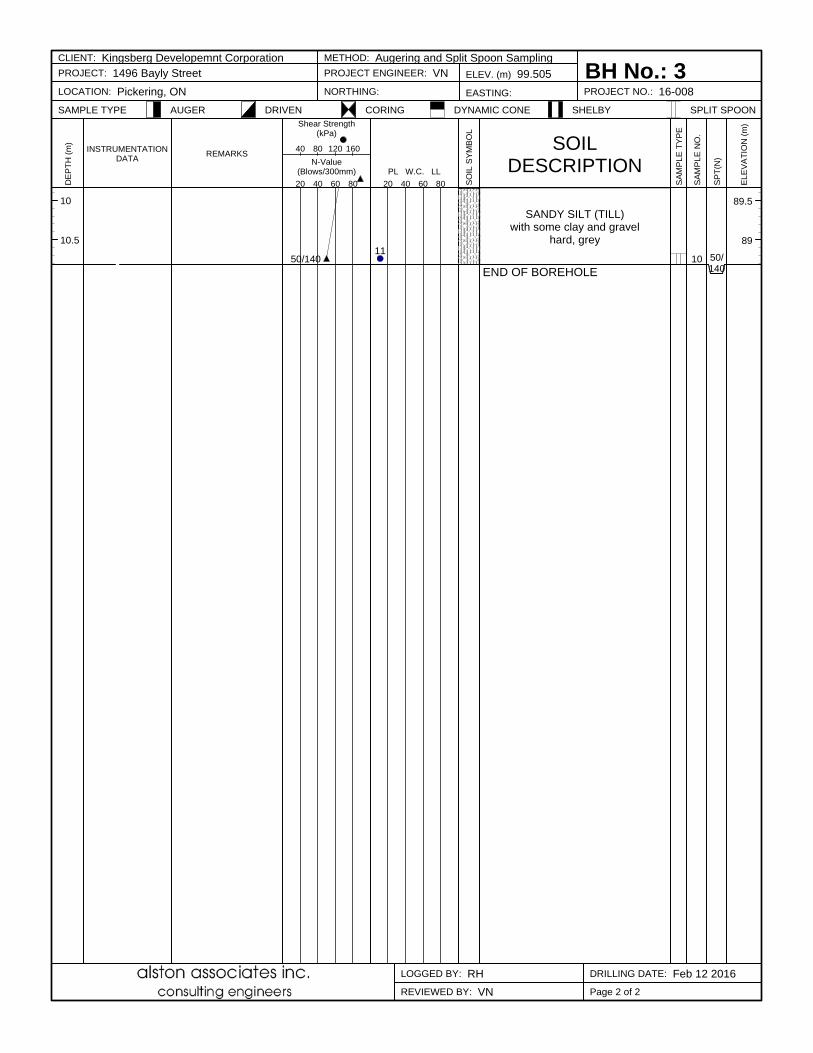
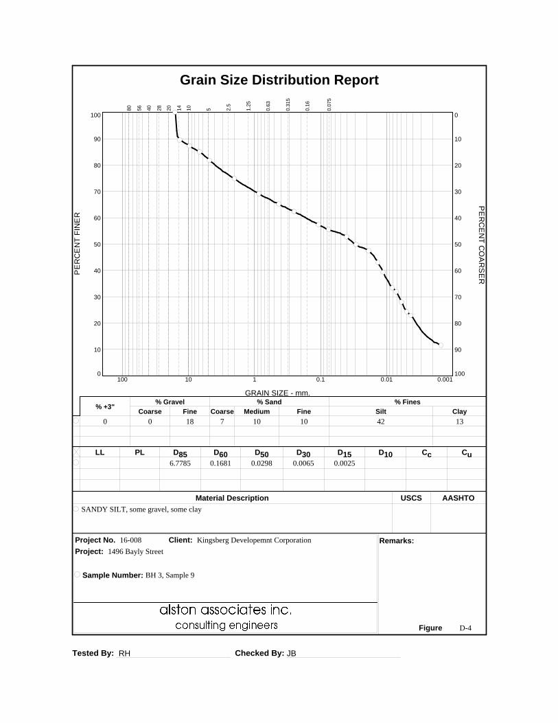
Sieve and hydrometer grain size analyses were carried out on one (1) sample of the sandy silt soil obtained from Borehole BH3 at 9.5 mbgs (Sample 9). The test revealed that the soil has 18% gravel, 27% sand, 42% silt and 13% clay. The grain size analyses results are shown as Figure D-4 in Appendix D.
Using the grain size analysis results, the Coefficient of Permeability (k) of the silty clay (till) is estimated to be less than 1 x 10⁻⁷ cm/sec.
The water content of the samples of the silty clay (till) ranges from approximately 6 to 13% by weight.
Boreholes BH2, BH3 and BH4 were terminated in the sandy silt till.
4 .4 .5 Shale Bedrock
Shale bedrock was encountered at an approximate depth of 12.8 mbgs in BH1. The bedrock surface was inferred from auger refusal. Core sampling of the bedrock was not undertaken.
4.5 Groundwater
Groundwater measurements were made in the open boreholes immediately after completion of drilling the boreholes.
Upon completion of drilling groundwater was measured at depths ranging from 1.2 to 5.2 mbgs. Boreholes BH1, BH2 and BH4 caved in at an approximate depth of 5 mbgs, within or close to the silty sand and gravelly sand layers.
Based on colour of the silty clay soil, the long term groundwater level at the site is anticipated to be within a depth of 1.5 mbgs.
Groundwater levels are subject to seasonal fluctuations. A higher groundwater level condition will likely develop in the spring and following significant rainfall events.
5 DISCUSSION AND RECOMMENDATIONS
The following discussions and recommendations are based on the factual data obtained from the boreholes advanced at the site and are intended for use by the client’s architects and design engineers only.
Contractors bidding on this project or conducting work associated with this project should make their own interpretation of the factual data and/or carry out their own investigations.
The investigation has revealed that the soil stratigraphy encountered at the site consists of stiff to very soft silty clay, underlain by wet silty sand and gravelly sand (at Boreholes BH1 and BH4) layers followed by a hard glacial sandy silt till below depths ranging between 5.5 and 7.5 mbgs.
On the basis of our fieldwork, laboratory tests and other pertinent information supplied by the client, the following comments and recommendations are made.

alston associates inc. Reference 16-008
February 22, 2016
GEOTECHNICAL INVESTIGATION REPORT PROPOSED RESIDENTIAL DEVELOPMENT 1496 BAYLY STREET, PICKERING, ON
6
5.1 Excavations, Groundwater Control and Backfi l l
Based on the field results, excavations for basement and foundations are not expected to pose any unusual difficulty. Excavation of the soils at this site can be carried out with heavy hydraulic excavators.
All excavations must be carried out in accordance with Occupational Health and Safety Act (OHSA). With respect to OHSA, the stiff to soft silty clay soils are expected to conform to Type 3 soil classification. The silty sand and gravelly sand soils are classified as Type 4 soil.
Temporary excavations for slopes in Type 3 soil should not exceed 1.0 horizontal to 1.0 vertical or flatter. Side slopes of excavations extended into the wet sandy soils should not be steeper than 3 horizontal to 1 vertical.
In the event very loose and/or soft soils are encountered at shallow depths or within zones of persistent seepage, it will be necessary to flatten the side slopes as necessary to achieve stable conditions.
For excavations through multiple soil types, the side slope geometry is governed by the soil with the highest number designation. Excavation side-slopes should not be unduly left exposed to inclement weather.
Where workers must enter excavations extending deeper than 1.2 m below grade, the excavation side-walls must be suitably sloped and/or braced in accordance with the Occupational Health and Safety Act and Regulations for Construction Projects.
It should be noted that the till soils are non-sorted sediments and therefore may contain boulders. Provisions should be made in the excavation contract for the removal of possible boulders.
The on-site silty clay soil is excessively wetter than its optimum moisture content. This material will prove difficult to compact and should be dried sufficiently in order to achieve the specified degree of compaction.
It is understood that the proposed building will be constructed on either a single or two levels of underground parking garage. It is expected that for single level basement construction the basement floor will be positioned at about 3 m below existing grade; 6 mbgs for two levels basement. The subsurface soil profiles would consists of stiff to very soft silty clay overlying silty sand, gravelly sand and sandy silt till below depths ranging from approximately 5.5 to 7.5 mbgs.
The boreholes advanced at the site revealed that groundwater is positioned at shallow depths below existing grade; at about 1.5 to 2 mbgs. The groundwater yield from the silty clay unit is expected to be very small; however moderate to significant water seepage is expected through the silty sand and gravelly sand unit below approximate depths of 3.5 to 7.5 mbgs. In this regard, in the event that the excavation will extend below the wet sandy soils (for two basement levels), it is recommended to install a tangent pile (caisson) wall along the perimeter of the excavation of the proposed underground garages, in order to prevent ingress of groundwater into the excavation.
In order to control seepage flow into the excavation, the caisson wall should extend below the lowest excavation depth with sufficient penetration into the sandy silt till soil; below the water bearing gravelly sand soils such that groundwater seepage into the excavation can be cut-off and groundwater will be dewatered from inside the excavation.

alston associates inc. Reference 16-008
February 22, 2016
GEOTECHNICAL INVESTIGATION REPORT PROPOSED RESIDENTIAL DEVELOPMENT 1496 BAYLY STREET, PICKERING, ON
7
A Permit to Take Water (PTTW) should not be necessary in the event that dewatering is carried out from within the caisson wall enclosure.
Assuming that the exterior basement walls of the proposed development will be poured up against the shored sides of the excavations, prefabricated drainage sheets (Terradrain 600 or equivalent) must be placed continuously against the walls. These should drain through drainage ports in the walls into a perimeter solid pipe and channel all the water into a sump pit in the building. The maximum spacing of the drainage ports must not exceed 6 m, subject to confirmation at the time of construction.
Sub-floor weeping pipes 100 mm in diameter must be placed under the lowest basement floor at a maximum spacing of 8 m (subject to confirmation at the time of construction). The weeping tiles must be wrapped with filter fabric and covered with a minimum of 150 mm of clear stone. They should be placed a minimum depth of 0.5 m below the basement floor slab, above the founding level of the footings.
The perimeter and sub-floor drains must be connected to a positive frost free outlet from which the water can be removed, or connected to a sump located in the lowest level of the basement. The water from the sump must be pumped out to a suitable discharge point.
Typical details of perimeter drainage system are included in Appendix F of this report.
The installation of the perimeter and sub-floor drains as well as the outlet must conform to the applicable plumbing code requirements.
5.2 Foundation Design
The proposed development will include a single or two underground levels. It is expected that the garage floor slab would be situated at about 3 m below existing grade for single level underground parking; 6 m for two levels underground parking.
For a two level basement, it will be possible to use conventional spread and strip footings to support the proposed building. The footings should be founded in the hard sandy silt till encountered in the boreholes below depths ranging between 5.5 m and 7.5 mbgs, designed for bearing resistance at Serviceability Limit States (SLS) of 1000 kPa, and a factored geotechnical bearing resistance at Ultimate Limit States (ULS) of 1500 kPa, for vertical and centric loads.
The boreholes revealed that, at a nominal depth of 1.5 m below the single level garage floor; at an approximate depth of 4.5 mbgs, the clay and silty sand soils are too soft/loose and incapable of supporting the anticipated loads of the proposed building.
In this regard, for a single level basement, it is recommended to support the building on a deep foundation system using drilled piers (caissons). The drilled piers should extend at least 1 m into the hard sandy silt (till); designed for end bearing, with a bearing resistance at Serviceability Limit States (SLS) of I.5 MPa; factored geotechnical bearing resistance at Ultimate Limit States (ULS) of 1.8 MPa.
Based on the borehole findings, the drilled piers should be founded at an approximate depth of 8.5 mbgs.

alston associates inc. Reference 16-008
February 22, 2016
GEOTECHNICAL INVESTIGATION REPORT PROPOSED RESIDENTIAL DEVELOPMENT 1496 BAYLY STREET, PICKERING, ON
8
Shaft resistance (adhesion) developed from the drilled piers and the surrounding soils may be utilized to increase the foundation (caisson) capacity. The recommended shaft resistances for various soil units are given below.
Soil Unit Allowable Shaft Friction at SLS (kPa) Allowable Shaft Friction at ULS (kPa)
Dense gravelly sand 50 75
Hard Sandy Silt (Till) 100 150
It will be necessary to install temporary liners during the drilling of the caisson holes; to prevent ingress of groundwater seepage as well as caving of the wet sandy soils during the drilling of the caisson holes. Furthermore, it will be necessary to pour concrete in the drilled holes immediately after drilling to prevent accumulation of groundwater in the drilled holes. The temporary liners should be withdrawn in such a manner that there is sufficient head of concrete to prevent water and soils ingress into the caisson holes.
The geotechnical bearing resistance values recommended above are for vertical loads (no inclination) and no eccentricity. The total and differential settlements of foundations designed in accordance with the recommendations provided in this report should not exceed the conventional limits of 25 mm and 19 mm respectively.
Due to variations in the consistency of the founding soils and/or softening caused by excavation disturbance and/or seasonal frost effects, all foundation subgrade must be evaluated by the Geotechnical Engineer prior to placing foundation concrete to ensure that the soil exposed at the excavation base is consistent with the design geotechnical bearing resistance.
AAI recommends that shallow footings placed on the exposed native soil should be poured on the same day as they are excavated, after removal of all unsuitable founding materials and approval of the bearing surface. Alternatively, a concrete mud slab could be used to protect a bearing surface where footing construction is to be delayed.
If construction proceeds during freezing weather conditions, adequate temporary frost protection for the footing bases and foundation concrete must be provided.
Rainwater or groundwater seepage entering the foundation excavation must be pumped away (not allowed to pond). The foundation subgrade soils should be protected from freezing, inundation and equipment traffic at all times.
5.3 Concrete Slab-on-Grade
The subgrade at the basement floor slab should consist of native soils which are capable of supporting slab-on-grade construction. The subgrade soils are anticipated to comprise of firm to soft silty clay for single level basement construction; silty sand, gravelly sand and sandy silt till for two levels basement. Subgrade preparation should include the removal of any weak, softened and disturbed soils. After removal of all unsuitable materials, the subgrade should then be proof-rolled with heavy rubber tired equipment. The proof-rolling operation should be witnessed by the Geotechnical Engineer. Any soft or wet subgrade areas

alston associates inc. Reference 16-008
February 22, 2016
GEOTECHNICAL INVESTIGATION REPORT PROPOSED RESIDENTIAL DEVELOPMENT 1496 BAYLY STREET, PICKERING, ON
9
which deflect significantly should be sub-excavated and replaced with suitable approved earth fill material compacted to at least 98% of Standard Proctor Maximum Dry Density (SPMDD).
Where the subgrade soil is very soft (for a single level basement) it may be necessary to replace the uppermost minimum 300 mm thick layer of the soft silty clay with 50 mm crusher run limestone to provide a working platform for construction traffic.
It is recommended that a combined moisture barrier and a levelling course, having a minimum thickness of 200 mm and comprised of free draining material consisting of 19 mm clear stone (OPSS 1004) underlain by filter fabric separating the clear stone and the subgrade soils, be used as base for the slab-on-grade. The clear stone base must be compacted by vibration to a dense state.
Provided the subgrade, under-floor fill and granular base are prepared in accordance with the above recommendations, the Modulus of Subgrade Reaction (ks) for floor slab design will be 25,000 kPa/m.
The soils at this site are susceptible to frost effects which would have the potential to deform hard landscaping adjacent to the building. At locations where proposed building are expected to have flush entrances, care must be taken in detailing the exterior slabs / sidewalks, providing insulation / drainage / non-frost susceptible backfill to maintain the flush threshold during freezing weather conditions.
5.4 Elevator Pi ts
Elevator pit(s) in general are constructed at a minimum depth of 1.5 m below the lowest basement floor slab, approximately 4.5 to 5 m below existing grade for single level basement; 7.5 to 8 m for two levels basement.
Given that groundwater will be encountered at the anticipated depths, it is recommended to waterproof the bases and the walls of the elevator pits, and design the pit for hydrostatic uplift and lateral pressures.
5.5 Lateral Earth Pressures
Parameters used in the determination of earth pressure acting on temporary shoring walls are defined below.
Soil Parameters
Parameter Definition Units
Φ’ angle of internal friction degrees γ bulk unit weight of soil kN/m3
Ka active earth pressure coefficient (Rankine) dimensionless
Ko at-rest earth pressure coefficient (Rankine) dimensionless
Kp passive earth pressure coefficient (Rankine) dimensionless
The appropriate un-factored values for use in the design of structures subject to unbalanced earth pressures at this site are tabulated as follows:

alston associates inc. Reference 16-008
February 22, 2016
GEOTECHNICAL INVESTIGATION REPORT PROPOSED RESIDENTIAL DEVELOPMENT 1496 BAYLY STREET, PICKERING, ON
10
Soil Parameter Values
Soil Parameter
Φ’ γ Ka Kp K0
Silty Clay 28° 19 0.36 2.77 0.53
Silty Sand 28° 20 0.36 2.77 0.53
Gravelly Sand 35° 21.5 0.27 3.70 0.43
Sandy Silt (Till) 32° 22.5 0.31 3.22 0.47
Subsurface walls that are subject to unbalanced earth and hydrostatic pressures must be designed to resist a pressure that can be calculated based on the following formula:
P = K [ (h – hw) + 'hw + q] + whw
where P = lateral pressure in kPa acting at a depth h (m) below ground surface K = applicable lateral earth pressure coefficient (Use K0 for basement wall design)
H = height at any point along the interface (m) hw = depth below the groundwater level at point of interest (m) = bulk unit weight of backfill (kN/m3) ’ = the submerged unit weight (kN/m3) of exterior soil (' = - w) w = unit weight of water, assume a value of 9.8 kN/m3 q = the complete surcharge loading (kPa)
Resistance to sliding of earth retaining structures is developed by friction between the base of the footing and the soil. This friction (R) depends on the normal load on the soil contact (N) and the frictional resistance of the soil (tan Φ’) expressed as: R = N tan Φ’. This is an ultimate resistance value and does not contain a factor of safety.
5.6 Shoring Design
Due to the presence of water bearing silty sand and gravelly sand layers, for a two level basement it is recommended to install a tangent pile (caisson) wall as the shoring system. For a single level basement a soldier pile and lagging system should suffice.
The design of temporary shoring for the support of the excavation walls must account for the presence of structures and buried services on the adjacent properties, and the existing subsurface conditions at the site.
The lateral restraining force for the shoring system may be provided by employing either rakers or tieback anchors. The latter is favorable because they do not protrude into the excavations as is the case with rakers. The use of tieback anchors will depend on whether permission is obtained to extend the anchors to the required distance on to the neighboring properties.
To prevent possible caving of soils, the tieback anchors should be drilled with a hollow stem auger, and anchors installed and concrete/cement grout poured through the liner.

alston associates inc. Reference 16-008
February 22, 2016
GEOTECHNICAL INVESTIGATION REPORT PROPOSED RESIDENTIAL DEVELOPMENT 1496 BAYLY STREET, PICKERING, ON
11
Temporary liners must be used for excavation of the tangent pile holes. The shoring contractor should also provide construction method(s) to overcome any groundwater seepage into the pile holes during excavation and subsequent concreting of the drilled holes to comply with good construction practice.
The shoring design should be based on the procedure detailed in the latest edition of the CFEM.
The earth pressure coefficients applicable for the design of the shoring system are:
= Ka the active pressure coefficient, applicable where small movements may be tolerated in the retained soil, = 0.3.
= Ko the ‘at rest’ earth pressure coefficient, applicable where no movement in the retained soil can be permitted, such as the presence of buried services or foundations close to the wall, = 0.45.
Based on the borehole findings, excavation for basement is anticipated to terminate in the native silty clay. The minimum depth of penetration (d) of soldier piles may be estimated from the following expression:
R = NB (½d2Kp)
where R = required toe resistance
Kp = passive earth pressure coefficient
N = factor according to three dimensional effect around an isolated pile, use 2.0
B = diameter of concrete filled hole
d = required penetration depth
= bulk unit weight of soil
Raker footings should be designed in accordance with the design principals for shallow foundations subject to inclined loading. All raker footings should be located outside the zone of influence of the buried portion of soldier piles, and at a distance of no less than 1.5D from the piles, where D = Depth of penetration of the piles below the base of the excavation. No excavation should be made within two footings widths of the raker footings, on the side opposite the rakers.
The length providing effective anchorage for tie-back anchors is that extending beyond a line projected up at a 45o from the toe of excavation.
Anchors extended into soft silty clay may be designed based on soil/grout bond value of 10 kPa; 50 KPa into the dense gravelly sand and 80 kPa for the hard sandy silt till. These values depend on the anchor installation method and grouting procedures. Gravity poured concrete can result in low bond values, while pressure grouted anchors will give higher values and produce a more satisfactory anchor.
It will be necessary to perform load tests on the tiebacks to confirm the bond stresses assumed in the design of anchors.
Movement of the shoring system is inevitable. Vertical movements will result from the vertical loads on the soldier piles resulting from the inclined tiebacks and inward horizontal movement will result from the earth and water pressures. The magnitude of this movement can be controlled by sound construction practices.
alston associates inc. Reference 16-008
February 22, 2016
GEOTECHNICAL INVESTIGATION REPORT PROPOSED RESIDENTIAL DEVELOPMENT 1496 BAYLY STREET, PICKERING, ON
12
The lateral and vertical movement of the shoring system must be monitored especially at locations in which settlement sensitive structures are present, to ensure that movements are kept within acceptable range.
5.7 Pavement Design
The pavement above the parking garage roof slab may be comprised of a minimum of 75 mm thick layer of granular ‘A’ topped with asphaltic concrete having a minimum thickness of 80 mm (40 mm HL8 and 40 mm HL3). The asphaltic concrete materials should be rolled and compacted in accordance with OPSS 310 requirements.
The gradation and physical properties of HL-3 and HL-8 asphaltic concrete, and Granular ‘A’ shall conform to the OPSS standards.
The critical section of pavement will be at the transition between the pavement on grade and the pavement above the garage roof slab. In order to alleviate the detrimental effects of dynamic loading / settlement / pavement depression in the backfill to the rigid garage roof structure, it is recommended that an approach type slab be constructed at the entrance/exit points, by extending the granular sub-base to greater depths along the exterior garage wall.
5.8 Earthquake Design Parameters
The 2012 Ontario Building Code (OBC) stipulates the methodology for earthquake design analysis, as set out in Subsection 4.18.7. The determination of the type of analysis is predicated on the importance of the structure, the spectral response acceleration and the site classification.
The parameters for determination of the Site Classification for Seismic Site Response are set out in Table 4.1.8.4.A of the 2012 OBC. The classification is based on the determination of the average shear wave velocity in the top 30 metres of the site stratigraphy, where shear wave velocity (Vs) measurements have been taken. In the absence of such measurements, the classification is estimated on the basis of empirical analysis of undrained shear strength or penetration resistance. The applicable penetration resistance is that which has been corrected to a rod energy efficiency of 60% of the theoretical maximum or the (N60) value.
Based on the borehole information, the subsurface stratigraphy as revealed in the boreholes generally comprises stiff to soft silty clay, underlain by loose to compact silty sand, dense gravelly sand, hard sandy silt till followed by shale bedrock at an approximate depth of 13 mbgs. On this basis, the site designation for seismic analysis is Class C according to Table 4.1.8.4.A from the quoted code.
The site specific 5% damped spectral acceleration coefficients, and the peak ground acceleration factors are provided in the 2012 OBC - Supplementary Standard SB-1 (September 14, 2012), Table 1.2, location Pickering, Ontario.
5.9 Chemical Characterizat ion of Subsurface Soi ls
Three soil samples were subjected to pH and sulphate content tests to determine the potential of sulphate

alston associates inc. Reference 16-008
February 22, 2016
GEOTECHNICAL INVESTIGATION REPORT PROPOSED RESIDENTIAL DEVELOPMENT 1496 BAYLY STREET, PICKERING, ON
APPENDIX A LIMITATIONS OF REPORT

alston associates inc. Reference 16-008
February 22, 2016
GEOTECHNICAL INVESTIGATION REPORT PROPOSED RESIDENTIAL DEVELOPMENT 1496 BAYLY STREET, PICKERING, ON
Limitat ions of Report
The conclusions and recommendations in this report are based on information determined at the inspection locations. Soil and groundwater conditions between and beyond the test holes may differ from those encountered at the test hole locations, and conditions may become apparent during construction which could not be detected or anticipated at the time of the soil investigation.
The design recommendations given in this report are applicable only to the project described in the text, and then only if constructed substantially in accordance with details of alignment and elevations stated in the report. Since all details of the design may not be known to us, in our analysis certain assumptions had to be made as set out in this report. The actual conditions may, however, vary from those assumed, in which case changes and modifications may be required to our recommendations.
This report was prepared for Kingsberg Development Corporation by Alston Associates Inc. The material in it reflects Alston Associates Inc. judgement in light of the information available to it at the time of preparation. Any use which a Third Party makes of this report, or any reliance on decisions which the Third Party may make based on it, are the sole responsibility of such Third Parties.
We recommend, therefore, that we be retained during the final design stage to review the design drawings and to verify that they are consistent with our recommendations or the assumptions made in our analysis. We recommend also that we be retained during construction to confirm that the subsurface conditions throughout the site do not deviate materially from those encountered in the test holes. In cases where these recommendations are not followed, the company’s responsibility is limited to accurately interpreting the conditions encountered at the test holes, only.
The comments given in this report on potential construction problems and possible methods are intended for the guidance of the design engineer, only. The number of inspection locations may not be sufficient to determine all the factors that may affect construction methods and costs. The contractors bidding on this project or undertaking the construction should, therefore, make their own interpretation of the factual information presented and draw their own conclusions as to how the subsurface conditions may affect their work.

alston associates inc. Reference 16-008
February 22, 2016
GEOTECHNICAL INVESTIGATION REPORT PROPOSED RESIDENTIAL DEVELOPMENT 1496 BAYLY STREET, PICKERING, ON
APPENDIX B BOREHOLE LOCATION PLAN

PAINT SAMPLE LOCATION
MONITORING WELL
SF
FEBRUARY 2016
CA16-008
AS SHOWN
DRAWING 1DRAWING #
DRAWN
DATE
PROJECT #
CLIENT
LEGEND
SCALE
CHECKED0 10m 20m
(APPROXIMATE)
BOREHOLE LOCATION PLAN
SOURCE: VUMAP FIRST BASE SOLUTIONS 2015 IMAGERY.
OBSERVATION WELL
POSSIBLE ASBESTOS CONTAINING MATERIAL SAMPLE LOCATION
BOREHOLE
1496 BAYLY STREETPICKERING, ONTARIO
KINGSBERG DEVELOPMENT CORPORATION
APPROXIMATE PROPERTY BOUNDARYAPPROXIMATE PROPERTY BOUNDARY
BAYLY STREETBAYLY STREET
SA
ND
Y B
EA
CH
RO
AD
SA
ND
Y B
EA
CH
RO
AD
BH 2BH 2
BH 3BH 3 BH 4BH 4
BH 1BH 1

alston associates inc. Reference 16-008
February 22, 2016
GEOTECHNICAL INVESTIGATION REPORT PROPOSED RESIDENTIAL DEVELOPMENT 1496 BAYLY STREET, PICKERING, ON
APPENDIX C BOREHOLE LOG SHEETS

0
0.5
1
1.5
2
2.5
3
3.5
4
4.5
5
5.5
6
6.5
7
7.5
8
8.5
9
9.5
100.5
100
99.5
99
98.5
98
97.5
97
96.5
96
95.5
95
94.5
94
93.5
93
92.5
92
91.5
91
Borehole cave-in at 5.2m below ground surfaceon completion.
4
11
12
3
70 (19)
2
9
14
38
50/100
50/75
33
25
23
20
17
10
9
16
116
7
220 mm TOPSOIL
brownishgrey
------
SILTY CLAYoccasional silt seams
stiff to soft grey
SILTY SANDwith some gravel
and trace claycompact, grey
medium to coarseGRAVELLY SAND
dense, grey
SANDY SILT (TILL)with some clay and gravel
hard, grey
1A
1B
2
3
4
5
6
7
8
9
10
4
11
12
3
2
9
14
38
50/100
50/75
CLIENT: Kingsberg Developemnt Corporation METHOD: Augering and Split Spoon Sampling
BH No.: 1PROJECT: 1496 Bayly Street PROJECT ENGINEER: VN ELEV. (m) 100.837
LOCATION: Pickering, ON NORTHING: EASTING: PROJECT NO.: 16-008
SAMPLE TYPE AUGER DRIVEN CORING DYNAMIC CONE SHELBY SPLIT SPOON
LOGGED BY: RH DRILLING DATE: Feb 11 2016
REVIEWED BY: VN
DE
PT
H (
m)
INSTRUMENTATIONDATA
REMARKS
Shear Strength(kPa)
N-Value(Blows/300mm)
20 40 60 80
40 80 120 160
PL W.C. LL
20 40 60 80 SO
IL S
YM
BO
L
SOILDESCRIPTION
SA
MP
LE T
YP
E
SA
MP
LE N
O.
SP
T(N
)
ELE
VA
TIO
N (
m)
Page 1 of 2
10
10.5
11
11.5
12
12.5
13
13.5
90.5
90
89.5
89
88.5
88
87.5
50/150
50/100
100/50
13
7
7
SANDY SILT (TILL)with some clay and gravel
hard, grey
weatheredgrey SHALE
END OF BOREHOLE
11
12
13
50/150
50/100
100/50
CLIENT: Kingsberg Developemnt Corporation METHOD: Augering and Split Spoon Sampling
BH No.: 1PROJECT: 1496 Bayly Street PROJECT ENGINEER: VN ELEV. (m) 100.837
LOCATION: Pickering, ON NORTHING: EASTING: PROJECT NO.: 16-008
SAMPLE TYPE AUGER DRIVEN CORING DYNAMIC CONE SHELBY SPLIT SPOON
LOGGED BY: RH DRILLING DATE: Feb 11 2016
REVIEWED BY: VN
DE
PT
H (
m)
INSTRUMENTATIONDATA
REMARKS
Shear Strength(kPa)
N-Value(Blows/300mm)
20 40 60 80
40 80 120 160
PL W.C. LL
20 40 60 80 SO
IL S
YM
BO
L
SOILDESCRIPTION
SA
MP
LE T
YP
E
SA
MP
LE N
O.
SP
T(N
)
ELE
VA
TIO
N (
m)
Page 2 of 2

0
0.5
1
1.5
2
2.5
3
3.5
4
4.5
5
5.5
6
6.5
7
7.5
8
8.5
9
99.5
99
98.5
98
97.5
97
96.5
96
95.5
95
94.5
94
93.5
93
92.5
92
91.5
91
Borehole groundwater at1.2 m and cave-in at 4.7m below ground surfaceon completion.
4
7
5
4
0
0
3
41
50/100
50/100
250 mm TOPSOIL
brownishgrey
------
greySILTY CLAYlayered
occasional silt seamsfirm to soft
SILTY SANDwith some gravel
and trace claygrey, loose
SANDY SILT (TILL)with some clay
and gravelhard, grey
END OF BOREHOLE
1A
1B
2
3
4
5
6
7
8
9
10
4
7
5
4
0
0
3
41
50/100
50/100
CLIENT: Kingsberg Developemnt Corporation METHOD: Augering and Split Spoon Sampling
BH No.: 2PROJECT: 1496 Bayly Street PROJECT ENGINEER: VN ELEV. (m) 99.985
LOCATION: Pickering, ON NORTHING: EASTING: PROJECT NO.: 16-008
SAMPLE TYPE AUGER DRIVEN CORING DYNAMIC CONE SHELBY SPLIT SPOON
LOGGED BY: RH DRILLING DATE: Feb 11 2016
REVIEWED BY: VN
DE
PT
H (
m)
INSTRUMENTATIONDATA
REMARKS
Shear Strength(kPa)
N-Value(Blows/300mm)
20 40 60 80
40 80 120 160
PL W.C. LL
20 40 60 80 SO
IL S
YM
BO
L
SOILDESCRIPTION
SA
MP
LE T
YP
E
SA
MP
LE N
O.
SP
T(N
)
ELE
VA
TIO
N (
m)
Page 1 of 1

0
0.5
1
1.5
2
2.5
3
3.5
4
4.5
5
5.5
6
6.5
7
7.5
8
8.5
9
9.5
99.5
99
98.5
98
97.5
97
96.5
96
95.5
95
94.5
94
93.5
93
92.5
92
91.5
91
90.5
90
Borehole groundwater at3.3 m and cave-in at 9.6m below ground surfaceon completion.
5
6
7
6
7
0
0
50/50
72/275
3420
31
20
20
20
14
11
8
6
280 mm TOPSOIL
brownishgrey
SILTY CLAYlayered
firm to soft
------
grey
SILTY SANDwith some gravel
and trace clayloose, grey
SANDY SILT (TILL)with some clay and gravel
hard, grey
1A
1B
2
3
4
5
6
7
8
9
5
6
7
6
7
0
0
50/50
72/275
CLIENT: Kingsberg Developemnt Corporation METHOD: Augering and Split Spoon Sampling
BH No.: 3PROJECT: 1496 Bayly Street PROJECT ENGINEER: VN ELEV. (m) 99.505
LOCATION: Pickering, ON NORTHING: EASTING: PROJECT NO.: 16-008
SAMPLE TYPE AUGER DRIVEN CORING DYNAMIC CONE SHELBY SPLIT SPOON
LOGGED BY: RH DRILLING DATE: Feb 12 2016
REVIEWED BY: VN
DE
PT
H (
m)
INSTRUMENTATIONDATA
REMARKS
Shear Strength(kPa)
N-Value(Blows/300mm)
20 40 60 80
40 80 120 160
PL W.C. LL
20 40 60 80 SO
IL S
YM
BO
L
SOILDESCRIPTION
SA
MP
LE T
YP
E
SA
MP
LE N
O.
SP
T(N
)
ELE
VA
TIO
N (
m)
Page 1 of 2
10
10.5
89.5
89
50/14011
SANDY SILT (TILL)with some clay and gravel
hard, grey
END OF BOREHOLE10 50/
140
CLIENT: Kingsberg Developemnt Corporation METHOD: Augering and Split Spoon Sampling
BH No.: 3PROJECT: 1496 Bayly Street PROJECT ENGINEER: VN ELEV. (m) 99.505
LOCATION: Pickering, ON NORTHING: EASTING: PROJECT NO.: 16-008
SAMPLE TYPE AUGER DRIVEN CORING DYNAMIC CONE SHELBY SPLIT SPOON
LOGGED BY: RH DRILLING DATE: Feb 12 2016
REVIEWED BY: VN
DE
PT
H (
m)
INSTRUMENTATIONDATA
REMARKS
Shear Strength(kPa)
N-Value(Blows/300mm)
20 40 60 80
40 80 120 160
PL W.C. LL
20 40 60 80 SO
IL S
YM
BO
L
SOILDESCRIPTION
SA
MP
LE T
YP
E
SA
MP
LE N
O.
SP
T(N
)
ELE
VA
TIO
N (
m)
Page 2 of 2

0
0.5
1
1.5
2
2.5
3
3.5
4
4.5
5
5.5
6
6.5
7
7.5
8
8.5
9
99.5
99
98.5
98
97.5
97
96.5
96
95.5
95
94.5
94
93.5
93
92.5
92
91.5
91
Borehole groundwater at4.7 m and cave-in at 4.7m below ground surfaceon completion.
7
17
15
0
2
12
55
50/150
50/125
270 mm TOPSOIL
brownishgrey
------SILTY CLAYlayered
stiff to soft
grey
SILTY SANDwith some gravel
and trace clay compactgrey
medium to coarseGRAVELLY SAND
dense, grey
SANDY SILT (TILL)with some clay and gravel
hard, grey
END OF BOREHOLE
1A
1B
2
3
4
5
6
7
8
9
7
17
15
0
2
12
55
50/150
50/125
CLIENT: Kingsberg Developemnt Corporation METHOD: Augering and Split Spoon Sampling
BH No.: 4PROJECT: 1496 Bayly Street PROJECT ENGINEER: VN ELEV. (m) 99.931
LOCATION: Pickering, ON NORTHING: EASTING: PROJECT NO.: 16-008
SAMPLE TYPE AUGER DRIVEN CORING DYNAMIC CONE SHELBY SPLIT SPOON
LOGGED BY: RH DRILLING DATE: Feb 12 2016
REVIEWED BY: VN
DE
PT
H (
m)
INSTRUMENTATIONDATA
REMARKS
Shear Strength(kPa)
N-Value(Blows/300mm)
20 40 60 80
40 80 120 160
PL W.C. LL
20 40 60 80 SO
IL S
YM
BO
L
SOILDESCRIPTION
SA
MP
LE T
YP
E
SA
MP
LE N
O.
SP
T(N
)
ELE
VA
TIO
N (
m)
Page 1 of 1

alston associates inc. Reference 16-008
February 22, 2016
GEOTECHNICAL INVESTIGATION REPORT PROPOSED RESIDENTIAL DEVELOPMENT 1496 BAYLY STREET, PICKERING, ON
APPENDIX D LABORATORY TEST RESULTS

Tested By: RH Checked By: JB
LL PL D85 D60 D50 D30 D15 D10 Cc Cu
Material Description USCS AASHTO
Project No. Client: Remarks:
Project:
Sample Number: BH 3, Sample 4
Figure
25.10 15.11 0.0262 0.0104 0.0071 0.0024
SILTY CLAY, trace sand CL A-4(8)
16-008 Kingsberg Developemnt Corporation
D-1
PE
RC
EN
T F
INE
R
0
10
20
30
40
50
60
70
80
90
100
PE
RC
EN
T C
OA
RS
ER
100
90
80
70
60
50
40
30
20
10
0
GRAIN SIZE - mm.
0.0010.010.1110100
% +3"Coarse
% Gravel
Fine Coarse Medium
% Sand
Fine Silt
% Fines
Clay
0 0 0 0 0 1 71 28
80
56
40
28
20
14
10
5 2.5
1.2
5
0.6
3
0.3
15
0.1
6
0.0
75
Grain Size Distribution Report
1496 Bayly Street

Tested By: RH Checked By: JB
LL PL D85 D60 D50 D30 D15 D10 Cc Cu
Material Description USCS AASHTO
Project No. Client: Remarks:
Project:
Sample Number: BH 3, Sample 7
Figure
3.9959 0.3283 0.1828 0.0599 0.0098 0.0047 2.31 69.32
SILTY SAND, some gravel, trace clay
16-008 Kingsberg Developemnt Corporation
D-2
PE
RC
EN
T F
INE
R
0
10
20
30
40
50
60
70
80
90
100
PE
RC
EN
T C
OA
RS
ER
100
90
80
70
60
50
40
30
20
10
0
GRAIN SIZE - mm.
0.0010.010.1110100
% +3"Coarse
% Gravel
Fine Coarse Medium
% Sand
Fine Silt
% Fines
Clay
0 0 13 10 14 28 29 6
80
56
40
28
20
14
10
5 2.5
1.2
5
0.6
3
0.3
15
0.1
6
0.0
75
Grain Size Distribution Report
1496 Bayly Street

Tested By: TS Checked By: JB
LL PL D85 D60 D50 D30 D15 D10 Cc Cu
Material Description USCS AASHTO
Project No. Client: Remarks:
Project:
Sample Number: BH 1, Sample 8
Figure
3.8051 0.8815 0.5955 0.3679 0.2563 0.2017 0.76 4.37
SAND, some gravel SP
16-008 Kingsberg Developemnt Corporation
D-3
PE
RC
EN
T F
INE
R
0
10
20
30
40
50
60
70
80
90
100
PE
RC
EN
T C
OA
RS
ER
100
90
80
70
60
50
40
30
20
10
0
GRAIN SIZE - mm.
0.0010.010.1110100
% +3"Coarse
% Gravel
Fine Coarse Medium
% Sand
Fine Silt
% Fines
Clay
0 0 12 13 38 34 3
80
56
40
28
20
14
10
5 2.5
1.2
5
0.6
3
0.3
15
0.1
6
0.0
75
Grain Size Distribution Report
1496 Bayly Street
Tested By: RH Checked By: JB
LL PL D85 D60 D50 D30 D15 D10 Cc Cu
Material Description USCS AASHTO
Project No. Client: Remarks:
Project:
Sample Number: BH 3, Sample 9
Figure
6.7785 0.1681 0.0298 0.0065 0.0025
SANDY SILT, some gravel, some clay
16-008 Kingsberg Developemnt Corporation
D-4
PE
RC
EN
T F
INE
R
0
10
20
30
40
50
60
70
80
90
100
PE
RC
EN
T C
OA
RS
ER
100
90
80
70
60
50
40
30
20
10
0
GRAIN SIZE - mm.
0.0010.010.1110100
% +3"Coarse
% Gravel
Fine Coarse Medium
% Sand
Fine Silt
% Fines
Clay
0 0 18 7 10 10 42 13
80
56
40
28
20
14
10
5 2.5
1.2
5
0.6
3
0.3
15
0.1
6
0.0
75
Grain Size Distribution Report
1496 Bayly Street
0 10 20 30 40 50 60 70 80 90 100
Liquid Limit
0
10
20
30
40
50
60
70P
last
icity
Ind
ex
PLASTICITY CHART
Remarks:
Figure No. D-5alston associates inc.
Client: Kingsberg Development CorporationProject: 1496 Bayly Street, Pickering, ONRef. No.: 16-008Sample SymbolBorehole 3, Sample 4
A-LineCH
CL
CL-MLMI or OI
MH or OH
ML ML
CI
7
4

alston associates inc. Reference 16-008
February 22, 2016
GEOTECHNICAL INVESTIGATION REPORT PROPOSED RESIDENTIAL DEVELOPMENT 1496 BAYLY STREET, PICKERING, ON
APPENDIX E CERTIFICATE OF CHEMICAL ANALYSIS

CLIENT NAME: ALSTON ASSOCIATES90 SCARSDALE RDTORONTO, ON M3B2R7 (905) 474-5265
5835 COOPERS AVENUEMISSISSAUGA, ONTARIO
CANADA L4Z 1Y2TEL (905)712-5100FAX (905)712-5122
http://www.agatlabs.com
Sofka Pehlyova, Senior AnalystSOIL ANALYSIS REVIEWED BY:
DATE REPORTED:
PAGES (INCLUDING COVER): 6
Feb 19, 2016
VERSION*: 1
Should you require any information regarding this analysis please contact your client services representative at (905) 712-5100
16T068863AGAT WORK ORDER:
ATTENTION TO: VIC NERSESIAN
PROJECT: 16-008
Laboratories (V1) Page 1 of 6
All samples will be disposed of within 30 days following analysis. Please contact the lab if you require additional sample storage time.
AGAT Laboratories is accredited to ISO/IEC 17025 by the Canadian Association for Laboratory Accreditation Inc. (CALA) and/or Standards Council of Canada (SCC) for specific tests listed on the scope of accreditation. AGAT Laboratories (Mississauga) is also accredited by the Canadian Association for Laboratory Accreditation Inc. (CALA) for specific drinking water tests. Accreditations are location and parameter specific. A complete listing of parameters for each location is available from www.cala.ca and/or www.scc.ca. The tests in this report may not necessarily be included in the scope of accreditation.
Association of Professional Engineers, Geologists and Geophysicists of Alberta (APEGGA)Western Enviro-Agricultural Laboratory Association (WEALA)Environmental Services Association of Alberta (ESAA)
Member of:
*NOTES
Results relate only to the items tested and to all the items testedAll reportable information as specified by ISO 17025:2005 is available from AGAT Laboratories upon request
BH3/S6BH3/S3 BH3/S8SAMPLE DESCRIPTION:
SoilSoilSoilSAMPLE TYPE:
2/11/2016 2/11/20162/11/2016DATE SAMPLED:
7389911 7389912 7389913G / S RDLUnitParameter
7.81 7.82 8.03pH, 2:1 CaCl2 Extraction NApH Units
15 16 37Sulphate (2:1) 2µg/g
Comments: RDL - Reported Detection Limit; G / S - Guideline / Standard: Refers to T1(All)
7389911-7389913 pH was determined on the 0.01M CaCl2 extract obtained from 2:1 leaching procedure (2 parts extraction fluid:1 part wet soil).
Results relate only to the items tested and to all the items tested
DATE RECEIVED: 2016-02-16
Certificate of Analysis
ATTENTION TO: VIC NERSESIANCLIENT NAME: ALSTON ASSOCIATES
AGAT WORK ORDER: 16T068863
DATE REPORTED: 2016-02-19
PROJECT: 16-008
pH & Sulphate (Soil)
SAMPLED BY:SAMPLING SITE:
5835 COOPERS AVENUEMISSISSAUGA, ONTARIO
CANADA L4Z 1Y2TEL (905)712-5100FAX (905)712-5122
http://www.agatlabs.com
CERTIFICATE OF ANALYSIS (V1)
Certified By:Page 2 of 6
pH & Sulphate (Soil)
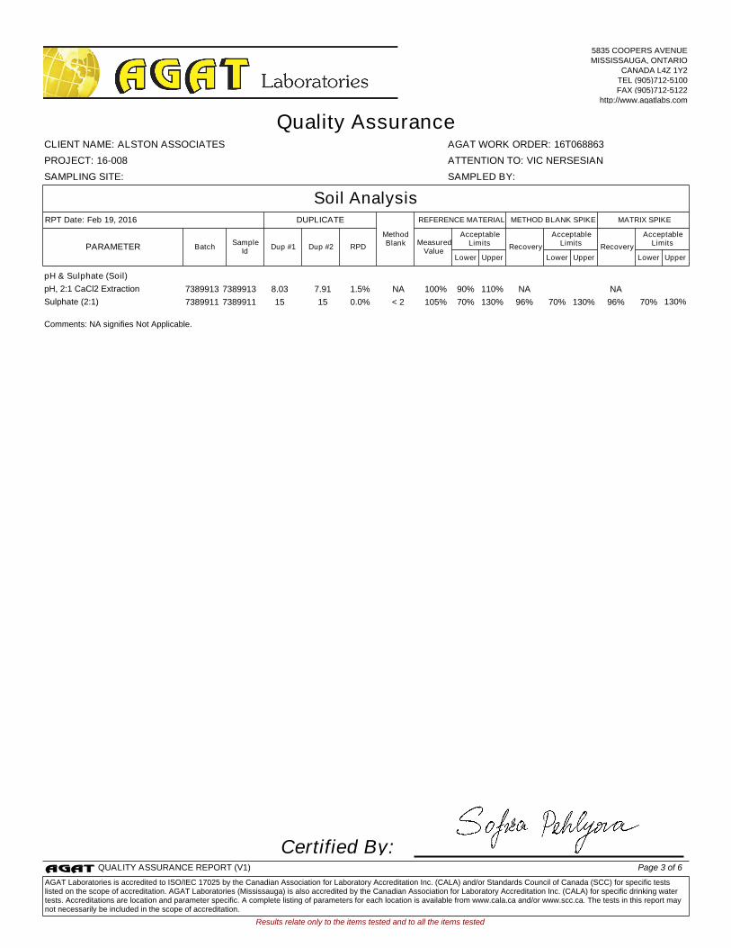
pH, 2:1 CaCl2 Extraction 7389913 7389913 8.03 7.91 1.5% NA 100% 90% 110% NA NA
Sulphate (2:1) 7389911 7389911 15 15 0.0% < 2 105% 70% 130% 96% 70% 130% 96% 70% 130%
Comments: NA signifies Not Applicable.
Certified By:
Results relate only to the items tested and to all the items tested
SAMPLING SITE: SAMPLED BY:
AGAT WORK ORDER: 16T068863
Dup #1 RPDMeasured
ValueRecovery Recovery
Quality Assurance
ATTENTION TO: VIC NERSESIAN
CLIENT NAME: ALSTON ASSOCIATES
PROJECT: 16-008
Soil Analysis
UpperLower
AcceptableLimits
BatchPARAMETERSample
IdDup #2
UpperLower
AcceptableLimits
UpperLower
AcceptableLimits
MATRIX SPIKEMETHOD BLANK SPIKEDUPLICATERPT Date: Feb 19, 2016 REFERENCE MATERIAL
MethodBlank
5835 COOPERS AVENUEMISSISSAUGA, ONTARIO
CANADA L4Z 1Y2TEL (905)712-5100FAX (905)712-5122
http://www.agatlabs.com
QUALITY ASSURANCE REPORT (V1) Page 3 of 6
AGAT Laboratories is accredited to ISO/IEC 17025 by the Canadian Association for Laboratory Accreditation Inc. (CALA) and/or Standards Council of Canada (SCC) for specific tests listed on the scope of accreditation. AGAT Laboratories (Mississauga) is also accredited by the Canadian Association for Laboratory Accreditation Inc. (CALA) for specific drinking water tests. Accreditations are location and parameter specific. A complete listing of parameters for each location is available from www.cala.ca and/or www.scc.ca. The tests in this report may not necessarily be included in the scope of accreditation.
BH3/S3 11-FEB-2016 16-FEB-2016Soil7389911
pH & Sulphate (Soil)pH & Sulphate (Soil)
Date AnalyzedParameter InitialsDate Prepared
19-FEB-2016 AKpH, 2:1 CaCl2 Extraction 19-FEB-2016
19-FEB-2016 MMSulphate (2:1) 19-FEB-2016
BH3/S6 11-FEB-2016 16-FEB-2016Soil7389912
pH & Sulphate (Soil)pH & Sulphate (Soil)
Date AnalyzedParameter InitialsDate Prepared
19-FEB-2016 AKpH, 2:1 CaCl2 Extraction 19-FEB-2016
19-FEB-2016 MMSulphate (2:1) 19-FEB-2016
BH3/S8 11-FEB-2016 16-FEB-2016Soil7389913
pH & Sulphate (Soil)pH & Sulphate (Soil)
Date AnalyzedParameter InitialsDate Prepared
19-FEB-2016 AKpH, 2:1 CaCl2 Extraction 19-FEB-2016
19-FEB-2016 MMSulphate (2:1) 19-FEB-2016
Results relate only to the items tested and to all the items tested
Time Markers
ATTENTION TO: VIC NERSESIANCLIENT NAME: ALSTON ASSOCIATES
AGAT WORK ORDER: 16T068863
PROJECT: 16-008
Sample ID Sample Description Sample Type Date Sampled Date Received
5835 COOPERS AVENUEMISSISSAUGA, ONTARIO
CANADA L4Z 1Y2TEL (905)712-5100FAX (905)712-5122
http://www.agatlabs.com
TIME MARKERS (V1) Page 4 of 6

Soil Analysis
pH, 2:1 CaCl2 Extraction INOR-93-6031 MSA part 3 & SM 4500-H+ B pH METER
Sulphate (2:1) INOR-93-6004 McKeague 4.12 & SM 4110 B ION CHROMATOGRAPH
Results relate only to the items tested and to all the items tested
SAMPLING SITE: SAMPLED BY:
AGAT WORK ORDER: 16T068863
Method Summary
ATTENTION TO: VIC NERSESIAN
CLIENT NAME: ALSTON ASSOCIATES
PROJECT: 16-008
AGAT S.O.P ANALYTICAL TECHNIQUELITERATURE REFERENCEPARAMETER
5835 COOPERS AVENUEMISSISSAUGA, ONTARIO
CANADA L4Z 1Y2TEL (905)712-5100FAX (905)712-5122
http://www.agatlabs.com
METHOD SUMMARY (V1) Page 5 of 6

Page 6 of 6

alston associates inc. Reference 16-008
February 22, 2016
GEOTECHNICAL INVESTIGATION REPORT PROPOSED RESIDENTIAL DEVELOPMENT 1496 BAYLY STREET, PICKERING, ON
APPENDIX F RECOMMENDED PERIMETER DRAINAGE SYSTEM

Notes 1. Drainage tile to consist of 100 mm (4”) diameter weeping tile or equivalent perforated pipe leading to a
positive sump or outlet. 2. 20 mm (3/4”) Clear Stone – 150mm (6”) top and side of drain, 100 mm (4”) of stone below drain. 3. Wrap the clear stone with an approved filter membrane (Terrafix 270R or equivalent). 4. Moisture barrier to be at least 200 mm (8”) of compacted clear 20 mm (3/4”) stone or equivalent free
draining material. A vapour barrier may be required for special floors. 5. Do not connect the underfloor drains to the perimeter drains.
6. Solid discharge pipe outletting into a solid pipe leading to a sump. 7. Vertical drainage board Terradrain 600 or equivalent with filter cloth should be continuous from bottom to
1.2 m below exterior finished grade. 8. Review the geotechnical report for specific details. Final detail must be approved before system is
considered acceptable.
DRAINAGE RECOMMENDATIONS
Shored Basement wall with Underfloor Drainage System (Not to Scale)