Embed Size (px)
Citation preview
PRELIMINARY REVIEW OF APPLICABLE CODES AND STANDARDS,
PROCESS HAZARD ANALYSIS AND OPERATIONAL FIRE SAFETY PLAN
CMC ENGINEERING AND MANAGEMENT LIMITED
2017 June CMC File: 1419-204

Preliminary Review of Applicable Codes and Standards, Process Hazard Analysis and Operational Fire Safety Plan CMC Ref. 1419
S-file: 1419-204 Fire and Life V6.1.docx Page 2 of 59 Printed: 2017 06 20 17:03
TABLE OF CONTENTS
REVISION CONTROL GLOSSARY 0- EXECUTIVE SUMMARY 1- APPLICABLE CODES, STANDARDS, AND LEGISLATION
1.1 NATIONAL BUILDING CODE OF CANADA 1.2 NATIONAL FIRE CODE OF CANADA 1.3 OCCUPATIONAL HEALTH AND SAFETY REGULATION 1.4 SUMMARY OF REFERENCED DOCUMENTS
2- PROCESS HAZARD ANALYSIS
2.1 OBJECTIVES 2.2 IDENTIFIED HAZARDS AT THE FRASER GRAIN TERMINAL FACILITY
3- DESIGN REQUIREMENTS 3.1 INTRODUCTION 3.2 UNLOADING BUILDING
3.2.1 General Construction Requirements 3.2.2 Means of Egress 3.2.3 Building Fire Suppression 3.2.4 Process Hazard Analysis 3.2.5 Code/Standards References 3.2.6 Discussion on Implementation of Safety Measures
3.3 ENCLOSED CONVEYORS 3.3.1 Process Hazard Analysis 3.3.2 Code/Standards References 3.3.3 Discussion on Implementation of Safety Measures
3.4 BUCKET ELEVATORS AND SUPPORT STRUCTURE 3.4.1 Process Hazard Analysis 3.4.2 Code/Standards References 3.4.3 Discussion for Implementation of Safety Measures
3.5 STORAGE SILOS, BATCH SCALE AND SHIPPING BIN 3.5.1 Process Hazard Analysis 3.5.2 Code/Standards References 3.5.3 Discussion for Implementation of Safety Measures
3.6 WHARF/LOADING DOCK 3.6.1 Process Hazard Analysis 3.6.2 Code/Standards References
Preliminary Review of Applicable Codes and Standards, Process Hazard Analysis and Operational Fire Safety Plan CMC Ref. 1419
S-file: 1419-204 Fire and Life V6.1.docx Page 3 of 59 Printed: 2017 06 20 17:03
3.6.3 Discussion for Implementation of Safety Measures 3.7 FIRE DEPARTMENT ACCESS TO FACILITY 3.8 FIREFIGHTING WATER SUPPLY 3.9 FIRE ALARM SYSTEM FOR THE FACILITY
4- OPERATIONAL PLANS 4.1 FIRE SAFETY PLAN AND FIREFIGHTING OPERATIONS 4.2 DUST CONTROL STRATEGY 4.3 TRAINING 4.4 HOT WORK 4.5 SPECIFIC PROCEDURES FOR THE OPERATING PLANT
5- SUMMARY OF RECOMMENDATIONS 5.1 GENERAL 5.2 UNLOADING BUILDING AND PIT AREA
5.2.1 Building Structure 5.2.2 Underground Unloading Pit Area 5.2.3 Underground Belt Conveyors
5.3 ENCLOSED CONVEYORS 5.4 BUCKET ELEVATORS AND SUPPORT STRUCTURES
5.4.1 Bucket Elevators 5.4.2 Support Tower, Bulk Weighers, and Bin
5.5 STORAGE SILOS, BATCH SCALES, AND BINS 5.6 WHARF/LOADING DOCK 5.7 FIRE DEPARTMENT ACCESS TO FACILITY 5.8 FIREFIGHTING WATER SUPPLY 5.9 FIRE DEPARTMENT ACCESS TO FACILITY
ANNEXES
Annex A Fire Protection and Life Safety Drawings Annex B Factory Mutual Data Sheets
Annex C Firefighting System Access Roads Annex D Water Supply and Fire Hydrants
Preliminary Review of Applicable Codes and Standards, Process Hazard Analysis and Operational Fire Safety Plan CMC Ref. 1419
S-file: 1419-204 Fire and Life V6.1.docx Page 4 of 59 Printed: 2017 06 20 17:03
REVISION CONTROL
NUMBER DATE CHANGES REMARKS18 V 6.1 2017 06 20 Reissued for PER. mvn19
REVISION
Preliminary Review of Applicable Codes and Standards, Process Hazard Analysis and Operational Fire Safety Plan CMC Ref. 1419
S-file: 1419-204 Fire and Life V6.1.docx Page 5 of 59 Printed: 2017 06 20 17:03
GLOSSARY The following abbreviations, acronyms and consecrated terms are used in this document:
ITEM MEANING ASTM American Society for Testing and Materials CEC Canadian Electrical Code CMC CMC Engineering and Management Ltd. CSA Canadian Standards Association FM Factory Mutual ISA International Society of Automation NBC National Building Code of Canada
NEMA National Electrical Manufacturers Association NFC National Fire Code of Canada
NFPA National Fire Protection Association MIE Minimum Ignition Energy OHS Occupational Health and Safety P&H Parrish & Heimbecker, Limited PMV Port Metro Vancouver tonne 1 000 kg ULC Underwriters’ Laboratory of Canada
_____________________________
Preliminary Review of Applicable Codes and Standards, Process Hazard Analysis and Operational Fire Safety Plan CMC Ref. 1419
S-file: 1419-204 Fire and Life V6.1.docx Page 6 of 59 Printed: 2017 06 20 17:03
0- EXECUTIVE SUMMARY
The grain handling industry has been part of human civilisation for thousands of years and the potential dangers of handling grain in large quantities has been recognized for nearly as long. These dangers came in the form of potential fires and explosions, and in the past century in particular, the industry has made great progress: In the understanding of the mechanism behind these deflagrations. In deriving solutions to minimize the risks. In the case where incident did occur, in minimizing its detrimental effects. In concert with this technical progress, the world’s regulatory bodies have stepped in and mandated that the design, construction and operation of grain handling facilities be done in accordance with these innovations. The result of this work has seen marked decreases in the frequency of explosions and fires in grain handling facilities.1 This study examines the requirements for fire and life safety at the Fraser Grain Terminal and proposes a series of design features to be implemented. Section 1 of the study (“Applicable Codes, Standards and Legislation”) looks at the aforementioned codes and regulations applicable to the facility. The review starts with the National Building Code of Canada (NBC), in particular, Part 3 which mandates that designers must limit the probability of: A fire or explosion occurring. Fire spread beyond the area of origin. Injury or death. Building damage. From that point the NBC makes reference, either directly or indirectly, to multiple existing codes and guidelines such as: CEC FM NFC NFPA OHS. Each of these documents addresses a specific area of the fire and explosion prevention and damage mitigation scheme and each one presents specific methodologies to achieve the desired objectives.
1 Frequency of Dust Explosions in Grain Storage”; DEMONTIS; Giorgio; CREMANTE; Mio; Tecnica
Molitoria International, vol 63 – n.13/A, 2012, page 70.
Preliminary Review of Applicable Codes and Standards, Process Hazard Analysis and Operational Fire Safety Plan CMC Ref. 1419
S-file: 1419-204 Fire and Life V6.1.docx Page 7 of 59 Printed: 2017 06 20 17:03
Section 2 of the study (“Process Hazard Analysis”) addresses: .1 The major design objectives as defined by NFP 654:
i. Life Safety ii. Structural Integrity iii. Mission Continuity iv. Mitigation of Fire Spread and Explosions.
.2 The specific potential “danger points” at FGT that need to be addressed. Section 3 of the study (“Design Requirements”) then walks through the facility from receiving through to shipping with an analysis for each section of its particular hazards and required solutions. Section 4 is titled “Operational Plans”, and as the name implies, it deals not with design matters but rather the operational procedures to be adopted by the terminal’s operating team. Section 5 presents a “Summary of Recommendations” followed by the annexes which present related drawings and some pertinent data sheets extracted from Factory Mutual. This report and its contents have been reviewed by the client and its risk underwriter.
Preliminary Review of Applicable Codes and Standards, Process Hazard Analysis and Operational Fire Safety Plan CMC Ref. 1419
S-file: 1419-204 Fire and Life V6.1.docx Page 8 of 59 Printed: 2017 06 20 17:03
1- APPLICABLE CODES, STANDARDS, AND LEGISLATION 1.1 NATIONAL BUILDING CODE OF CANADA
The applicable building code for the Fraser Grain Terminal Facility constructed within the Port Metro Vancouver (PMV) functional area is the National Building Code of Canada, 2015 Edition (NBC). The provisions contained in the NBC have been developed and structured to regulate building construction for a general range of typical buildings. Part 3 of the NBC applies to Fire Protection, Occupant Safety and Accessibility of buildings. The primary objectives of Part 3 are to limit the probability of: A fire or explosion occurring; Fire spread beyond the area of origin; Injury or death; and Building damage. The prescriptive fire and life safety requirements of the building code do not always ‘fit’ well when applying the requirements to process buildings. This is recognized in an appendix note to the application of Part 3 of the NBC which states:
In applying the requirements of this Part, it is intended that they be applied with discretion to buildings of unusual configuration that do not clearly conform to the specific requirements, or to buildings in which processes are carried out which make compliance with particular requirements in this Part impracticable. The definition of “building” as it applies to this Code is general and encompasses most structures, including those which would not normally be considered as buildings in the layman’s sense. This occurs more often in industrial uses, particularly those involving manufacturing facilities and equipment that require specialized design that may make it impracticable to follow the specific requirements of this Part. Steel mills, aluminum plants, refining, power generation and liquid storage facilities are examples. A water tank or an oil refinery, for example, has no floor area, so it is obvious that requirements for exists from floor areas would not apply. Requirements for structural fire protection in large steel mills and pulp and paper mills, particularly in certain portions, may not be practicable to achieve in terms of the construction normally used and the operations for which the space is to be used. In other portions of the same building, however, it may be quite reasonable to require that the provisions of this Part be applied (e.g., the office portions). Similarly, areas of industrial occupancy which may be occupied only periodically by service staff, such as equipment penthouses, normally would not need to have the same type of exist facility as floor areas occupied on a continuing basis. It is expected that judgment will be exercised in evaluating the application of a requirement in those
Preliminary Review of Applicable Codes and Standards, Process Hazard Analysis and Operational Fire Safety Plan CMC Ref. 1419
S-file: 1419-204 Fire and Life V6.1.docx Page 9 of 59 Printed: 2017 06 20 17:03
cases when extenuating circumstances require special consideration, provided the occupants’ safety is not endangered.
The NBC provides an alternate means of compliance by recommending that buildings that may be considered as special or unusual structures be protected against fire spread and collapse in conformance with good engineering practice. Recommended publications to establish good engineering practice include the NFPA Fire Protection Handbook, Factory Mutual Data Sheets, and publications of the Society for Fire Protection Engineers.2 In terms of the new facility at the Fraser Grain Terminal, some of the prescriptive requirements of Part 3 of the NBC may be applied to the unloading building; whereas, recommendations of good engineering practice with respect to protection of the conveyors, silos and loading dock will be obtained from the following publications: Factory Mutual Data Sheet FM 7-11: Belt Conveyors, (see Annex B)
Factory Mutual Data Sheet FM 7-75: Grain Storage and Milling, (see Annex B)
NPFA 61, Standard for the Prevention of Fires and Dust Explosions in Agricultural and Food Processing Facilities,
NPFA 68, Explosion Protection by Deflagration Venting,
NFPA 69, Explosion Prevention Systems,
NFPA 654, Prevention of Fire and Dust Explosion from the Manufacturing, Processing Handling of Combustible Particulate Solids,
NPFA 307, Construction and Fire Protection of Marine Terminals, Piers, and Wharves.
1.2 NATIONAL FIRE CODE OF CANADA
The applicable fire code for buildings constructed within the Port Metro Vancouver functional area is the National Fire Code of Canada, 2015 Edition (NFC). The NFC governs the operation and maintenance of the fire-related features of buildings and facilities in use and contains provisions regarding fire safety and fire protection features to be incorporated when certain hazardous activities or processes are present.
2 Sereca Fire Consulting Ltd., Report on Fire and Life Safety Design Review for Wood Pellets Storage and Shipping Facility.
Preliminary Review of Applicable Codes and Standards, Process Hazard Analysis and Operational Fire Safety Plan CMC Ref. 1419
S-file: 1419-204 Fire and Life V6.1.docx Page 10 of 59 Printed: 2017 06 20 17:03
Section 5.3 of the NFC contains provisions where combustible dusts are produced in quantities or concentrations that create an explosion or fire hazard. Such provisions include: dust removal, explosion venting, control of ignitions sources and electrical interlocks. Section 2.8 of the Project Description and Description of Operations document describes design measures intended to minimize product breakage thereby reducing the quantity of dust produced thus decreasing the potential for dust becoming airborne creating an explosive atmosphere. This report will consider the provisions of Section 5.3 of the NFC with respect to their applicability to the Fraser Grain Terminal Facility.
1.3 OCCUPATIONAL HEALTH AND SAFETY REGULATION
The requirements of the Occupational Health and Safety (OHS) Regulation are adopted under the authority of the Workers Compensation Act of April 15, 1998, as amended by the Workers Compensation (Occupational Health and Safety) Amendment Act, effective October 1, 1999. The OHS Regulation contains the requirement to control dust. Some requirements relate to limiting a worker’s exposure to dust to prevent respiratory illnesses; whereas, other requirements are intended to prevent an accumulation of dust that could cause a fire or explosion. WorkSafe BC provided guidelines to the OHS Regulation that are intended to assist with providing ways of complying with the legislation.
1.4 CANADIAN ELECTRICAL CODE
This report will only consider electrical code requirements as referenced in the NBC and NFC that apply to potential ignition sources in explosive atmospheres. Also refer to Section 1.12.4 of the Project Description and Description of Operations document.
1.5 SUMMARY OF REFERENCED DOCUMENTS
Table 1-1 below lists the codes and standards referenced within this report and identified those locations within the facility where codes and standards, other than the NBC and NFC, have been considered in order to establish good engineering practice for the mitigation of risk and protection of equipment.

Preliminary Review of Applicable Codes and Standards, Process Hazard Analysis and Operational Fire Safety Plan CMC Ref. 1419
S-file: 1419-204 Fire and Life V6.1.docx Page 11 of 59 Printed: 2017 06 20 17:03
Table 1-1 Referenced Codes/Standards
Code/Standard Scope Location Applicable
National Building Code 2015 Edition (NBC)
Construction or alteration or a building
Unloading building
National Fire Code 2015 Edition (NFC)
Operation and maintenance of the fire-related features of a building
Entire facility
Canadian Electric Code CSA Standard CSA-C22.1, 2015 Edition (CEC)
Installation and maintenance of electrical equipment
Entire facility
NFPA 13 Standard for the Installation of Sprinkler Systems, 2016 Edition
Standard for sprinkler system design
Sprinklered areas
NFPA 14 Standard for the Installation of Standpipe and Hose Systems, 2016 Edition
Standard for standpipe system design
Standpipes
NFPA 51B Standard for Fire Prevention During Welding, Cutting, and Other Hot Work, 2014 Edition
Standard for provisions to prevent loss of life and property from fire or explosion as a result of hot work
Reference for hot work practices
NFPA 61 Standard for the Prevention of Fires and Dust Explosions in Agricultural and Food Processing Facilities, 2017 Edition
Standard applies to facilities relative to agricultural bulk materials, their by-products, or dusts. This standard has been referred to as equipment and processes are identical to that encountered at facilities with similar combustible dust hazard.
Reference for belt and bucket conveyors.
NFPA 68 Standard on Explosion Protection by Deflagration Venting, 2013 Edition
Standard applies to the design, location, installation, maintenance, and use of devices and systems that vent the combustion gases and pressures resulting from a deflagration
Where the need for deflagration venting has been established
Preliminary Review of Applicable Codes and Standards, Process Hazard Analysis and Operational Fire Safety Plan CMC Ref. 1419
S-file: 1419-204 Fire and Life V6.1.docx Page 12 of 59 Printed: 2017 06 20 17:03
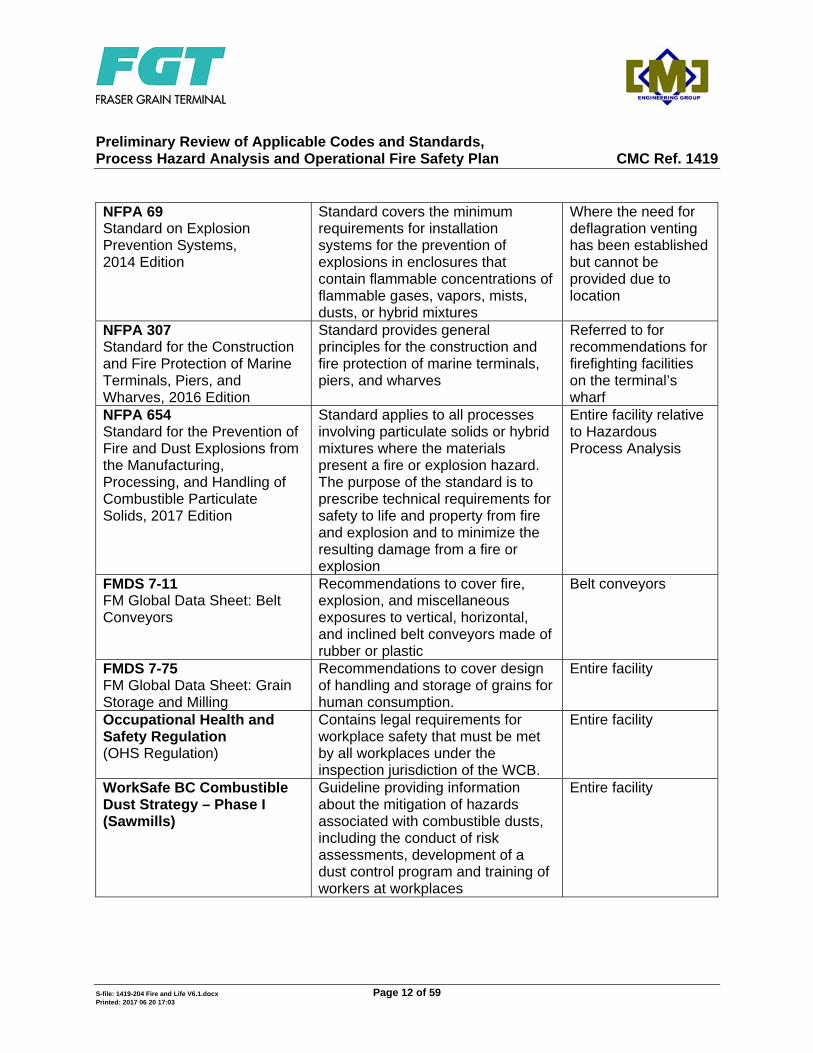
NFPA 69 Standard on Explosion Prevention Systems, 2014 Edition
Standard covers the minimum requirements for installation systems for the prevention of explosions in enclosures that contain flammable concentrations of flammable gases, vapors, mists, dusts, or hybrid mixtures
Where the need for deflagration venting has been established but cannot be provided due to location
NFPA 307 Standard for the Construction and Fire Protection of Marine Terminals, Piers, and Wharves, 2016 Edition
Standard provides general principles for the construction and fire protection of marine terminals, piers, and wharves
Referred to for recommendations for firefighting facilities on the terminal’s wharf
NFPA 654 Standard for the Prevention of Fire and Dust Explosions from the Manufacturing, Processing, and Handling of Combustible Particulate Solids, 2017 Edition
Standard applies to all processes involving particulate solids or hybrid mixtures where the materials present a fire or explosion hazard. The purpose of the standard is to prescribe technical requirements for safety to life and property from fire and explosion and to minimize the resulting damage from a fire or explosion
Entire facility relative to Hazardous Process Analysis
FMDS 7-11 FM Global Data Sheet: Belt Conveyors
Recommendations to cover fire, explosion, and miscellaneous exposures to vertical, horizontal, and inclined belt conveyors made of rubber or plastic
Belt conveyors
FMDS 7-75 FM Global Data Sheet: Grain Storage and Milling
Recommendations to cover design of handling and storage of grains for human consumption.
Entire facility
Occupational Health and Safety Regulation (OHS Regulation)
Contains legal requirements for workplace safety that must be met by all workplaces under the inspection jurisdiction of the WCB.
Entire facility
WorkSafe BC Combustible Dust Strategy – Phase I (Sawmills)
Guideline providing information about the mitigation of hazards associated with combustible dusts, including the conduct of risk assessments, development of a dust control program and training of workers at workplaces
Entire facility
Preliminary Review of Applicable Codes and Standards, Process Hazard Analysis and Operational Fire Safety Plan CMC Ref. 1419
S-file: 1419-204 Fire and Life V6.1.docx Page 13 of 59 Printed: 2017 06 20 17:03
2- PROCESS HAZARD ANALYSIS
NFPA 654, Standard for the Prevention of Fire and Dust Explosions from the Manufacturing, processing, and Handling of Combustible Particulate Solids, is a US standard, adopted in Canada, that provides safety measures to prevent and mitigate fires and dust explosions in facilities that handle combustible particulate solids. It applies to all phases of product processing, blending, pneumatic conveying, and handling of combustible particulate solids or hybrid mixtures, regardless of concentration or particle size, where the materials present a fire or explosion hazard. The purpose of the standard is to prescribe technical requirements for safety to life and property from fire and explosion and to minimize the resulting damage from a fire or explosion. NFPA 654 defines a combustible dust as a combustible particulate solid that presents a fire or deflagration hazard when suspended in air or some other oxidizing medium over a range of concentrations, regardless of particle size or shape. Section 4.2.1 of NFPA 654 requires that the design of the fire and explosion safety provisions be subjected to a Process Hazard Analysis of the facility, the process, and the associated fire or explosion hazards.
Preliminary Review of Applicable Codes and Standards, Process Hazard Analysis and Operational Fire Safety Plan CMC Ref. 1419
S-file: 1419-204 Fire and Life V6.1.docx Page 14 of 59 Printed: 2017 06 20 17:03
2.1 OBJECTIVES
Table 2-1 below lists NFPA 654 objectives relative to the design of the fire and explosion safety provisions:
Table 2-1 Objectives of NFPA 654
Objective Description a. Life Safety The facility, combustible particulate processes, and
human elements programs shall be designed, constructed, equipped, and maintained to protect occupants not in the immediate proximity of the ignition from the effects of fire, deflagration, and explosion for the time needed to evacuate, relocate, or take refuge The structure shall be located, designed, constructed, and maintained to minimize the propagation of fire or explosion to adjacent properties and to avoid injury to the public
b. Structural Integrity The facility shall be designed, constructed, and equipped to maintain its structural integrity in spite of the effects of fire or explosion for the time necessary to evacuate, relocate, or defend in place occupants not in the immediate proximity of the ignition
c. Mission Continuity The facility, processes and equipment, and human element program shall be designed, constructed, equipped, and maintained to limit damage to levels that ensure the ongoing mission, production, or operating capability of the facility to a degree acceptable to the owner/operator
d. Mitigation of Fire Spread and Explosions
The facility and processes shall be designed to prevent fires and explosions that can cause failure of adjacent compartments, emergency life safety systems, adjacent properties, adjacent storage, or the facility’s structural elements The structure shall be designed, constructed, and maintained to prevent fire or explosions from causing failure of load-bearing structural members, propagating into adjacent interior compartments, and incapacitating fire protective and emergency life safety systems in adjacent compartments The structure shall be located, designed, constructed, equipped, and maintained to prevent the propagation of fire or explosion to or from adjacent storage or structures
Preliminary Review of Applicable Codes and Standards, Process Hazard Analysis and Operational Fire Safety Plan CMC Ref. 1419
S-file: 1419-204 Fire and Life V6.1.docx Page 15 of 59 Printed: 2017 06 20 17:03
2.2 IDENTIFIED HAZARDS AT THE FRASER GRAIN TERMINAL FACILITY
The handling and storage of grain presents two main hazards: a readily combustible fuel load with potential ignition sources present and a dust explosion hazard. Based upon the configuration of the facility and the properties of the types of grain handled, the following scenarios have been identified: Large combustible fuel load with potential ignition sources (1) Process Equipment Failure/Heating: Heat produced from an overheated
bearing, misaligned belt, or motor failure has the potential to ignite the conveyor belt and subsequently ignite the grain.
(2) Introduction of Smouldering Material: A fugitive ember and/or smouldering material, from an off-site loading facility could ignite the grain within the railcar.
Dust explosion (3) Unloading Area: The initial release of grain from a railcar could cause dust to
become airborne in the area of the unloading process. After the initial discharge, once the flow of grain into the hopper is established the amount of fugitive dust is expected to reduce relative to the initial release. Some dust is normally expected to be present in railcar from off-site loading operation.
(4) Enclosed Conveyors and Transfer Points: Dust within enclosed belt conveyors could provide a combustible mixture if sufficient dust is entrained in the air. Grain travelling or equipment vibration can cause dust to become airborne. Conveyor speed and the friction forces exerted on the grain at transfer points could be the most important factors relative to the amount of dust created and entrained through the conveyor system.
(5) Bucket Elevator: The potential for dust from the conveyed product to become suspended in the air is high within the bucket elevator; specifically on the downward leg, where residual dust from the buckets can filter through the downside of the casing3.
(6) Silos: The installation of ‘flow retarders’ in the silos is expected to assist with the integrity of grain and reduce the entrainment of dust during the filling of the silos; however, a small amount of dust could still be expected to be released by this process.
3 FM Global Property Loss Prevention Data Sheet 7-75: Belt Conveyors.
Preliminary Review of Applicable Codes and Standards, Process Hazard Analysis and Operational Fire Safety Plan CMC Ref. 1419
S-file: 1419-204 Fire and Life V6.1.docx Page 16 of 59 Printed: 2017 06 20 17:03
(7) Dust from Maintenance Cleaning Processes: Use of compressed gas or other methods of cleaning may result in the lifting of dust into the air, resulting in a dust cloud. If the concentration of dust is within the explosible limit parameters and subsequently comes into contact with a potential source of ignition a dust explosion could occur.
There are four major factors that influence risk and subsequent severity of a dust explosion: the fuel (dust) concentration,
oxygen availability,
the presence of an ignition source, and
confinement (such as enclosed conveyor or bucket elevator casing)4. In many industrial processes oxygen availability is typically not practical to control and confined areas, such as silos and enclosed conveyors, provide the potential for large overpressures in the event of an explosion. Accordingly, practical measures at mitigating the risk of dust explosions in confined spaces involve controlling the dust concentration and any potential ignition sources. Within the process equipment potential ignition sources include hot surfaces (which can arise from overheated bearings, misaligned belts, or other components failures), energy from electrical devices, smouldering process material, and electrostatic discharge. The accumulation of dust on the surfaces of equipment and in areas proximal to process equipment adds to propensity for secondary dust explosions. The pressure front of the primary dust explosion can cause entrainment and ignition of proximal dust deposits, yielding secondary dust explosions which can be larger and more damaging than the initial explosion. Secondary dust explosions result in a significant increase in the degree and extent of damage, and can be most effectively controlled with good housekeeping measures relative to dust accumulation. In addition to the scenarios identified above, the design standards that will be adopted for the design of the fire and explosion safety provisions will also consider the difficulty in physically accessing some areas of the facility to manually fight a fire such as the subgrade conveyors, the conveyors located at the top of silos, and conveyors located at elevations greater than 12 m, as well as the upper portion of bucket elevators and support tower.
4 C. Jones, Preventing Grain Dust Explosions, Oklahoma Cooperative Extension Service, BAE-1737,
Oklahoma State University, July 2011.
Preliminary Review of Applicable Codes and Standards, Process Hazard Analysis and Operational Fire Safety Plan CMC Ref. 1419
S-file: 1419-204 Fire and Life V6.1.docx Page 17 of 59 Printed: 2017 06 20 17:03
3- DESIGN REQUIREMENTS 3.1 INTRODUCTION
In this section of the report the Fraser Grain Terminal Facility has been divided into a number of areas with respect to outlining the applicable fire and explosion safety provisions and discussion relative to good engineering practices. Those areas are: The unloading building, including the underground unloading pit and the bucket
elevator pit, The rail and truck loading building, The container loading structure, Enclosed belt conveyors, including:
o Belt conveyors located below grade, o Belt conveyors located above the silos, and o Belt conveyors located at ground level below the silos, and o Shipping conveyor from bulk weigher to shilploader,
Bucket elevators and support structures, Storage silos, bulk weigher, and shipping bin, Wharf/vessel loading dock.
3.2 UNLOADING BUILDING 3.2.1 General Construction Requirements
As discussed in Section 1.5, the prescriptive requirements of Part 3 of the NBC may be applied to the unloading building. However, the unloading building is a one storey building and approximately 300 m2 in building area. One storey building even if classified as F1 occupancy does not require installation of automatic sprinkler system. Furthermore the building is open to the atmosphere by two large openings (the railcar entrance and exit doors). There is very small potential for combustible dust to be present in the atmosphere following discharge from the railcars through a bar grate to the loading hopper feeding the first conveyor. The unloading pit itself, although the ceiling is covered by the hopper feeding the conveyor, is not considered a basement storey or crawl space but part of the first storey, similar to a pit in a repair garage. The pit is accessed from within the building at the railcar level by open stairs located at either end of the unloading pit.
Preliminary Review of Applicable Codes and Standards, Process Hazard Analysis and Operational Fire Safety Plan CMC Ref. 1419
S-file: 1419-204 Fire and Life V6.1.docx Page 18 of 59 Printed: 2017 06 20 17:03
3.2.2 Means of Egress
The operational staff requirement is that only 1 to 2 personnel will be in the building during normal operating hours. As indicated above, the walls of the unloading building are open on the north and south side providing direct access to the exterior. Sentence 3.3.1.3.(7) of the NBC requires two points of egress for a service space if the travel distance measured from any point in the service space to a point of egress is more than 25 m. Means of egress in compliance with the NBC requirements have therefore been located at each end of the underground unloading pit. The unloading pit housing conveyor is approximately 45 m in length. Exit signage is not required in this building (NBC Article 3.4.5.1.); however, exits, including the below grade conveyors areas will be provided with emergency lighting.
3.2.3 Building Fire Suppression 3.2.3.1 Standpipe System
As a one storey, 300 m2 building, high hazard industrial occupancy and falling outside the F1, the NBC does require this structure to be provided with a sprinkler system. However, it is recommended that at least one fire hose station complete with fog and fine spray nozzles be provided in the vicinity of the unloading building. Fine and fog spray nozzles are specified to prevent combustible dust from being raised into suspension upon application of a solid stream of water discharge (NFC Article 5.3.3.4.). The fire hose station will be located to provide coverage of all parts of the first storey and underground pit.
3.2.3.2 Automatic Sprinkler System The requirement for sprinklers in the unloading building would be triggered only by an F1 occupancy classification. The unloading building is not classified as such. For informational purposes, an automatic sprinkler system in the unloading building would provide protection relative to a fire within a railcar prior to or during the unloading process. As a railcar would only be expected in the unloading building while employees are present to supervise the unloading operation, operational procedures would be implemented to detect potential ignition sources such as a smouldering product being discharged from the railcar or detect overheated railcar brakes. These potential ignition
Preliminary Review of Applicable Codes and Standards, Process Hazard Analysis and Operational Fire Safety Plan CMC Ref. 1419
S-file: 1419-204 Fire and Life V6.1.docx Page 19 of 59 Printed: 2017 06 20 17:03
sources could be dealt with (either inside or outside the building) using the facility’s standpipe system prior to unloading the grain. Proper training of facility personnel in the use of a standpipe system will be implemented to provide an equal level of protection when compared with automatic sprinklers.
3.2.3.3 Fire Alarm Article 3.2.4.1 of the NBC requires that a fire alarm system shall be installed in buildings which require the installation of an automatic sprinkler system. The unloading building does not require a sprinkler system, therefore does not require a fire alarm system.
3.2.3.4 Fire Extinguishers Fire extinguishers are required to be installed in accordance with NFPA 10 (BCFC 2.1.5). NFPA 10 requires: The maximum travel distance to an extinguisher is 22.9 m (NFPA 10 –
Table 6.2.1.1),
The minimum fire extinguisher rating for extra hazard is 4-A (NFPA 10 – Table 6.2.1.1), and
Up to one-half of the extinguishers specified in Table 6.2.1.1 shall be permitted to be replaced by uniformly spaced 38 mm (1½”) hose stations for use by the occupant of the building (NFPA 10 – 5.2.2).
Where hose stations are so provided, they shall conform to NFPA 14.
3.2.4 Process Hazard Analysis
Relative to the identification of locations where combustible dust has the propensity to create an explosion hazard, NFPA 654, Standard for the Prevention of Fire and Dust Explosion from the Manufacturing, Processing, and Handling of Combustible Particular Solids, considers locations where combustible dust is in the air under normal operating conditions in quantities sufficient to produce explosive or ignitable mixtures; or, where mechanical failure or abnormal operation of machinery or equipment could cause explosive or ignitable mixtures to be produced, and could also provide a source of ignition through simultaneous failure of electrical equipment, operation of protection devices, or from other causes. Applying this rationale to the area of the unloading building, considering the special baffle design installed on the unloading pit and air aspiration in the unloading hopper, there is low potential for combustible dust to be raised following the initial discharge from the railcards through the bar grate to the loading hopper feeding the first conveyor.
Preliminary Review of Applicable Codes and Standards, Process Hazard Analysis and Operational Fire Safety Plan CMC Ref. 1419
S-file: 1419-204 Fire and Life V6.1.docx Page 20 of 59 Printed: 2017 06 20 17:03
Furthermore, the end walls of the unloading building around this discharge location are open to the atmosphere, thus eliminating the possibility of an explosion. Within the underground unloading pit area, the unloading hopper and receiving conveyor will be totally enclosed, thus providing separation between the flow of grain and the air space around the pit enclosure. Accordingly, under normal operating conditions there would be minimal opportunity for dust introduction into the unloading pit air space around the hopper and the conveyor.
3.2.5 Code/Standards References
The relevant code references which will be adopted for the unloading building and pit area are outlined below.
NBC 3.2.5.11.(7) – Where a hose station is provided in grain handling and storage facilities in which combustible dusts are produced in quantities or concentrations that create an explosion or fire hazard, fog and fine spray nozzles shall be used instead of nozzles that discharge a solid stream of water to prevent combustible dusts from being raised into suspension. 3.3.1.20.(1) – An exhaust ventilation system designed in conformance with the appropriate requirements of Part 6 shall be provided in a building or part of a building in which dust, fumes, gases, vapour or other impurities or contaminants have the potential to create a fire or explosion hazard. 3.3.1.20.(2) – Explosion relief devices, vents or other protective measures conforming to Subsection 6.2.2. shall be provided for a space in which substances or conditions that have a potential to create an explosion hazard are present as a result of the principal use of a building. 3.3.6.2.(4) – Where wiring or electrical equipment is located in areas in which flammable gases or vapours, combustible dusts or combustible fibres are present in quantities sufficient to create a hazard, such wiring and electrical equipment shall conform to CSA C22.1, “Canadian Electrical Code, Part I,” for hazardous locations. 6.2.2.6.(1) – (Ventilation Systems serving spaces that contain hazardous gases, dusts or liquids shall be designed, constructed and installed to conform to the requirements of the applicable provincial or territorial regulations or municipal bylaws or, in the absence of such regulations or bylaws, to good engineering practice such as that described in the publication of the National Fire Protection Association and in the NFC.
Preliminary Review of Applicable Codes and Standards, Process Hazard Analysis and Operational Fire Safety Plan CMC Ref. 1419
S-file: 1419-204 Fire and Life V6.1.docx Page 21 of 59 Printed: 2017 06 20 17:03
The NBC Appendix note A-6.2.2.5.(1) includes the following relevant NFPA standards as deemed to be good engineering practice: NFPA 68, Standard on Explosion Protection by Deflagration Venting
NFPA 654, Standard for the Prevention of Fire and Dust Explosion from the Manufacturing, Processing, and Handling of Combustible Particular Solids.
In the event of a dust explosion, vents reduce risks to life safety and limit the potential for structural damage to process equipment and buildings by relieving the significant internal pressures from deflagrations. NFC 5.3.1.2. Dust Removal
(1) Building and machinery surfaces shall be kept clean of accumulations of combustible dusts using cleaning equipment that:
a) is made of materials that will not create electrostatic charges or
sparks, b) is electrically conductive and bonded to ground, and c) except as permitted in Sentence (3), removed the dust to a safe
location by vacuum.
(2) Cleaning equipment required in Sentence (1) that is used in an atmosphere containing combustible dusts shall conform to CSA C22.1, “Canadian Electrical Code, Part I”.
(3) Where it is not possible to effectively remove the dust by vacuum, it is
permitted to use compressed air or other means that will cause the dust to become suspended in the air during removal if, in the dust removal area,
a) all sources of ignition are eliminated, and
b) all machinery and equipment is de-energized, unless such machinery
or equipment is suitable for use in atmospheres containing combustible dusts, in conformance with CSA C22.1, “Canadian Electrical Code, Part I”.
Preliminary Review of Applicable Codes and Standards, Process Hazard Analysis and Operational Fire Safety Plan CMC Ref. 1419
S-file: 1419-204 Fire and Life V6.1.docx Page 22 of 59 Printed: 2017 06 20 17:03
5.3.1.3.(1) Dust-collecting systems shall be provided to prevent the accumulation of dust and keep suspended dusts at a safe concentration inside a building.
5.3.1.5. Bonding and Grounding
(1) Electrically conducting parts of conveying systems, dust collectors, dust-producing machines and any equipment capable of accumulating static electricity locating in an atmosphere containing combustible dusts shall be electrically bonded and grounded.
(2) Static electricity shall be prevented from accumulating on machines or
equipment subject to static electricity buildup by appropriate bonding, grounding, and static eliminating devices.
5.3.1.6. Explosion Venting
(1) Except as provided in Article 5.3.1.7., an activity that creates an atmosphere containing significant concentrations of combustible dusts shall be located only in a building provided with explosion venting to the outdoors.
(2) When explosion venting is required in this Section (Dust-Producing
Processes), it shall be designed to prevent critical structural and mechanical damage to the building in conformance with good engineering practice such as that described in NFPA 68, Explosion Protection by Deflagration Venting.
5.3.1.7. Explosion Prevention Systems
(1) In a process where an explosion hazard is present and conditions exist that prevent adequate explosion venting as required in this Section (Dust-Producing Processes), an explosion prevention system shall be provided.
(2) When explosion venting is required in this Section, it shall be designed
to prevent critical structural and mechanical damage to the building in conformance with good engineering practice such as that described in NFPA 68, “Explosion Protection by Deflagration Venting”.
NFPA 654 6.4.1 If a room or building contains a dust explosion hazard as specified in 6.2.3.1
that is external to protected equipment, such areas shall be provided with deflagration venting to a safe outside location.
Preliminary Review of Applicable Codes and Standards, Process Hazard Analysis and Operational Fire Safety Plan CMC Ref. 1419
S-file: 1419-204 Fire and Life V6.1.docx Page 23 of 59 Printed: 2017 06 20 17:03
8.2.1.1 Where the facility is intended to be operated with less than the dust accumulation defined by the owner/operator’s chosen criterion in Section 6.1, the housekeeping frequency shall be established to ensure that the accumulated dust levels on walls, floors, and horizontal surfaces such as equipment, ducts, pipes, hoods, ledges, beams, and above suspended ceilings and other concealed surfaces, such as the interior of electrical enclosures, does not exceed the threshold dust mass/accumulation.
8.2.1.2 Where the facility is intended to be operated with less than the dust
accumulation defined by the owner/operator’s chosen criterion in Section 6.1, a planned inspection process shall be implemented to evaluate dust accumulation rates and the housekeeping frequency required to maintain dust accumulations below the threshold dust mass/accumulation.
8.2.1.3 Where the facility is intended to be operated with less than the dust
accumulation defined by the owner/operator’s chosen criterion in Section 6.1, the housekeeping procedure shall include specific requirements establishing time to clean local spills or short-term accumulation to allow the elimination of the spilled mass or accumulation from the calculations in Section 6.1.
8.2.2.1 Surfaces shall be cleaned in a manner that minimizes the generation of dust
clouds. NFPA 61 6.2.1 If a dust explosion hazard exists in rooms, buildings, or other enclosures
under normal operating conditions, such areas shall be provided with explosion relief venting distributed over the exterior walls (and roof, if applicable) in accordance with NFPA 68, Standard on Explosion Protection by Deflagration Venting.
Exception No. 1: Tunnels and pits where explosion venting is not practical
due to confinement by soil, building constraints, or both. Exception No. 2: Bins and silos where explosion venting is not practical due
to bin or silo geometry, building constraints, or both. 6.2.1.1 The design of such explosion relief venting shall consider the limitations
imposed by the structural design of the area.
Preliminary Review of Applicable Codes and Standards, Process Hazard Analysis and Operational Fire Safety Plan CMC Ref. 1419
S-file: 1419-204 Fire and Life V6.1.docx Page 24 of 59 Printed: 2017 06 20 17:03
6.2.1.2 The design shall offer the least possible resistance to explosion pressures. A.6.2.1 These are locations in which combustible dust is in the air under normal
operating conditions in quantities sufficient to produce explosive or ignitable mixtures; or where mechanical failure or abnormal operation of machinery or equipment could cause explosive or ignitable mixtures to be produced, and could also provide a source of ignition through simultaneous failure of electrical equipment, operation of protection devices, or from other causes.
10.3.1 A method shall be used to prevent the escape of dust from process equipment
into the surrounding environment. Occupational Health and Safety (OHS) Regulation 4.72 Design and operation
(1) An employer must ensure that a ventilation system for the supply and distribution of air and removal of indoor air contaminants is designed, constructed and operated in accordance with:
a) established engineering principles, and b) ASHRAE Standard 62-1989, Ventilation for Acceptable Indoor Air
Quality. (2) An adequate supply of outdoor air must be provided to the workplace in
accordance with Table 2 of ASHRAE Standard 62-1989.
5.81 Combustible dust
If combustible dust collects in a building or structure or on machinery or equipment, it must be safely removed before accumulation of the dust could cause a fire or explosion.
5.71 Flammable air contaminants
(1) If an operation or work process produces a combustible or flammable air contaminant in concentrations that may present a risk of fire or explosion, the employer must provide a separate exhaust ventilation system for the operation or work process.
(2) Electrical components of an exhaust ventilation system required bv
subsection (1) must comply with Class II Division I requirement of CSA
Preliminary Review of Applicable Codes and Standards, Process Hazard Analysis and Operational Fire Safety Plan CMC Ref. 1419
S-file: 1419-204 Fire and Life V6.1.docx Page 25 of 59 Printed: 2017 06 20 17:03
Standard C22.1-94, Canadian Electrical Code, Part 1 if the components contact the air stream.
(3) A dust collector having an internal volume greater than 0.6 m3 (20 ft3) and
being used to control combustible dusts must be located and constructed so that no worker will be endangered in the event of an explosion inside the collector.
3.2.6 Discussion on Implementation of Safety Measures
The unloading building features open exterior end walls. Subsequently, the area in which grain will be unloaded from railcars is not an enclosed space. Dust that is entrained during the initial unloading of grain will be exposed to the atmosphere, reducing the potential for the development of significant overpressures in the event of dust ignition. The potential for explosive dust concentrations within the unloading pit below the unloading area will depend upon the operation and condition of enclosed conveyor and the integrity of the enclosed interface with the loading hopper. The life-safety risk of a dust explosion within the unloading pit depends upon if the area is expected to be occupied by personnel during the operation of the equipment. There are no operating personnel in the pit area and to limit the risk, maintenance personnel may not be allowed while equipment is operating. The NFC states that if explosion venting is not possible within a process then explosion prevention is necessary. The below-grade location of the pit for the receiving conveyor belts limits the opportunity for proper explosion venting throughout this area. Accordingly, control of the dust accumulation and reduction of potential ignition hazards would provide the most effective explosion mitigation. Provision of air aspiration and subjecting the conveyor and unloading hopper enclosures to negative pressure will eliminate dust escaping the enclosures and becoming airborne in the unloading pit area. Furthermore, proper sealing of the enclosures and conveyor transfer points minimizes dust migration to the pit area. Frequent cleaning to prevent dust accumulation on any surfaces within the pit would be carried out to aid in reducing the risk. The NBC requires that an exhaust ventilation system be in the unloading pit area. Subsequently, the following features will be provided: A ventilation system within the unloading pit to control the concentration of airborne
dust in the pit and maintain respiratory conditions specified by the OHS Regulation.
Preliminary Review of Applicable Codes and Standards, Process Hazard Analysis and Operational Fire Safety Plan CMC Ref. 1419
S-file: 1419-204 Fire and Life V6.1.docx Page 26 of 59 Printed: 2017 06 20 17:03
A cleaning program will be implemented to prevent the accumulation of dust buildup on any surfaces with the pit, using a vacuum system listed for use in Class II hazardous locations or other methods of cleaning that do not have the potential to create explosible conditions (such as blowing dust with compressed air).
Common ignition sources for dust explosions include hot surfaces, electrical devices, sparks from cutting/welding, and static electrical discharge. Features introduced relative to reducing the ignition risk are outlined below: Installation of intrinsically safe electrical components within the unloading pit area
with wiring conforming to the Canadian Electrical Code for hazardous locations,
Temperature monitoring of bearings and at any other location within the pit in which elevated temperatures may develop during operation,
Provide proper bonding and grounding of all equipment and use antistatic belt material to avoid static electrical buildup.
3.3 ENCLOSED CONVEYORS
The conveyors within the facility will be totally enclosed. The conveyors are categorized according to their function, as described below: Receiving conveyor: Located below grade, running from the unloading pit to the
bucket elevator.
Transfer conveyors: Located above ground level and on top of silos at a height varying from a few metres to 40 m and from the top of the bucket elevators to the top of the storage silos.
Reclaim conveyors: Located above ground level but below the silos, these run from the storage silos to the shipping bulk weigher, container loading structure and railcar and truck loading building.
Shipping conveyors: Running from shipping bulk weigher at a few metres above ground level to the shiploader at heights varying from ground level up to about 40 m.
3.3.1 Process Hazard Analysis
Relative to agricultural grain processing equipment, there is potential for dust explosions at transfer points within enclosed conveyor and inside bucket elevators where the propensity for dust to become suspended in air is increased with the vertical circulation
Preliminary Review of Applicable Codes and Standards, Process Hazard Analysis and Operational Fire Safety Plan CMC Ref. 1419
S-file: 1419-204 Fire and Life V6.1.docx Page 27 of 59 Printed: 2017 06 20 17:03
of the product and the surrounding air5 6. At transfer points accumulated dust can be dislodged by product flow and changes in direction. These enclosed spaces facilitate rapid increases in dust concentration when compared with well ventilated, open area. Accordingly, small amount of accumulated dust can generate explosive conditions.7 The initial discharge of grain from the railcars into the unloading hopper and from there to the enclosed conveyor, will cause dust to be entrained in the air within the conveyor enclosure. At transfer points, including the transfer of grain to/from the bucket elevator and from the storage silos onto the supply conveyors, the potential for product breakup and entrainment of dust is increased. Within the limited air space of the enclosed conveyors small quantities of dust would have the potential to general explosible conditions that could cause significant damage. Ignition sources within the conveyors include hot surfaces associated with idler bearing, electrical devices, introduction of smouldering material into the process stream, and electrostatic discharge. In addition, the location of the conveyors provides some additional risk. Specifically: Receiving conveyor located within the unloading pit below grade.
Conveyors above the silos and conveyors feeding the shiploader are located at a height up to approximately 40 metres. Consequently, access to these conveyors in the event of a fire would be significantly more difficult, resulting in impeded firefighting capabilities.
3.3.2 Code/Standards References
Some of the relevant requirements of the NFC and OHS Regulation are discussed in Section 3.2.5.
5 C. Jones, Preventing Grain Dust Explosions, Oklahoma Cooperative Extension Service, BAE-1737,
Oklahoma State University, July 2011. 6 D.D. Jones, G90-990 Explosion Venting and Suppression of Bucket Elevator Legs, Historical Materials
from University of Nebraska – Lincoln Extension, Paper 1318, 1190. 7 Investigation Report – Sugar Dust Explosion and Fire, U.S. Chemical Safety and Hazard Investigation
Board, Report No. 2008-05-I-GA, September 2009.
Preliminary Review of Applicable Codes and Standards, Process Hazard Analysis and Operational Fire Safety Plan CMC Ref. 1419
S-file: 1419-204 Fire and Life V6.1.docx Page 28 of 59 Printed: 2017 06 20 17:03
NFC 5.3.3.2. Conveying Equipment
(1) Belt conveyors and bucket elevator legs will be equipped with safety devices to:
a) detect excessive misalignment, blockage, slipping, or slow-down of
the conveying equipment, and, b) prevent conditions described in Clause (a) from creating a fire or
explosion hazard by:
i) alerting personnel trained in taking appropriate actions, or ii) automatically stopping the conveying equipment.
(2) Conveying equipment belt will be made of static conductive materials to
prevent buildup of static charges. (3) Conveying equipment bearings will be:
a) accessible for inspection and maintenance, b) lubricated to prevent overheating, and c) kept free of accumulation of combustible dusts.
(4) Belt conveyor galleries and tunnels, if any, and bucket elevator leg enclosures will be provided with explosion venting to the outdoors in conformances with Sentence 5.3.1.6.(2).
Preliminary Review of Applicable Codes and Standards, Process Hazard Analysis and Operational Fire Safety Plan CMC Ref. 1419
S-file: 1419-204 Fire and Life V6.1.docx Page 29 of 59 Printed: 2017 06 20 17:03
NFPA 654 7.1.4 Explosion Protection for Equipment 7.1.4.1 The design of explosion protection for equipment shall incorporate one or
more of the following methods of protection:
(1) Oxidant concentration reduction in accordance with NPFA 69, Standard on Explosion Prevention Systems: a) Where oxygen monitoring is used, it shall be installed in accordance
with ISA 84.00.01, Functional Safety: Application of Safety Instrumented Systems for the Process Industry Sector
b) Where the chemical properties of the material being conveyed
require a minimum concentration of oxygen to control pyrophoricity, that level of concentration shall be maintained.
(2) Deflagration venting in accordance with NFPA 68, Standard on
Explosion Protection by Deflagration Venting (3) Deflagration pressure containment in accordance with NFPA 69,
Standard on Explosion Prevention Systems (4) Deflagration suppression systems in accordance with NFPA 69,
Standard on Explosion Prevention Systems
(5) Dilution with a non-combustible dust to render the mixture non-combustible (See 7.1.4.2)
(6) Deflagration venting through a listed dust retention and flame-arresting
device
7.11 Enclosed Conveyors 7.11.1.1 Where an explosion hazard exists within enclosed conveyors, they shall be
protected in accordance with 7.1.4. 7.11.1.2 Housings for enclosed conveyors shall be of metal construction and shall be
designed so as to prevent escape of combustible dusts. 7.11.2.1 All conveyors shall be equipped with a device that shuts off the power to the
drive motor and sounds an alarm in the event the conveyor plugs.
Preliminary Review of Applicable Codes and Standards, Process Hazard Analysis and Operational Fire Safety Plan CMC Ref. 1419
S-file: 1419-204 Fire and Life V6.1.docx Page 30 of 59 Printed: 2017 06 20 17:03
9.3 Static Electricity 9.3.2.1 All system components shall be electrically conductive. 9.3.2.2 Nonconductive system components shall be permitted where all of the
following conditions are met:
(1) Hybrid mixtures are not present. (2) Conductive dusts are not handled. (3) The MIE of the material being handled is greater than 3 mJ. (4) The nonconductive components do not result in isolation of conductive
components from ground. (5) The breakdown strength across nonconductive sheets, coatings, or
membranes does not exceed 4 kV when used in high surface charging processes.
9.3.2.3 Bonding and grounding with a resistance of less than 1.0 x 10⁶ ohms to
ground shall be provided for conductive components. 10.1 General
Fire protection systems, where installed, shall be specifically designed to address building protection, process equipment, and the chemical and physical properties of the materials being processed.
NFPA 61 6.3.1 Equipment requiring explosion prevention shall be protected by containment,
suppression, inerting, or explosion venting. 7.1.1 Antifriction bearing shall be used on all machinery, conveyors, legs, and
processing equipment. Exception: Sleeve and friction-type bearings, plastic bearings, or oil-impregnated wood
bearings shall be permitted for equipment operating at 150 rpm or less.
Preliminary Review of Applicable Codes and Standards, Process Hazard Analysis and Operational Fire Safety Plan CMC Ref. 1419
S-file: 1419-204 Fire and Life V6.1.docx Page 31 of 59 Printed: 2017 06 20 17:03
7.1.3 All bearings on legs and conveyors shall be located outside of machinery enclosures and isolated from the product stream to minimize exposure to dust and to be more accessible for inspection and service.
Exception: Antifriction support bearings on screw conveyors and similar equipment
requiring bearings to be within the product stream shall be of the sealed type. Sleeve and friction-type bearings shall be permitted for equipment operating at 150 rpm or less.
7.3.2 Bulk material conveyor belts shall have belt alignment and hot bearing
sensors at the head and tail. 7.5.1.3 Equipment shall be bonded and grounded to dissipate static electricity. NFPA 69 6.1.1 Methods based on Prevention of Combustion
The following shall be considered methods based on preventing combustion:
(1) Oxidant concentration reduction (2) Combustible concentration reduction
6.1.2 Methods based on Prevention of Limitation of Damage
The following shall be considered methods based on preventing or limiting damage:
(1) Predeflagration detection and ignition control systems (2) Deflagration suppression (3) Isolation methods (4) Deflagration pressure containment
FM Global Data Sheet 7-11: Belt Conveyors (Refer to Annex B) 2.3.1.1 Provide automatic sprinkler protection over indoor and outdoor conveyor
belts unless they meet all of the following criteria:
The conveyor belt has a fire propagation index of 7 or lower (ASTM E2058).
Preliminary Review of Applicable Codes and Standards, Process Hazard Analysis and Operational Fire Safety Plan CMC Ref. 1419
S-file: 1419-204 Fire and Life V6.1.docx Page 32 of 59 Printed: 2017 06 20 17:03
The material being conveyed is non-combustible.
The enclosure housing the conveyor belt is of non-combustible construction.
No combustible materials are present near or under the conveyor belt.
2.3.3.5.4 Provide sprinkler protection where dust-tight enclosures are used to prevent or minimize dust liberation from belt conveyors; provide sprinklers inside the enclosures per Figure 2 (FM 7-11 see Annex B). Provide sprinklers at the ceiling of the tunnel, gallery, or building housing the enclosed conveyor only if construction is combustible, or if other combustibles, such as grouped electrical cables, are present.
3.3.3 Discussion on Implementation of Safety Measures
The reduced belt speeds of less than approximately 2.54 m/s proposed for the facility will be expected to reduce product breakup and dust lifted from the product within the moving belt. However, the degree to which generated/lifted dust will be reduced at transfer points within the enclosed conveyors is difficult to quantify without system and material-specific testing. Subsequently, at locations such as the unloading hopper/receiving conveyor interface and transfer points, the entrainment of dust into the air could still present an explosion risk, although small. In accordance with good engineering practices outlined in NFPA 61 and NPFA 654, the following features are recommended: The enclosures of the conveyors will be designed and configured to be dust-tight,
For each conveyor an aspiration fan-filter combination will extract lifted dust at the transfer points to reduce dust in suspension, thus possibilities of explosions.
However at locations such as the receiving conveyor, being below grade, could have the potential to limit the effectiveness of explosion venting for the enclosed conveyors, if the conveyor explosion vents exhaust pressure into an enclosed space. The intended effect of explosion venting for the conveyors would subsequently be compromised by the surrounding pit enclosure, if the developed pressure could not be properly vented to the atmosphere. If explosion venting to the atmosphere from the receiving conveyors is not feasible due to structural design constraints, additional preventative measures are warranted. As discussed previously, the NFC states that if explosion venting is not possible within a process then explosion prevention is necessary.
Preliminary Review of Applicable Codes and Standards, Process Hazard Analysis and Operational Fire Safety Plan CMC Ref. 1419
S-file: 1419-204 Fire and Life V6.1.docx Page 33 of 59 Printed: 2017 06 20 17:03
Relative to explosion prevention and the ignition hazards within the enclosed conveyors, recommendations to mitigate ignition risk based upon the good engineering practices from NFPA 654 and NFPA 61 as outlined below will be implemented: Monitor external bearing temperatures and belt alignment in order to shut down the
system upon detection of problems,
Implement a structured external and internal bearing lubrication and maintenance program that is in accordance with the manufacturer’s recommended practices,
Minimize the potential for static electric discharge with proper grounding and bonding of equipment and use of conductive components within the equipment, and
Implement electrical devices with wiring conforming to the Canadian Electrical Code for hazardous locations.
In the event of a fire within a conveyor, access to the affected area would be required in order to suppress the fire. The FM Global data sheet relative to belt conveyors, focused upon property protection, advocates the use of automatic sprinkler protection for all indoor and outdoor conveyors in which the transported materials are combustible. In contrast, NPFA 654 specifies that fire protection systems be specifically designed to address building protection, process equipment, and the materials being processed. Accordingly, the hazards associated with each of these factors, including process equipment configuration and accessibility, will be addressed in the design and consideration of fire protection systems within the NFPA 654 framework. Access to a standpipe would provide means for fire suppression for accessible lengths of the conveyors with considerably reduced implementation and maintenance cost when compared with automatic sprinkler protection. However, some areas of the enclosed conveyors will not be practical to access in the event of a fire; specifically, the conveyors located above ground level and in other areas difficult to access. Given the accessibility issues with some of these conveyors, the following measures will be implemented relative to fire protection of this area and mitigation of the risk of fire spread: Installation of a dry-pipe sprinkler system within the conveyors located in difficult to
access above ground levels.
The installation of sprinklers in conveyors located at ground level as recommended by Factory Mutual, would be considered only if requested by the owner.
Preliminary Review of Applicable Codes and Standards, Process Hazard Analysis and Operational Fire Safety Plan CMC Ref. 1419
S-file: 1419-204 Fire and Life V6.1.docx Page 34 of 59 Printed: 2017 06 20 17:03
Detection of burning material prior to entering the silo would provide opportunity to stop the burning material to propagate into the storage silos. The following will be implemented: Temperature/spark detector will be installed inside the receiving conveyor above the
product, with integrated control to stop the conveyors, upon detection to prevent the fire from entering the facility and the storage silos.
Lighting protection.
Given the height and configuration of the silos, the implementation of lightning protection in accordance with CAN/CSA-B72-M87 (R2008) is usually recommended in geographic areas with high risk (R) value. An evaluation of the risk assessment for the area, where the Fraser Grain Terminal is located, revealed a risk value of R=2.33 which is light to moderate. (An R value of 7 is considered severe.) Accordingly, installation of lightning protection is not recommended.
3.4 BUCKET ELEVATORS AND SUPPORT STRUCTURE 3.4.1 Process Hazard Analysis
As discussed previously in this report, bucket elevators are the most common points of origin for primary dust explosions in grain processing facilities8. Bucket elevators are one of the locations that are most conducive to dust becoming suspended in the surrounding air. Residual dust from the buckets can be introduced into the air on the downward leg(s) of bucket elevator and propagate down the casing of the elevator. Also housed within the bucket elevator support structure are two bulk weighers and a shipping surge bin for product destined to be transferred to the shiploader. Potential ignition sources that could initiate a dust explosion inside the bucket elevators include heat generated by belt or pulley misalignment, bearing failure, electrical energy from non-intrinsically safe electrical devices, and electrostatic discharge.
3.4.2 Code/Standards References
Some of the relevant requirements of the NFC and OHS Regulation are discussed in Sections 3.2.5 and 3.3.2.
8 C. Jones, Preventing Grain Dust Explosions, Oklahoma Cooperative Extension Service, BAE-1737,
Oklahoma State University, July 2011.
Preliminary Review of Applicable Codes and Standards, Process Hazard Analysis and Operational Fire Safety Plan CMC Ref. 1419
S-file: 1419-204 Fire and Life V6.1.docx Page 35 of 59 Printed: 2017 06 20 17:03
NFPA 654 7.10 Bucket Elevators 7.10.1.1 Where an explosion hazard exists, bucket elevators shall be protected in
accordance with Section 7.1.4. 7.10.2 Elevator casings, head and boot section, and connecting ducts shall be dust-
tight and shall be constructed of non-combustible materials. 7.10.3 Where provided, inlet and discharge hoppers shall be designed to be
accessible for cleaning and inspection. 7.10.4.1 Belt-driven bucket elevators shall be provided with a detector that cuts off
the power to the drive motor if the motor speed drops below 80 percent of normal operating speed.
7.10.6 No bearings shall be located inside the bucket elevator casing. 7.10.7 Head and boot sections shall be provided with openings to allow for
cleanout, inspection, and alignment of the pulley and belt. 7.10.9.1 Elevators shall have monitors at head and tail pulleys that indicate high
bearing temperature, vibration detection, head pulley alignment, and belt alignment.
7.10.9.4 The requirement of 7.10.9.1 shall not apply to elevators capacities less than
3 750 ft3/h (106 m3/h). NFPA 61 7.4 Bucket Elevator Legs 7.4.2.2 All newly installed outside legs shall be provided with explosion relief panels
located at intervals no greater than 6 m (20 ft) along the casings as shown in Figure 7.4.2.2(a) and Figure 7.4.2.2(b). To minimize personnel exposure, explosion venting for outside legs shall start between 2.5 m to 3.5 m (8 ft to 12 ft) above grade, or the bottom of the explosion vent shall be within 0.3 m to 1 m (1 ft to 4 ft) after the leg penetrates the building roof. Head section explosion venting shall be located in the top surface of the head or on the sides using a method to deflect the explosion upward.
Exception No. 1: The requirements of 7.4.2.2 do not apply to elevators that have
capacities less than 106 m3/h (3 750 ft3/h).
Preliminary Review of Applicable Codes and Standards, Process Hazard Analysis and Operational Fire Safety Plan CMC Ref. 1419
S-file: 1419-204 Fire and Life V6.1.docx Page 36 of 59 Printed: 2017 06 20 17:03
Exception No. 2: Those portions of outside legs, as defined in this standard, below
grade or passing through ground-level buildings. A.7.4.2.2 Explosion venting is recommended for all outside legs handling grain or
grain products, regardless of size or use. All legs, handling grain and other combustible materials are subject to an explosion. The leg is the most frequent location for a primary explosion to occur.
7.4.2.2.1 Each side vent shall have a minimum area equivalent to two-thirds of the
cross-sectional area of the leg casing. 7.4.3.3 Legs or portions of legs that are located inside shall have the maximum
practicable explosion relief area through the roof directly to the outside. 7.5.1.3 Equipment shall be bonded and grounded to dissipate static electricity. 12.4.1 Standpipes and hoses, where installed, shall comply with NFPA 14, Standard
for the Installation of Standpipe and Hose Systems. NFPA 69 1.3.1 Where provided, explosion prevention shall be achieved by one or more of
the following methods as required to mitigate damage, prevent transport of an ignition source, and prevent deflagration:
(1) Using the methods in Chapter 7 or 8 to control the environment within
the protected enclosure so that a deflagration cannot occur. (2) Using the methods in Chapter 9, 11, or 12 to prevent the propagation of a
deflagration or to prevent the transport of an ignition source. (3) Using the methods in Chapter 10, 13, or 14, or in NFPA 68, Standard on
Explosion Protection by Deflagration Venting, to mitigate the effects of the deflagration so that the protected enclosure will not be uncontrollably breached.
3.4.3 Discussion for Implementation of Safety Measures
The NFC and NFPA 654 both require that, where explosion hazards exist, bucket elevators shall be provided with explosion venting. NFPA 61 is more specific in what constitutes an explosion hazard in that it does not require explosion venting in bucket elevators for grain and non-grain product processing if the capacity is below 106 m3/h.
Preliminary Review of Applicable Codes and Standards, Process Hazard Analysis and Operational Fire Safety Plan CMC Ref. 1419
S-file: 1419-204 Fire and Life V6.1.docx Page 37 of 59 Printed: 2017 06 20 17:03
In earlier NFPA versions, explosion venting was not required if the belt speed was below 500 feet/minute (2.5 m/s). The exemption for explosion venting in instances of low belt speed in NFPA 61 was based upon reports of substantially reduced dust concentrations with low belt speeds and large buckets. The bucket elevators for this project will be operating at speeds around 500 feet/minute. This operating speed is still expected to result in a reduction of product breakage and production of dust within the bucket elevator. However, given present code requirements the following will be implemented: Explosion venting will be installed within the bucket elevator in accordance with
NFPA 68. Control of potential ignition sources provides significant explosion risk mitigation. In accordance with the practices outlined in NFPA 654 and NFPA 61, recommendations relative to reducing ignition hazards are outlined below: Integrate detectors that cut off power to the bucket elevator drive motor if the motor
speed drops below 80 percent of normal operating speed,
Install bearing monitoring sensors and belt alignment sensors in the bucket elevators, and
Provide bonding and grounding of the components of the bucket elevators and weight scale system to mitigate the risk of electrostatic discharge as a potential ignition source.
The height of the support tower and bucket elevators is a concern relative to access for fire suppression purposes, as addressed in NFPA 61. Accordingly, it is recommended that: A dry standpipe system will be provided within the support tower to facilitate fire
suppression for tower and bucket elevators.
A dry pipe sprinkler head will be installed at the head of the bucket elevator.
Preliminary Review of Applicable Codes and Standards, Process Hazard Analysis and Operational Fire Safety Plan CMC Ref. 1419
S-file: 1419-204 Fire and Life V6.1.docx Page 38 of 59 Printed: 2017 06 20 17:03
3.5 STORAGE SILOS, BATCH SCALE AND SHIPPING BIN 3.5.1 Process Hazard Analysis
The top of the storage silos will be approximately 45 metres in height, 15 metres in diameter, and will be constructed of corrugated metal plates installed on top of concrete perimeter wall bases. Each silo will be capable of storing approximately 3 000 tonnes of grain. Silos are also common location of industrial dust explosions9. Large quantities of material are emptied into silos for storage, which provide a large airspace in which dust can be suspended. The concentration of dust within the air will depend upon the amount of dust within the material stream, the interaction of the air and grain inside the silos, and the degradation of the grain during the transfer process. Dust entrained in air inside the silos could create explosive conditions. Even without explosible conditions during normal operation, accumulated dust on interior silo surfaces and the stored product pile present a risk for secondary explosions, such that an explosion proximal to the silo could result in a secondary dust explosion inside. Potential ignition sources for suspended dust within the silos include energy from non-intrinsically protected electrical devices, hot surfaces, and electrostatic discharge. The explosion hazards associated with the batch scale hoppers and shipping bin within the support tower are similar to those identified above for the much larger silos. In addition to the explosion hazards, the presence of a large fuel quantity inside the silos corresponds with a significant fire risk. The introduction of burning material into the silo from the outside sources would have the potential to ignite a significant quantity of grain. Further, silos are used for relatively longer-term storage of product when compared with other equipment in the facility. The quantity of stored combustible material complicates suppression in the event of a fire. The introduction of water inside silos that are full with product can cause bursting of silo walls. Subsequently, the detection of elevated temperatures/combustion within the silo will require other types of fire suppression and/or damage mitigation actions.
9 Babrausksas, V., Ignition Handbook, Fire Science Publishers, 2003, p.736
Preliminary Review of Applicable Codes and Standards, Process Hazard Analysis and Operational Fire Safety Plan CMC Ref. 1419
S-file: 1419-204 Fire and Life V6.1.docx Page 39 of 59 Printed: 2017 06 20 17:03
3.5.2 Code/Standard References
Some of the relevant requirements of the NFC and OHS Regulation are outlined in Section 3.2.5.
NFPA 654 7.2 Bulk Storage Enclosures 7.2.3.3.1 Where an explosion hazard exists, fixed bulk storage containers shall be
protected in accordance with 7.1.4. 7.2.5.1 Access doors or openings shall be provided to allow inspection, cleaning, and
maintenance. 7.2.5.2 Access doors or openings shall be designed to prevent dust leaks. 7.2.5.3 Access doors or openings that are not specifically designed for deflagration
venting shall not be considered as providing that function. 7.2.5.4 Access doors shall be bonded and grounded. 7.2.5.5 Access doors not designed to be used as deflagration vents shall be designed
to withstand the vented explosion pressure (Pred). NFPA 61 4.5.1 Construction of bins, hoppers, and silos shall conform to applicable local,
state, or national codes. 4.5.2 Where explosion relief vents are provided on silos, bins, and hoppers, they
shall operate due to overpressure before the container walls fail. 4.5.3 Access doors or openings shall meet the following requirements:
(1) They shall be provided to permit inspection, cleaning, and maintenance and to allow effective use of firefighting techniques in the event of fire within the bin, hopper, or silo.
(2) They shall be designed to prevent dust leaks.
Preliminary Review of Applicable Codes and Standards, Process Hazard Analysis and Operational Fire Safety Plan CMC Ref. 1419
S-file: 1419-204 Fire and Life V6.1.docx Page 40 of 59 Printed: 2017 06 20 17:03
3.5.3 Discussion on Implementation of Safety Measures
A concrete perimeter wall located at the base of each silo, where the reclaim conveyors are routed, is provided to support the steel silo walls. The supporting concrete perimeter wall has large openings to permit passing of the conveyors. For practical purposes the area inside the concrete wall can be considered open to ambient similar to the unloading building and therefore not requiring special considerations. It is acknowledged that the large airspace of the silos and quantity of grain transferred into the silos creates a dust explosion hazard, even if the typical operating conditions do not promote dust concentrations in the explosible range. A secondary dust explosion within a storage silo could have the potential for significantly greater damage than most primary dust explosions within process equipment10. NFPA 654 specified that where an explosion hazard exists, fixed bulk storage containers should be protected with explosion venting or explosion prevention. In accordance with good engineering practices outlined in NFPA 654 and NFPA 61, mitigation of damage due to an explosion will be provided by: Explosion venting is provided in accordance with NFPA 68 for the shipping bin and
batch scale bins to mitigate damage caused by potential primary or secondary dust explosions. In storage silos, where explosion venting is not practical, the roof of the silos being the weakest portion of the silo structure, will be designed to lift off in case of explosion.
The storage silos are located multiple steps downstream in the conveyance process. Methods of ignition prevention upstream in the process, including installation of spark/temperature monitoring at the receiving conveyors and bearing/belt monitoring on the conveyors and bucket elevators, will help reduce the possibility of ignition within the silos. Furthermore, all silos will be provided with a flow retarder to contain the product being discharged into the silo within a specially designed metal tube extending for the full internal height of the silo. The tube is designed to prevent grain dust becoming airborne and in suspension inside the silo air space. The combined mitigating factors of reduced possibility of ignition and reduced amount of dust in suspension will significantly reduce the possibility of an explosion or fire. For lightning protection refer to Section 3.3.3.
10 C. Jones, Preventing Grain Dust Explosions, Oklahoma Cooperative Extension Service, BAE-1737,
Oklahoma State University, July 2011.
Preliminary Review of Applicable Codes and Standards, Process Hazard Analysis and Operational Fire Safety Plan CMC Ref. 1419
S-file: 1419-204 Fire and Life V6.1.docx Page 41 of 59 Printed: 2017 06 20 17:03
3.6 WHARF/LOADING DOCK 3.6.1 Process Hazard Analysis
In the event of a fire in the area of the wharf/loading dock, accessibility and availability of water for firefighting are important factors for consideration. The dock area itself will not be used for storage of grain or other combustible materials, and the sole point of transfer of grain into the ships will be through the shiploader conveyor/spout. Accordingly, the significant fire hazards for the area would involve the ignition of grain within the shiploader enclosed conveyor or onboard a docked ship.
3.6.2 Code/Standards References
NFPA 307 4.5.2 Portable fire appliances and 38 mm (1½”) standpipe connections shall be
installed and distributed, and their locations marked in accordance with NFPA 10, NFPA 13, and NFPA 14.
7.1.1 A sufficient number of accessible hydrants or 64 mm (2½”) hose outlets shall
be provided on or immediately adjacent to every pier, wharf, or marine terminal yard for use by public or private fire departments for extinguishing large structure and contents fires and for use in providing exposure protection.
7.2.2 The capacity of the water system shall be sufficient to deliver the quantity of
water determined by the authority having jurisdiction, giving due consideration to the relative fire hazard to the property involved and the availability of marine firefighting equipment.
7.2.3 Fire flow shall be designed for not less than a 4-hour duration
3.6.3 Discussion on Implementation of Safety Measures
The effectiveness of firefighting activities in the area of the loading dock will depend upon the accessibility and reliability of the water supply and firefighter access to the dock. In accordance with the good engineering practice outlined in NFPA 307, sufficient hydrants, public or private will be provided in the immediate area. Given the position of the dock adjacent to a large body of water, it may be feasible to provide a drafting location in lieu of a hydrant. For location of fire hydrants, refer to Annex D.
Preliminary Review of Applicable Codes and Standards, Process Hazard Analysis and Operational Fire Safety Plan CMC Ref. 1419
S-file: 1419-204 Fire and Life V6.1.docx Page 42 of 59 Printed: 2017 06 20 17:03
3.7 FIRE DEPARTMENT ACCESS TO FACILITY
Section 2.5 of the NFC specifies that fire department vehicles shall have direct access to at least one face of every building by means of a street, yard or roadway. Articles 3.2.5.5. of the NBC requires access routes to be provided for a building so that the fire hydrant is not more than 45 m from the fire department connection. The access roads are required to meet the criteria in Sentence 3.2.5.6: clear width not less than 6 m unless it can be shown that lesser widths are
satisfactory,
centerline radius not less than 12 m,
overhead clearance not less than 5 m,
change in gradient no more than 1 in 12.5 over a minimum distance of 15 m,
be designed to support the expected loads imposed by a firefighting equipment and be surfaced with concrete, asphalt or other material designed to permit accessibility under all climatic conditions,
have turnaround facilities for any dead-end portion of the access route more than 90 m long, and
be connected with a public thoroughfare.
For firefighting road access to dock area refer to Annex C.
3.8 FIREFIGHTING WATER SUPPLY
Regarding water supply available for firefighting activities, Article 3.2.5.7. of the NBC states:
Every building shall be provided with an adequate water supply for firefighting.
With regard to the source of water supply, Appendix A of the NBC states:
The sources of water supply for firefighting purposes may be natural or developed. Natural sources may include ponds, lakes, rivers, streams, bays, creeks, and springs. Developed sources may include aboveground tanks, elevated gravity tanks, cisterns, swimming pools, wells, reservoirs, aqueducts, artesian wells, tankers, hydrants served by a public or private water system, and

Preliminary Review of Applicable Codes and Standards, Process Hazard Analysis and Operational Fire Safety Plan CMC Ref. 1419
S-file: 1419-204 Fire and Life V6.1.docx Page 43 of 59 Printed: 2017 06 20 17:03
canals. Consideration should be given to ensuring that water sources will be accessible to the fire department equipment under all climatic conditions.
Based upon the sprinkler and standpipe system demand for the facility, the capacity of the available water supply will require confirmation with the local municipality, Port Metro Vancouver or GVRD. The availability of hydrants for firefighting use within similar facilities is addressed in Annex B of NFPA 61, which states:
B.3 Hydrants Either public or private hydrants should be provided for firefighting use. Hydrants should be fed by an adequate water supply.
As indicated above, it may be feasible to provide a drafting location in lieu of an additional hydrant (if needed) in accordance with the discussion provided in Appendix A of the NBC. For water supply layout to valve rooms, hydrants, standpipes, hose cabinets, and sprinklers, refer to Annex D.
3.9 FIRE ALARM SYSTEM FOR THE FACILITY
As outlined previously in Section 3.2.3.3 of this report, the F1 occupancy classification for the unloading building being one storey high does not result in the requirement for a fire alarm system. However, the NBC requires that the installation of sprinklers in inaccessible areas of process equipment, such as the conveyors located above the silos, will require integration with a fire alarm system. For a Group F, Division 2 occupancy Article 3.2.4.3 permits the fire alarm system to be either a single or 2-stage system. The NBC also requires electrical supervision (Article 3.2.4.10.) and specifies that the installation shall be in conformance with CAN/ULC-S524, Installation of Fire Alarm Systems (Article 3.2.4.5.). Fire alarm systems are also addressed in NFPA 654 and NFPA 61 according to the references below.
NFPA 654 10.2.8 All supervisory devices that monitor critical elements or functions in the fire
detection and extinguishing system shall be connected to the fire detection control panel via Style D or E circuits as described in NFPA 72, National Fire Alarm and Signaling Code.

Preliminary Review of Applicable Codes and Standards, Process Hazard Analysis and Operational Fire Safety Plan CMC Ref. 1419
S-file: 1419-204 Fire and Life V6.1.docx Page 44 of 59 Printed: 2017 06 20 17:03
NFPA 61 12.3 Where installed, supervisory services shall comply with NFPA 72, National
Fire Alarm and Signaling Code.
Given the inherent risks in conveying and storing combustible grain with a high potential for combustible dust generation, fire detection devices are an important aspect of damage mitigation and emergency response in the event of a fire. Accordingly, it is recommended that the fire detection systems within the facility, such as the bearing temperature monitoring sensors and any spark/temperature detectors within the enclosed conveyors, be connected to a fire alarm system configured and installed in accordance with the requirements of the NBC.
Preliminary Review of Applicable Codes and Standards, Process Hazard Analysis and Operational Fire Safety Plan CMC Ref. 1419
S-file: 1419-204 Fire and Life V6.1.docx Page 45 of 59 Printed: 2017 06 20 17:03
4- OPERATIONAL PLANS
In this section the operational plans relative to the fire and life safety aspects of the facility will be discussed.
4.1 FIRE SAFETY PLAN AND FIREFIGHTING OPERATIONS
Article 2.8.1.1 of the NFC requires that fire emergency procedures shall be provided for areas where hazardous processes or operations occur; specifically for operations that involve a risk from explosion, high flammability, or related conditions that create a hazard to life safety. The measures requiring consideration in the preparation of a fire safety plan (in cooperation with the fire department and other applicable regulatory authorities) are outlined in Article 2.8.2.1: Emergency procedures to be used in case of fire, including sounding the fire alarm,
fire department notification, instructing occupants on procedures to be followed, evacuation of occupants, and confining, controlling and extinguishing the fire;
The appointment and organization of designed supervisory staff to carry out fire safety duties;
The training of supervisory staff and other occupants in their responsibilities for fire safety;
Documents, including diagrams, showing the type, location and operation of the building fire emergency systems;
The holding of fire drills;
The control of fire hazards in the building; and
The inspection and maintenance of building facilities provided for the safety of occupants.
The techniques used for firefighting operations in facilities where the presence of combustible dust creates a fire and explosion hazard require consideration relative to the possibility of creating dust clouds in the presence of strong ignition sources, such as

Preliminary Review of Applicable Codes and Standards, Process Hazard Analysis and Operational Fire Safety Plan CMC Ref. 1419
S-file: 1419-204 Fire and Life V6.1.docx Page 46 of 59 Printed: 2017 06 20 17:03
open flame. This is specifically addressed in Part B.5 of Annex B of NFPA 61, which states:
B.5 Hose streams should be used with great care to avoid creating dust clouds or causing structural damage to bins. Fog nozzles should be used.
Annex B of NFPA 61 provides additional guidance relative to the need for a fire protection plan for the purposes of fire suppression by personnel:
B.6 Those individuals responsible for manual fire suppression at these types of facilities should have a fire protection plan. This plan should meet the recommendations contained in the National Grain and Feed Association Research Report, Emergency Preplanning and Fire Fighting Manual – A Guide for Grain Elevator Operators and Fire Department Officials.
The maintenance of fire suppression equipment at the facility is an important parameter to ensure that the intended firefighting capability will be available in the event of a fire. Part 9.3 of NFPA 307, although specifically intended for marine terminals, piers, and wharves, provides useful guidance that is directly applicable for this type of facility:
The terminal operator shall designate a competent and reliable employee(s) who shall be responsible for ensuring that all standpipe, fire hose, sprinkler equipment, portable fire extinguishers, and other fire protection devices and equipment are maintained in accordance with applicable NFPA standards.
Part A.9.3 of Appendix A of NFPA 307 provides additional discussion regarding fire-suppression planning at marine facilities:
Fire problems involving marine terminals and vessels present significantly different challenges from those normally faced by land-based fire-fighting organizations. Prefire plans, routine drills, and coordination with local mutual-aid organizations are all essential to effective firefighting in marine facilities.
4.2 DUST CONTROL STRATEGY The WorkSafe BC document “Combustible Dust Strategy – Phase I (Sawmills)” provides guidance for hazard mitigation strategies for sawmill operations. The document specifies that hazard mitigation strategies for combustible dust should include: Facility risk assessment
Written combustible dust control program, and
Preliminary Review of Applicable Codes and Standards, Process Hazard Analysis and Operational Fire Safety Plan CMC Ref. 1419
S-file: 1419-204 Fire and Life V6.1.docx Page 47 of 59 Printed: 2017 06 20 17:03
Implementation of the program, including training.
Efforts to minimize the breakage of grain and dust production, including the use of lower belt speeds for this project when compared with typical industry practices, will possibly mean less frequent inspection and cleaning will be required; however, this should be confirmed through experience after a number of months with the facility operation.
NFPA 654 7.1.1 Equipment shall be maintained and operated in a manner that minimizes the
escape of dust. 8.1 Fugitive Dust Control 8.1.1 Continuous suction to minimize the escape of dust shall be provided for
processes where combustible dust is liberated in normal operation. 8.2.1.1 Where the facility is intended to be operated with less than the dust
accumulation defined by the owner/operator’s chosen criterion in Section 6.1, the housekeeping frequency shall be established to ensure that the accumulated dust levels on walls, floors, and horizontal surfaces such as equipment, ducts, pipes, hoods, ledges, beams, and above suspended ceilings and other concealed surfaces, such as the interior of electrical enclosures, does not exceed the threshold dust mass/accumulation.
8.2.2.1 Surfaces shall be cleaned in a manner that minimizes the risk of generating a
fire or explosion hazard. 8.2.2.4 Blow-downs using compressed air or steam shall be permitted to be used for
cleaning inaccessible surfaces or surfaces where other methods of cleaning result in greater personal safety risk. Where blow-down using compressed air is used, the following precautions shall be followed:
(1) Vacuuming, sweeping, or water wash-down methods are first used to
clean surfaces that can be safely accessed prior to using compressed air. (2) Dust accumulations in the area after vacuuming, sweeping, or water
wash-down do not exceed the threshold dust accumulation. (3) Compressed air hoses are equipped with pressure relief nozzles limiting
the discharge gauge pressure to 30 psi (207 kPa) in accordance with the OSHA requirements in 29 CFR 1910.242(b), “Hand and Portable Power Tools and Equipment, General”.

Preliminary Review of Applicable Codes and Standards, Process Hazard Analysis and Operational Fire Safety Plan CMC Ref. 1419
S-file: 1419-204 Fire and Life V6.1.docx Page 48 of 59 Printed: 2017 06 20 17:03
(4) All electrical equipment potentially exposed to airborne dust in the area meets, as a minimum, the requirements of NFPA 70, National Electrical Code; NEMA 12 as defined by NEMA 250: or the equivalent.
(5) All ignition sources and hot surfaces capable of igniting a dust cloud or
dust layer are shut down or removed from the area.
8.2.2.5 Housekeeping procedures shall be documented in accordance with the requirements of Sections 4.2 and 4.3.
In order to reduce the risk of an explosion, the cleaning of accumulated dust from equipment and surfaces with compressed air should be performed in a way that ensures that: Minimizes the amount of dust dispersed into the air,
Prevents dust from coming into contact with a potential ignition source, and
Prevents the spread of dust to other areas. Where cleaning methods are employed that will potentially cause dust to become airborne all equipment in the area should be allowed to cool, and electrical equipment in area should be de-energized. Overall, the establishment of a rigorous dust control program in accordance with the good practices outlined above is essential in mitigating the risk of a fire or a dust explosion.
4.3 TRAINING Proper training of facility personnel relative to the fire and explosion hazards, operational procedures, and emergency procedures is an important factor for promoting a safe work environment and mitigating the risk Annex D of NFPA 61 advocates that training programs should be instituted to properly inform employees about the hazards involved in plants, with emphasis on the following areas:
(1) Fire and dust explosion hazards (2) Sources of ignition and their control (3) Confined spaces and bin entry and cleaning (4) Fumigation (5) Housekeeping
Preliminary Review of Applicable Codes and Standards, Process Hazard Analysis and Operational Fire Safety Plan CMC Ref. 1419
S-file: 1419-204 Fire and Life V6.1.docx Page 49 of 59 Printed: 2017 06 20 17:03
(6) Fire protection equipment
NFPA 654 provided additional guidance relative to training and procedures through the following references.
NFPA 654 11.2.1 Operating and maintenance procedures shall be developed. 11.3.1 Initial and refresher training shall be provided to all employees who are
involved in operating, maintaining, and supervising facilities that handle combustible particulate solids.
11.3.2 Initial and refresher training shall ensure that all employees are
knowledgeable about the following:
(1) Hazards of their workplace,
(2) General orientation, including plant safety rules,
(3) Process description,
(4) Equipment operation, safe startup and shutdown, and response to upset conditions,
(5) The necessity for proper functioning of related fire and explosion protection systems,
(6) Equipment maintenance requirements and practices,
(7) Housekeeping requirements,
(8) Emergency response plans.
11.4 The employer shall certify annually that the training and review required by Sections 11.2 and 11.3 have been completed.
Based upon the fire safety plan requirements of the NFC and the good engineering practices outlined above, emergency procedures to be followed in case of fire or explosion should be established for the facility. All employees should be thoroughly trained and kept up-to-date in these procedures and in any process-related fire and explosion hazards. Further employee training should be provided for the facility’s housekeeping/dust control program, maintenance procedures, and procedures for the recognition/control of employee exposure to air contaminants.

Preliminary Review of Applicable Codes and Standards, Process Hazard Analysis and Operational Fire Safety Plan CMC Ref. 1419
S-file: 1419-204 Fire and Life V6.1.docx Page 50 of 59 Printed: 2017 06 20 17:03
4.4 HOT WORK
Hot work, such as welding, cutting, and grinding, creates a significant ignition hazard due to the generation and scatter of sparks and high temperature metal particles. These processes have the potential to initiate smouldering combustion of proximal combustible material and would provide an ignition risk for a dust explosion. Requirements for hot work operations are outlined in Sentence 5.2.3.1.(1) of the NFC, which states:
Except as provided in Sentence (2), hot work shall be carried out in an area free of combustible and flammable contents, with walls, ceilings and floors of non-combustible construction or lined with non-combustible materials.
Sentence 5.2.3.1.(2) provided an exception for situations in which all combustible contents or buildings materials cannot be removed:
When it is not practicable to undertake hot work in an area described in Sentence (1), a) combustible and flammable materials within a 15 m distance from the hot
work shall be protected against ignition in conformance with Article 5.2.3.2.,
b) a fire water shall be provided during the hot work and for a period of not less than 60 min after its completion in conformance with Article 5.2.3.3., and
c) a final inspection of the hot work area shall be conducted 4 h after completion of work.
Relative to fire watches, Article 5.2.3.3. requires that the exposed areas be examined for the potential ignition of combustibles by personnel that are equipped and trained in the use of fire extinguishing equipment. Additional guidance regarding hot works is provided in Sections 9.5.1 and 9.5.2 of NFPA 654, which references the requirements of NFPA 51B relative to cutting, welding, grinding, chopping, and other operations that produce sparks or open-flame ignition sources. NFPA 51B provides and operational framework for hot work activities that would be directly applicable to the type of facility considered in this report. Within NFPA 51B the responsibility for establishing permissible areas for hot work and ensuring the use of proper equipment is attributed to management (Section 4.1.1), and hot work operations are specified to be coordinated through a designated permit Authorizing individual (PAI). The PAI is designated to be responsible for the safe operation of hot works activities, including determination of fire hazards, the safety of the operators, protection of
Preliminary Review of Applicable Codes and Standards, Process Hazard Analysis and Operational Fire Safety Plan CMC Ref. 1419
S-file: 1419-204 Fire and Life V6.1.docx Page 51 of 59 Printed: 2017 06 20 17:03
combustibles, fire water, and availability of fire protection and extinguishing equipment. The combustibles, fie water, and availability of fire protection and extinguishing equipment. The establishment of designated areas for hot works that are authorized by management is advocated (Chapter 5). A written hot work permit from the PAI would then be required before hot work activities could commence outside of the specifically designated hot work areas. The implementation of a regimented hot work program such as the one outlined in NFPA 51B would reduce the propensity for ignition of combustible materials or dust by hot work activities and should be implemented to mitigate the fire and explosion risk.
4.5 SPECIFIC PROCEDURES FOR THE OPERATING PLANT FGT operates multiple facilities across North America, each one utilising a set of bespoke safety procedures. These individualised procedures are a combination of the overall corporate guidance rules and local safety dictates tailored to the layout and equipment of the specific plant.
At this stage of the FGT project’s life it is not possible to produce a detailed, life safety procedure document for the facility. The preparation of this document, along with the plant’s other operating procedures will be taken on by the plant’s cadres who will be introduced into the project partway through the construction process. As with any facility of this type, this personnel’s early arrival is required specifically to make certain that all of the operating requirements are met and available for use as soon as the plant is finished.
FGT’s specific life safety procedures will be prepared in due course and, after receiving corporate approval will be available for review by VFPA if required.
Preliminary Review of Applicable Codes and Standards, Process Hazard Analysis and Operational Fire Safety Plan CMC Ref. 1419
S-file: 1419-204 Fire and Life V6.1.docx Page 52 of 59 Printed: 2017 06 20 17:03
5- SUMMARY OF RECOMMENDATIONS 5.1 GENERAL
The discussions on implementation of safety measures outlined in various sections in the body of this report are based on good engineering practices and are repeated below as our recommendation for Fire Prevention and Life Safety Measures to be implemented on this project.
5.2 UNLOADING BUILDING AND PIT AREA 5.2.1 Building Structure
In the NBC, the unloading building, with its associated unloading pit, falls under F1 high hazard industrial occupancy. However, the building, being one storey in height, the NBC does not require it to be protected by a sprinkler system.
However, for additional safety measures, the top of the unloading hopper, where grain is discharged will be provided with grating and special counterweighed baffles to reduce dust emissions; and
At least one hose connection and hose station with fog spray nozzle will be installed in the building area.
5.2.2 Underground Unloading Pit Area
Exit stairs to the ground floor will be installed at each end of the underground unloading pit area.
Installation of at least one hose connection and hose station with fog spray nozzle.
Installation of a ventilation system to maintain respiratory conditions acceptable to OHS Regulation
5.2.3 Underground Belt Conveyors
The belt conveyor installed in the underground pit area will be totally enclosed, either idler supported type on both carrying and return sides, or air supported on carrying side and slider on return side.
The speed will be maintained around 2.5 m/s to 2.8 m/s.
Preliminary Review of Applicable Codes and Standards, Process Hazard Analysis and Operational Fire Safety Plan CMC Ref. 1419
S-file: 1419-204 Fire and Life V6.1.docx Page 53 of 59 Printed: 2017 06 20 17:03
Installation of an aspiration fan and cartridge type filter to remove dust in suspension and create a negative pressure inside the conveyor plenum to prevent dust emission from the enclosure. The dust collected at the dirty side of the filter will be reintroduced in the grain flow in the form of lumps.
The conveyor product discharge trajectory will be designed to eliminate impact with the steel plates of the discharge chutes.
The conveyor discharge pulley for idler type conveyors will be designed to incorporate air type belt scrapers. Air supported conveyors will be provided with power brush cleaner and air type belt scraper to prevent product from being carried back on the return side of the belt.
Installation of low speed sensor, bearing temperature monitoring device, belt alignment and plug chute sensor to activate alarm and shut down the system upon detection.
Installation of a spark detector on the receiving conveyor below the unloading hopper to activate alarm and shut down the conveyor in case of fire detection.
5.3 ENCLOSED CONVEYORS
Belt conveyors either idler supported or air supported type will be designed and configured to be totally enclosed and dust-tight.
Conveyor speed will be maintained at around 2.5 m/s to 2.8 m/s.
All conveyors will be provided with all safety devices and designed to meet the NFC, such as:
o Belt side travel switch and belt underspeed switch
o Bearing temperature monitoring
o Plug chute device at discharge end
o Grounding and bonding to eliminate static electricity.
All conveyors will be provided with an aspiration fan and cartridge filter to reduce dust in suspension inside the conveyor enclosure and to provide a negative pressure inside the conveyor plenum to prevent escape of dust.
Preliminary Review of Applicable Codes and Standards, Process Hazard Analysis and Operational Fire Safety Plan CMC Ref. 1419
S-file: 1419-204 Fire and Life V6.1.docx Page 54 of 59 Printed: 2017 06 20 17:03
All belt conveyors installed above ground level will be provided with a dry-pipe sprinkler system within the conveyor enclosure.
All belt conveyors installed at ground level will be protected with access to a standpipe and hose stations along their length.
Belt conveyors will be provided with a belt having a fire propagation index less than 7.
5.4 BUCKET ELEVATORS AND SUPPORT STRUCTURES 5.4.1 Bucket Elevators
Bucket elevators will be designed to meet code requirements and will specifically be protected with the installation following features:
Explosion venting to meet NFPA 68 requirements
Low speed switch to cut off power if speed drops below 80%
Bearing temperature monitoring device
Heat detector and sprinkler above the head pulley of the bucket elevator
Belt side travel switch
Plug chute at discharge chute
Aspiration fan and filter at top of head end and just above the boot section
The boot will be easy-cleaning and floating type. 5.4.2 Support Tower, Bulk Weighers, and Bin
A dry standpipe system with hose cabinets will be provided within the support tower to facilitate fire suppression for tower, bucket elevators, and bulk weighers.
In addition, a manually activated dry sprinkler head will be installed on the inside top of the bucket elevator for firefighting purposes.
Preliminary Review of Applicable Codes and Standards, Process Hazard Analysis and Operational Fire Safety Plan CMC Ref. 1419
S-file: 1419-204 Fire and Life V6.1.docx Page 55 of 59 Printed: 2017 06 20 17:03
5.5 STORAGE SILOS, BATCH SCALES, AND BINS
Explosion venting to meet NFPA 68 will be provided for batch scales and shipping bin.
For storage silos, explosion venting is not practical; the silo roof will be designed to be the weakest component of the silo structure. As such, in case of explosion, the roof panels will lift off to keep the integrity of the silo structure.
An aspiration fan with a cartridge filter will be provided for each silo to remove air displaced by the product and to achieve negative pressure to avoid dust escaping from silo air vents.
All silos are self-cleaning by means of a discharge conical bottom. 5.6 WHARF/LOADING DOCK
Refer to Section 3.6. 5.7 FIRE DEPARTMENT ACCESS TO FACILITY
Refer to Section 3.7.
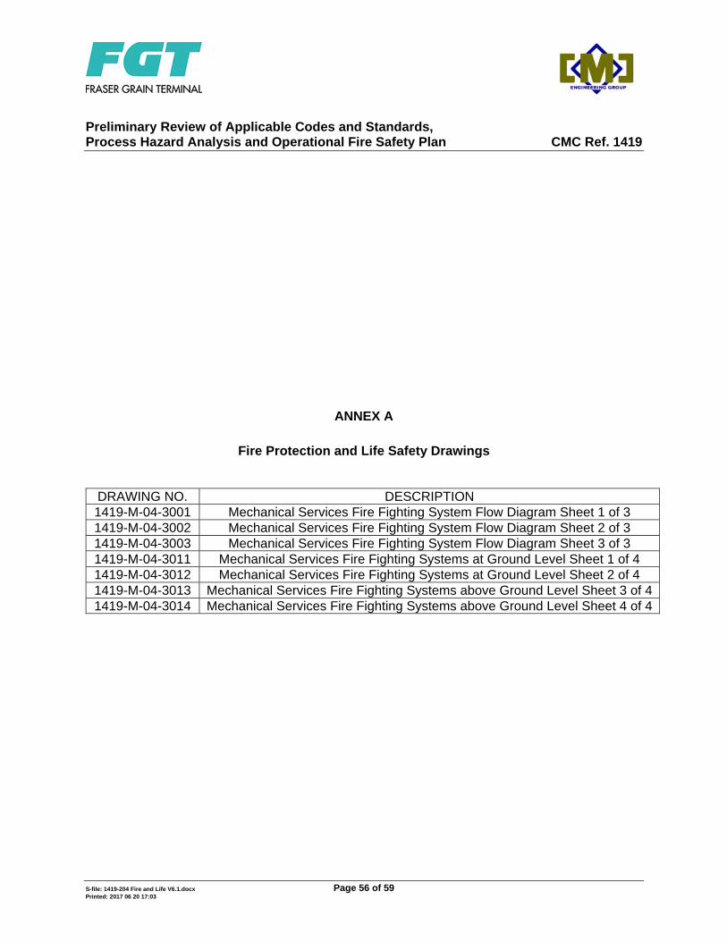
Preliminary Review of Applicable Codes and Standards, Process Hazard Analysis and Operational Fire Safety Plan CMC Ref. 1419
S-file: 1419-204 Fire and Life V6.1.docx Page 56 of 59 Printed: 2017 06 20 17:03
ANNEX A
Fire Protection and Life Safety Drawings
DRAWING NO. DESCRIPTION 1419-M-04-3001 Mechanical Services Fire Fighting System Flow Diagram Sheet 1 of 3 1419-M-04-3002 Mechanical Services Fire Fighting System Flow Diagram Sheet 2 of 3 1419-M-04-3003 Mechanical Services Fire Fighting System Flow Diagram Sheet 3 of 3 1419-M-04-3011 Mechanical Services Fire Fighting Systems at Ground Level Sheet 1 of 4 1419-M-04-3012 Mechanical Services Fire Fighting Systems at Ground Level Sheet 2 of 4 1419-M-04-3013 Mechanical Services Fire Fighting Systems above Ground Level Sheet 3 of 4 1419-M-04-3014 Mechanical Services Fire Fighting Systems above Ground Level Sheet 4 of 4
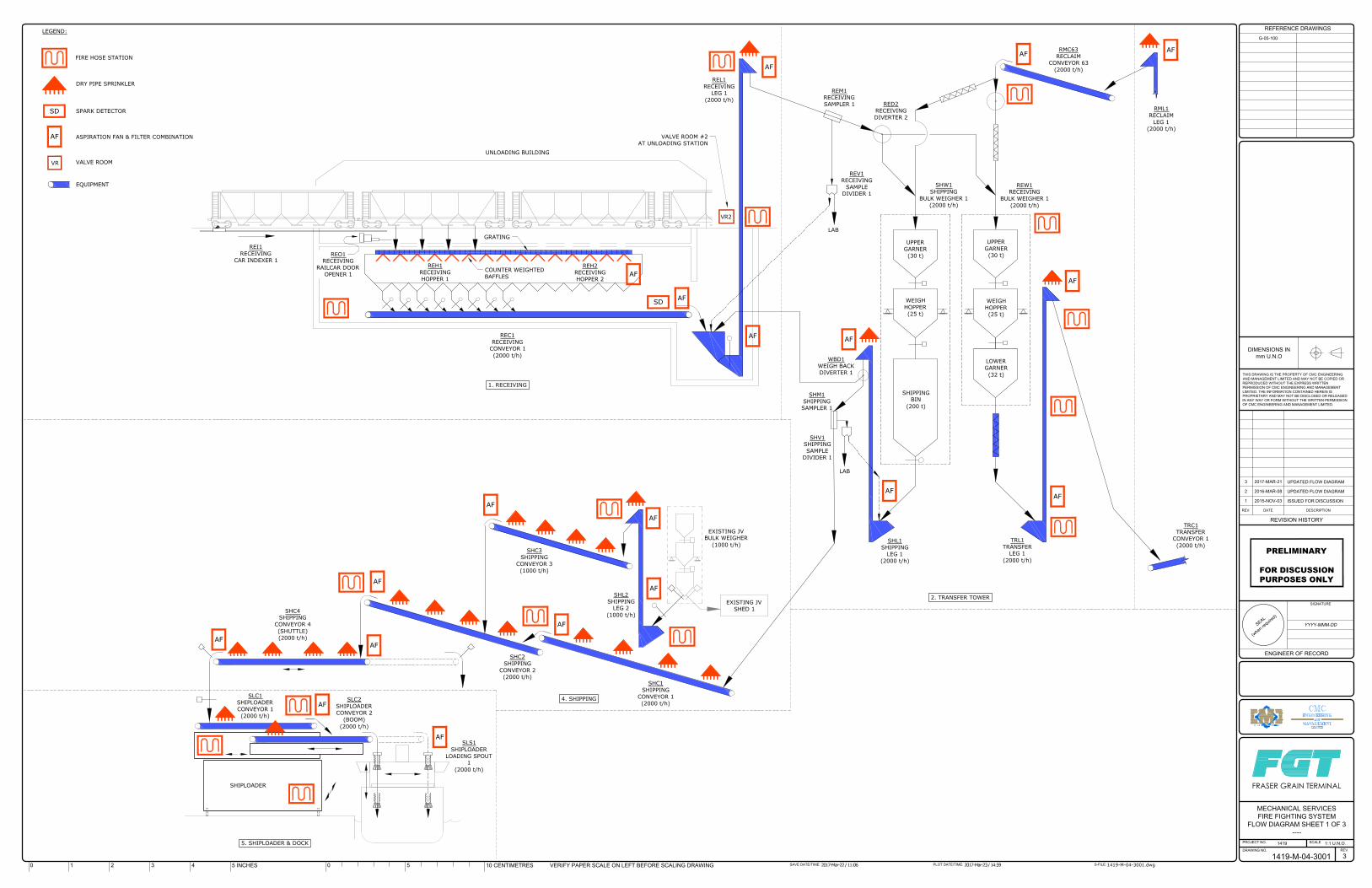
UPPER
GARNER
(30 t)
WEIGH
HOPPER
(25 t)
UPPER
GARNER
(30 t)
WEIGH
HOPPER
(25 t)
SHIPPING
BIN
(200 t)
LOWER
GARNER
(32 t)
UNLOADING BUILDING
REI1
RECEIVING
CAR INDEXER 1
LAB
1. RECEIVING
4. SHIPPING
2. TRANSFER TOWER
REO1
RECEIVING
RAILCAR DOOR
OPENER 1
REH1
RECEIVING
HOPPER 1
REH2
RECEIVING
HOPPER 2
REL1
RECEIVING
LEG 1
(2000 t/h)
REC1
RECEIVING
CONVEYOR 1
(2000 t/h)
RMC63
RECLAIM
CONVEYOR 63
(2000 t/h)
SHL1
SHIPPING
LEG 1
(2000 t/h)
REW1
RECEIVING
BULK WEIGHER 1
(2000 t/h)
TRL1
TRANSFER
LEG 1
(2000 t/h)
SHC1
SHIPPING
CONVEYOR 1
(2000 t/h)
SHC2
SHIPPING
CONVEYOR 2
(2000 t/h)
SHC3
SHIPPING
CONVEYOR 3
(1000 t/h)
SHC4
SHIPPING
CONVEYOR 4
(SHUTTLE)
(2000 t/h)
SHL2
SHIPPING
LEG 2
(1000 t/h)
SLC1
SHIPLOADER
CONVEYOR 1
(2000 t/h)
5. SHIPLOADER & DOCK
FIRE HOSE STATION
TRC1
TRANSFER
CONVEYOR 1
(2000 t/h)
RML1
RECLAIM
LEG 1
(2000 t/h)
LEGEND:
GRATING
COUNTER WEIGHTED
BAFFLES
DRY PIPE SPRINKLER
SPARK DETECTOR
SD
SD
VR2
AF
AF ASPIRATION FAN & FILTER COMBINATION
AF
AF
AF
AF
AF
AF
AF
AF
AF
AF
AF
AF
AF
AF
AF
AF
AF
AF
VR
VALVE ROOM
VALVE ROOM #2
AT UNLOADING STATION
EQUIPMENT
LAB
RED2
RECEIVING
DIVERTER 2
REM1
RECEIVING
SAMPLER 1
REV1
RECEIVING
SAMPLE
DIVIDER 1
SHW1
SHIPPING
BULK WEIGHER 1
(2000 t/h)
SHM1
SHIPPING
SAMPLER 1
SHV1
SHIPPING
SAMPLE
DIVIDER 1
EXISTING JV
BULK WEIGHER
(1000 t/h)
EXISTING JV
SHED 1
SHIPLOADER
SLC2
SHIPLOADER
CONVEYOR 2
(BOOM)
(2000 t/h)
SLS1
SHIPLOADER
LOADING SPOUT
1
(2000 t/h)
WBD1
WEIGH BACK
DIVERTER 1
1 2015-NOV-03 ISSUED FOR DISCUSSION
2 2016-MAR-08 UPDATED FLOW DIAGRAM
3 2017-MAR-21 UPDATED FLOW DIAGRAM
1419-M-04-3001.dwg2017-Mar-22 / 11:06 2017-Mar-23 / 14:59
1419-M-04-3001
1419 1:1 U.N.O.
MECHANICAL SERVICES
FIRE FIGHTING SYSTEM
FLOW DIAGRAM SHEET 1 OF 3
----
3
YYYY-MMM-DD
PRELIMINARY
FOR DISCUSSIONPURPOSES ONLY
G-05-100
S
E
A
L
(
w
h
e
n
r
e
q
u
i
r
e
d
)
THIS DRAWING IS THE PROPERTY OF CMC ENGINEERING
AND MANAGEMENT LIMITED AND MAY NOT BE COPIED OR
REPRODUCED WITHOUT THE EXPRESS WRITTEN
PERMISSION OF CMC ENGINEERING AND MANAGEMENT
LIMITED. THE INFORMATION CONTAINED HEREIN IS
PROPRIETARY AND MAY NOT BE DISCLOSED OR RELEASED
IN ANY WAY OR FORM WITHOUT THE WRITTEN PERMISSION
OF CMC ENGINEERING AND MANAGEMENT LIMITED.
DIMENSIONS IN
mm U.N.O
PROJECT NO.
DRAWING NO.
SCALE
REV.
S-FILE:PLOT DATE/TIME:SAVE DATE/TIME:
REVISION HISTORY
DESCRIPTIONDATEREV.
REFERENCE DRAWINGS
VERIFY PAPER SCALE ON LEFT BEFORE SCALING DRAWING10 CENTIMETRES505 INCHES43210
SIGNATURE
ENGINEER OF RECORD
FRASER GRAIN TERMINAL
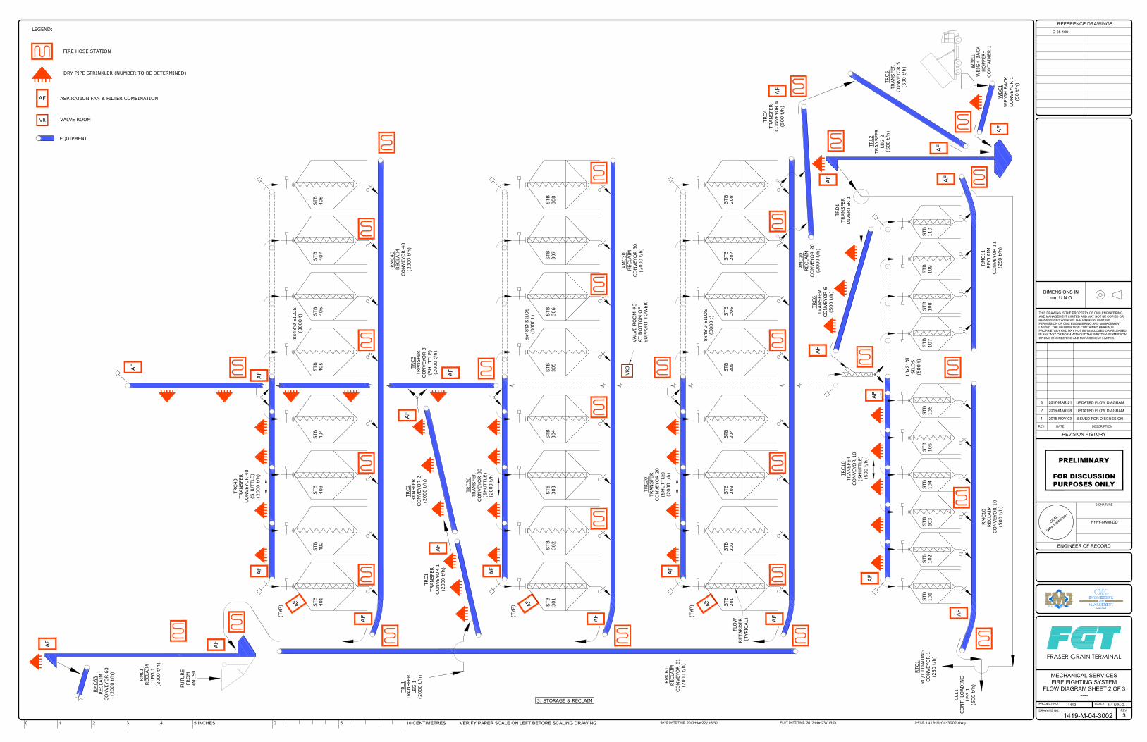
AF
3. STORAGE & RECLAIM
FIRE HOSE STATION
LEGEND:
DRY PIPE SPRINKLER (NUMBER TO BE DETERMINED)
FLO
W
RETARD
ER
(TYPICAL)
8x48'Ø
SILO
S
(3000 t)
STB
101
RM
C63
RECLAIM
CO
NVEYO
R 63
(2000 t/h)
TRL1
TRAN
SFER
LEG
1
(2000 t/h)
RM
C11
RECLAIM
CO
NVEYO
R 11
(250 t/h)
RM
C20
RECLAIM
CO
NVEYO
R 20
(2000 t/h)
RM
C30
RECLAIM
CO
NVEYO
R 30
(2000 t/h)
RM
C40
RECLAIM
CO
NVEYO
R 40
(2000 t/h)
RM
C61
RECLAIM
CO
NVEYO
R 61
(2000 t/h)
RM
L1
RECLAIM
LEG
1
(2000 t/h)
STB
102
STB
103
STB
104
STB
105
STB
106
STB
107
STB
108
STB
109
STB
110
STB
201
STB
202
STB
203
STB
204
STB
205
STB
206
STB
207
STB
208
STB
301
STB
302
STB
303
STB
304
STB
305
STB
306
STB
307
STB
308
STB
401
STB
402
STB
403
STB
404
STB
405
STB
406
STB
407
STB
408
8x48'Ø
SILO
S
(3000 t)
TRC1
TRAN
SFER
CO
NVEYO
R 1
(2000 t/h)
TRC2
TRAN
SFER
CO
NVEYO
R 2
(2000 t/h)
TRC20
TRAN
SFER
CO
NVEYO
R 20
(SH
UTTLE)
(2000 t/h)
TRC30
TRAN
SFER
CO
NVEYO
R 30
(SH
UTTLE)
(2000 t/h)
TRC40
TRAN
SFER
CO
NVEYO
R 40
(SH
UTTLE)
(2000 t/h)
TRC3
TRAN
SFER
CO
NVEYO
R 3
(SH
UTTLE)
(2000 t/h)
TRC10
TRAN
SFER
CO
NVEYO
R 10
(SH
UTTLE)
(500 t/h)
10x21'Ø
SILO
S
(500 t)
RM
C10
RECLAIM
CO
NVEYO
R 10
(500 t/h)
8x48'Ø
SILO
S
(3000 t)
AF
AF
AF
A
F
(TYP)
A
F
(TYP)
A
F
(TYP)
AF
AF
AF
AF
AF
AF
AF
AF
AF
AF
AF
AF
VR3
AF ASPIRATION FAN & FILTER COMBINATION
VR
VALVE ROOM
VALVE RO
OM
#
3
AT BO
TTO
M O
F
SU
PPO
RT TO
WER
EQUIPMENT
TRC6
TRAN
SFER
CO
NVEYO
R 6
(500 t/h)
TRL2
TRAN
SFER
LEG
2
(500 t/h)
TRC4
TRAN
SFER
CO
NVEYO
R 4
(500 t/h)
TRD
1
TRAN
SFER
DIVERTER 1
AF
AF
AF
AF
RTC1
RC/T LO
AD
IN
G
CO
NVEYO
R 1
(250 t/h)
CLL1
CO
NT. LO
AD
IN
G
LEG
1
(500 t/h)
WBH
1
WEIG
H BACK
HO
PPER-
CO
NTAIN
ER 1
TRC5
TRAN
SFER
CO
NVEYO
R 5
(500 t/h)
WBC1
WEIG
H BACK
CO
NVEYO
R 1
(50 t/h)
AF
AF
FU
TU
RE
FRO
M
RM
C50
1 2015-NOV-03 ISSUED FOR DISCUSSION
2 2016-MAR-08 UPDATED FLOW DIAGRAM
3 2017-MAR-21 UPDATED FLOW DIAGRAM
1419-M-04-3002.dwg2017-Mar-22 / 16:50 2017-Mar-23 / 15:01
1419-M-04-3002
1419 1:1 U.N.O.
MECHANICAL SERVICES
FIRE FIGHTING SYSTEM
FLOW DIAGRAM SHEET 2 OF 3
----
3
YYYY-MMM-DD
PRELIMINARY
FOR DISCUSSIONPURPOSES ONLY
G-05-100
S
E
A
L
(
w
h
e
n
r
e
q
u
i
r
e
d
)
THIS DRAWING IS THE PROPERTY OF CMC ENGINEERING
AND MANAGEMENT LIMITED AND MAY NOT BE COPIED OR
REPRODUCED WITHOUT THE EXPRESS WRITTEN
PERMISSION OF CMC ENGINEERING AND MANAGEMENT
LIMITED. THE INFORMATION CONTAINED HEREIN IS
PROPRIETARY AND MAY NOT BE DISCLOSED OR RELEASED
IN ANY WAY OR FORM WITHOUT THE WRITTEN PERMISSION
OF CMC ENGINEERING AND MANAGEMENT LIMITED.
DIMENSIONS IN
mm U.N.O
PROJECT NO.
DRAWING NO.
SCALE
REV.
S-FILE:PLOT DATE/TIME:SAVE DATE/TIME:
REVISION HISTORY
DESCRIPTIONDATEREV.
REFERENCE DRAWINGS
VERIFY PAPER SCALE ON LEFT BEFORE SCALING DRAWING10 CENTIMETRES505 INCHES43210
SIGNATURE
ENGINEER OF RECORD
FRASER GRAIN TERMINAL
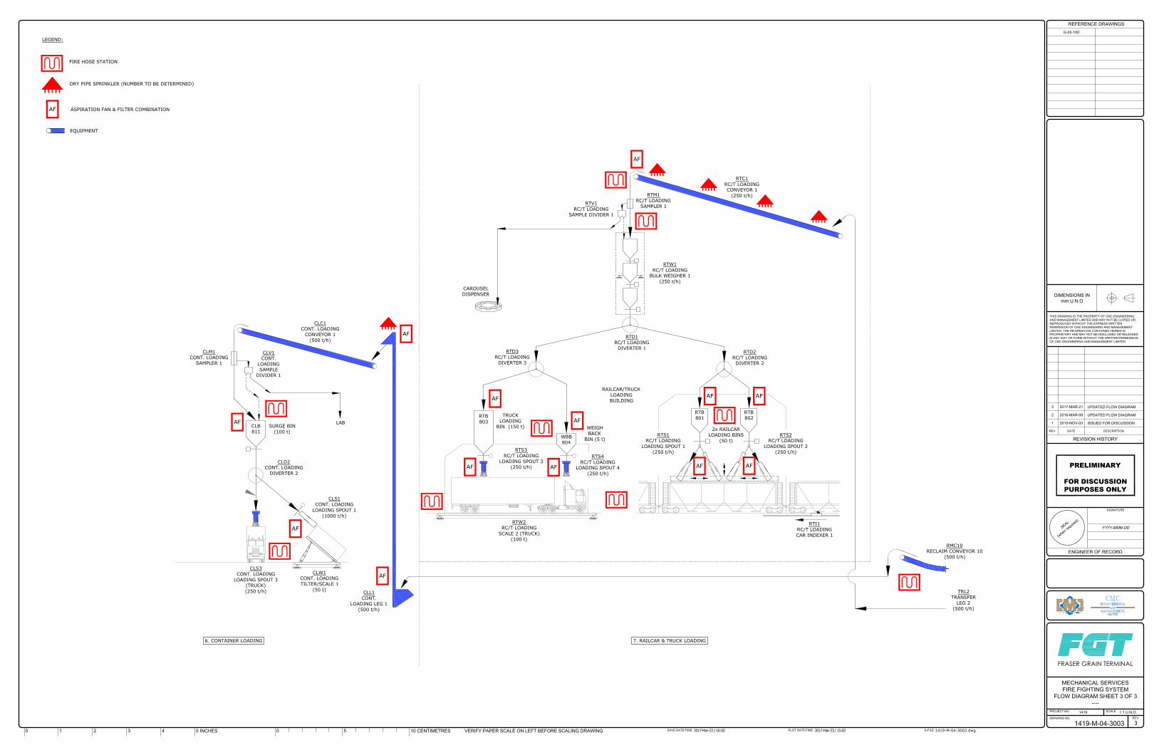
FIRE HOSE STATION
LEGEND:
DRY PIPE SPRINKLER (NUMBER TO BE DETERMINED)
AF ASPIRATION FAN & FILTER COMBINATION
EQUIPMENT
2x RAILCAR
LOADING BINS
(50 t)
RAILCAR/TRUCK
LOADING
BUILDING
CAROUSEL
DISPENSER
TRUCK
LOADING
BIN (150 t)
WEIGH
BACK
BIN (5 t)
RTB
802
RTB
801
RTB
803
RTD1
RC/T LOADING
DIVERTER 1
WBB
804
RTD3
RC/T LOADING
DIVERTER 3
RTD2
RC/T LOADING
DIVERTER 2
RTI1
RC/T LOADING
CAR INDEXER 1
RTM1
RC/T LOADING
SAMPLER 1
RTS2
RC/T LOADING
LOADING SPOUT 2
(250 t/h)
RTS1
RC/T LOADING
LOADING SPOUT 1
(250 t/h)
RTS3
RC/T LOADING
LOADING SPOUT 3
(250 t/h)
RTS4
RC/T LOADING
LOADING SPOUT 4
(250 t/h)
RTV1
RC/T LOADING
SAMPLE DIVIDER 1
RTW1
RC/T LOADING
BULK WEIGHER 1
(250 t/h)
RTW2
RC/T LOADING
SCALE 2 (TRUCK)
(100 t)
RTC1
RC/T LOADING
CONVEYOR 1
(250 t/h)
CLC1
CONT. LOADING
CONVEYOR 1
(500 t/h)
SURGE BIN
(100 t)
CLB
811
CLM1
CONT. LOADING
SAMPLER 1
CLD2
CONT. LOADING
DIVERTER 2
CLL1
CONT.
LOADING LEG 1
(500 t/h)
CLS1
CONT. LOADING
LOADING SPOUT 1
(1000 t/h)
CLS3
CONT. LOADING
LOADING SPOUT 3
(TRUCK)
(250 t/h)
CLW1
CONT. LOADING
TILTER/SCALE 1
(50 t)
LAB
CLV1
CONT.
LOADING
SAMPLE
DIVIDER 1
RMC10
RECLAIM CONVEYOR 10
(500 t/h)
TRL2
TRANSFER
LEG 2
(500 t/h)
AF
AF
AF AF
AF
AF
AF
AF
AF
AF
AF
AF
AF
6. CONTAINER LOADING 7. RAILCAR & TRUCK LOADING
1 2015-NOV-03 ISSUED FOR DISCUSSION
2 2016-MAR-08 UPDATED FLOW DIAGRAM
3 2017-MAR-21 UPDATED FLOW DIAGRAM
1419-M-04-3003.dwg2017-Mar-22 / 16:50 2017-Mar-23 / 15:02
1419-M-04-3003
1419 1:1 U.N.O.
MECHANICAL SERVICES
FIRE FIGHTING SYSTEM
FLOW DIAGRAM SHEET 3 OF 3
----
3
YYYY-MMM-DD
PRELIMINARY
FOR DISCUSSIONPURPOSES ONLY
G-05-100
S
E
A
L
(
w
h
e
n
r
e
q
u
i
r
e
d
)
THIS DRAWING IS THE PROPERTY OF CMC ENGINEERING
AND MANAGEMENT LIMITED AND MAY NOT BE COPIED OR
REPRODUCED WITHOUT THE EXPRESS WRITTEN
PERMISSION OF CMC ENGINEERING AND MANAGEMENT
LIMITED. THE INFORMATION CONTAINED HEREIN IS
PROPRIETARY AND MAY NOT BE DISCLOSED OR RELEASED
IN ANY WAY OR FORM WITHOUT THE WRITTEN PERMISSION
OF CMC ENGINEERING AND MANAGEMENT LIMITED.
DIMENSIONS IN
mm U.N.O
PROJECT NO.
DRAWING NO.
SCALE
REV.
S-FILE:PLOT DATE/TIME:SAVE DATE/TIME:
REVISION HISTORY
DESCRIPTIONDATEREV.
REFERENCE DRAWINGS
VERIFY PAPER SCALE ON LEFT BEFORE SCALING DRAWING10 CENTIMETRES505 INCHES43210
SIGNATURE
ENGINEER OF RECORD
FRASER GRAIN TERMINAL
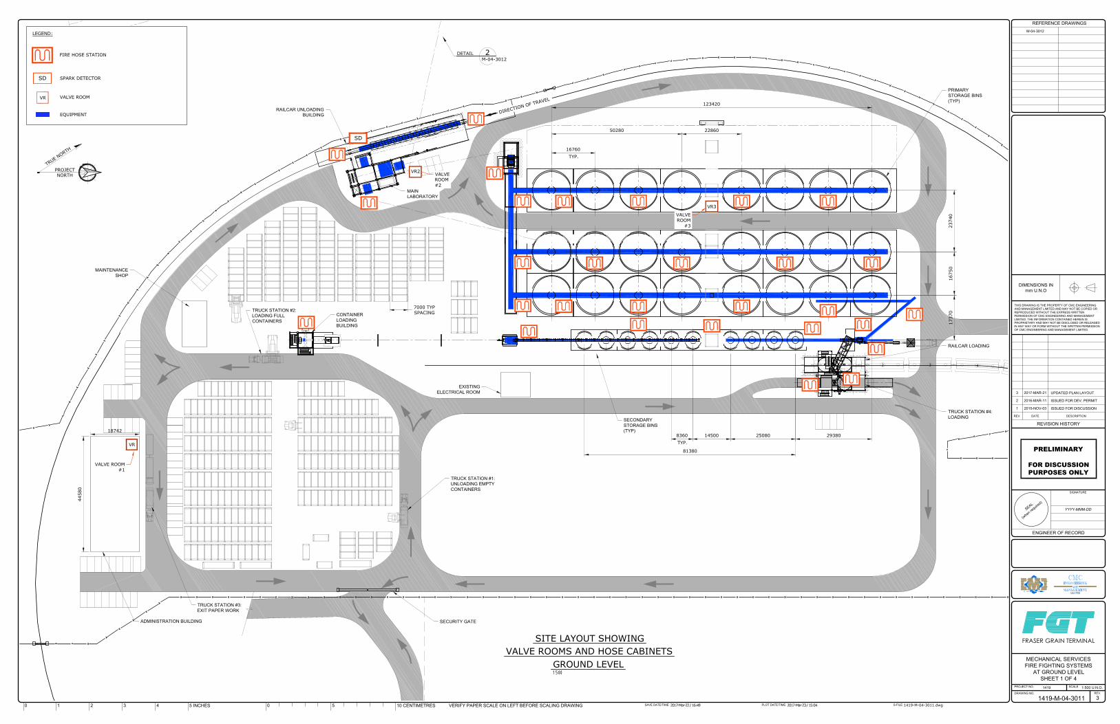
1 2 3
4
S
E
A
L
(
w
h
e
n
r
e
q
u
i
r
e
d
)
THIS DRAWING IS THE PROPERTY OF CMC ENGINEERING
AND MANAGEMENT LIMITED AND MAY NOT BE COPIED OR
REPRODUCED WITHOUT THE EXPRESS WRITTEN
PERMISSION OF CMC ENGINEERING AND MANAGEMENT
LIMITED. THE INFORMATION CONTAINED HEREIN IS
PROPRIETARY AND MAY NOT BE DISCLOSED OR RELEASED
IN ANY WAY OR FORM WITHOUT THE WRITTEN PERMISSION
OF CMC ENGINEERING AND MANAGEMENT LIMITED.
DIMENSIONS IN
mm U.N.O
PROJECT NO.
DRAWING NO.
SCALE
REV.
S-FILE:PLOT DATE/TIME:SAVE DATE/TIME:
REVISION HISTORY
DESCRIPTIONDATEREV.
REFERENCE DRAWINGS
VERIFY PAPER SCALE ON LEFT BEFORE SCALING DRAWING10 CENTIMETRES505 INCHES43210
SIGNATURE
ENGINEER OF RECORD
FRASER GRAIN TERMINAL
1 2015-NOV-03 ISSUED FOR DISCUSSION
2 2016-MAR-11 ISSUED FOR DEV. PERMIT
3 2017-MAR-21 UPDATED PLAN LAYOUT
1419-M-04-3011.dwg2017-Mar-22 / 16:49 2017-Mar-23 / 15:04
1419-M-04-3011
1419 1:500 U.N.O.
MECHANICAL SERVICES
FIRE FIGHTING SYSTEMS
AT GROUND LEVEL
SHEET 1 OF 4
3
YYYY-MMM-DD
PRELIMINARY
FOR DISCUSSIONPURPOSES ONLY
M-04-3012
VALVE ROOMS AND HOSE CABINETS
SITE LAYOUT SHOWING
GROUND LEVEL
FIRE HOSE STATION
LEGEND:
SPARK DETECTORSD
VR
VALVE ROOM
EQUIPMENT
T
R
U
E
N
O
R
T
H
PROJECT
NORTH
MAIN
LABORATORY
RAILCAR UNLOADING
BUILDING
D
I
R
E
C
T
I
O
N
O
F
T
R
A
V
E
L
DETAIL 2
M-04-3012
VR2
VALVE
ROOM
#2
SD
123420
2286050280
16760
TYP.
VR3
VALVE
ROOM
#3
23740
16750
RAILCAR LOADING
PRIMARY
STORAGE BINS
(TYP)
17370
EXISTING
ELECTRICAL ROOM
81380
14500 25080 29380
SECONDARY
STORAGE BINS
(TYP)
TRUCK STATION #4:
LOADING
MAINTENANCE
SHOP
7000 TYP
SPACING
CONTAINER
LOADING
BUILDING
TRUCK STATION #2:
LOADING FULL
CONTAINERS
44580
18742
TRUCK STATION #1:
UNLOADING EMPTY
CONTAINERS
SECURITY GATE
TRUCK STATION #3:
EXIT PAPER WORK
VR
VALVE ROOM
#1
8360
TYP.
ADMINISTRATION BUILDING
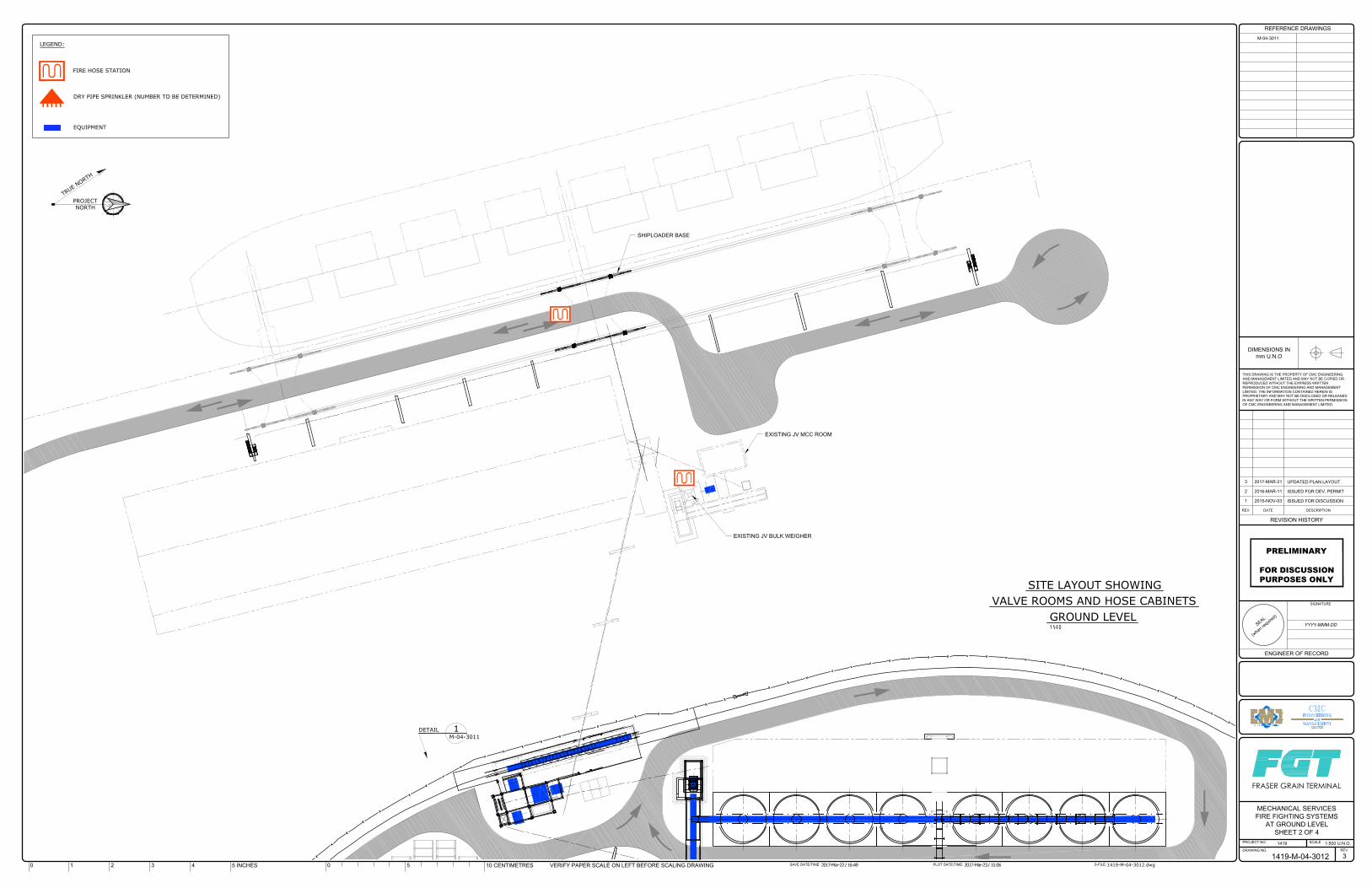
S
E
A
L
(
w
h
e
n
r
e
q
u
i
r
e
d
)
THIS DRAWING IS THE PROPERTY OF CMC ENGINEERING
AND MANAGEMENT LIMITED AND MAY NOT BE COPIED OR
REPRODUCED WITHOUT THE EXPRESS WRITTEN
PERMISSION OF CMC ENGINEERING AND MANAGEMENT
LIMITED. THE INFORMATION CONTAINED HEREIN IS
PROPRIETARY AND MAY NOT BE DISCLOSED OR RELEASED
IN ANY WAY OR FORM WITHOUT THE WRITTEN PERMISSION
OF CMC ENGINEERING AND MANAGEMENT LIMITED.
DIMENSIONS IN
mm U.N.O
PROJECT NO.
DRAWING NO.
SCALE
REV.
S-FILE:PLOT DATE/TIME:SAVE DATE/TIME:
REVISION HISTORY
DESCRIPTIONDATEREV.
REFERENCE DRAWINGS
VERIFY PAPER SCALE ON LEFT BEFORE SCALING DRAWING10 CENTIMETRES505 INCHES43210
SIGNATURE
ENGINEER OF RECORD
FRASER GRAIN TERMINAL
1 2015-NOV-03 ISSUED FOR DISCUSSION
2 2016-MAR-11 ISSUED FOR DEV. PERMIT
3 2017-MAR-21 UPDATED PLAN LAYOUT
1419-M-04-3012.dwg2017-Mar-22 / 16:49 2017-Mar-23 / 15:06
1419-M-04-3012
1419 1:500 U.N.O.
MECHANICAL SERVICES
FIRE FIGHTING SYSTEMS
AT GROUND LEVEL
SHEET 2 OF 4
3
YYYY-MMM-DD
PRELIMINARY
FOR DISCUSSIONPURPOSES ONLY
M-04-3011
VALVE ROOMS AND HOSE CABINETS
SITE LAYOUT SHOWING
GROUND LEVEL
T
R
U
E
N
O
R
T
H
PROJECT
NORTH
FIRE HOSE STATION
LEGEND:
DRY PIPE SPRINKLER (NUMBER TO BE DETERMINED)
EQUIPMENT
SHIPLOADER BASE
EXISTING JV MCC ROOM
EXISTING JV BULK WEIGHER
DETAIL 1
M-04-3011
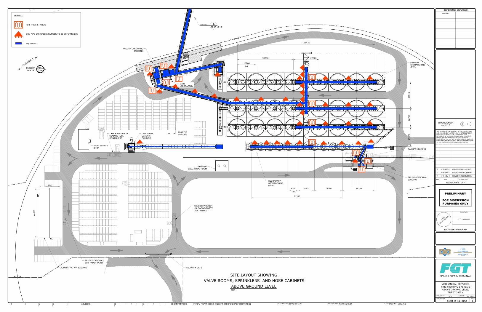
1 2 3
4
S
E
A
L
(
w
h
e
n
r
e
q
u
i
r
e
d
)
THIS DRAWING IS THE PROPERTY OF CMC ENGINEERING
AND MANAGEMENT LIMITED AND MAY NOT BE COPIED OR
REPRODUCED WITHOUT THE EXPRESS WRITTEN
PERMISSION OF CMC ENGINEERING AND MANAGEMENT
LIMITED. THE INFORMATION CONTAINED HEREIN IS
PROPRIETARY AND MAY NOT BE DISCLOSED OR RELEASED
IN ANY WAY OR FORM WITHOUT THE WRITTEN PERMISSION
OF CMC ENGINEERING AND MANAGEMENT LIMITED.
DIMENSIONS IN
mm U.N.O
PROJECT NO.
DRAWING NO.
SCALE
REV.
S-FILE:PLOT DATE/TIME:SAVE DATE/TIME:
REVISION HISTORY
DESCRIPTIONDATEREV.
REFERENCE DRAWINGS
VERIFY PAPER SCALE ON LEFT BEFORE SCALING DRAWING10 CENTIMETRES505 INCHES43210
SIGNATURE
ENGINEER OF RECORD
FRASER GRAIN TERMINAL
1 2015-NOV-03 ISSUED FOR DISCUSSION
2 2016-MAR-11 ISSUED FOR DEV. PERMIT
3 2017-MAR-21 UPDATED PLAN LAYOUT
1419-M-04-3013.dwg2017-Mar-22 / 16:49 2017-Mar-23 / 15:09
1419-M-04-3013
1419 1:500 U.N.O.
MECHANICAL SERVICES
FIRE FIGHTING SYSTEMS
ABOVE GROUND LEVEL
SHEET 3 OF 4
3
YYYY-MMM-DD
PRELIMINARY
FOR DISCUSSIONPURPOSES ONLY
M-04-3014
VALVE ROOMS, SPRINKLERS AND HOSE CABINETS
SITE LAYOUT SHOWING
ABOVE GROUND LEVEL
T
R
U
E
N
O
R
T
H
PROJECT
NORTH
FIRE HOSE STATION
LEGEND:
DRY PIPE SPRINKLER (NUMBER TO BE DETERMINED)
EQUIPMENT
MAIN
LABORATORY
RAILCAR UNLOADING
BUILDING
DETAIL 4
M-04-3014
123420
2286050280
PRIMARY
STORAGE BINS
(TYP)
16760
TYP.
23740
16750
81380
14500 25080 29380
SECONDARY
STORAGE BINS
(TYP)
RAILCAR LOADING
TRUCK STATION #4:
LOADING
17370
EXISTING
ELECTRICAL ROOM
MAINTENANCE
SHOP
ADMINISTRATION BUILDING
7000 TYP
SPACING
44580
18742
CONTAINER
LOADING
BUILDING
TRUCK STATION #2:
LOADING FULL
CONTAINERS
TRUCK STATION #1:
UNLOADING EMPTY
CONTAINERS
SECURITY GATE
TRUCK STATION #3:
EXIT PAPER WORK
8360
TYP.
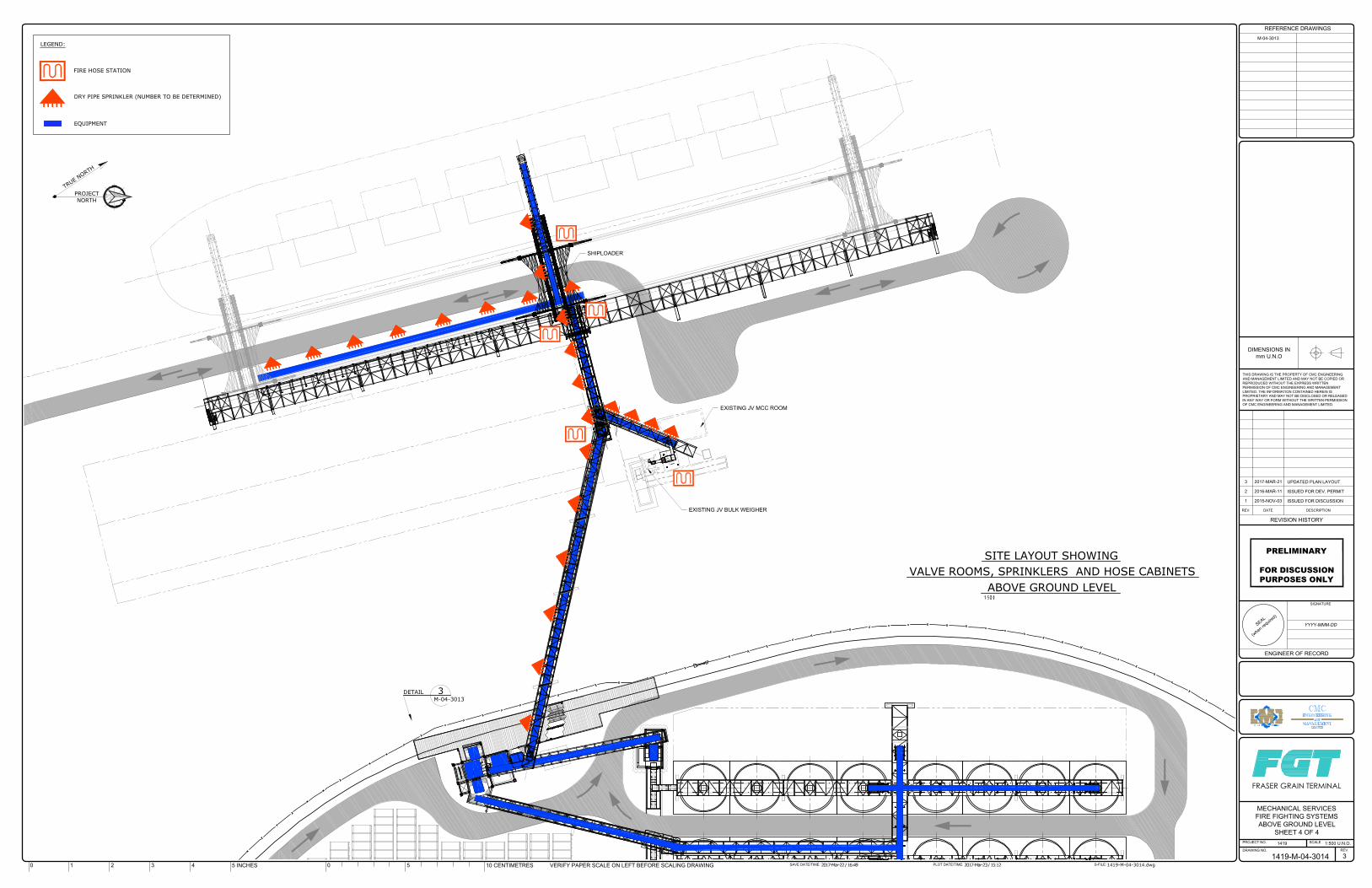
S
E
A
L
(
w
h
e
n
r
e
q
u
i
r
e
d
)
THIS DRAWING IS THE PROPERTY OF CMC ENGINEERING
AND MANAGEMENT LIMITED AND MAY NOT BE COPIED OR
REPRODUCED WITHOUT THE EXPRESS WRITTEN
PERMISSION OF CMC ENGINEERING AND MANAGEMENT
LIMITED. THE INFORMATION CONTAINED HEREIN IS
PROPRIETARY AND MAY NOT BE DISCLOSED OR RELEASED
IN ANY WAY OR FORM WITHOUT THE WRITTEN PERMISSION
OF CMC ENGINEERING AND MANAGEMENT LIMITED.
DIMENSIONS IN
mm U.N.O
PROJECT NO.
DRAWING NO.
SCALE
REV.
S-FILE:PLOT DATE/TIME:SAVE DATE/TIME:
REVISION HISTORY
DESCRIPTIONDATEREV.
REFERENCE DRAWINGS
VERIFY PAPER SCALE ON LEFT BEFORE SCALING DRAWING10 CENTIMETRES505 INCHES43210
SIGNATURE
ENGINEER OF RECORD
FRASER GRAIN TERMINAL
1 2015-NOV-03 ISSUED FOR DISCUSSION
2 2016-MAR-11 ISSUED FOR DEV. PERMIT
3 2017-MAR-21 UPDATED PLAN LAYOUT
1419-M-04-3014.dwg2017-Mar-22 / 16:49 2017-Mar-23 / 15:12
1419-M-04-3014
1419 1:500 U.N.O.
MECHANICAL SERVICES
FIRE FIGHTING SYSTEMS
ABOVE GROUND LEVEL
SHEET 4 OF 4
3
YYYY-MMM-DD
PRELIMINARY
FOR DISCUSSIONPURPOSES ONLY
M-04-3013
VALVE ROOMS, SPRINKLERS AND HOSE CABINETS
SITE LAYOUT SHOWING
ABOVE GROUND LEVEL
T
R
U
E
N
O
R
T
H
PROJECT
NORTH
FIRE HOSE STATION
LEGEND:
DRY PIPE SPRINKLER (NUMBER TO BE DETERMINED)
EQUIPMENT
SHIPLOADER
DETAIL 3
M-04-3013
EXISTING JV MCC ROOM
EXISTING JV BULK WEIGHER
Preliminary Review of Applicable Codes and Standards, Process Hazard Analysis and Operational Fire Safety Plan CMC Ref. 1419
S-file: 1419-204 Fire and Life V6.1.docx Page 57 of 59 Printed: 2017 06 20 17:03
ANNEX B
Factory Mutual Data Sheets
DESCRIPTION Factory Mutual Data Sheet FMDS 7-11: Belt Conveyors
Factory Mutual Data Sheet FMDS 7-75: Grain Storage and Milling
The documents contained in the following attachment were chronologically relevant at the time of the first draft of this report (early 2016). Some time has expired since then and the most recent edition of these FM documents may be somewhat different than what is presented here in. The FGT design process will, in all instances, refer to the contemporary versions of all applicable codes and standards. The start of the detailed engineering phase will include a review of all of these applicable documents; the current revision levels will then be compared to those used during the preliminary engineering stage. Decisions will be made as follows:
# Result of Code and Standard Review
Action
1 Version still valid and in force. No change in design. 2 Version updated and in force. Review code/guideline changes to determine if
design changes are required. Make design changes as applicable.
3 Version updated but pending (not yet in force).
Review code/guideline changes to determine if design changes would be required.
Make recommendations to client regarding possible early adoption of (some) new rules and guidelines.
January 2012Page 1 of 12
BELT CONVEYORS
Table of ContentsPage
1.0 SCOPE .................................................................................................................................................... 21.1 Changes ........................................................................................................................................... 2
2.0 LOSS PREVENTION RECOMMENDATIONS ........................................................................................ 22.1 Construction and Location ............................................................................................................... 22.2 Occupancy ........................................................................................................................................ 22.3 Protection ......................................................................................................................................... 2
2.3.1 General ................................................................................................................................... 22.3.2 Indoor Conveyors ................................................................................................................... 32.3.3 Outdoor Conveyors ................................................................................................................ 32.3.4 Specialty Conveyors .............................................................................................................. 72.3.5 Explosion Protection .............................................................................................................. 82.3.6 Manual Protection .................................................................................................................. 8
2.4 Utilities .............................................................................................................................................. 92.5 Operation and Maintenance ............................................................................................................. 92.6 Ignition Source Control ..................................................................................................................... 9
3.0 SUPPORT FOR RECOMMENDATIONS .............................................................................................. 103.1 Belt Flammability ............................................................................................................................ 10
3.1.1 General .................................................................................................................................. 103.1.2 Laboratory-Scale Testing ....................................................................................................... 10
3.2 Major Factors Affecting the Need for Fire Protection ...................................................................... 104.0 REFERENCES ....................................................................................................................................... 11
4.1 FM Global ....................................................................................................................................... 114.2 Other ............................................................................................................................................... 12
APPENDIX A GLOSSARY OF TERMS ....................................................................................................... 12APPENDIX B DOCUMENT REVISION HISTORY ...................................................................................... 12
List of FiguresFig. 1a. Decision tree to determine need for automatic sprinkler protection for outdoor conveyors ............ 4Fig. 1b. Decision tree to determine need for automatic sprinkler protection for outdoor conveyors ............ 5Fig. 2a. Suggested locations for automatic sprinklers in various outdoor conveyor arrangements
of combustible or noncombustible construction (The occupancy is assumed to benoncombustible, apart from the belt or conveyed product) ............................................................. 6
Fig. 2b. Suggested locations for automatic sprinklers in various outdoor conveyor arrangementsof combustible or noncombustible construction (The occupancy is assumed to benoncombustible, apart from the belt or conveyed product) ............................................................. 6
List of TablesTable 1. Automatic Sprinkler Spacing for Enclosed and Partially Enclosed Indoor Conveyors ..................... 3
FM GlobalProperty Loss Prevention Data Sheets 7-11
©2009 Factory Mutual Insurance Company. All rights reserved. No part of this document may be reproduced,stored in a retrieval system, or transmitted, in whole or in part, in any form or by any means, electronic, mechanical,photocopying, recording, or otherwise, without written permission of Factory Mutual Insurance Company.
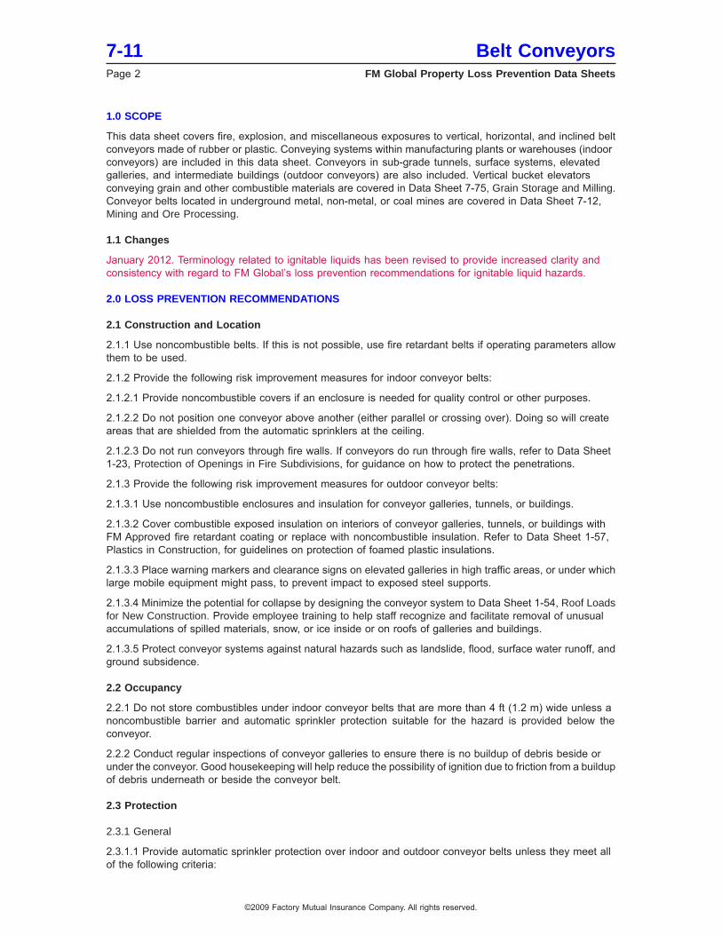
1.0 SCOPE
This data sheet covers fire, explosion, and miscellaneous exposures to vertical, horizontal, and inclined beltconveyors made of rubber or plastic. Conveying systems within manufacturing plants or warehouses (indoorconveyors) are included in this data sheet. Conveyors in sub-grade tunnels, surface systems, elevatedgalleries, and intermediate buildings (outdoor conveyors) are also included. Vertical bucket elevatorsconveying grain and other combustible materials are covered in Data Sheet 7-75, Grain Storage and Milling.Conveyor belts located in underground metal, non-metal, or coal mines are covered in Data Sheet 7-12,Mining and Ore Processing.
1.1 Changes
January 2012. Terminology related to ignitable liquids has been revised to provide increased clarity andconsistency with regard to FM Global’s loss prevention recommendations for ignitable liquid hazards.
2.0 LOSS PREVENTION RECOMMENDATIONS
2.1 Construction and Location
2.1.1 Use noncombustible belts. If this is not possible, use fire retardant belts if operating parameters allowthem to be used.
2.1.2 Provide the following risk improvement measures for indoor conveyor belts:
2.1.2.1 Provide noncombustible covers if an enclosure is needed for quality control or other purposes.
2.1.2.2 Do not position one conveyor above another (either parallel or crossing over). Doing so will createareas that are shielded from the automatic sprinklers at the ceiling.
2.1.2.3 Do not run conveyors through fire walls. If conveyors do run through fire walls, refer to Data Sheet1-23, Protection of Openings in Fire Subdivisions, for guidance on how to protect the penetrations.
2.1.3 Provide the following risk improvement measures for outdoor conveyor belts:
2.1.3.1 Use noncombustible enclosures and insulation for conveyor galleries, tunnels, or buildings.
2.1.3.2 Cover combustible exposed insulation on interiors of conveyor galleries, tunnels, or buildings withFM Approved fire retardant coating or replace with noncombustible insulation. Refer to Data Sheet 1-57,Plastics in Construction, for guidelines on protection of foamed plastic insulations.
2.1.3.3 Place warning markers and clearance signs on elevated galleries in high traffic areas, or under whichlarge mobile equipment might pass, to prevent impact to exposed steel supports.
2.1.3.4 Minimize the potential for collapse by designing the conveyor system to Data Sheet 1-54, Roof Loadsfor New Construction. Provide employee training to help staff recognize and facilitate removal of unusualaccumulations of spilled materials, snow, or ice inside or on roofs of galleries and buildings.
2.1.3.5 Protect conveyor systems against natural hazards such as landslide, flood, surface water runoff, andground subsidence.
2.2 Occupancy
2.2.1 Do not store combustibles under indoor conveyor belts that are more than 4 ft (1.2 m) wide unless anoncombustible barrier and automatic sprinkler protection suitable for the hazard is provided below theconveyor.
2.2.2 Conduct regular inspections of conveyor galleries to ensure there is no buildup of debris beside orunder the conveyor. Good housekeeping will help reduce the possibility of ignition due to friction from a buildupof debris underneath or beside the conveyor belt.
2.3 Protection
2.3.1 General
2.3.1.1 Provide automatic sprinkler protection over indoor and outdoor conveyor belts unless they meet allof the following criteria:
7-11 Belt ConveyorsPage 2 FM Global Property Loss Prevention Data Sheets
©2009 Factory Mutual Insurance Company. All rights reserved.
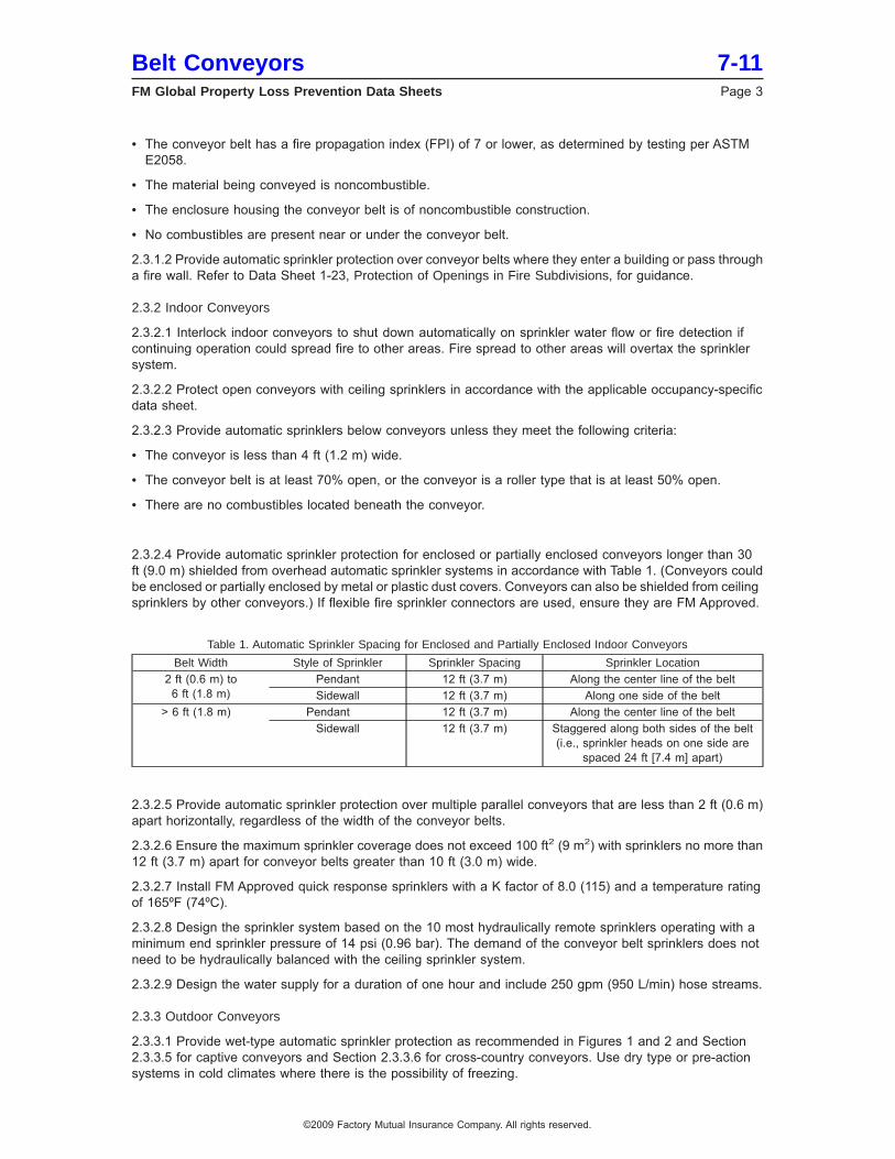
• The conveyor belt has a fire propagation index (FPI) of 7 or lower, as determined by testing per ASTME2058.
• The material being conveyed is noncombustible.
• The enclosure housing the conveyor belt is of noncombustible construction.
• No combustibles are present near or under the conveyor belt.
2.3.1.2 Provide automatic sprinkler protection over conveyor belts where they enter a building or pass througha fire wall. Refer to Data Sheet 1-23, Protection of Openings in Fire Subdivisions, for guidance.
2.3.2 Indoor Conveyors
2.3.2.1 Interlock indoor conveyors to shut down automatically on sprinkler water flow or fire detection ifcontinuing operation could spread fire to other areas. Fire spread to other areas will overtax the sprinklersystem.
2.3.2.2 Protect open conveyors with ceiling sprinklers in accordance with the applicable occupancy-specificdata sheet.
2.3.2.3 Provide automatic sprinklers below conveyors unless they meet the following criteria:
• The conveyor is less than 4 ft (1.2 m) wide.
• The conveyor belt is at least 70% open, or the conveyor is a roller type that is at least 50% open.
• There are no combustibles located beneath the conveyor.
2.3.2.4 Provide automatic sprinkler protection for enclosed or partially enclosed conveyors longer than 30ft (9.0 m) shielded from overhead automatic sprinkler systems in accordance with Table 1. (Conveyors couldbe enclosed or partially enclosed by metal or plastic dust covers. Conveyors can also be shielded from ceilingsprinklers by other conveyors.) If flexible fire sprinkler connectors are used, ensure they are FM Approved.
Table 1. Automatic Sprinkler Spacing for Enclosed and Partially Enclosed Indoor Conveyors
Belt Width Style of Sprinkler Sprinkler Spacing Sprinkler Location2 ft (0.6 m) to6 ft (1.8 m)
Pendant 12 ft (3.7 m) Along the center line of the beltSidewall 12 ft (3.7 m) Along one side of the belt
> 6 ft (1.8 m) Pendant 12 ft (3.7 m) Along the center line of the beltSidewall 12 ft (3.7 m) Staggered along both sides of the belt
(i.e., sprinkler heads on one side arespaced 24 ft [7.4 m] apart)
2.3.2.5 Provide automatic sprinkler protection over multiple parallel conveyors that are less than 2 ft (0.6 m)apart horizontally, regardless of the width of the conveyor belts.
2.3.2.6 Ensure the maximum sprinkler coverage does not exceed 100 ft2 (9 m2) with sprinklers no more than12 ft (3.7 m) apart for conveyor belts greater than 10 ft (3.0 m) wide.
2.3.2.7 Install FM Approved quick response sprinklers with a K factor of 8.0 (115) and a temperature ratingof 165ºF (74ºC).
2.3.2.8 Design the sprinkler system based on the 10 most hydraulically remote sprinklers operating with aminimum end sprinkler pressure of 14 psi (0.96 bar). The demand of the conveyor belt sprinklers does notneed to be hydraulically balanced with the ceiling sprinkler system.
2.3.2.9 Design the water supply for a duration of one hour and include 250 gpm (950 L/min) hose streams.
2.3.3 Outdoor Conveyors
2.3.3.1 Provide wet-type automatic sprinkler protection as recommended in Figures 1 and 2 and Section2.3.3.5 for captive conveyors and Section 2.3.3.6 for cross-country conveyors. Use dry type or pre-actionsystems in cold climates where there is the possibility of freezing.
Belt Conveyors 7-11FM Global Property Loss Prevention Data Sheets Page 3
©2009 Factory Mutual Insurance Company. All rights reserved.
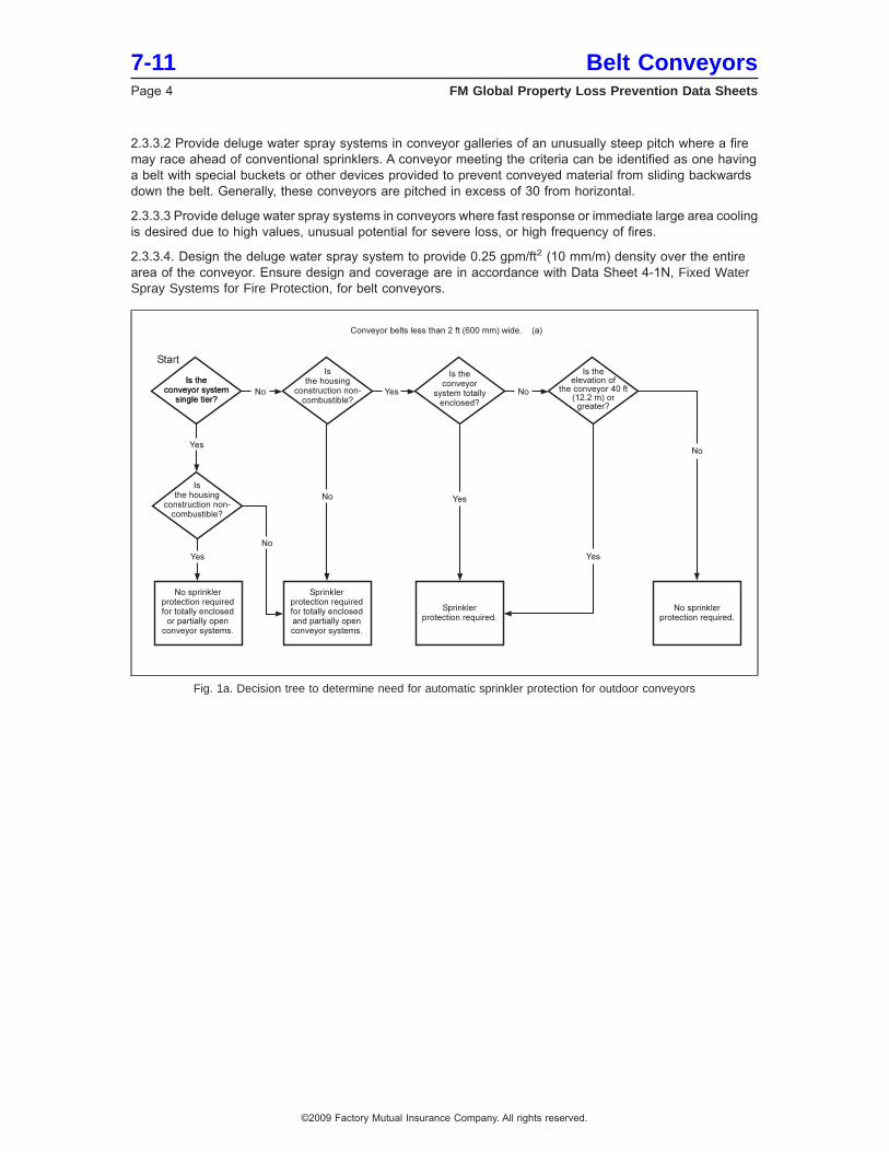
2.3.3.2 Provide deluge water spray systems in conveyor galleries of an unusually steep pitch where a firemay race ahead of conventional sprinklers. A conveyor meeting the criteria can be identified as one havinga belt with special buckets or other devices provided to prevent conveyed material from sliding backwardsdown the belt. Generally, these conveyors are pitched in excess of 30 from horizontal.
2.3.3.3 Provide deluge water spray systems in conveyors where fast response or immediate large area coolingis desired due to high values, unusual potential for severe loss, or high frequency of fires.
2.3.3.4. Design the deluge water spray system to provide 0.25 gpm/ft2 (10 mm/m) density over the entirearea of the conveyor. Ensure design and coverage are in accordance with Data Sheet 4-1N, Fixed WaterSpray Systems for Fire Protection, for belt conveyors.
Fig. 1a. Decision tree to determine need for automatic sprinkler protection for outdoor conveyors
7-11 Belt ConveyorsPage 4 FM Global Property Loss Prevention Data Sheets
©2009 Factory Mutual Insurance Company. All rights reserved.
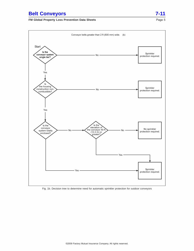
Fig. 1b. Decision tree to determine need for automatic sprinkler protection for outdoor conveyors
Belt Conveyors 7-11FM Global Property Loss Prevention Data Sheets Page 5
©2009 Factory Mutual Insurance Company. All rights reserved.
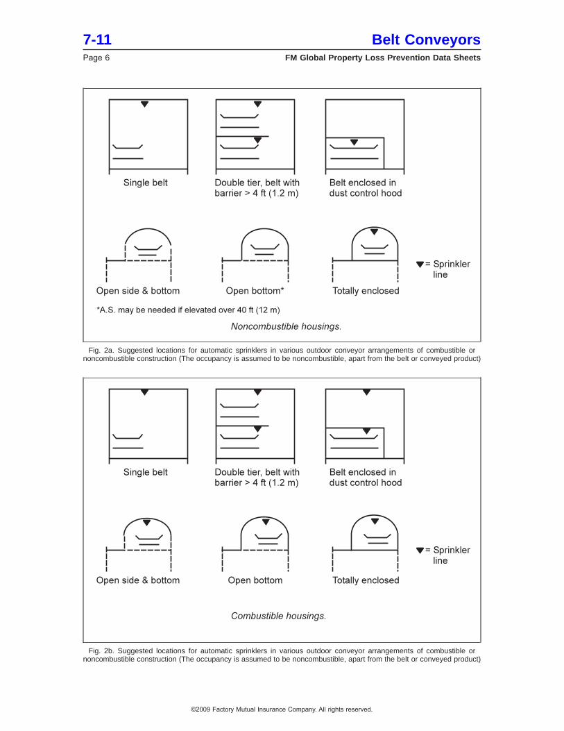
Fig. 2a. Suggested locations for automatic sprinklers in various outdoor conveyor arrangements of combustible ornoncombustible construction (The occupancy is assumed to be noncombustible, apart from the belt or conveyed product)
Fig. 2b. Suggested locations for automatic sprinklers in various outdoor conveyor arrangements of combustible ornoncombustible construction (The occupancy is assumed to be noncombustible, apart from the belt or conveyed product)
7-11 Belt ConveyorsPage 6 FM Global Property Loss Prevention Data Sheets
©2009 Factory Mutual Insurance Company. All rights reserved.
2.3.3.5 Protect outdoor captive conveyor systems as follows:
2.3.3.5.1 Provide automatic sprinklers throughout all floors of intermediate transfer, splice, or junctionbuildings of combustible construction, when sprinklers are also needed for the connecting conveyors.
2.3.3.5.2 Install sprinklers under barriers where solid barriers are more than 4 ft (1.2 m) wide.
2.3.3.5.3 Separate multiple tiers of conveyors when automatic sprinklers are needed per Figure 1.
2.3.3.5.4 Provide sprinkler protection where dust-tight enclosures are used to prevent or minimize dustliberation from belt conveyors; provide sprinklers inside the enclosures per Figure 2. Provide sprinklers atthe ceiling of the tunnel, gallery, or building housing the enclosed conveyor only if construction is combustible,or if other combustibles, such as grouped electrical cables, are present.
2.3.3.5.5 Where space inside the enclosures is limited, arrange piping on the exterior, and extend sprinklersthrough sealed openings. Provide inspection and maintenance hatches for each sprinkler.
2.3.3.5.6 Base sprinkler design for horizontal conveyors and inclined conveyors with a pitch of less than10° on the operation of the 10 most hydraulically remote sprinklers.
2.3.3.5.7 Base sprinkler design for inclined conveyors with a pitch of 10° or greater on the operation of the15 most hydraulically remote sprinklers.
2.3.3.5.8 Ensure a minimum end sprinkler pressure of 14 psi (0.96 bar). Limit sprinkler spacing on lines to12 ft (3.7 m). Use FMApproved sprinklers with a K factor of 8.0 (115) and a temperature rating of 165°F (74°C).
2.3.3.5.9 Where two or more parallel rows of sprinklers are provided over parallel conveyor belts in widegalleries, design the sprinklers to provide a density of 0.25 gpm/ft2 (10 mm/min) over 2000 ft2 (186 m2).
2.3.3.5.10 Protect sprinklers, piping, and detectors against impact damage from oversized pieces of conveyedmaterial.
2.3.3.5.11 To prevent collapse of a gallery due to water weight from sprinkler discharge, provide adequatedrainage via floor openings or by conveyor pitch.
2.3.3.5.12 Ensure there is sufficient water supply to accommodate 250 gpm (950 L/min) hose streams.
2.3.3.6 Provide the following protection for cross-country (overland) conveyors systems:
2.3.3.6.1 For totally enclosed systems, provide automatic sprinklers per Figure 1 and Section 2.3.3.5 above.An alternative would be to partially or completely remove the enclosure and protect as outlined below foropen or partially open conveyor systems.
2.3.3.6.2 For open or partially open conveyor systems, protect as follows:
a) Provide and maintain fire access roads that run parallel to the conveyor system and maintain a mobilewater tank with a pump and hose attached. Ensure the tank has a minimum capacity of 7500 gal(28,400 L). This will provide approximately one hour supply for manual firefighting response. Alternatively,provide standard fire hydrants at approximately 350 to 500 ft (91 to 152 m) intervals along the system.
b) Provide FM Approved heat or products of combustion detection devices inside transfer, splice, or drivehouses. Arrange detectors to sound an alarm and stop the conveyor belt.
c) Replace combustible weather hoods and intermediate buildings with noncombustible or fire-resistivealternatives.
2.3.3.6.3 Interlock the belt to shut down on sprinkler water flow or heat detector signal.
2.3.3.6.4 Base water supplies on a duration of one hour, and include 250 gal/min (950 L/min) for hose streams.
2.3.4 Specialty Conveyors
2.3.4.1 Protect Vertical Bucket Elevators as follows:
A. Provide automatic sprinkler protection at the top of the vertical bucket elevator shaft where the enclosureis noncombustible. If the enclosure is constructed from combustible materials, provide additional automaticsprinkler protection along the shaft (i.e., treat it as a vertical shaft with combustible sides).
Belt Conveyors 7-11FM Global Property Loss Prevention Data Sheets Page 7
©2009 Factory Mutual Insurance Company. All rights reserved.
B. Design the automatic sprinklers to deliver a minimum end sprinkler pressure of 14 psi (0.96 bar), usinga sprinklers with a K factor of 8.0 (115) or greater.
C. Refer to Data Sheet 7-75, Grain Storage and Milling and Data Sheet 7-76, Prevention and Mitigationof Combustible Dust Explosions and Fires if the bucket elevator transports grain or other combustibleproducts that may present an explosion hazard.
2.3.4.2 Protect Serpentine (pipe) conveyors systems with automatic sprinkler protection as outlined in section2.3.3.6.
2.3.4.3 Protect air-supported conveyor systems as follows:
2.3.4.3.1 Provide an interlock to stop the belt in the event of losing one or more compressors.
2.3.4.3.2 Provide automatic sprinkler protection for air-supported conveyors per Section 2.3.3.6 wherepractical.
2.3.4.3.3 Do not install grouped electrical cables, gas piping, or similar combustibles within the conveyorframework.
2.3.5 Explosion Protection
2.3.5.1 Design conveyor transfer points to minimize generation of dust. Most dust generated during conveyoroperations occurs when material is being transferred from one belt to another. Provide the following at theselocations:
A. A hood discharge chute designed so the material transferred does not impinge directly against theside of the chute.
B. A spoon loading chute so material is discharged onto the lower belt in the same direction and at thesame speed as the belt.
C. A settling enclosure with a passive dust-control system over the lower belt.
2.3.5.2 Tightly enclose conveyors handling combustible dust and / or provide collection systems to exhaustdust fines where conveyor transfer points are not properly designed.
2.3.5.3 Avoid the use of sub-grade tunnels for combustible dusts that present an explosion hazard.
2.3.5.4 Use damage-limiting construction for conveyor galleries, buildings, or enclosures handling combustibledusts per Data Sheet 1-44, Damage-Limiting Construction.
2.3.5.5 Refer to Data Sheet 7-76, Prevention and Mitigation of Combustible Dust Explosions and Fires, forrecommendation on the arrangement of explosion protection for combustible dusts.
2.3.6 Manual Protection
2.3.6.1 Provide (in easily accessible locations) either of the following manual protection options for indoorconveyors:
A. Small water hose stations with combination nozzles (solid stream and spray) for mop-up operationsafter a fire. This is the preferred option for manual protection.
B. Portable fire extinguishers rated for the occupancy in accordance with Data Sheet 4-5, PortableExtinguishers, located within 50 ft (15.2 m) of the conveyor. For conveyors on mezzanines, provideextinguishers at readily accessible locations on the mezzanine level.
2.3.6.2 Provide standard yard hydrant protection for outdoor conveyor systems captive to a plant site.
2.3.6.3. Provide FM Approved 1.5 in. (38 mm) hose stations for outdoor cross country conveyor systems.Locate the hose stations at suitable intervals inside totally or partially enclosed housings where size permitspersonnel access. Small hose connections can be made to wet-system sprinkler piping as long as the hosedemand is added at the point of connection. Where freezing is a concern, feed hose stations from dedicateddry-pipe valves or from normally shut, drained systems.
7-11 Belt ConveyorsPage 8 FM Global Property Loss Prevention Data Sheets
©2009 Factory Mutual Insurance Company. All rights reserved.
2.4 Utilities
2.4.1 Do not use conveying systems to transport utilities such as grouped electric cables, flammable gases,and ignitable liquids. If unavoidable, protect cables as recommended in Data Sheet 5-31, Cables and BusBars. Provide shutoffs for gases and liquids at locations external to the conveyor.
2.5 Operation and Maintenance
2.5.1 Where a history of longitudinal belt ripping exists, provide anti-rip detection devices to shut off drivepower and minimize further damage. An alternative is to use high tear-resistant belts.
2.5.2. Provide sufficient spare belting, drives, rollers, etc. to repair the longest belt at the plant, or ensurespares can be delivered within 24 hours from an offsite location.
2.5.3 Provide belt alignment interlocks for all styles of conveyor belt (e.g., horizontal conveyors, vertical bucketconveyors) to shut down the conveyor if the belt misaligns.
2.5.4 Maintain all bearings per manufacturer’s recommendations and keep them free of dust, product, andbuildup of lubrication material.
2.5.5 Have regular thermographic scans conducted on known or frequent ignition zones, such as conveyordrive pulleys and drums, to identify potential problems.
2.5.6 Clear weeds, brush, and trees from underneath and at least 25 ft (7.6 m) from both sides of the conveyorsystem. Remove combustible yard storage and limit the proximity of unprotected combustible buildings.Remove and relocate ignitable liquid operations, such as storage tanks, pumping stations, and tank truckunloading or loading facilities, from under or near conveyor systems.
2.5.7. Prevent fueled vehicles from being staged or parked under conveyor systems.
2.5.8. Develop preventive maintenance programs to reduce the potential of other common ignition sources,such as friction, overheated bearings or drive machinery, misalignment of belts or drivers, etc.
2.5.9. Ensure all variable speed drive motors are operated within the frequency range recommended by themanufacturer.
2.6 Ignition Source Control
2.6.1 Provide interlocks to shut down the feed system where heated materials are discharged onto belts ifthe material exceeds a safe temperature or if the belt or cooling system shuts down.
2.6.2 Provide motion-sensing switches or other devices to detect a slipping or jammed conveyor. Interlockthe motion sensors to shut off drive power when the belt stops or slows down more than 20% of normal speed.Interlock contributing conveyors so no operating conveyor can discharge material to a stopped downstreamconveyor.
2.6.3 Use the FM Global Hot Work Permit System for all hot work activities near the conveyors. Refer to10-3, Hot Work Management, for further details.
2.6.4 Prohibit smoking around all combustible conveyor belts or conveyor belts that transport combustiblematerials.
2.6.5 Protect and arrange gas-fired space heaters in conveyor systems as recommended in Data Sheet 6-20,Space Heaters.
2.6.6 Interlock drive motors to shut down on detection of overload, over current condition, or if the belt slowsdown more than 20%.
2.6.7 Arrange electrical equipment in conveyor systems handling combustible dusts as recommended inData Sheet 5-1, Electrical Equipment in Hazardous Locations, or appropriate jurisdictional electrical codesfor hazardous locations.
2.6.8 Install magnetic tramp metal separators at rail car and truck dump hoppers and on conveyors aheadof grinding or pulverizing operations when the material being conveyed is combustible.
Belt Conveyors 7-11FM Global Property Loss Prevention Data Sheets Page 9
©2009 Factory Mutual Insurance Company. All rights reserved.
3.0 SUPPORT FOR RECOMMENDATIONS
3.1 Belt Flammability
3.1.1 General
Although the conveyed product and the structure may be noncombustible, loss history demonstrates thatthe belt itself presents sufficient combustible loading to spread the fire without other fuel contribution.
Conveyor belts are manufactured of natural and synthetic rubber or plastic, such as polyvinyl chloride (PVC),acetal, polyethylene, polypropylene and nylon. They are often reinforced with fibers for strength. Outdoorbelts usually are formed in laminated layers and may have, for example, a PVC base for flexibility with a rubbertop layer to allow for product adhesion under incline conditions.
Belt conveyors, whether made of natural or synthetic rubber or plastics, generally are assumed to be capableof self-sustained fire propagation whether or not other combustibles are present. For this reason, automaticsprinkler protection has been recommended for most installations regardless of the conveyor material’sclaimed fire or flame retardancy, or of the combustibility of materials conveyed. The use of fire-retardant beltsis encouraged. They are typically harder to ignite when exposed to a low-energy ignition source, therebyreducing the frequency of fire.
3.1.2 Laboratory-Scale Testing
The following is a comparison between a non-fire-retardant belt and a belt advertised as a flame-retardantconveyor belt.
Heat of combustion: The heat of combustion of both belts was determined by oxygen bomb calorimetry.The non-fire-retardant belt was 9,720 Btu/lb The fire-retardant belt was 9,755 Btu/lb
Parallel Panel Test: Tests were conducted with two vertically mounted 6 in. by 18 in. (152 x 457 mm) panelsof each material, spaced 1⁄2 in. (13 mm) apart. Both conveyor belts were exposed by a Bunsen Burner flamebetween the panels at the bottom.
• Standard belt: Ignition occurred in 5 s with flames reaching the tops of the panels in 55 seconds. Afterabout 65 seconds, the sample was noted to begin melting and dripping. The burner flame was removedafter 2 minutes. Flame continued to propagate. The sample melted and dripped into a large liquid pool fire.
• Flame retardant belt: Ignition occurred in 5 seconds with flames reaching the tops of the panels in 75seconds. The burner flame was removed after about 2 minutes and flaming extinguished with no meltingor dripping of the material noted. A propane torch was then applied to the belt for periods of 33 and 30seconds. Melting, dripping, and deformation did occur, especially during the second attempt, but afterremoval of the torch after each attempt, the flaming extinguished. After the third application of the torch for20 seconds, the flaming continued, slowly propagating up the sample. The sample melted and drippedinto a liquid pool as observed with the “standard” conveyor belt.
Fire Propagation Index (FPI) Test: A test of a non-fire-retardant belt resulted in an FPI of 14.9. The testfor the flame retardant belt resulted in an FPI of 11.4.
The fire propagation index (FPI) used to classify electric cables has also been successfully used to classifyconveyor belting. During conveyor belt tests using the FM Approvals 500 kW small-scale flammabilityapparatus, excellent agreement was found between the small-scale FM Approvals’ tests and tests conductedby the US Bureau of Mines (USBM) large-scale fire gallery in the 1980s. Based on the results of this study,conveyor belt samples were able to be classified as propagating or non-propagating.
The propagating conveyor belts have been classified as those that develop an FPI higher than 7 on theflammability apparatus and for which flame propagates rapidly followed by entire sample destruction in MSHAlarge-scale fire gallery tests. The non-propagating types are those for which the FPI is 7 or less, and forwhich flame did not propagate beyond the ignition region in MSHA large-scale fire gallery tests.
3.2 Major Factors Affecting the Need for Fire Protection
Major factors influencing the need for special fire protection for conveyors are as follows:
7-11 Belt ConveyorsPage 10 FM Global Property Loss Prevention Data Sheets
©2009 Factory Mutual Insurance Company. All rights reserved.
• The belt itself provides sufficient combustible loading to spread a fire. Major fires have spread on beltsas narrow as 2 ft (0.6 m) wide and on systems carrying noncombustible materials such as limestone, ironore, and metal cans.
• While not as common as single-tier systems, multiple-tier arrangements represent greater verticalcombustible loading as well as a more favorable burning configuration than single-tier systems. A tier isdefined as the feed and return layers of the belt. A single-tier system has two horizontal layers of beltingstacked vertically; a two-tier system has four horizontal layers of belting stacked vertically.
• Conveyor belts emit dense, black, toxic smoke when ignited. This feature can severely hamper manualfirefighting in underground or totally enclosed systems where entry and means of heat venting are limited.
• Ventilation (air flow) within a sprinklered tunnel or gallery does not appear to influence fire spread to a greatdegree. FM Global conducted air-flow studies over conveyors in coal mines to test detector sensitivity.These tests were correlated to sprinkler operation after detection by computer simulation.
• Fire Service response may be delayed, as many conveyors are in unoccupied areas. Fires occurring withoutautomatic fire protection can be expected to be well developed before they are detected and the fire serviceresponds.
• Accessibility and openness of the system directly influence fire spread, severity, ease of manual response,and damage. A fully enclosed system will not allow heat to be released or hose streams to be introducedfrom outside the conveyor system. Firefighters cannot physically fight the fire except from the ends of theconveyor, and often, dense smoke prevents effective response. A firefighting team will rarely enter anenclosed conveyor system. All of these factors combine to permit a free-burn fire that will spread rapidlywith very high heat release and expose the steel structure. If this occurs, the entire structure can sag,cantilever, or collapse. Alternatively, an open or partially open system will allow heat to escape and hosestreams to penetrate the fire plume. Damage can be significantly less, with structural collapse much lesslikely.
• Height of the conveyor above grade influences accessibility; incline influences the rate of fire spread.Generally, galleries or towers greater than 40 ft (12.2 m) above grade should be considered inaccessiblefor manual firefighting, even with substantial openings for hose stream penetration. Inclines of more than10% allow for a faster spreading flame front.
• Unprotected interior exposed steel or combustible support framing on an elevated, totally enclosed structurecan lead to collapse of the entire elevated portion during a fire.
• Intermediate buildings, such as transfer, splice, and tensioner houses, assume the same hazard as tunnelsor elevated galleries of similar construction and accessibility. The presence of motorized drive equipmentand more frequent personnel activities in these buildings creates more frequent ignition sources.
An explosion hazard may also exist in a conveyor system used to handle materials that can generatecombustible dusts (e.g., sulfur, coal, various grains). A small initial dust explosion can initiate secondary dustexplosions that can propagate the entire length of tunnels or galleries. Fires originating at conveyor beltshave been the ignition source for dust explosions in the grain industry and coal mining facilities.
Other exposures to conveyors include impact damage from mobile equipment, collapse, and longitudinalripping from sharp objects. Belts that have become separated have been known to slide down elevatedgalleries or tunnels, causing impact damage and presenting a challenge to cleanup operations.
4.0 REFERENCES
4.1 FM Global
Data Sheet 1-23, Protection of Openings in Fire SubdivisionsData Sheet 1-44, Damage-Limiting ConstructionData Sheet 1-54, Roof Loads for New ConstructionData Sheet 1-57, Plastics in ConstructionData Sheet 4-1N, Fixed Water Spray Systems for Fire ProtectionData Sheet 4-5, Portable ExtinguishersData Sheet 5-1, Electrical Equipment in Hazardous LocationsData Sheet 5-31, Cables and Bus BarsData Sheet 6-20, Space Heaters
Belt Conveyors 7-11FM Global Property Loss Prevention Data Sheets Page 11
©2009 Factory Mutual Insurance Company. All rights reserved.
Data Sheet 7-12, Mining and Ore ProcessingData Sheet 7-75, Grain Storage and MillingData Sheet 10-3, Hot Work ManagementData Sheet 7-75, Grain Storage and MillingData Sheet 7-76, Prevention and Mitigation of Combustible Dust Explosions and Fires
4.2 Other
ASTM International. Standard Test Methods for Measurements of Synthetic Polymer Material FlammabilityUsing a Fire Propagation Apparatus (FPA). ASTM E2058.
APPENDIX A GLOSSARY OF TERMS
FM Approved: References to ‘‘FM Approved’’ in this data sheet mean the product or service has satisfiedthe criteria for FM Approval. Refer to the Approval Guide for a complete listing of products and services thatare FM Approved.
Ignitable Liquid: Any liquid or liquid mixture that is capable of fueling a fire, including flammable liquids,combustible liquids, inflammable liquids, or any other reference to a liquid that will burn. An ignitable liquidmust have a fire point.
APPENDIX B DOCUMENT REVISION HISTORY
January 2012. Terminology related to ignitable liquids has been revised to provide increased clarity andconsistency with regard to FM Global’s loss prevention recommendations for ignitable liquid hazards.
October 2009. The following changes were made:
1. Added protection recommendations for indoor conveyor belts in manufacturing and warehouse settings.
2. Added protection requirements for serpentine (also called pipe) conveyors and air-supported conveyors.
3. Removed requirements for underground mines; these are covered in Data Sheet 7-12, Mining and OreProcessing.
4. Added protection recommendations for vertical bucket elevators.
January 2005. Clarification of protection needed for single conveyor systems, where barriers are locatedbetween supply and return belts, was made (section 2.3.1.1).
September 2004. Minor editorial changes were done for this version.
Clarification was made in section 3.2, Conveyor Belt Flammability.
January 2003. Minor editorial changes were done for this version.
January 2000. This revision of the document was reorganized to provide a consistent format.
7-11 Belt ConveyorsPage 12 FM Global Property Loss Prevention Data Sheets
©2009 Factory Mutual Insurance Company. All rights reserved.
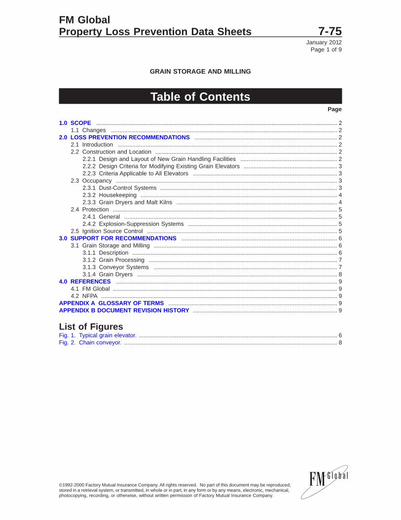
January 2012Page 1 of 9
GRAIN STORAGE AND MILLING
Table of ContentsPage
1.0 SCOPE ................................................................................................................................................... 21.1 Changes .......................................................................................................................................... 2
2.0 LOSS PREVENTION RECOMMENDATIONS ....................................................................................... 22.1 Introduction ...................................................................................................................................... 22.2 Construction and Location ............................................................................................................... 2
2.2.1 Design and Layout of New Grain Handling Facilities ........................................................... 22.2.2 Design Criteria for Modifying Existing Grain Elevators ......................................................... 32.2.3 Criteria Applicable to All Elevators ........................................................................................ 3
2.3 Occupancy ....................................................................................................................................... 32.3.1 Dust-Control Systems ............................................................................................................ 32.3.2 Housekeeping ........................................................................................................................ 42.3.3 Grain Dryers and Malt Kilns .................................................................................................. 4
2.4 Protection ......................................................................................................................................... 52.4.1 General .................................................................................................................................. 52.4.2 Explosion-Suppression Systems ........................................................................................... 5
2.5 Ignition Source Control .................................................................................................................... 53.0 SUPPORT FOR RECOMMENDATIONS ............................................................................................... 6
3.1 Grain Storage and Milling ................................................................................................................ 63.1.1 Description ............................................................................................................................. 63.1.2 Grain Processing ................................................................................................................... 73.1.3 Conveyor Systems ................................................................................................................ 73.1.4 Grain Dryers .......................................................................................................................... 8
4.0 REFERENCES ....................................................................................................................................... 94.1 FM Global ......................................................................................................................................... 94.2 NFPA ................................................................................................................................................ 9
APPENDIX A GLOSSARY OF TERMS ....................................................................................................... 9APPENDIX B DOCUMENT REVISION HISTORY ........................................................................................ 9
List of FiguresFig. 1. Typical grain elevator. ......................................................................................................................... 6Fig. 2. Chain conveyor. .................................................................................................................................. 8
FM GlobalProperty Loss Prevention Data Sheets 7-75
©1992-2000 Factory Mutual Insurance Company. All rights reserved. No part of this document may be reproduced,stored in a retrieval system, or transmitted, in whole or in part, in any form or by any means, electronic, mechanical,photocopying, recording, or otherwise, without written permission of Factory Mutual Insurance Company.
1.0 SCOPE
This data sheet applies to the handling or storage of grains such as wheat, corn, oats, barley, rice, soybeans,cocoa beans, and flaxseed. In addition, it covers the mechanical processing of these grains to products usedfor human consumption, such as flour, and to animal feeds. It does not cover wood chip storage (see DataSheet 8-27, Storage of Wood Chips), cottonseed storage, or solvent extraction of oils.
1.1 Changes
January 2012. Terminology related to ignitable liquids has been revised to provide increased clarity andconsistency with regard to FM Global’s loss prevention recommendations for ignitable liquid hazards.
2.0 LOSS PREVENTION RECOMMENDATIONS
2.1 Introduction
The safeguards recommended below apply to new and existing elevators. When modifications are made toexisting elevators, the recommendations pertaining to new elevators should be implemented, insofar aspractical.
2.2 Construction and Location
2.2.1 Design and Layout of New Grain Handling Facilities
2.2.1.1 All new grain handling facilities should be arranged as follows:
1. The workhouse area where grain is cleaned and weighed should be separate from storage silos or tanks,or any milling, loading/unloading, or processing plants. Provide separation to minimize propagation ofexplosion between areas.
2. Conveyors connecting the workhouse to loading or unloading facilities and storage silos or tanks shouldrun above ground immediately after leaving subgrade structures. Tunnels should not be used.
3. Elevating conveyors should be located outside the workhouse, preferably as part of a separate structure.Inclined conveyors are preferred over vertical bucket elevators.
2.2.1.2 All construction should be steel or reinforced concrete frame with explosion-relieving panels designedto relieve at a pressure not more than 30 lb/ft2 (1.4 kPa) unless windstorm resistance requirements are higher(See Data Sheet 1-28, Wind Design, and Data Sheet 1-44, Damage Limiting Construction). Protect bucketelevators in accordance with Data Sheet 7-76, Prevention and Mitigation of Combustible Dust Explosions andFires. For rooms and buildings, contact FM Global Research for assistance in determining the requiredamount of explosion venting area and explosion resisting wall strength.
2.2.1.3 Storage silos may be constructed of concrete or other noncombustible material. The design of silosshould include the following:
1. Construct the foundation in such a way that the retrieval conveyor beneath the bins is above grade andvented as much as possible. The design should allow for the installation of explosion-relieving panels onboth sides for the entire length of the conveyor. The vents should be designed to relieve at 30 lb/ft2 (1.4 kPa)or less unless windstorm resistance requirements are higher (Data Sheet 1-28).
2. Conveyors over the top of the silos should preferably not be contained within a separate enclosure gallery.Where galleries are used, explosion-relieving panels designed to relieve at not more than 30 lb/ft2 (1.4 kPa)should be provided along the entire length of the gallery. Contact FM Global for assistance in determiningthe required amount of explosion venting area and explosion resisting wall strength.
3. Vents for relieving dust-laden air should be designed to discharge directly to the outside. Do not ventone bin into another or into a conveyor enclosure. Dust collection systems from different silo groups or tankgroups should not be manifolded together.
2.2.1.4 Interior wall and ceiling surfaces in the workhouse and in bins above the maximum grain level shouldhave a smooth, high-gloss finish to facilitate cleaning, and a minimum of horizontal surfaces to limit dustaccumulations.
7-75 Grain Storage and MillingPage 2 FM Global Property Loss Prevention Data Sheets
©1992-2000 Factory Mutual Insurance Company. All rights reserved.
2.2.2 Design Criteria for Modifying Existing Grain Elevators
Recommendations 2.2.1.1 through 2.2.1.4 involve major capital expenses. In most cases, it would be practicalonly when major remodeling of the facility is done. If a facility is adding storage capacity, it may be practicalto relocate existing conveyors and loading or unloading facilities, incorporating damage limited construction.If new grain handling equipment is being installed, it may be possible to reconstruct the workhouse andrelocate the elevator legs as recommended for adequate venting.
2.2.2.1 Replace concrete workhouse construction with damage-limiting construction. Design all walls torelieve at 30 lb/ft2 (1.4 kPa) or less unless windstorm resistance requirements are higher (Data Sheet 1-28).Contact FM Global Research for assistance in determining the required amount of explosion venting areaand explosion resisting wall strength. Bins in or beneath workhouses should have at least one outside wall.
2.2.2.2 Eliminate reinforced concrete conveyor galleries running over silo groups. If necessary, replace withenclosures of damage-limiting construction. The panels should be designed to relieve at not more than30 lb/ft2 (1.4 kPa) unless windstorm resistance requirements are higher (Data Sheet 1-28). Contact FM GlobalResearch for assistance in determining the required amount of explosion venting area and explosion resistingwall strength.
2.2.2.3 Eliminate all below-grade conveyor tunnels where explosion venting does not exist. (This does notapply to ‘‘tunnels’’ beneath silos.) Use above-grade conveyors where possible. If roadways or railway tracksdo not permit above-grade conveyors, below-grade tunnels are acceptable if conveyors are totally enclosed(see Criteria Applicable to All Elevators). Enclosed belt conveyors should have provision for cleaning theconveyor enclosure.
2.2.2.4 Replace interior elevator legs with exterior elevators, preferably using inclined belt conveyors. Protectbucket elevators in accordance with Data Sheet 7-76.
2.2.3 Criteria Applicable to All Elevators
No other safeguards are more important in the prevention of dust explosions than the design of properdust-control equipment, and a regular program of good housekeeping practices.
2.3 Occupancy
2.3.1 Dust-Control Systems
2.3.1.1 All indoor grain handling equipment should be aspirated or totally enclosed, and operate at a negativepressure relative to the environment, to minimize release of dust into the elevator structure. Enclosed beltconveyors should have facilities for cleaning the interior of the enclosure.
2.3.1.2 Collected dust should not be reintroduced to the grain stream within the elevator or workhouse areaif the grain is going into storage. Dust may be returned to the grain stream after it leaves the elevator suchas at ship, car, or truck loading facilities.
2.3.1.3 Size the dust collection system to the maximum anticipated grain flow. Airflows should be sufficientto prevent dust from accumulating within equipment or ducts. A major reason for dust control problems hasbeen dust collection systems of inadequate capacity to handle increased grain flows with the associatedincrease in dust generation.
2.3.1.4 Provide intakes at all points where dust is liberated, including unloading dumps, conveyor transferpoints, and elevator legs and heads; at sifting, cleaning, dehulling, and screening equipment; at bin-filling anddischarge points; and at milling and bagging processes. Individual collecting systems should be providedfor each building area, to the extent possible, to limit the propagation of dust explosions through the collectionsystem to large areas of the plant.
2.3.1.5 All air circulatory vents interconnecting bins should be sealed and bins arranged to vent to theoutdoors.
2.3.1.6 Turnheads should have a rotating annular sleeve that seals spouts not in use. Turnheads shouldbe pressurized to minimize dust buildup within the equipment when bins are being filled.
2.3.1.7 Interlocks should be provided to prevent operation of dust-producing processes when the collectionsystem is not operating. Delays sufficient to empty belts and buckets may be incorporated with processshutdown.
Grain Storage and Milling 7-75FM Global Property Loss Prevention Data Sheets Page 3
©1992-2000 Factory Mutual Insurance Company. All rights reserved.
2.3.1.8 Dust collectors should be designed and protected in accordance with Data Sheet 7-73, DustCollectors and Collection Systems and Data Sheet 7-76. Dust collectors should be located outdoors. If thisis not possible, they should be located in a room free of dust deposits likely to be dispersed by an explosion.Indoor collectors should be located at an outside wall and vented through the wall in accordance with DataSheet 7-76.
2.3.1.9 Dust collection systems taking suction from equipment with a history of explosions should beequipped with an explosion suppression system. Such dust collection systems should not be manifolded withother, more extensive systems.
2.3.1.10 Elevator, conveyor, and processing equipment exteriors and interiors should be accessible forinspection and maintenance.
2.3.2 Housekeeping
2.3.2.1 The highest order of housekeeping should be maintained to prevent accumulation of combustibledusts. Even with well designed dust-tight equipment, small quantities may escape and present a serioushazard unless removed at frequent intervals. Dust accumulations should be removed by a combination of:
1. Vacuum cleaning. Central vacuum cleaning systems may be used. These systems may operate from theelevator’s dust control system.
2. Soft push brooms. Soft push brooms tend to minimize dust clouds when sweeping. Pneumatic collectoropenings near floor level may be used to pick up sweepings. Clearance should be provided beneath andaround equipment as necessary to permit sweeping or vacuum cleaning.
2.3.2.2 Restricted blow down cleaning with compressed air may be used for inaccessible areas if the followingprocedure is strictly adhered to:
1. A permit system similar to the welding permit system should be used.
2. Clean as much dust with vacuum and soft broom as is possible to remove in accessible areas.
3. Shut down power to equipment in the area.
4. Blow down inaccessible dusts.
5. Clean up blow down with vacuum or soft broom.
2.3.2.3 Special attention to prompt housekeeping should be given to below-grade areas where explosionventing is not possible, and to areas in which dust clouds may be more frequent. This includes receivingtunnels near car and truck unloading, near openings for filling silos and bins, and adjacent to bucket elevators.
2.3.3 Grain Dryers and Malt Kilns
2.3.3.1 Dryers, including furnace rooms, should be of noncombustible construction and separated from silosand bins. Steam coils should be arranged and maintained to prevent dust accumulations on coils, fins, orheated surfaces. Cleaning equipment should be provided in train lines ahead of dryers to remove debris thatmight clog the dryer. Air intakes should be located in dust-free areas, and protected by coarse screens tokeep out debris.
2.3.3.2 Explosion vents should be provided in dryers depending on design, in accordance with Data Sheet6-9, Industrial Ovens and Dryers. Explosion vents are not needed in malting kilns.
2.3.3.3 Dryers should be equipped with automatic temperature control. In addition, an independent safetycontrol circuit should be provided. This system should be arranged to shut down the heating supply and fanswhen loading or unloading the dryer in the event of excessive temperature in the dryer, stoppage of the hotair or cooling air fans, or burner flame failure. The excess temperature limit control should be setapproximately 25°F (14°C) above the operating temperature of the dryer. In the event of a fire in a dryer orkiln, the fans should be shut off.
2.3.3.4 A means should be provided at the dryer discharge so that, if fire occurs in the dryer, stock can beintercepted and dumped. Grain should be thoroughly cooled before storing.
7-75 Grain Storage and MillingPage 4 FM Global Property Loss Prevention Data Sheets
©1992-2000 Factory Mutual Insurance Company. All rights reserved.

2.4 Protection
2.4.1 General
2.4.1.1 Automatic sprinklers should be installed in all grain storage and processing buildings whereconstruction or equipment is combustible. Sprinklers, though desirable, may be omitted in areas of fire-resistive or noncombustible construction, if the only combustible material present is the grain. Sprinklersshould be installed in interiors of large processing equipment, such as the lowest dry level of malting kilns,bag dust collectors, and elevator legs. In elevator legs, sprinklers are needed only at the top unless theenclosure is combustible, in which case it should be treated as a vertical shaft with combustible sides.
2.4.1.2 Sprinklers should be installed in accordance with Data Sheets 2-8, Earthquake Protection forWater-Based Fire Protection Systems and 2-0, Installation Guidelines for Automatic Sprinklers with watersupplies in accordance with Data Sheet 3-26, Fire Protection Water Demand for Nonstorage SprinkleredProperties. In unheated dusty areas, preaction systems are preferable to dry systems to minimize airdischarge which can stir up dust clouds.
2.4.1.3 In areas where combustible dusts are present, do not attach sprinkler piping to any wall, ceiling, orroof that is expected to be displaced by the pressure of a room or building explosion, and do not allow suchstructures to support sprinkler system piping.
2.4.1.4 Standpipes with hose connections should be provided at all operating levels in elevator houses,conveyor structures, and cleaning and drying areas in accordance with Data Sheet 4-4N, Standpipe and HoseSystems (NFPA). Equipment should include Approved 11⁄2 in. (38 mm) hose with combination spray nozzles,and connections for 21⁄2 in. (64 mm) hose. Some of these areas will be unheated, requiring a dry standpipewith each hose station equipped with a remote control operating device.
2.4.2 Explosion-Suppression Systems
2.4.2.1 Explosion-suppression systems should be installed to protect the entire volume of the followingenclosures:
1. Throughout all indoor elevator legs. The suppression system should be extended throughout allinterconnecting enclosed equipment including head and boot pulley enclosures, conveyors, garners, andscale hoppers unless the equipment is arranged for choked feeds by use of star valves, screw conveyorswith flights removed, or drag conveyors.
2. Throughout all indoor dust handling equipment including cyclones, bag collectors, and associated ductingfor dust-laden air that cannot be adequately and directly vented to the outdoors.
3. Throughout all dust and product handling systems that are on the discharge end of equipment that hasa history of explosions.
2.4.2.2 Where explosion venting can be provided, explosion-suppression blocking systems minimize thechances of an explosion propagating from one area to another. Blocking systems should be installed in theboot, the infeed, and the discharge and head pulley areas of all bucket elevators.
2.5 Ignition Source Control
2.5.1 Electrical equipment in grain handling areas should be suitable for Class II, Division 1 or 2, inaccordance with Data Sheet 5-1, Electrical Equipment in Hazardous (Classified) Locations.
2.5.2 Bearings for conveyor bucket elevator terminal pulleys should be press — or shrink — fitted withtapered adapter sleeves. Slip-fit bearings secured with set screws should not be used. Bearings should belocated outside of machinery enclosures where overheated bearings will be less exposed to dust cloudsand where they will be more accessible for inspection and service.
2.5.3 Magnetic separators should be installed at car and truck dump hoppers or conveyors, and on conveyorsahead of milling or grinding operations, to remove tramp metal.
2.5.4 Space heating equipment should not have open flames or any exposed surface at temperatures above340°F (171°C).
2.5.5 Belt alignment limited switches should be provided on conveyors and bucket elevators to shut downthose belts that are improperly tracking. A motion-sensing switch also should be provided on a driven pulley
Grain Storage and Milling 7-75FM Global Property Loss Prevention Data Sheets Page 5
©1992-2000 Factory Mutual Insurance Company. All rights reserved.
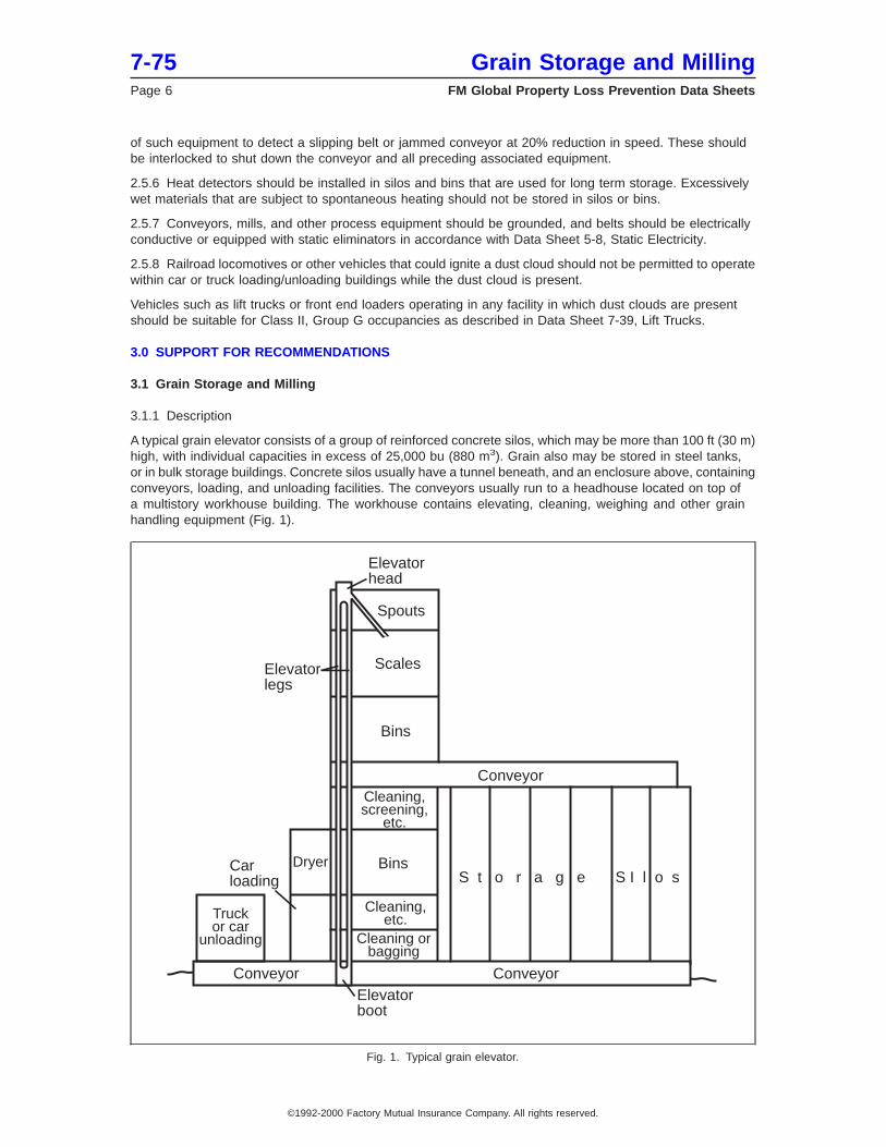
of such equipment to detect a slipping belt or jammed conveyor at 20% reduction in speed. These shouldbe interlocked to shut down the conveyor and all preceding associated equipment.
2.5.6 Heat detectors should be installed in silos and bins that are used for long term storage. Excessivelywet materials that are subject to spontaneous heating should not be stored in silos or bins.
2.5.7 Conveyors, mills, and other process equipment should be grounded, and belts should be electricallyconductive or equipped with static eliminators in accordance with Data Sheet 5-8, Static Electricity.
2.5.8 Railroad locomotives or other vehicles that could ignite a dust cloud should not be permitted to operatewithin car or truck loading/unloading buildings while the dust cloud is present.
Vehicles such as lift trucks or front end loaders operating in any facility in which dust clouds are presentshould be suitable for Class II, Group G occupancies as described in Data Sheet 7-39, Lift Trucks.
3.0 SUPPORT FOR RECOMMENDATIONS
3.1 Grain Storage and Milling
3.1.1 Description
A typical grain elevator consists of a group of reinforced concrete silos, which may be more than 100 ft (30 m)high, with individual capacities in excess of 25,000 bu (880 m3). Grain also may be stored in steel tanks,or in bulk storage buildings. Concrete silos usually have a tunnel beneath, and an enclosure above, containingconveyors, loading, and unloading facilities. The conveyors usually run to a headhouse located on top ofa multistory workhouse building. The workhouse contains elevating, cleaning, weighing and other grainhandling equipment (Fig. 1).
Elevatorhead
Elevatorlegs
Elevatorboot
Spouts
Scales
Bins
Bins
Conveyor
Conveyor
S t o r a g e S I l o s
Conveyor
Carloading
Cleaning,screening,
etc.
Cleaning,etc.
Cleaning orbagging
Dryer
Truckor car
unloading
Fig. 1. Typical grain elevator.
7-75 Grain Storage and MillingPage 6 FM Global Property Loss Prevention Data Sheets
©1992-2000 Factory Mutual Insurance Company. All rights reserved.
Construction of this type has been common for grain elevators for years. Typically, explosion venting hasbeen inadequate. The chief efforts in loss prevention have been to control ignition sources to prevent primaryexplosions, and to maintain excellent housekeeping to prevent propagation and secondary explosions.
Some elevators of recent construction avoid the use of reinforced concrete workhouses. In such installations,conveyors may run above ground from loading/unloading areas to a separate workhouse. The workhouseis usually of steel frame and may be of damage-limiting construction. Conveyors run above ground from theworkhouse to separate banks of reinforced concrete storage silos or steel tanks.
While the control of ignition sources and housekeeping are still important, the damage limiting constructionwill limit the extent of the damage. Besides providing explosion venting in the workhouse, the use of aboveground conveyors and separation of the workhouse from the storage bins significantly reduces the probabilityof an explosion propagating throughout the facility in conveyor tunnels and galleries.
Both of the above types of elevators also incorporate facilities for loading and unloading railroad cars, trucks,barges, and ships.
3.1.2 Grain Processing
In most grain elevators, belt conveyors are used to transport grain from the unloading facilities to an incomingbin. From the bin, the grain is transported to elevating conveyors in the workhouse. The elevating conveyorslift the grain up to the headhouse, where it is stored in an upper bin. Grain is then cleaned and weighed.From the headhouse, the grain is transported by belt conveyor through the upper gallery to a silo storagebin or to storage tanks.
Retrieval of the grain is accomplished by gravity feed from the storage bins onto belt conveyors usually locatedin below-grade tunnels. The grain is again transported by elevating conveyors to the headhouse where itis weighed and transferred by gravity through spouts to shipping bins. The shipping bins are normally locatedinside the workhouse. Often, these bins are interconnected by spouts. Grain sampling is done as it passesfrom the shipping bins to belt conveyors for transfer to ships, barges, rail cars, etc.
In flour or feed milling, grain passes through various kinds of mills, followed by separators or blenders, moremills, etc., until the proper consistency and composition are achieved. The ground material usually isconveyed in closed equipment to bagging, bulk storage, or bulk loading areas, or to further processes suchas mash tubs or cookers.
3.1.3 Conveyor Systems
In a grain elevator, most of the conveying is done by belt conveyor. Bucket elevators generally are used inthe elevator legs. A bucket elevator consists of plastic or metal buckets attached to a moving vertical belt.In the typical installation, the belt moves in a metal conveyor enclosure, which is located inside a concreteshaft called an elevator leg. Electric-driven motors move the belt. At the top of the leg, the belt turns over andgrain spills from the bucket into the upper garner. The empty buckets then return to the ‘‘boot’’ of the legin an upside-down position. In the boot, they are turned over again and refilled with grain.
An operating advantage of the bucket elevator is the low power needed to lift the grain. A major disadvantageis the available volume for explosive dust and air mixtures to develop. This is especially true in the downleg, where residual dust from the upside-down buckets can filter through the entire leg. In addition, ignitionsources from overheated bearings in the head, knee or boot of the conveyor, or from cutting and welding,tramp metal, or falling buckets are often present. An explosion originating in an elevator leg, especially onelocated inside a concrete shaft in the workhouse, can rapidly develop extreme pressure and be communicatedthroughout the entire elevator.
Other conveyors can be used in place of the bucket elevator. Chain conveyors (Fig. 2) can be installed ina vertical, horizontal or inclined position. These conveyors consist of paddles or flights enclosed in a heavysteel, usually dust-tight, enclosure. The grain and flights form a solid mass as they move upward. Anadvantage of this type of conveyor is the grain-choked ‘‘up’’ leg. The down leg could accumulate dust, althoughbuildup is likely to be less than in a bucket elevator.
Conventional belt conveyors can be installed on an incline to replace vertical elevators. Although this typeof installation requires considerable space, it eliminates the need for any elevator legs within the workhouse.
Grain Storage and Milling 7-75FM Global Property Loss Prevention Data Sheets Page 7
©1992-2000 Factory Mutual Insurance Company. All rights reserved.
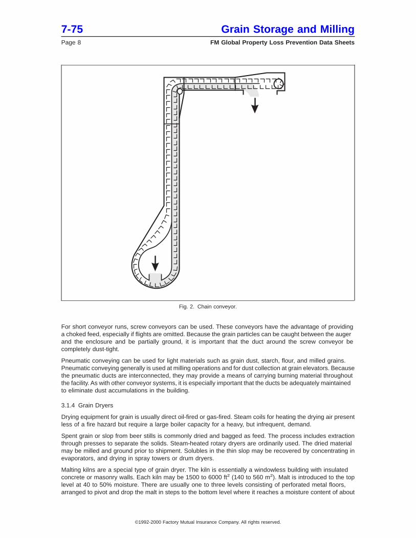
For short conveyor runs, screw conveyors can be used. These conveyors have the advantage of providinga choked feed, especially if flights are omitted. Because the grain particles can be caught between the augerand the enclosure and be partially ground, it is important that the duct around the screw conveyor becompletely dust-tight.
Pneumatic conveying can be used for light materials such as grain dust, starch, flour, and milled grains.Pneumatic conveying generally is used at milling operations and for dust collection at grain elevators. Becausethe pneumatic ducts are interconnected, they may provide a means of carrying burning material throughoutthe facility. As with other conveyor systems, it is especially important that the ducts be adequately maintainedto eliminate dust accumulations in the building.
3.1.4 Grain Dryers
Drying equipment for grain is usually direct oil-fired or gas-fired. Steam coils for heating the drying air presentless of a fire hazard but require a large boiler capacity for a heavy, but infrequent, demand.
Spent grain or slop from beer stills is commonly dried and bagged as feed. The process includes extractionthrough presses to separate the solids. Steam-heated rotary dryers are ordinarily used. The dried materialmay be milled and ground prior to shipment. Solubles in the thin slop may be recovered by concentrating inevaporators, and drying in spray towers or drum dryers.
Malting kilns are a special type of grain dryer. The kiln is essentially a windowless building with insulatedconcrete or masonry walls. Each kiln may be 1500 to 6000 ft2 (140 to 560 m2). Malt is introduced to the toplevel at 40 to 50% moisture. There are usually one to three levels consisting of perforated metal floors,arranged to pivot and drop the malt in steps to the bottom level where it reaches a moisture content of about
Fig. 2. Chain conveyor.
7-75 Grain Storage and MillingPage 8 FM Global Property Loss Prevention Data Sheets
©1992-2000 Factory Mutual Insurance Company. All rights reserved.
4%. In each level, the malt has a depth of one to two feet (300 to 600 mm). Heated air is brought in at thebottom at 190° to 240°F (88° to 116°C) and is exhausted from the top at 60° to 70°F (16° to 21°C).
4.0 REFERENCES
4.1 FM Global
Data Sheet 1-28, Wind DesignData Sheet 1-44, Damage Limiting ConstructionData Sheet 2-8, Earthquake Protection for Water Based Fire Protection SystemsData Sheet 2-0, Installation Guidelines for Automatic SprinklersData Sheet 3-26, Fire Protection Water Demand for Nonstorage Sprinklered PropertiesData Sheet 4-4N, Standpipe and Hose SystemsData Sheet 5-1, Electrical Equipment in Hazardous(Classified) LocationsData Sheet 5-8, Static ElectricityData Sheet 6-9, Industrial Ovens and DryersData Sheet 7-39, Lift TrucksData Sheet 7-73, Dust Collectors and Collection SystemsData Sheet 7-76, Prevention and Mitigation of Combustible Dust Explosions and FiresData Sheet 8-27, Storage of Wood Chips
4.2 NFPA
Applicable NFPA standards is 61, Standard for the Prevention of Fires and Dust Explosions in Agriculturaland Food Processing Facilities. There are no conflicts with this standard, but this data sheet is more specificregarding explosion protection and elevator design.
APPENDIX A GLOSSARY OF TERMS
FM Approved: References to ″FM Approved″ in this data sheet mean a product or service has satisfied thecriteria for FM Approval. Refer to the Approval Guide, an online resource of FM Approvals, for a completelisting of products and services that are FM Approved.
Ignitable Liquid: Any liquid or liquid mixture that is capable of fueling a fire, including flammable liquids,combustible liquids, inflammable liquids, or any other reference to a liquid that will burn. An ignitable liquidmust have a fire point.
APPENDIX B DOCUMENT REVISION HISTORY
January 2012. Terminology related to ignitable liquids has been revised to provide increased clarity andconsistency with regard to FM Global’s loss prevention recommendations for ignitable liquid hazards.
July 2011. Reference to the applicable NFPA standard was updated.
May 2010. Replaced all references to Data Sheet 2-8N, Installation of Sprinkler Systems (NFPA), withreferences to Data Sheet 2-0, Installation Guidelines for Automatic Sprinklers.
January 2006. Deleted references to obsolete Data Sheet 8-26, Bulk Storage of Raw Sugar.
May 2000. This revision of the document has been reorganized to provide a consistent format.
This document was completely revised February, 1992.
Grain Storage and Milling 7-75FM Global Property Loss Prevention Data Sheets Page 9
©1992-2000 Factory Mutual Insurance Company. All rights reserved.
Preliminary Review of Applicable Codes and Standards, Process Hazard Analysis and Operational Fire Safety Plan CMC Ref. 1419
S-file: 1419-204 Fire and Life V6.1.docx Page 58 of 59 Printed: 2017 06 20 17:03
ANNEX C
Firefighting System Access Roads
DRAWING NO. DESCRIPTION 1419-M-04-3010 Site Layout Mechanical Services Fire Fighting System Access Roads
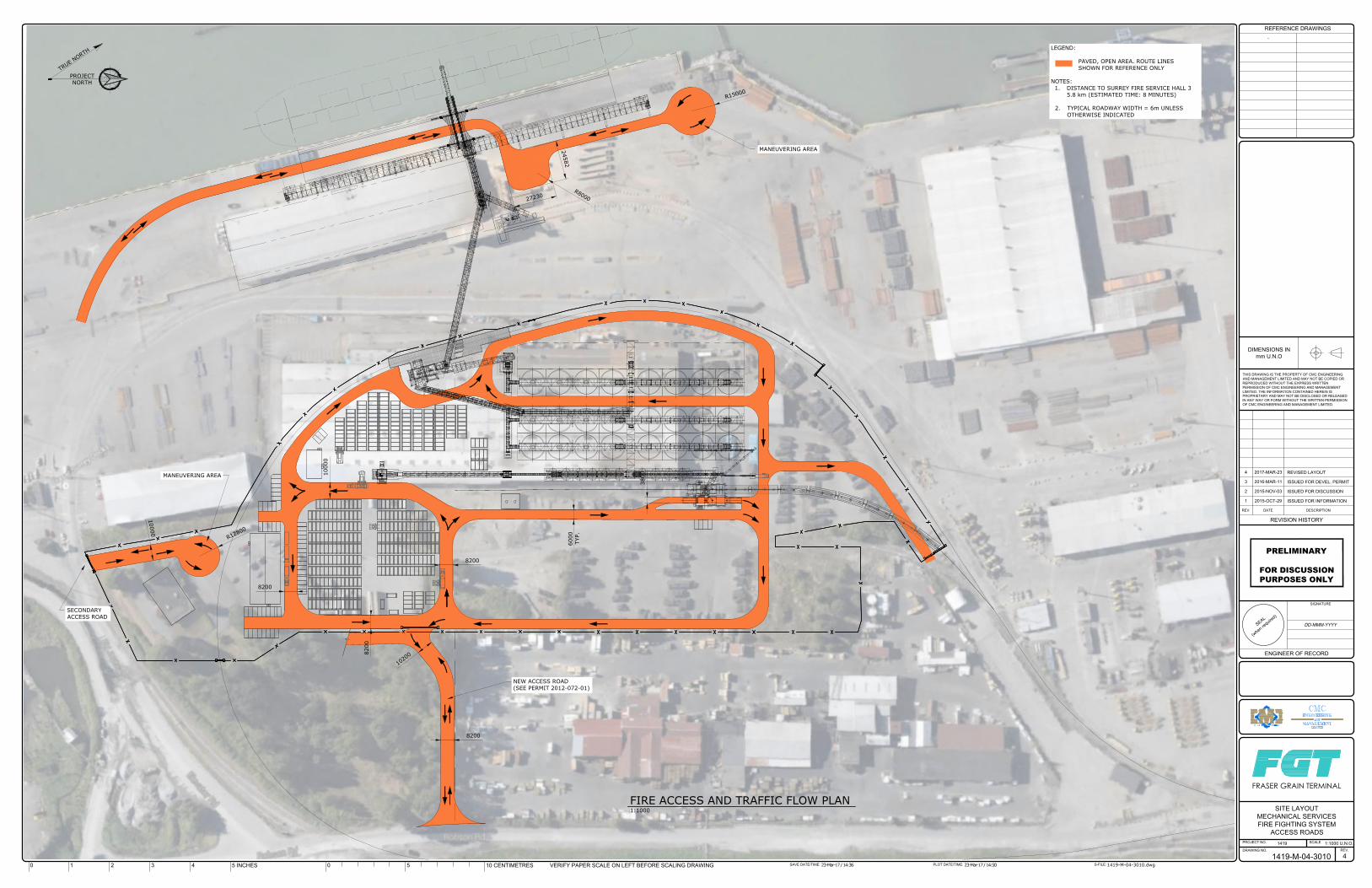
1 2 3
4
5
6
7
8
9
1 2 3
4
5
6
7
8
9
1 2015-OCT-29 ISSUED FOR INFORMATION
2 2015-NOV-03 ISSUED FOR DISCUSSION
3 2016-MAR-11 ISSUED FOR DEVEL. PERMIT
4 2017-MAR-23REVISED LAYOUT
1419-M-04-3010.dwg23-Mar-17 / 14:36 23-Mar-17 / 14:50
1419-M-04-3010
1419 1:1000 U.N.O.
SITE LAYOUT
MECHANICAL SERVICES
FIRE FIGHTING SYSTEM
ACCESS ROADS
4
DD-MMM-YYYY
PRELIMINARY
FOR DISCUSSIONPURPOSES ONLY
-
T
R
U
E
N
O
R
T
H
PROJECT
NORTH
S
E
A
L
(
w
h
e
n
r
e
q
u
i
r
e
d
)
THIS DRAWING IS THE PROPERTY OF CMC ENGINEERING
AND MANAGEMENT LIMITED AND MAY NOT BE COPIED OR
REPRODUCED WITHOUT THE EXPRESS WRITTEN
PERMISSION OF CMC ENGINEERING AND MANAGEMENT
LIMITED. THE INFORMATION CONTAINED HEREIN IS
PROPRIETARY AND MAY NOT BE DISCLOSED OR RELEASED
IN ANY WAY OR FORM WITHOUT THE WRITTEN PERMISSION
OF CMC ENGINEERING AND MANAGEMENT LIMITED.
DIMENSIONS IN
mm U.N.O
PROJECT NO.
DRAWING NO.
SCALE
REV.
S-FILE:PLOT DATE/TIME:SAVE DATE/TIME:
REVISION HISTORY
DESCRIPTIONDATEREV.
REFERENCE DRAWINGS
VERIFY PAPER SCALE ON LEFT BEFORE SCALING DRAWING10 CENTIMETRES505 INCHES43210
SIGNATURE
ENGINEER OF RECORD
FRASER GRAIN TERMINAL
LEGEND:
PAVED, OPEN AREA. ROUTE LINES
SHOWN FOR REFERENCE ONLY
NOTES:
1. DISTANCE TO SURREY FIRE SERVICE HALL 3
5.8 km (ESTIMATED TIME: 8 MINUTES)
2. TYPICAL ROADWAY WIDTH = 6m UNLESS
OTHERWISE INDICATED
R
1
5
0
0
0
6000
TYP.
8200
10000
8200
3800
8200
8200
2
7
2
3
0
2
4
5
8
2
R
8
0
0
0
MANEUVERING AREA
1
0
2
0
0
NEW ACCESS ROAD
(SEE PERMIT 2012-072-01)
SECONDARY
ACCESS ROAD
1
0
0
0
0
R
1
2
8
0
0
FIRE ACCESS AND TRAFFIC FLOW PLAN
1:1000
MANEUVERING AREA

Preliminary Review of Applicable Codes and Standards, Process Hazard Analysis and Operational Fire Safety Plan CMC Ref. 1419
S-file: 1419-204 Fire and Life V6.1.docx Page 59 of 59 Printed: 2017 06 20 17:03
ANNEX D
Water Supply and Fire Hydrants
DRAWING NO. DESCRIPTION 1419-M-04-3020 Site Layout Mechanical Services Water Supply and Fire Hydrants
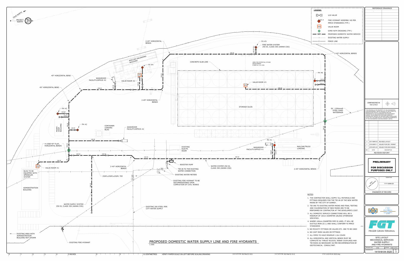
M
M
M
S
E
A
L
(
w
h
e
n
r
e
q
u
i
r
e
d
)
THIS DRAWING IS THE PROPERTY OF CMC ENGINEERING
AND MANAGEMENT LIMITED AND MAY NOT BE COPIED OR
REPRODUCED WITHOUT THE EXPRESS WRITTEN
PERMISSION OF CMC ENGINEERING AND MANAGEMENT
LIMITED. THE INFORMATION CONTAINED HEREIN IS
PROPRIETARY AND MAY NOT BE DISCLOSED OR RELEASED
IN ANY WAY OR FORM WITHOUT THE WRITTEN PERMISSION
OF CMC ENGINEERING AND MANAGEMENT LIMITED.
DIMENSIONS IN
mm U.N.O
PROJECT NO.
DRAWING NO.
SCALE
REV.
S-FILE:PLOT DATE/TIME:SAVE DATE/TIME:
REVISION HISTORY
DESCRIPTIONDATEREV.
REFERENCE DRAWINGS
VERIFY PAPER SCALE ON LEFT BEFORE SCALING DRAWING10 CENTIMETRES505 INCHES43210
SIGNATURE
ENGINEER OF RECORD
FRASER GRAIN TERMINAL
1 2016-NOV-03 ISSUED FOR DISCUSSION
2 2016-MAR-11 ISSUED FOR DEV. PERMIT
3 2017-MAR-22 REVISED LAYOUT
1419-M-04-3020.dwg2017-Mar-22 / 10:51 2017-Mar-23 / 15:15
1419-M-04-3020
1419 1:500 U.N.O.
SITE LAYOUT
MECHANICAL SERVICES
WATER SUPPLY
AND FIRE HYDRANTS
3
YYYY-MMM-DD
PRELIMINARY
FOR DISCUSSIONPURPOSES ONLY
T
R
U
E
N
O
R
T
H
PROJECT
NORTH
PROPOSED DOMESTIC WATER SUPPLY LINE AND FIRE HYDRANTS
1:500
ADMINISTRATION
BUILDING
CONTAINER
LOADING
BLDG
R
A
I
L
C
A
R
U
N
L
O
A
D
I
N
G
B
U
I
L
D
I
N
G
RAILCAR/TRUCK
LOADING
TIE-IN TO THE EXISTING
WATER CONNECTION
EX. 1200mmØ
STEEL GVRD
WATERMAIN
WASHROOM
FACILITY/OFFICE #1
WASHROOM
FACILITY/OFFICE #2
WASHROOM
FACILITY/OFFICE #3
EXISTING 200 STEEL PIPE
CITY WATER SUPPLY
WATER SYSTEM 250 DI,
CLASS 350 (AWWA CISI)
WATER SUPPLY SYSTEM
250 DI, CLASS 350 (AWWA CISI)
VR2
VR1
FIRE WATER SYSTEM
250 DI, CLASS 350 (AWWA CISI)
FH #6
FH #1
FH #5
FH #4
FH #2
VALVE ROOM #3
VALVE ROOM #2
FH #3
VALVE ROOM #1
-
2-45° HORIZONTAL BENDS
2-45° HORIZONTAL
BENDS
BOOSTER PUMP
CONCRETE SLAB LINE
250 Ø
100 Ø
100 Ø
100 Ø
250 Ø
100 Ø
2-45° HORIZONTAL
BENDS
MAIN
T.
SH
OP
BU
ILD
IN
G
150 Ø
EXISTING
ELECTR.
ROOM
250 Ø
250 Ø
250 Ø
250 Ø
250 Ø
150 Ø
150 Ø
150 Ø
AREA FOR POTENTIAL FUTURE
DEVELOPMENT
8 BINS @ 3 kt=24kt
STORAGE SILOS
2-45° HORIZONTAL BENDS
EXISTING WATER METERS
250 Ø
250 Ø
100 Ø
100 Ø
150 Ø
100 Ø
250 Ø
250 Ø
2-45° HORIZONTAL
BENDS
45° HORIZONTAL BEND
45° HORIZONTAL BEND
4-100Ø 45° FLxFL
HORIZONTAL BENDS
150 Ø
(FL)
BLDG TO BE
EQUIPPED WITH
SPRINKLER
SYSTEM
NOTES:
1. THE CONTRACTOR SHALL SUPPLY ALL MATERIALS AND
FITTINGS REQUIRED FOR THE TIE-IN OF THE NEW WATER
MAINS BY THE CITY OF SURREY.
2. TIE-INS TO EXISTING WATER MAINS AND FINAL TESTING
AND CHLORINATION OF NEW MAINS ARE TO BE
PERFORMED BY CONTRACTOR AT THE DEVELOPER'S COST.
3. ALL DOMESTIC SERVICE CONNECTIONS WILL BE A
MINIMUM OF 19mm DIAMETER UNLESS OTHERWISE
SPECIFIED.
4. WHERE 100mm DIAMETER PIPE IS USED, IT WILL BE
DUCTILE IRON (D.I.) AND SHALL CONFORM TO MMCD
STANDARDS
5. NO MCAVITY FITTINGS OR VALVES ETC. ARE TO BE USED
6. NO CAST IRON VALVES OR FITTINGS
7. ALL PIPES TO HAVE MINIMUM 1.0m COVER
8. ALL HORIZONTAL AND VERTICAL BENDS MUST BE
COMPLETE W/ THRUST BLOCKS, REBAR COUPLINGS AND
TIE-RODS AS NECESSARY AS PER RECOMMENDATION BY
GEOTECHNICAL CONSULTANT.
250FLx250FLx250FL TEE
EXISTING FIRE HYDRANT TO BE
DECOMMISSIONED UPON
COMPLETION OF CIVIL WORKS
250 Ø
EXISTING AREA WITH
ADMINISTRATION
BUILDING NOT SHOWN
EXISTING FIRE HYDRANT
LEGEND:
U/G VALVE
PROPOSED DOMESTIC WATER SERVICE
EXISTING WATER SUPPLY
FENCE LINE
FIRE HYDRANT ASSEMBLY AS PER
VRX
VALVE ROOM
FH #
MMCD STANDARDS (TYP.)
GVRD W/M CROSSING (TYP.)
VR3