Embed Size (px)
DESCRIPTION
SUMMER TRAINING REPORT AT SONA KOYO
Citation preview

NETAJI SUBHAS INSTUTUTE OF TECHNOLOGY,
University of Delhi, Delhi
Summer Training ReportSONA KOYO STEERING SYSTEMS LTD.,Gurgaon, HARYANA
[A 6-week Summer Training after completion of Second year of B.E. in Mfg. Process & Automation Engg, in Process Quality Department at Sona Koyo Steering Systems Ltd.]
PIYUSH GUPTARoll no, -637/MP/10Manufacturing Process & Automation EngineeringDate: 10th July 2012


TABLE OF CONTENTS
TITLE PAGE NO.
1. Preface 7
2. Acknowledgement 8
3. Introduction to Sona Koyo Steering System 9
4. Introduction to Steering System 16
5. Manual Steering System 20
6. Recirculating Ball Steering 23
7. Axle And DIfferential 30
8. Steering Column And Its Type 37
9. Steering System Testing 42
10. Project Work 43
9. Hydraulic Power Steering 45
10. Subparts Of Project 67
11. Kaizen And Kanban System 73
12. How this Training was helpful to Me 76
1

LIST OF FIGURES
FIGURE NO. TITLE PAGE
1.1 View of company 10
1.2 Plant locations 12
2.1 Basic steering system 17
2.2 Ackermann Steering Geometry 19
3.1 How car steering works 20
3.2 Assy. of rack and pinion 21
4.1 R.B.S. Parts 23
4.2 Working of R.B.S. 24
4.3 Final Assy. of R.B.S. 24
5.1 Differential Assembly 31
5.2 Working of Differential 32
5.3 Axle assembly 32
5.4 Universal Joint 35
6.1 Steering Column 38
6.2 Steering wheel with column 39
6.3 Collapsible Steering 40
2

FIGURE NO. TITLE PAGE
7.1 Track for steering testing 42
7.2 Endurance Testing Actuater 42
8.1 Basic steering system 44
9.1 Assembled view of power steering 45
9.2 Power rack and pinion steering 46
9.3 Rotary vane pump 47
9.4 Rotary Valve 49
9.5 Process of centerless grinding 53
9.6 Flat milling machine 54
9.7 Broaching tool 55
9.8 Induction hardening 56
9.9 Induction tempering process 57
9.10 Process of stone lapping 58
9.11 Process of paper lapping 59
9.12 Centering and facing on pinion 60
9.13 Pinion rod 60
9.14 Turning process 61
9.15 Serration rolling 61
3

FIGURE NO. TITLE PAGE
9.16 Grinding process 62
9.17 Hobbing done on pinion 62
9.18 Leakage testing machine 65
9.19 Complete H.P. Steering 66
10.1 Leakage testing machine 67
10.2 Outer ball joint 68
10.3 Collet Gun and Collet Chuck 69
10.4 Forward and reverse input testing 70
10.5 Honning machine 71
10.6 Pinion 72
4

PREFACE
As a student of Netaji Subhas Institute of Technology, I have attended six weeks Industrial
Training after my second year from 4th June,12 to 10th July,12 to get a better knowledge of industrial atmosphere and floor work. As a part of it, I went for the six week Industrial training at SONA KOYO STEERING SYSTEM at Gurgaon to gain some practical and shop floor experience. These give me the opportunity to have an exposure to experience and to interact with engineers, supervisors and workers.
During the training, I went for that discipline, sense of responsibility, orderliness, proper communication, leadership guidance are necessary to convert company or organization objectives into products/services through channel called production. The changing industrial scenario and environment needs trained and experienced engineers who can affectively handle the manpower without many grievances and ensure the effective utilization of machines and materials to achieve the objectives laid down by the organization. Accordingly engineers find placement in respective field such as Research and development, Designing, Production, Inspection, Quality control, Marketing, Maintenance, Material handling etc.
I might not have understood all the procedures and process of industry but I have tried my best to gain practical knowledge from this training. I think that this training has proved to be beneficial in upcoming life.
5

ACKNOWLEDGEMENT
It brings me immense pleasure for an opportunity to have undergone training at Sona KoyoSteering Systems Limited.
I would like to thank my training supervisor Mr. Vijay Sethi for his valuable guidance throughout my training. I would also like to thank the entire Quality Assurance Department especially Process Quality Department in which I have undergone my training for the help extended to me through the course of my training. I would also like to thank Mr. Rakesh Bansal and Mr. Krishan Rohilla for their invaluable support.
There is always a sense of gratitude which one expresses to others for their helpful and needy services, which they render during all phases of life. I would like to do the same as I really wish to express my gratitude towards all those who have been helpful to me during different stages of my Industrial training and encouraged me with their ideas and views, which were guiding and motivating factors in completion of mighty and tedious tasks of project report writing to be a success.
In presenting this Report I would like to convey my deep and profound gratitude towards all Engineers and Operators at Sona Koyo Steering Systems Limited for their co-operation and guidance.
PIYUSH GUPTANSIT, DWARKANew Delhi
6

Introductionto
Sona Koyo Steering SystemsLtd.
7

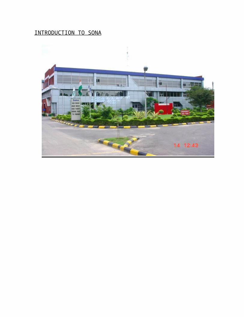
INTRODUCTION TO SONA
Figure 1.1: View of company
With its beginning as a small company in 1987, now the $80 million SONA Group comprises
several companies each of which are in joint venture partnerships and technical and financial
collaboration with global leaders in their specialist areas. Sona Koyo Steering Systems Limited
(SKSSL) is a technical and financial joint venture company of Koyo Seiko Company, Japan.
With a Market share of 50%, the company is the largest manufacturer of steering gears in India
and is the leading supplier of:
Hydraulic Power Steering Systems
Manual Rack & Pinion Steering Systems
Recirculating Ball Steering, propeller shaft, Differential Assy.
Collapsible, Axle Assy., Tilt and Rigid Steering Columns for Passenger Vans and MUV’s.
8

MILESTONE OF SONA GROUP
9

PLANT LOCATION
PLANT-1 PLANT- 2
PLANT-3 Figure 1.2: Plant locations PLANT-4
Total Site Production Commenced - 56970 m2
Plant –1 R&P Steering Gear 2933 m2
Steering Column
Plant-2 RBS Steering Gear 5363 m2
Axle and Prop Shaft, Diff. AssyPlant –3 R&P Power Steering 1265 m2
Plant-4 Case differential, Collapsible 2213 m2
column, Uj,Others Utilities, Stores etc. 1330 m2
Certification QS 9000, ISO 14001, TS16949
10
CUSTOMERS
11

PRODUCTS
PLANT-1
1) RPS Assembly Manual (TOYOTA) 2) RPS Assembly Manual (MARUTI 800) 3) Collapsible Column (SAFARI) 4) Collapsible Column (YE-2R) 5) Collapsible Column (MODEL-A) 6) Collapsible Column (SCORPIO)
PLANT-2
1) Shaft Propeller Assembly 2) RBS Assembly (OMNI,GYPSY) 3) Case Differential Assembly (TELCO) 4) Case Differential Assembly (OMNI) 5) Case Differential Assembly (YE-2R) 6) Axle Assembly (OMNI,GYPSY) 7) Sector Shaft Assembly
PLANT-3
1) Hydraulic Power Steering(all models)
PLANT-4
1) Case Differential (SWIFT) 2) Collapsible Column (MARUTI 800) 3) Column Assembly (ALTO) 4) IMV Column (INNOVA) 5) Column Assembly (OMNI)
6) Column Assembly (SCORPIO)
12
SONA KOYO WORKING PHILOSOPHY
SONA KOYO respects the dignity of human beings at all levels. In the matter of employment, it
believes in the concept of equality in caste, religious, creed., race, sex and nationality.
Employees selection shall be merit based and made on basis of proven ability of the
incumbents(s).
SONA KOYO endeavors to provide equal opportunity to all and one in the matter of internal
promotion. Only the right person for the right job however, shall be promoted.
SONA KOYO is conscious of fact that the growth an d progress of its employees and the
company is inter –dependent, hence the concept of all round development of its team members
shall be of prime importance.
SONA KOYO encourages meaningful participation of its team members to achieve the
organizational goals and objectives.
SONA KOYO constantly endeavors to establish and promotes clean and safe working
environment where it team members may work happily and drive joy and pleasure.
SONA KOYO shall encourage and promote sports and such other cultural activities, which may
be useful in building the moral values and national character of honest, discipline and integrity
among its team member.
SONA KOYO as a good cooperate citizen shall like to participate in the community
development and welfare programs in its surroundings areas so as to develop understanding and
generate goodwill amongst the inhabitancy of local society.
13

Introduction
to
Steering Systems
14

INTRODUCTION TO STEERING
Steering is the term applied to the collection of components, linkages, etc. which will allow
a vessel(ship, boat) or vehicle (car, motorcycle, bicycle) to follow the desired course. An
exception is the case of rail transport by which rail tracks combined together with railroad
switches (and also known as 'points' in British English) provide the steering function.
The most conventional steering arrangement is to turn the front wheels using a hand–
operated steering wheel which is positioned in front of the driver, via the steering column, which
may contain universal joints (which may also be part of the collapsible steering column design),
to allow it to deviate somewhat from a straight line. Other arrangements are sometimes found on
different types of vehicles, for example, a tiller rear–wheel steering. Tracked vehicles such as
bulldozers and tanks usually employ differential steering — that is, the tracks are made to move
at different speeds or even in opposite directions, using clutches and brakes, to bring about a
change of course or direction.
Figure 2.1: Basic steering system
15
PURPOSE OF STEERING SYSTEMS
The purpose of the steering system is to allow the driver to control the direction of the vehicle by
turning the front wheels. Together with the suspension system, it plays an important role in
ensuring easy, comfortable driving all the way from the low speed range to the high-speed
ranges.
A good and efficient steering system has to ensure the following:
1. Excellent Maneuverability : When the car is cornering on a narrow, twisting road, the
steering system must be able to turn the front wheels sharply yet easily and smoothly.
2. Proper Steering Effort : If nothing is done to prevent it, steering effort will be greater
when the car is stopped and will decrease as the speed of the car increases. Therefore, in
order to obtain easier steering and better feel of the road, the steering should be made
lighter at low speeds and heavier at high speeds.
3. Smooth Recovery : While the car is turning, the driver must hole the steering wheel
firmly. After the turn is completed, however, recovery- that is, the return of the wheels to
the straight-ahead position- should occur smoothly as the driver relaxes the force with
which he is turning the steering wheel.
4. Minimum transmission of Shock from Road Surface : Loss of steering wheel control
and transmission of kickback due to road surface must not occur.
16

BASIC GEOMETRY
The basic aim of steering is to ensure that the wheels are pointing in the desired directions. This is typically achieved by a series of linkages, rods, pivots and gears. One of the fundamental concepts is that of caster angle - each wheel is steered with a pivot point ahead of the wheel; this makes the steering tend to be self-centering towards the direction of travel.
The steering linkages connecting the steering box and the wheels usually conforms to a variation of Ackermann steering geometry, to account for the fact that in a turn, the inner wheel is actually traveling a path of smaller radius than the outer wheel, so that the degree of toe suitable for driving in a straight path is not suitable for turns. The angle the wheels make with the vertical plane also influences steering dynamics (see camber angle) as do the tires.
Figure 2.2: Ackermann Steering Geometry
17

Manual Steering Systems
RACK-AND-PINION STEERING:
Rack-and-pinion steering is quickly becoming the most common type of steering on cars, small
trucks and SUVs. It is actually a pretty simple mechanism. A rack-and-pinion gear set is enclosed
in a metal tube, with each end of the rack protruding from the tube. A rod, called a tie rod,
connects to each end of the rack.
Figure 3.1: How car steering works
18

ASSEMBLY VEIW OF RACK AND PINION STEERING
Figure 3.2: Assy.of rack and pinion
The pinion gear is attached to the steering shaft. When you turn the steering wheel, the gear
spins, moving the rack. The tie rod at each end of the rack connects to the steering arm on the
spindle (see diagram above).
The rack-and-pinion gear set does two things:
(1) It converts the rotational motion of the steering wheel into the linear motion needed to turn
the wheels.
(2) It provides a gear reduction, making it easier to turn the wheels.
On most cars, it takes three to four complete revolutions of the steering wheel to make the wheels
turn from lock to lock (from far left to far right).
The steering ratio is the ratio of how far you turn the steering wheel to how far the wheels turn.
For instance, if one complete revolution (360 degrees) of the steering wheel results in the wheels
of the car turning 20 degrees, then the steering ratio is 360 divided by 20, or 18:1. A higher ratio
means that you have to turn the steering wheel more to get the wheels to turn a given distance.
However, less effort is required because of the higher gear ratio. Generally, lighter, sportier cars
have lower steering ratios than larger cars and trucks.
19

SPECIAL FEATURES OF RACK AND PINION STEERING
(1) Inexpensive:-Generally when rack and pinion steering is used the gearbox is fitted into the steering link structure. The Linkages are very much reduced because the RPS is complete in itself. Therefore the cost is much cheaper with respect to other types.
(2) Light in weight:-As a steering gear assembly the no. of linkages are less. From the angle of strength the material of gearbox is aluminum die cast compared to RBS, it is light in weight.
(3) A Sharp Steering feeling:- In the case of RBS type steering the torque applied to main shaft goes through the Ball Screw to Ball Nut and then to Sector Gear. Vis a Vis the RPS where Rack and Pinion are in direct contact therefore, the feeling is sharper in response. At high speed driving there is a direction in the handle is steady and a sharp response can be need where the steering handle is turned.
(4) Strength is high:- In the RPS type the meshing force between the teeth of the gears is lower in comparison to the RBS type, therefore the impact strength can be higher.
(5) Noise and nitration counter measure :- The gear portion and the rack bush in the RPS steering are the negative points of the RPS steering as compared to the RBS type, the noise through their interference and the vibration arising due to type and the steering line portion and rack bush. By the usage of anti vibration ball joints a satisfactory fitting can be had.
20

RECIRCULATING BALL STEERING
Recirculating ball steering is used on many trucks and SUVs today. The linkage that turns the
wheels is slightly different than on a rack-and-pinion system.
Figure 4.1: R.B.S. Parts
The re-circulating-ball steering gear contains a worn gear you can image the gear in two parts.
The first part is a block of metal with a threaded hole in it. This block has gear teeth cut into the
outside of it, which engage a gear that moves the pitman arm (see diagram above).
The steering wheel connects to a threaded rod, similar to a bolt, that sticks into the hole in the
block. When the steering wheel turns, it turns the bolt. Instead of twisting further into the block
the way a regular bolt would, this bolt is held fixed so that when it spins, it moves the block,
which moves the gear that turns the wheels.
21

Instead of the bolt directly engaging the threads in the block, all of the threads are filled with ball
bearing that recirculate through the gear as it turns. The balls actually serve two purposes: First,
they reduce friction and wear in the gear; second, they reduce slop in the gear. Slop would be felt
when you change the direction of the steering wheel without the balls in the steering gear, the
teeth would come out of contact with each other for a moment, making the steering wheel feel
loose.
Figure 4.2: Working of R.B.S.
COMPLETE & EXPLODED VIEW OF RBS
Figure 4.3: Final Assy. of R.B.S.
22

SPECIAL FEATURES OF RECIRCULATING BALL STEERING
(1) Handle is light :-Highly efficient (about 85%), very light, very little fatigue even in long distance driving. Especially our patented product of variable ratio steering. Even when full rotation of the steering wheel is required the handle is still light. In the neutral position the steering has a very sharp response, the steering feeling at low speed and high speed is extremely good.
(2) Stability is good:- Appropriate gear ratio has been achieved through research in design and along with the guarantee of a comfortable driving and exceptional stability at high speeds can be achieved with the employment of variable ratio gear.
(3) Dependability: -Turning of the handle is very smooth, especially at high speeds the dependability and certainty of turning is very high.
(4) High Endurance of Safety: The critical parts have been selected through extensive tests and are of high qualities carburised steel and with the help of highly balanced design. The parts are exceptional in anti impact qualities and the wear is very little even in long term use.
Merits of the Recirculating-Ball Type steering gear
1. Efficiency is high (about 85%), making it light and causing a very little fatigue, even in
long distance travel.
2. It is more stable at higher speeds.
3. It has high endurance making the wear low even in long-term use.
4. Turning of the handle is very smooth, thus the dependability and certainty of turning is
very high.
23

STEER BY WIRE
The aim of steer-by-wire technology is to completely do away with as many mechanical components (steering shaft, column, gear reduction mechanism, etc.) as possible. Completely replacing conventional steering system with steer-by-wire holds several advantages, such as:
The absence of steering column simplifies the car interior design.
The absence of steering shaft, column and gear reduction mechanism allows much better space utilization in the engine compartment.
The steering mechanism can be designed and installed as a modular unit.
Without mechanical connection between the steering wheel and the road wheel, it is less likely that the impact of a frontal crash will force the steering wheel to intrude into the driver's survival space.
Steering system characteristics can easily and infinitely be adjusted to optimize the steering response and feel.
As of 2007 there are no production cars available that rely solely on steer-by-wire technology due to safety, reliability and economic concerns, but this technology has been demonstrated in numerous concept cars and the similar fly-by-wire technology is in use in both military and civilian aviation applications. Removing the mechanical steering linkage in road going vehicles would require new legislation in most countries.
24

ARTICULATED STEERING
Articulated steering is a system by which a four-wheel drive vehicle is split into front and rear halves which are connected by a vertical hinge. The front and rear halves are connected with one or more hydraulic cylinders that change the angle between the halves, including the front and rear axles and wheels, thus steering the vehicle. This system does not use steering arms, king pins, tie rods, etc. as does four-wheel steering. If the vertical hinge is placed equidistant between the two axles, it also eliminates the need for a central differential, as both front and rear axles will follow the same path, and thus rotate at the same speed. Long road trains, articulated buses, and internal transport trolley trains use articulated steering to achieve smaller turning circles, comparable to those of shorter conventional vehicles. Articulated haulers have very good off-road performance.
25

REAR WHEEL STEERING
A few types of vehicle use only rear wheel steering, notably fork lift trucks, camera dollies, early pay loaders, Buckminster Fuller's Dymaxion car, and the ThrustSSC.[6]
Rear wheel steering tends to be unstable because in turns the steering geometry changes hence decreasing the turn radius (oversteer), rather than increase it (understeer). A rear wheel steered automobile exhibits non-minimum phase behavior.[7] It turns in the direction opposite of how it is initially steered. A rapid steering input will cause two accelerations, first in the direction that the wheel is steered, and then in the opposite direction: a "reverse response." This makes it harder to steer a rear wheel steered vehicle at high speed than a front wheel steered vehicle
26

SAFETY REGARDING STEERING
For safety reasons all modern cars feature a collapsible steering column (energy absorbing steering column) which will collapse in the event of a heavy frontal impact to avoid excessive injuries to the driver. Airbags are also generally fitted as standard. Non-collapsible steering columns fitted to older vehicles very often impaled drivers in frontal crashes, particularly when the steering box or rack was mounted in front of the front axle line, at the front of the crumple zone. This was particularly a problem on vehicles that had a rigid separate chassis frame, with no crumple zone. Most modern vehicle steering boxes/racks are mounted behind the front axle on the front bulkhead, at the rear of the front crumple zone.
Collapsible steering columns were invented by Bela Barenyi and were introduced in the1959 Mercedes-Benz W111 Fintail, along with crumple zones. This safety feature first appeared[when?] on cars built by General Motors after an extensive and verypublic lobbying campaign enacted by Ralph Nader. Ford started to install collapsible steering columns in 1968.[8]
Audi used a retractable steering wheel and seat belt tensioning system called procon-ten, but it has since been discontinued in favor of airbags and pyrotechnic seat belt pre-tensioners
27
Axle and Differential
28

Rear Axle
DIFFERENTIAL OPERATION:
The differential is the thing that works both drive axles at the same time, but lets them rotate at different speeds so that the car can make turns. When a car makes a turn, the outer wheel has to turn faster than the inner wheel, due to the difference in the length of the paths they take. The differential is located between the two wheels, and is attached to each wheel by a half-shaft rotated through a bevel gear. Four-wheel drive cars have a separate differential for each pair of wheels.
Figure 5.1: Differential Assembly
A grooved, or splined, axle side gear is positioned on the splined end of each axle. The side gears are driven by "spider" gears, which are little gears mounted on a shaft attached to the differential case. As it is supported by the differential case, the side gear can turn inside the case.
The differential case can be turned, revolving around the axle gears. The differential pinion (a pinion is a small gear that either drives a larger gear or is driven by one) shaft turns the ring gear, which is fastened to the differential case. The propeller shaft (drive shaft) connects the transmission output shaft to the differential pinion shaft. The turning differential case is mounted on two large bearing holders. These bearings are called carrier bearings.
29

Working of Differential Unit
Figure 5.2: Working of Differential
The propeller shaft rotates the ring gear pinion, and the pinion turns the ring gear. The ring gear then turns the differential case and pinion shaft, but the axle side gears will not turn. By passing the differential pinion shaft through two differential pinion gears that mesh with the side gears, the case will turn and the axle side gears will turn with it. During turns, the side gears turn at rates dictated by the radius of the turns, and the spider gears then turn to allow the outer wheel to turn faster than the inner one.
Figure 5.3: Axle assembly
30

Differential Fluids
For lubrication fluid, very heavy oil must be used in rear axle housings. Special hypoid oils are used in the differential case. Even another type of fluid or oil must be used in a posit action type differential.
The oil is circulated by the ring gear, and flung all over all the parts. Special troughs or gullies are used to bring the oil back to certain spots, like the ring and pinion area and the piston bearings. The fluid is kept in with gaskets and oil seals. The bottom of the housing has a drain plug, and another filler plug is located part way up the housing. The housing must never be filled above this plug.
The housing fluid lubricates some of the outer bearings, but others have lubrication fittings for the injection of wheel bearing grease. A handgun, not a pressure grease gun must be used to grease these bearings (sparingly). A pressure grease gun could inject grease into the brakes-- greasy brakes are inefficient at best!
Finally, some bearings are filled with grease at the factory and are sealed. These never require attention unless they are defective.
31

The Drive Shaft
The drive shaft, or propeller shaft, connects the transmission output shaft to the differential pinion shaft. Since all roads are not perfectly smooth, and the transmission is fixed, the drive shaft has to be flexible to absorb the shock of bumps in the road. Universal, or "U-joints" allow the drive shaft to flex (and stop it from breaking) when the drive angle changes.
Drive shafts are usually hollow in order to weigh less, but of a large diameter so that they are strong. High quality steel, and sometimes aluminum are used in the manufacture of the drive shaft. The shaft must be quite straight and balanced to avoid vibrating. Since it usually turns at engine speeds, a lot of damage can be caused if the shaft is unbalanced, or bent. Damage can also be caused if the U-joints are worn out.
There are two types of drive shafts, the Hotchkiss drive and the Torque Tube Drive. The Hotchkiss drive is made up of a drive shaft connected to the transmission output shaft and the differential pinion gear shaft. U-joints are used in the front and rear. The Hotchkiss drive transfers the torque of the output shaft to the differential. No wheel drive thrust is sent to the drive shaft. Sometimes this drive comes in two pieces to reduce vibration and make it easier to install (in this case, three U-joints are needed). The two-piece types need ball bearings in a dustproof housing as center support for the shafts. Rubber is added into this arrangement for noise and vibration reduction.
32

The Universal Joint (U-joint)
Figure 5.4: Universal Joint
The Universal joint (U-joint) is used to connect the drive shaft to the transmission output shaft and the Differential pinion gear shaft. This joint must be flexible enough to allow changes in the driving angle (road incline) and the drive shaft. This way, the torque is constantly transmitted when the rear axle is moving up and down. Smaller U-joints are used to route the turning motion of the steering wheel through the steering column to the steering box.
There are two types of U-joints, the cross and roller type and the ball type. The cross and roller type is used the most; it allows the drive shaft to bend. The ball and trunnion type less frequently used; it allows the drive shaft to bend and also permits backward and forward motion of the drive shaft.
33

UNIVERSAL JOINT ASSEMBLY MACHINE
MAJOR PROBLEMS
S.NO. PROBLEMS CAUSES COUNTERMEASURES1 Incomplete Bearing Misalignment of Fixture alignment to be done
Press Fixture properly.2 Stacking Out Slipping of Yoke Yoke to be placed properly in
From Fixture, Due the fixture.to BOP
3 Jerky Movement of Bearing Needle Avoid use of Rusty Spider,Bearing Fall, Rusty spider, Stacking force should be less.
More staking force4 Yoke expansion Spider Tolerance, Spiders of equal tolerance
Excess Widening of should be made available.Claws
5 Leg Bend Incomplete Bearing Application of correctPress, Slipping of stacking force, Place YokeYoke properly.
6 Articulating Torque Increase/Decrease To be done manually by theMore/Less in Widening operating the Joint Assembly
Distance of Claws Machine.7 Bearing crack Misalignment of Fixture alignment to be done
Fixture properly.
MINOR PROBLEMS
S.NO. PROBLEMS COUNTERMEASURES1 Loosening of Side Wedge To be done manually2 Breakage of Union Pipe Replacement of New Union
Connected with Pneumatic PipeCylinder
3 Stuck-up of Bearings Apply Air Pressure4 Falling of Bearings during Replacement of Cassette of
Inversion of Cassettes suitable size
34

Steering Columnsand its Types
35

COLLAPSIBLE COLUMN
In recent times with increase in automobile accidents, the progress of research into how far the life of the driver can be protected has resulted in the development of a new product called collapsible column (Impact absorbing type column), In case of an automobile accident where the chart of the driver strike the handle and due to the collapsing nature of the handle the shock of the impact is reduced thereby preventing a death in the accident. In our country from 1stOct’1973 a rule was implemented which specifies that all the automobiles sold in the domestic market must have the above mentioned impact absorbing handle. In other words it’s a contraption, which has been made as a product because of safety regulations. Our company developed a product, which matched well with the impact features of the vehicle under special license from G.M. for the 1st makers of the automobile in the World. Our company started using it on 1200cc Honda in 1972 and as such the history of the product is very. But our company’sR&D has brought up the product as a high technology, high safety and presently due to the independent development of collapsible column by our company, it is being used in Mitsubishi Debonair, Diamate, Sherio, GTO and Suzuki Alto.
(1) Functions, which a collapsible column must have :-In case of an accident a collapsible column must have the ability to abort the shock due to the impact on the handle when the driver strikes. Along side being a product when protects the drivers it must have the function of normal steering. Legally it should satisfy safety regulations (FMVSS-203). In the experimentation rooms the column must satisfy and collapse at force of 1135 Kgf due to the burst portion of the dummy body strike.
(2)Structure:-The collapsible column is an apparatus, which absorbs the impact to the body from the handle at the time of collision and the structural parts, are column, Jacket, steering shaft column bracket etc.
Figure 6.1: Steering Column
36

FUNCTIONS OF STEERING COLUMN
A steering column performs the following functions:
(1) The automotive steering column is a device intended primarily for connecting the steering wheel to the steering mechanism or transferring the driver's input torque from the steering wheel.
(2) The energy dissipation management in the event of a frontal collision;
(3) It provide mounting for: the multi-function switch, column lock, column wiring, column shroud(s), transmission gear selector, gauges or other instruments as well as the electro motor.
(4) It offer (height and/or length) adjustment to suit driver preference.
SteeringWheel
SteeringColumn
Figure 6.2: Steering wheel with column
37

TYPES OF STEERING COLUMNS
There are two types of steering columns are manufactured in Sona.
1. Energy absorbing collapsible steering columns
2. Rigid steering columns.
1. Energy absorbing collapsible steering columns : They are designed for mass
production and best suitable for stabilized Load at time of impact absorption. These
types of columns break when load of more than 170 to 190 kgf are applied on it.
Figure 6.3: Collapsible Steering
2. Rigid steering columns: This type of steering columns is used with or without
universal joints. It transmits torque from the steering wheel to the steering gear. These
columns are used in MARUTI and OMNI.
38

Paint Shop
SKSSL has a paint shop for catering to its in-house demand of painting of various components.
The shop is located in Plant II and paints about 100 pieces per hour, working one shift a day. The
cycle time for painting each component is about 2 hours and 45 minutes. The main components
that are painted in the shop are propeller shaft, RBS Assy, I-Shaft Assy, lower shaft and
collapsible column. The main activities that are carried on in the paint shop in the order of taking
place are:
1. Degreasing : Degreasing is the process of removing rust, chemicals etc. from the surface
of the component by washing it in alkaline powder solution (pH 12) in the degreasing
tank. The solution is changed once a month.
2. Water rinsing : It is the process of washing off the degreasing solution from the surface of
the component. This is basically washing the piece in water of pH between 7 and 8. This
water is replaced daily.
3. Activation : This is a prerequisite to the phosphatising process. Here the component is
treated with a solution of Ultra Act-C (of pH 8-9)
4. Phosphatising : This process is important because it makes sure that the paint sticks to the
component and does not remove easily. Here the component is sprayed with a solution of
Ultra-Bond 5P and accelerator. The solution is changed once a month.
5. Washing : Here the component is washed in DM water.
6. Drying : After washing, the component passes through a furnace (oven) where the
moisture and water on the surface is dried.
7. Painting : The components are spray painted one-by-one manually by the operator.
8. Drying : The paint is then dried by passing it again inside the oven. The time spent by the
component in the oven this time is twice that of the time spent before painting.
39

Track for Steering System Testing
Track for Noise Test Figure ‘8’ for Steering Effort
Figure 7.1: Track for steering testing
Figure 7.2: Endurance Testing Actuater
40

PROJECT WORKAT
SONA KOYO STEERING SYSTEM
LIMITED

41

Project: To Study and Solve the Problems occurs in Hydraulic Power Steering Assembly Lines and To Increase Production.
STEERING SYSTEM
Figure 8.1: Basic steering system
DESCRIPTION:The rotary motion of the steering hand wheel is changed to the linear motion of the drag link
through the steering gear box & pitman arm. The drag link pulls & pushes the steering center
level. So that this lever turns the right and left front wheels around their kingpins through the two
tie rods and knuckle arm.
The whole system has a self restoring property & is designed for easy steering and high
durability. The self restoring action is reliable the operating effort required for turning the hand
wheel is small & the system components are easy to service. The rotary joints of the steering
linkage are of ball & socket type. There are mainly three types of steering systems manufactured
in Sona.
Rack & Pinion type manual steering system
Re-circulating ball screw type manual steering system
Rack & Pinion type power steering system.
42

HYDRAULIC POWER STEERING
NECESSITY: To improve the driving comfort, most modern automobiles have wide, low-
pressure tires that increase the tire-to-road surface contact area. As a result, more steering
effort is required. Even though the steering effort can be decreased by increasing the gear
ratio of the steering gear, this will make sharp turns impossible. Thus, a steering assist is
required in the passenger cars as well.
PinionOuter ball Outer ballHydraulic
joint jointFluid lines cylinder
Pinionhousing
Inner ball
joint Inner ballBellows joint
Figure 9.1: Assembled view of power steering
43

POWER RACK AND PINION STEERING
When the rack-and-pinion is in a power-steering system, the rack has a slightly different design.
Part of the rack contains a cylinder with a piston in the middle. The piston is connected to the
rack. There are two fluid ports, one on either side of the piston. Supplying higher-pressure fluid
to one side of the piston forces the piston to move, which in turn moves the rack, providing the
power assist.
Figure 9.2: Power rack and pinion steering
Working of Power Steering Mechanism:
Power Steering is an assist device that helps keep the steering agile and at the same keeps the
steering effort small. SONA manufactures the rack and pinion type power steering mechanism,
which is primarily used in passenger cars. Power rack and pinion steering assemblies are
hydraulic/mechanical unit with an integral piston and rack assembly. An internal rotary valve
directs power steering fluid flow and controls pressure to reduce steering effort. The rack and
pinion is used to steer the car in the event of power steering failure, or if the engine (that drives
the pump) stalls. When the steering wheel is turned, resistance is created by the weight of the car
and tire-to-road friction, causing a torsion bar in the rotary valve to deflect. This changes the
position of the valve spool and sleeve, thereby directing fluid under pressure to the proper end of
the attached to the rack) helps move the rack to reduce turning effort. The fluid in the other end
of the power cylinder is forced to the control valve and back to the pump reservoir. When the
steering effort stops, the control valve is centered by the twisting force of the torsion bar.
44

PUMP
The hydraulic power for the steering is provided by a rotary-vane pump.
Figure 9.3: Rotary vane pump
This pump is driven by the car's engine via a belt and pulley. It contains a set of retractable vanes
that spin inside an oval chamber.
As the vanes spin, they pull hydraulic fluid from the return line at low pressure and force it into
the outlet at high pressure.
45

The amount of flow provided by the pump depends on the car's engine speed. The pump must be
designed to provide adequate flow when the engine is idling. As a result, the pump moves much
more fluid than necessary when the engine is running at faster speeds.
The pump contains a pressure-relief valve to make sure that the pressure does not get too high,
especially at high engine speeds when so much fluid is being pumped.
46

ROTARY VALVE
A power-steering system should assist the driver only when he is exerting force on the steering
wheel (such as when starting a turn). When the driver is not exerting force (such as when driving
in a straight line), the system shouldn't provide any assist. The device that senses the force on the
steering wheel is called the rotary valve.
Figure 9.4: Rotary Valve
The key to the rotary valve is a torsion bar. The torsion bar is a thin rod of metal that twists
when torque is applied to it. The top of the bar is connected
to the steering wheel, and the bottom of the bar is connected to the pinion or worm gear (which
turns the wheels), so the amount of torque in the torsion bar is equal to the amount of torque the
driver is using to turn the wheels. The more torque the driver uses to turn the wheels, the more
the bar twists.
47

The input from the steering shaft forms the inner part of a spool-valve assembly. It also connects
to the top end of the torsion bar. The bottom of the torsion bar connects to the outer part of the
spool valve. The torsion bar also turns the output of the steering gear, connecting to either the
pinion gear or the worm gear depending on which type of steering the car has.
As the bar twists, it rotates the inside of the spool valve relative to the outside. Since the inner
part of the spool valve is also connected to the steering shaft (and therefore to the steering
wheel), the amount of rotation between the inner and outer parts of the spool valve depends on
how much torque the driver applies to the steering wheel.
When the steering wheel is not being turned, both hydraulic lines provide the same amount of
pressure to the steering gear. But if the spool valve is turned one way or the other, ports open up
to provide high-pressure fluid to the appropriate line.
It turns out that this type of power-steering system is pretty inefficient. Let's take a look at some
advances we'll see in coming years that will help improve efficiency
48

Manufacturing Processes inHydraulic Power Steering
Assembly
49

THE MAIN PARTS OF HYDRAULIC POWER STEERING ASSEMBLY ARE
(1)POWER RACK BAR ASSEMBLY LINE
(2) HYDRAULIC CYLINDER LINE
(3)POWER PINION LINE
(4)FINAL H.P.S. ASSEMBLY LINE
50

POWER RACK BAR LINE
(1) CENTERLESS GRINDING MACHINE:- Centerless grinding is a method ofmaterial removal through grinding, similar to centered grinding except for the absence of the spindle. It has high throughput, i.e., a large number of parts can be manufactured in a short time.
The workpiece is set up between the regulating wheel (or back up wheel) and the grinding wheel, and is supported by the work blade or work rest. The work rest is located between the wheels. The work is placed on the work rest, and the latter together with the regulating wheel is fed forward forcing the work against the grinding wheel. Axial movement of the work past the grinding wheel is accomplished by tilting the regulating wheel at a slight angle from horizontal. An angular adjustment of 0 to 8 or 10 degrees is provided in the machine for this purpose.
Figure 9.5: Process of centerless grinding
51

(2) FLAT MILLING:- A milling machine is a machine tool used to machine solid materials. Milling machines are often classed in two basic forms, horizontal and vertical, which refers to the orientation of the mainspindle. Both types range in size from small, bench-mounted devices to room-sized machines. Unlike a drill press, which holds the workpiece stationary as the drill moves axially to penetrate the material, milling machines also move the workpiece radially against the rotating milling cutter, which cuts on its sides as well as its tip. Workpiece and cutter movement are precisely controlled to less than 0.001 in (0.025 mm), usually by means of precision ground slides and lead screws or analogous technology. Milling machines may be manually operated, mechanically automated, or digitally automated via computer numerical control.Milling machines can perform a vast number of operations, from simple (e.g., slot and keyway cutting, planing, drilling) to complex (e.g., contouring, diesinking). Cutting fluid is often pumped to the cutting site to cool and lubricate the cut and to wash away the resulting swarf.
Figure 9.6: Flat milling machine
52

(3) RACK TEETH BROACHING:- Broaching is a machining process that uses a toothed tool, called a broach, to remove material. There are two main types ofbroaching: linear and rotary. In linear broaching, which is the more common process, the broach is run linearly against a surface of the workpiece to effect the cut. Linear broaches are used ina broaching machine, which is also sometimes shortened tobroach. In rotary broaching, the broach is rotated and pressed into the workpiece to cut an axis symmetric shape. A rotary broach is used in a lathe or screw machine. In both processes the cut is performed in one pass of the broach, which makes it very efficient.
Broaching is used when precision machining is required, especially for odd shapes. Commonly machined surfaces include circular and non-circular holes, splines, keyways, and flat surfaces. Typical workpieces include small to medium sized castings, forgings, screw machine parts, and stampings. Even though broaches can be expensive, broaching is usually favored over other
processes when used for high-quantity production runs.[1]
Broaches are shaped similar to a saw, except the teeth height increases over the length of the tool. Moreover, the broach contains three distinct sections: one for roughing, another for semi-finishing, and the final one for finishing. Broaching is an unusual machining process because it has the feed built into the tool. The profile of the machined surface is always the inverse of the profile of the broach. The rise per tooth (RPT), also known as the step or feed per tooth, determines the amount of material removed and the size of the chip. The broach can be moved relative to the workpiece or vice-versa. Because all of the features are built into the broach no
complex motion or skilled labor is required to use it.[2] A broach is effectively a collectionof single-point cutting tools arrayed in sequence, cutting one after the other; its cut is analogous to multiple passes of a shape.
Figure 9.7: Broaching tool
53

(4)WASHING OF RACK BAR:-Washing liquid is Techniclean SF 2-3% and washing liquid temperature is 30˚C to 40˚C . Air drying after washing is required. Gundrilling side of the rack bar must be on top side.
(5) INDUCTION HARDENING:- Induction hardening is a form of heat treatment in which a metal part is heated by induction heating and then quenched. The quenched metal undergoes a martensitic transformation, increasing the hardness and brittleness of the part. Induction hardening is used to selectively harden areas of a part or assembly without affecting the properties of the part as a whole. Induction heating is a non contact heating process which utilises the principle of electromagnetic induction to produce heat inside the surface layer of a work-piece. By placing a conductive material into a strong alternating magnetic field electrical current can be made to flow in the steel thereby creating heat due to the I2R losses in the material. In magnetic materials, further heat is generated below the curie point due to hysteresis losses. The current generated flows predominantly in the surface layer, the depth of this layer being dictated by the frequency of the alternating field, the surface power density, the permeability of the material, the heat time and the diameter of the bar or material thickness. By quenching this heated layer in water, oil or a polymer based quench the surface layer is altered to form a martensitic structure which is harder than the base metal.
Figure 9.8: Induction hardening
54

(6)INDUCTION TEMPERING:- Untempered martensitic steel, while very hard, is too brittle to be useful for most applications. A method for alleviating this problem is called tempering. Most applications require that quenched parts be tempered. Tempering consists of heating a steel below the lower critical temperature, (often from 400 to 1105 ˚F or 205 to 595 ˚C, depending on the desired results), to impart some toughness. Higher tempering temperatures, (may be up to 1,300 ˚F or 700 ˚C, depending on the alloy and application), are sometimes used to impart further ductility, although some yield strength is lost.
Tempering may also be performed on normalized steels. Other methods of tempering consist of quenching to a specific temperature, which is above the martensite start temperature, and then holding it there until pure bainite can form or internal stresses can be relieved. Theseinclude austempering and martempering.
Figure 9.9: Induction tempering process
55

(7)BATCH CODE PUNCHING:- In this a code is punched on the rack bar. It specifies the date, month, year and shift of manufacturing. The size of letters should be 2mm.
(8)STRAIGHTNING:-In this the straightness of rack bar is checked. While checking it must be ensure that rack teeth should be parallel to ram after runout correction before pressing start button again. Reverse bend are not allowed. The max bend must not exceed 0.1mm.
(9)CRACK DETECTION: - There should be checking of cracks in the rack bar
(10) RUST PREVENTION OIL APPLICATION:-After checking rack bar is put in theoil drum so that no rust will be present.
(11)CENTERLESS STONE LAPPING:-After stone lapping the surface finish will be 0.2 Ra. tone pressure during finishing must be 0.16 MPa.
Figure 9.10: Process of stone lapping
(12) PISTON CRIMPING ON THE RACK BAR:-Piston crimping is done in one groveand in other a circlip is fixed which is used to stop the piston movement beyond a limited distance.
(13)REVERSE SIDE BUFFING:- After this operation the surface finish will be 0.4 Ra. The coolant is used in this process is soluble oil 24/91.
56

(14)PAPER LAPPING:-The condition of the surface will be free from scratches and burrs.
Figure 9.11: Process of paper lapping
(15) WASHING:-Washing liquid is WS 500 NR and washing liquid temperature is 30˚C to 40˚C . Air drying after washing is required. Gundrilling side of the rack bar must be on top side.
(16) RACK BAR INSPECTION:-Clean the piston crimping area by brush and there should not present any chips in gun drill.
(17)ANTI RUST OIL APPLICATION:-The coolant used is NISSEKIP-1600. There should be presence of oil film on complete area of rack bar.
57

POWER PINION LINE
(1)CENTERING AND FACING:- In this centering and facing of pinion rod is done.
Figure 9.12: Centering and facing on pinion
(2) LENGTH OF PINION ROD CHECK:-In this length of pinion rod is checked.
Figure 9.13: Pinion rod
58

(3) TURNING, GROVING, RADIUS AND CHAMFERING:- Turning is the processwhereby a single point cutting tool is parallel to the surface. It can be done manually, in a traditional form of lathe, which frequently requires continuous supervision by the operator, or by using a computer controlled and automated lathe which does not. This type of machine tool is referred to as having computer numerical control, better known as CNC. and is commonly used with many other types of machine tool besides the lathe. A chamfer is a beveled edge connecting two surfaces. If the surfaces are at right angles, the chamfer will typically be symmetrical at 45 degrees.
Figure 9.14: Turning process
(4)SERRATION ROLLING:- Thread rolling machine is a special designed for serration type working pieces, UM-35H thread rolling machine is setting up with horizontal movable center-seat to roll the serration type working pieces . To ensure steady teeth shape, concentricity of work-piece and vertical degree.
Figure 9.15: Serration rolling
59

(5)FINISHED TURNING GEAR SIDE:- In this again turning of pinion is done.
(6)COLLECT DIA GRINDING:-grinding is used to finish work pieces which must show high surface quality (e.g., low surface roughness) and high accuracy of shape and dimension.
Figure 9.16: Grinding process
(7)HOBBING:- Hobbing is a machining process for making gears, splines, and sprockets on a hobbing machine, which is a special type of milling machine. The teeth or splines are progressively cut into the workpiece by a series of cuts made by a cutting tool called a hob. Compared to other gear forming processes it is relatively inexpensive but still quite accurate, thus it is used for a broad range of parts and quantities.
Figure 9.17: Hobbing done on pinion
60

(8)HEAT TREATMENT:-Heat treating is a group of industrial and metalworking processes used to alter the physical, and sometimes chemical, properties of a material. The most common application is metallurgical. Heat treatments are also used in the manufacture of many other materials, such as glass. Heat treatment involves the use of heating or chilling, normally to extreme temperatures, to achieve a desired result such as hardening or softening of a material. Heat treatment techniques include annealing, case hardening, precipitationstrengthening, tempering and quenching. It is noteworthy that while the term heat treatment applies only to processes where the heating and cooling are done for the specificpurpose of altering properties intentionally, heating and cooling often occur incidentally during other manufacturing processes such as hot forming or welding.
(9)GRINDING:- Grinding is used to finish workpieces which must show high surface quality (e.g., low surface roughness) and high accuracy of shape and dimension.
(10)CRACK CHECK:- There should be checking of cracks in the PINION.
(11)BEARING PRESS:- In the end a bearing is pressed in the pinion. A bearing is any of various machine elements that constrain the relative motion between two or more parts to only the desired type of motion.
61

CYLINDER TUBE LINE
(1)FLARING:- It is an expansion on the end of hydraulic cylinder.
(2)TURNING:-Turning is the process whereby a single point cutting tool is parallel to the surface. When turning, a piece of material (wood, metal, plastic, or stone) is rotated and a cutting tool is traversed along 2 axes of motion to produce precise diameters and depths. Turning can be either on the outside of the cylinder or on the inside (also known as boring) to produce tubular components to various geometries.
(3)WASHING:-In this washing of hydraulic cylinder is done after turning process.
(4)PART HOLE PUNCHING: In this two holes are punched in the hydraulic cylinder through which flow is occur.
(5)DEBURING:- There are many deburring processes, but the most common are mass-finishing, spindle finishing, blasting, sanding, grinding, wire brushing, abrasive flow machining, electrochemical deburring, electro polishing, thermal energy method, machining, and manual deburring.
(6)CAPACITY DISCHARGE WELDING:-Fabrication or sculptural process that joins materials, usually metals or thermoplastics, by causing coalescence. This is often doneby melting the work pieces and adding a filler material to form a pool of molten material(the weld pool) that cools to become a strong joint, with pressure sometimes used in conjunction with heat, or by itself, to produce the weld.
(7)DEMAGNETISATION: - Demagnetization is the process by which the magnetic field of an object is reduced or eliminated.[3] The process of demagnetizing can be accomplished in many ways. One technique used for demagnetization is to heat the object above its Curie temperature. The reason for this is that when a magnetic material is heated to its Curie Temperature, the material's magnetivity is eliminated. One other way of achieving demagnetization is to use an electric coil. If the object is retracted out of a coil with alternating current running through it, the object's dipoles will become randomized and the object will be demagnetized.
62

(8)LEAKAGE TESTING: - Here I have to take the reading of this leakage machine and see the bubble formation from its two ends. The leakage is checked at 15 bar. But after checking and machine say GO the same pieces will found showing leakage at final testing.
Figure 9.18: Leakage testing machine
(9)HONING: After leakage testing honing process occurs.
(10)ANTI RUST OIL APPLICATION: - In the end cylinder is put in the oil tank. There should be presence of oil film on complete area of hydraulic cylinder.
63

FINAL H.P.S. ASSEMBLY LINE
(1)HOUSING FITTING ON CYLINDER TUBE (2)CYLINDER TUBE WASHING(3)ROD SEAL PRESSING(4)ONE NEEDLE BEARING AND ONE BALL BEARING IS FITTED (5)RACK BAR INSERTION(6)RACK BUSH AND RACK STOPPER FITTING (7)PINION VALVE ASSEMBLY FITTING (8)FEED TUBE FITTING(9)LOCK NUT, SPOT YOKE FITTING (10)COUPLERS FITTING (11)EXTERNAL AIR LEAKGE TESTING(12)FINISHING OF RACK BAR TEETH MESHING (13)YOKE CLEARANCE CHECKING (14)FORWARD AND REVERSE TESTING (15)NOISE CHECKING AT GIVEN TORQUE (16)OIL PURGE(17)INNER BALL JOINT FITTING (18)BELLOWS FITTING (19)OUTER BALL JOINT FITTING(20)PINION CAP AND LOGO FITTING (21)FINAL INSPECTION
Figure 9.19: Complete H.P. Steering
64

Sub Parts of Project
(1) TO TAKE THE READING OF LEAKAGE TESTING MACHINE AND ALSO SEE THE BUBBLE FORMATION FROM ITS TWO DIFFERENT SIDES OF HYDRAULIC CYLINDER.
SOLUTION:Here I have to take the reading of this leakage machine and see the bubble formation from its two ends. The leakage is checked at 15 bar. But after checking and machine say GO the same pieces will found showing leakage at final testing. So I have to work on this machine to check the problems.
Hydrauliccylinder Air pipe
Figure 10.1: Leakage testing machine
65

(2) TO INCREASE THE PRODUCTION OF HYDRAULIC POWER STEERING ASSEMBLY LINE IN WHICH AFTER EVERY 100 SEC ASSEMBLY OF ONE STEERING DISPATCH i.e. THE PRODUCTION PER HOUR IS 36.
SOLUTION:In this it is observed that if we place a table at outer ball joint so that one outer ball joint is assembled at one table and for second outer ball joint is assembled at second new table so the work load one first table worker decreased and idle time is consumed. Now after every 90 sec assembly of a hydraulic power steering dispatch for customers.
Figure 10.2: Outer ball joint
66

(3) TO MAINTAIN THE QUALITY OF RACK BAR AND ITS PISTON POSITION.
SOLUTION:If we observed the piston crimping machine the run out was more i.e. holding of rack bar for piston fitting shows the eccentricity from actual center. The problem for this may be old jaws in which some teeth was broken and loose holding of jaw chuck. So in this machine the collet chuck is used which has bought from Germany. Now the workload of worker also reduced and it becomes easy to work on that machine.
Figure 10.3: Collet Gun and Collet Chuck
67

(4) TO CHECK THE FITTING PROBLEM OF IMV MODEL (TOYOTA INNOVA) STEERING ASSEMBLY FROM THE PINION SIDE WITH THE MACHINE COLOUMN IN FORWARD REVERESE INPUT TESTING.
SOLUTION:In this I have to check all fixtures and note the reading. Then I have select I master piece whose fitting is correct and compare the entire v blocks mounted on fixture with the master piece v block. Then the undesired dimensions are removed using grinding machine.
Figure 10.4: Forward and reverse input testing
68

(5) TO INCREASE THE PRODUCION IN HYDRAULIC CYLINDER LINE.
SOLUTION:In this the work has to be done at honing machine whose cycle time is 100 sec which is a bottle neck machine. Firstly the cycle time has to be decreased from 100 sec to 90 sec then another machine has ordered which we do the half of work of this honing machine. So 45-45 sec is divided into two machines. Thus that work which is already occurs in 100 sec now occurs in 45 sec. I have also participated in the commissioning of honing machine.
Figure 10.5: Honning machine
69

(6) TO DO THE PROCESS CAPABILITY TEST OF PINION LINE.
SOLUTION:In this I have made 30 pieces of pinion regularly. After production I have marked them from 1 to 30 with the help of marker. Then these pieces are sent in the quality assurance room. They have check all the dimensions of the 30 pieces. Then they send me the final report. Then the dimensions of all the 30 pieces are under the tolerance limits. So the process is capable of producing all the pinions in the accurate dimensions.
Figure 10.6: Pinion
70

KAIZEN
KAIZEN means improvement and continuing improvement in personal life, social life, home life,
and working life. When applied to the workplace KAIZEN means continuing improvement
involving everyone – managers and workers alike.
KAIZEN is a Japanese word meaning gradual and orderly, continuous improvement. The
KAIZEN business strategy involves everyone in an organization working together to make
improvements “without large capital investments”.
KAIZEN is a culture of sustained continuous improvement focusing on eliminating waste in all
systems and process of an organization. The KAIZEN strategy begins and ends with people.
With KAIZEN, an involved leadership guides people to continuously improve their ability to
meet expectations of high quality, low cost, and on time delivery. KAIZEN transforms
companies into ‘Superior Global Competitors’
Two Elements of KAIZEN
There are two elements that construct KAIZEN, improvement/change for the better and
ongoing/continuity. Lacking one of these elements would not be considered KAIZEN.
For instance, the expression of “business as usual” contains the element of continuity without
improvement. On the other hand, the expression of “breakthrough” contains the element of
change or improvement without continuity. KAIZEN should contain both elements.
71

Basic Features For KAIZEN Activities
Discarding conventional fixed ideas.
Thinking of how to do it, not why it cannot be done.
No place for excuses. Starting by questioning current practices.
Less emphasis on seeking perfection. Doing things right away even if for achieving only
50% of target.
Correcting it right away, if some mistake is made.
Using wisdom, not money for KAIZEN
Wisdom is brought out when faced with hardship.
72

KANBAN SYSTEM
Many people think the Toyota production system a Kanban system: this is incorrect. The Toyota
production system is a way to make products, whereas the Kanban system is the way to manage
the Just–in–time production method. In short, the Kanban system is an information system to
harmoniously control the production quantities in every process. It is a tool to achieve Just-in-
time production. In this system what kind of units and how many units needed are written on a
tag like card called Kanban. The Kanban is sent to the people of the preceding process from the
subsequent process. As a result, many processes in a plant are connected with each other. This
connecting of processes in a factory allows for better control of necessary quantities for various
products.
The following supports the Kanban system:
Smoothing of production
Reduction of set up time design of machine layout
Standardization of jobs
Improvement activities
Automation
A Kanban is usually a card put in a rectangular vinyl envelope. Two kinds are mainly used:
Withdrawal Kanban and Production-ordering Kanban.
A Withdrawal Kanban details the kind and quantity of product, which the subsequent process
should withdraw from the preceding process, while a Production ordering Kanban specifies the
kind and quantity of the product, which the preceding process must produce.
73

How this Training was helpful to Me
I am thankful to entire SONA family for providing me this golden opportunity, which made me to learn a lot of valuable things. In our college, we are taught theoretical knowledge which is not sufficient to cope up in the industry. So, here in SONA I learnt how production activities are carried and various activities are coordinated. Here, I learnt the organizational behavior, which is a very important part of engineering education. I saw the various production activities, which were just taught in the classroom to us.
Practical knowledge is entirely different from theoretical knowledge, so it is very necessary to gain practical aspect of technical knowledge. Here in SONA I learnt this thing i.e., practical knowledge. Here, I saw how objectives could be achieved by the hard work of a group. It is the hard work of the SONA family, which made them the market leader in their field. It was a pleasure to see the SONA family members working with such devotion.
So, again, I thank the entire SONA group for making me familiar with the practical aspect of knowledge.
Thanks & Regards
74