Embed Size (px)
Citation preview
Technical Data1200 Series 1206E-E70TTA
Industrial Open Power Unit (IOPU) 186 kW @ 2200 rpm
Basic technical data
Number of cylinders. ... ... ... ... ... ... ... ... ... ... ... ... ... ... ... ... ... .6 Cylinder arrangement .. ... ... ... ... ... ... ... ... ... ... ... Vertical in-line Cycle ... ... ... ... ... ... ... ... ... ... ... ... ... ... ... ... ... ... ... ... ..4 strokeInduction system.. ... ... ... ... ...Series turbocharged charge cooledCombustion system . ... ... ... ... ... ... ... ... ... ... ... ...Direct injectionCompression ratio ... ... ... ... ... ... ... ... ... ... ... ... ... ... ... ... .16.5:1 Bore . ... ... ... ... ... ... ... ... ... ... ... ... ... ... ... ... ... 105 mm (4.13 in)Stroke .. ... ... ... ... ... ... ... ... ... ... ... ... ... ... ... ... 135 mm (5.31 in)Cubic capacity . ... ... ... ... ... ... ... ... ... ... ... ..7.01 litres (402.8 in³)Direction of rotation when viewed from flywheel.. ... Anti-clockwiseFiring order .. ... ... ... ... ... ... ... ... ... ... ... ... ... ... ... .1, 5, 3, 6, 2, 4Lifting points location ... ... ... ... ... ... ... ... ... ... ... ... ... . BaseframeMobile use g-load limitations ... ... ... ... ... ... ... ... ... ... ... ... ... .. 6g- est. total weight (dry) incl. radiator support brackets . ... ..1258 kg- est. total weight (wet) incl. radiator support brackets ... ..1295 kg
Overall dimensions-height, Incl. radiator support brkts .. ... ... ... ... ... ... ... ... 1617 mm-length, front of radiator to rear of air cleaner .. ... ... ... ... 1902 mm-width ... ... ... ... ... ... ... ... ... ... ... ... ... ... ... ... ... ... ... ... ..916 mm
Moments of inertia (GD²)Engine rotational components ... ... ... ... ... ... ... ... .0.18255 kgm²
Crank pulley ... ... ... ... ... ... ... ... ... ... ... ... ... ... ... .0.01555 kgm²
Flywheel (D0004) SAE 3 ... ... ... ... ... ... ... ... ... ... ... ... .1.2 kgm²
Flywheel (D0094) SAE 2 ... ... ... ... ... ... ... ... ... ... ... ...0.89 kgm²
Flywheel (D0093) SAE 1 . ... ... ... ... ... ... ... ... ... ... ... .. 2.05 kgm²
Centre of gravityForward from rear of block - wet.. ... ... ... ... ... ... ... ... ... ..445 mmAbove crankshaft centre line - wet... ... ... ... ... ... ... ... ...253.2 mmOffset to RHS of crankshaft centre line - wet... ... ... ... ... ...8.8 mm
Centre of gravity of (engine)Forward from rear of block - wet.. ... ... ... ... ... ... ... ... ... ..393 mmAbove crankshaft centre line - wet... ... ... ... ... ... ... ... ... ..182 mmOffset to RHS of crankshaft centre line - wet... ... ... ... ... ... 30 mm
Performance
Note: All data based on operation to ISO 14396 standard reference conditions.
All ratings certified to within . ... ... ... ... ... ... ... ... ... ... ... ... + 3%
Test conditionsAir temperature . ... ... ... ... ... ... ... ... ... ... ... ... ... ... ... ... ... . 25°CBarometric pressure.. ... ... ... ... ... ... ... ... ... ... ... ... ... ... 100 kPaRelative humidity... ... ... ... ... ... ... ... ... ... ... ... ... ... ... ... .. 10.7 %Air inlet restriction at maximum power (nominal) .. ... ... ... . 5.0 kPaExhaust back pressure at maximum power (nominal) .. ... 35.0 kPaFuel temperature (inlet pump)... ... ... ... ... ... ... ... ... ... ... .. 80.0°C
Noise data
Note: If the engine is to operate in ambient conditions other than those of the test conditions, suitable adjustments must be made for these changes. For full details, contact Perkins Technical Service Department.
Average sound power level for bare engine without inlet and exhaust at 1 metre
@ 2200 rpm
@ 1400 rpm
At rated speed with puller fan 113 dB(A)
104 dB(A)
General installation
Cautions:All engines are to operate between sea level and 1676m and in ambient temperatures between -40°C and +48°C if a canopy is fitted with a 200 Pa air flow restriction without de-rating or specification change (excluding customer-fit cold start aid). Maximum ambient temperature increases to +55°C if the canopy air flow restriction does not exceed 120 Pa.
Energy balance
General installation and performance dataUnits
Engine speed rpm (for IOPUs)
Designation 1000 1200 1400 1600 1800 2000 2200
Gross engine power - (sales power) kWm 91.57 126.10 167.82 182.35 186.02 187.01 186.93
Brake mean effective pressure kPa 1567.9 1799.37 2052.61 1951.50 1769.62 1601.10 1454.93
Cooling fan airflow at zero duct - puller (m³/s) 2.8 3.4 4.0 4.6 5.2 5.8 6.4
Radiator core resistance kPa 0.13 0.18 0.24 0.30 0.38 0.45 0.54
Fan power absorbtion - puller kWm 1.2 2.0 3.2 4.8 6.8 9.3 12.4
IOPU Nett engine power (1)
1. Gross power less auxiliaries.
kWm 90.37 124.10 164.62 177.55 179.22 177.71 174.53
Torque (gross) Nm 874.4 1003.5 1144.7 1088.3 986.9 892.9 811.4
Engine coolant flow against 35 kPa restriction l/min 164.0 197.0 230.0 262.0 294.0 326.0 360.0
Inlet air flow volume - wet m³/min 6.0 8.2 10.68 12.2 13.2 13.9 14.7
Exhaust gas flow - wet m³/min 5.6 7.8 10.12 11.5 12.4 13.1 13.8
Exhaust gas mass flow - wet kg/min 7.3 10.1 13.1 14.9 16.0 17.0 17.8
Exhaust gas temperature (exhaust manifold / turbo outlet) °C 432.0 489.1 470 421.5 420.3 396.8 390.5
Specific fuel consumption (SFC) gross g/kWhr 210.8 228.6 220 217.1 221.7 228.6 230.2
Fuel consumption (2)
2. Figures given for 100% Nett engine power.
litres/hour 23.3 34.8 44.6 47.7 49.7 51.5 51.9
Designation Units 1000 1200 1400 1600 1800 2000 2200
Energy in (heat of combustion) kWt 266.0 394.0 505.0 546 571.0 594.0 601.0
Energy to power (gross) kWm 91.6 126.0 168.0 182 186.0 187.0 187.0
Energy to cooling fan - puller kWm 1.2 2.0 3.2 4.8 6.8 9.3 12.4
Energy to power Nett kWm 90.4 124.0 164.8 177.2 179.2 177.7 174.6
Energy to coolant and lubricating oil kWt 58.2 89.7 107.0 113 118.0 131.0 131.0
Energy to exhaust kWt 93.8 141.0 178.0 190.0 204.0 208.0 216.0
Energy to charge cooler kWt 10.4 19.4 30.1 36.2 37.6 40.9 40.5
Energy to radiation kWt 11.6 17.3 22.1 23.7 24.7 25.6 25.8
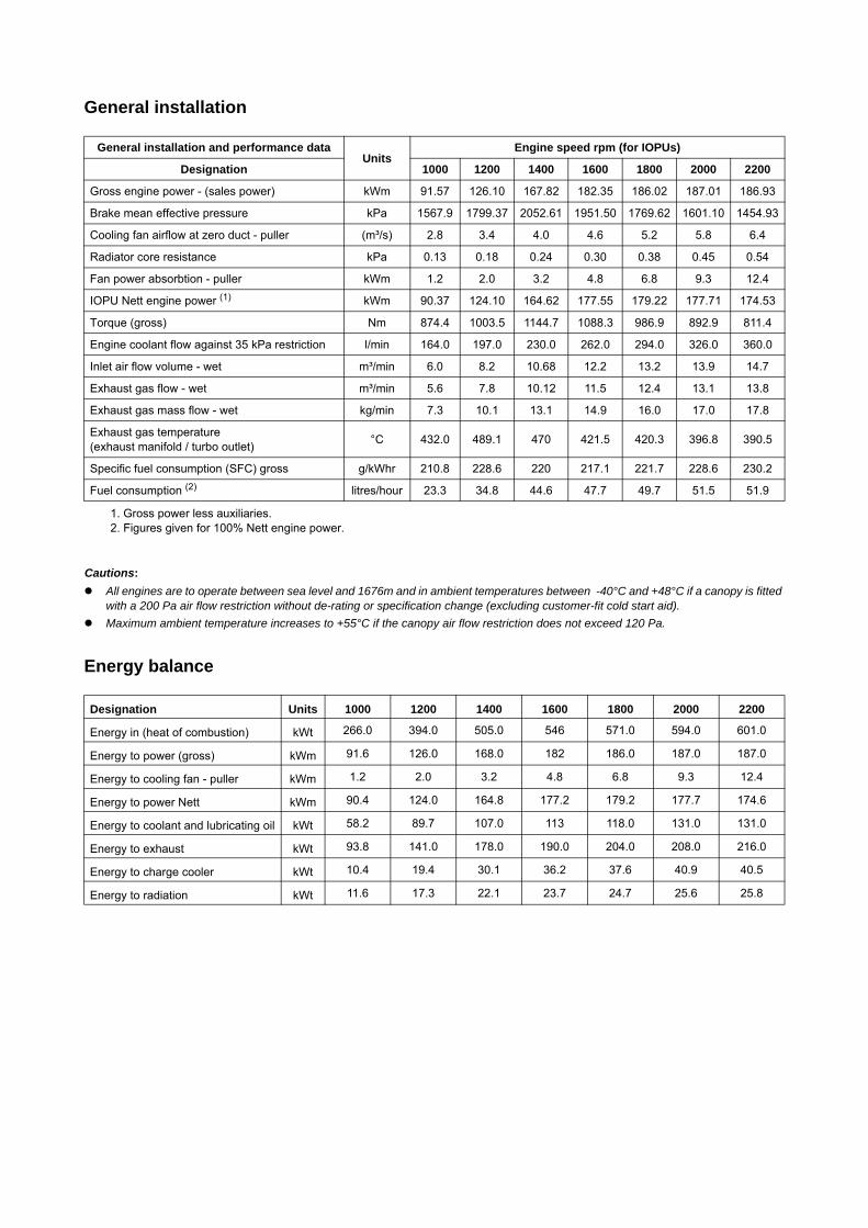
186 kW @ 2200 rpm - left side view
BR
EATH
ER F
ILTE
R E
LEM
ENT
REM
OVA
L20
4.6
365
477.5
3.5
591.
887
7.6
339
174.5
FUEL
IN14
4.9
TO 18 REAR MOUNTING HOLES115.1
DIPSTICK499.6
19.7
535.5
OVERALL1902
234.
9
614
135.6
BR
EATH
ER57
5.4
1281.5
306
OIL FILLER817.6
OVERALL ( WITHOUT AIR CLEANER)1504
135
349.8
69.5
241.6
BTR
Y TE
RM
. 66
.5
RETURN TO TANK1330.9
/ 00BL51498_GA
LUB OIL DRAIN PLUGON SUMP
BATTERY TERMINAL1/2-13 UNC-2A
EARTH TERMINAL1/2-13 UNC-2A
Y Y
X
X
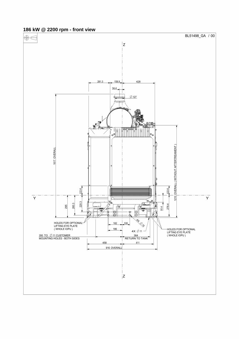
186 kW @ 2200 rpm - front view
127
OVERALL916
186
411
122.
6
122.
6
34.4
278.
4
OVE
RAL
L16
17
281.3 158.9 428
182 1004X
19
458
220.
3
260.
3
295
TO 11 CUSTOMER MOUNTING HOLES - BOTH SIDES350
OVE
RAL
L ( W
ITH
OU
T AF
TER
TREA
MEN
T )
1210
RETURN TO TANK364
91.4
/ 00BL51498_GA
4X 11
HOLES FOR OPTIONALLIFTING EYE PLATE ( WHOLE IOPU ) HOLES FOR OPTIONAL
LIFTING EYE PLATE ( WHOLE IOPU )
Z
Z
Y Y
186 kW @ 2200 rpm - right side view
REM
OVA
L20
1134
.4
524.9
250
LEFT & RIGHT
THROUGH PROFILE
35
405
ALTERNATOR683.6
TO 11 LEFT & RIGHTCUSTOMER MOUNTING HOLES 87.9
TO 11 LEFT & RIGHTCUSTOMER MOUNTING HOLES
808.9
385
98
TO 19 FRONT MOUNTING HOLES
1277.9
OIL
SAM
PLIN
G V
ALVE
34.4
906.
8
RIGHT DRAIN PLUGDIMENSIONS OF PLUG ON SUMP205
234.
9
65.9
915.
3
812.2
/ 00BL51498_GA
OIL SAMPLING VALVETAPPING-PLUGGEDM10 X 1
X
X
Y Y
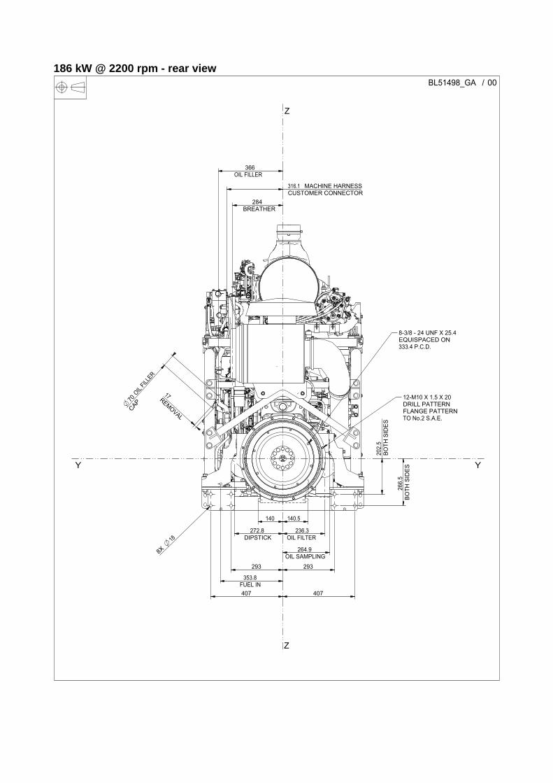
186 kW @ 2200 rpm - rear view
REMOVAL
17BO
TH S
IDES
202.
5
BOTH
SID
ES26
6.5
293
407
293
407
8X
18 DIPSTICK272.8
MACHINE HARNESSCUSTOMER CONNECTOR316.1
140 140.5
FUEL IN353.8
OIL SAMPLING264.9
OIL FILTER236.3
BREATHER284
OIL
FILLE
R
CAP70
OIL FILLER366
/ 00BL51498_GA
12-M10 X 1.5 X 20 DRILL PATTERN FLANGE PATTERN TO No.2 S.A.E.
8-3/8 - 24 UNF X 25.4 EQUISPACED ON 333.4 P.C.D.
Z
Z
Y Y
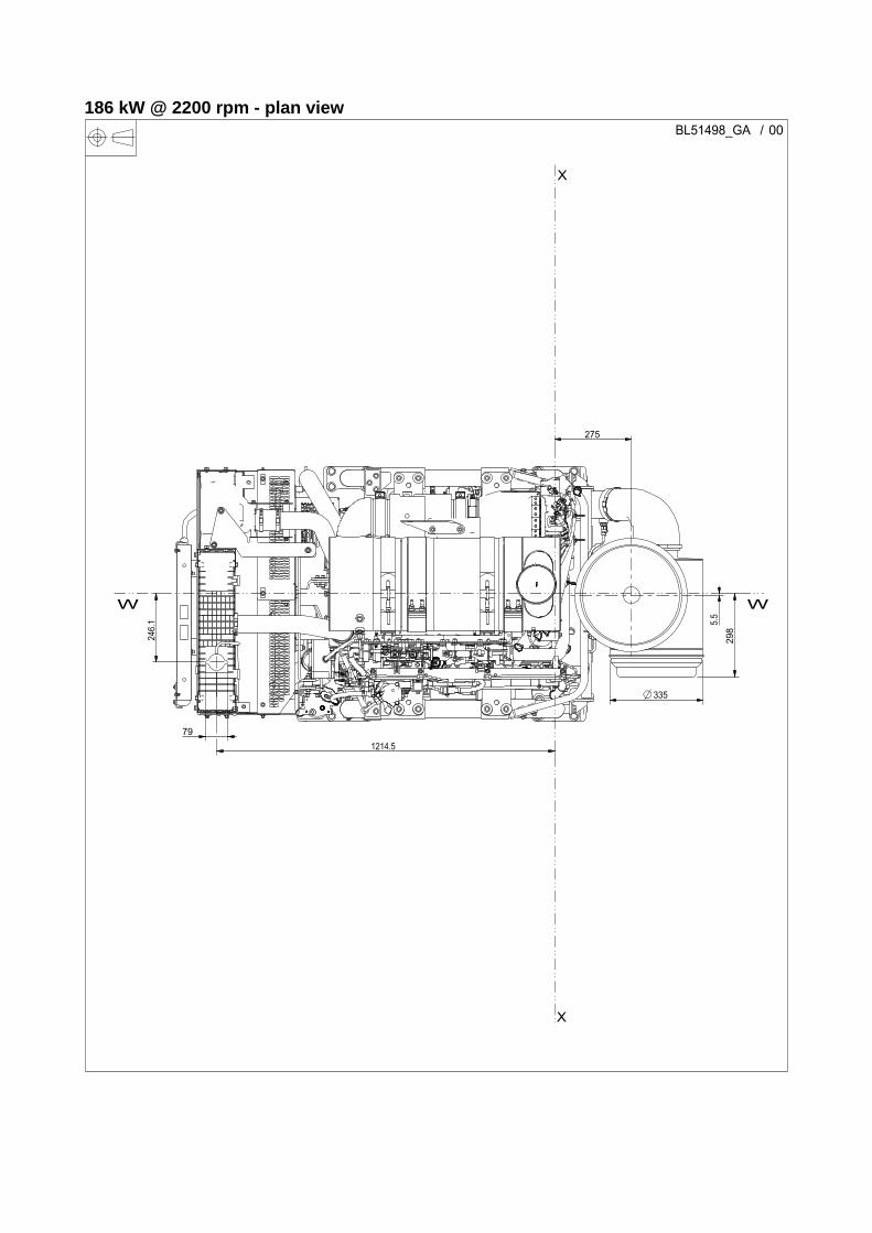
186 kW @ 2200 rpm - plan view
298
5.5
1214.5
275
79
335
246.
1
/ 00BL51498_GA
WW
X
X
Cooling system
Cooling packOverall weight (wet). ... ... ... ... ... ... ... ... ... ... ... ... ... ... .101.7 kgOverall face area . ... ... ... ... ... ... ... ... ... ... ... ... ... ... ...0.6646 m²Width ... ... ... ... ... ... ... ... ... ... ... ... ... ... ... ... ... ... ... ...875.8 mmHeight .. ... ... ... ... ... ... ... ... ... ... ... ... ... ... ... ... ... ... .1088.5 mm
RadiatorMax. load on rad assembly from stone guard mounts. ... ... .2.8 kgFace area ... ... ... ... ... ... ... ... ... ... ... ... ... ... ... ... ... ... .0.444 m²Number of rows .. ... ... ... ... ... ... ... ... ... ... ... ... ... ... ... ... ... ...57 Matrix density . ... ... ... ... ... ... ... ... ... ... ... ... ... ... ... .10 fins/inchWidth of matrix. ... ... ... ... ... ... ... ... ... ... ... ... ... ... ... ...555.0 mmHeight of matrix ... ... ... ... ... ... ... ... ... ... ... ... ... ... ... ...800.0 mmPressure cap setting ... ... ... ... ... ... ... ... ... ... ... ... ... ... ... 1.0 bar
Charge coolerFace area ... ... ... ... ... ... ... ... ... ... ... ... ... ... ... ... ... ... .0.203 m²Number of rows .. ... ... ... ... ... ... ... ... ... ... ... ... ... ... ... ... ... ... .2 Matrix density . ... ... ... ... ... ... ... ... ... ... ... ... ... ... ... .13 fins/inchWidth of matrix. ... ... ... ... ... ... ... ... ... ... ... ... ... ... ... ...257.8 mmHeight of matrix ... ... ... ... ... ... ... ... ... ... ... ... ... ... ... ...789.0 mm
FanType. ... ... ... ... ... ... ... ... ... ... ... ... ... ... ... ... ... ... ... ... ... ..Puller Diameter .. ... ... ... ... ... ... ... ... ... ... ... ... ... ... ... ... ... ...724.0 mmDrive ratio ... ... ... ... ... ... ... ... ... ... ... ... ... ... ... ... ... ... ... ... ..1:1 Number of blades ... ... ... ... ... ... ... ... ... ... ... ... ... ... ... ... ... ..7.0 Material ... ... ... ... ... ... ... ... ... ... ... ... ... ... ... ... ... ... ..Composite
Coolant Total system capacity .. ... ... ... ... ... ... ... ... ... ... ... ... . 24.25 litresBare engine capacity ... ... ... ... ... ... ... ... ... ... ... ... ... . 12.25 litresMaximum top tank temperature... ... ... ... ... ... ... ... ... ... ... .108°CThermostat operation range ... ... ... ... ... ... ... ... ... ... ... 82 - 94°CRecommended coolantThe following two coolants are used in Perkins diesel engines:Preferred - Perkins ELCAcceptable - A commercial heavy-duty antifreeze that meets "ASTM D6210 " specifications.1 The 1200 series industrial engines must be operated with a 1:1 mixture of water and glycol. This concentration allows the NOx reduction system to operate correctly at high ambient temperatures.2 Do not use a commercial coolant/antifreeze that only meets the ASTM D3306 specification. This type of coolant/antifreeze is made for light automotive applications.
Maximum additional restriction (Duct allowance) to cooling airflow and resultant Min. airflow
Electrical system
Engine stop method.. ... ... ... ... ... ... ... ... ... ... ... .ECM controlled
Pulle
r
Am
bien
t cle
aran
ce
Duc
t allo
wan
ce
Coo
ling
fan
airf
low
Rad
iato
r cor
e re
sist
ance
Enginespeedrpm
°C kPa m³/min kPa
1800 55 120 4.62 553
2200 55 120 5.82 791
1800 55 200 4.27 609
2200 55 200 5.42 871
Alternator model Unit Remy 13SI
Remy 13SI
Alternator voltage Volts 12 24
Alternator output Amps 120 80
Starter model (+SAE ?) Unit Iskra AZF
Remy iMT
Denso P5
Starter motor voltage Volts 12 24 12
Starter motor power kW 4.0 8.5 5.0
Number of teeth on flywheel
SAE 1 D0093 156
Number of teeth on flywheel
SAE 2 D0094 134
Number of teeth on flywheel
SAE 3 D0004 126 126 (1)
1. 24V SAE 3 Options only compatible with C0067 LHSStarter.
126
Number of teeth on starter pinion 10 12 13
Minimum cranking speed rpm 100
Starter solenoid - Max. pull-in current @ 0°C Amps 68 2 41
Starter solenoid - Max. hold-in current @ 0°C Amps 20 2 11
Cold start recommendations
Minimum battery cold cranking ampsAir
Temp. oil viscosity limit °C
With glow plugs 12V AZF and P5
bare engine
Without glow plugs 12V AZF bare
engine
With glow plugs 24V IMT bare
engine
Without glow plugs 24V IMT bare
engine
With glow plugs 24V AZF HP bare
engine
Without glow plugs 24V AZF HP bare
engine
-5 15W40 950 15W40 950 15W40 525 15W40 525 15W40 525 15W40 525
-10 15W40 950 15W40 950 15W40 525 15W40 525 15W40 525 15W40 525
-15 15W40 1650 15W40Must use
glow plugs (1)
1. Must use glow plugs
15W40 680 15W40Must use
glow-plugs (1)
15W40 680 15W40Must use
glow-plugs (1)
-20 10W40 1650 10W40Must use
glow-plugs (1)
10W40 680 10W40Must use
glow-plugs (1)
10W40 680 10W40Must use
glow-plugs (1)
-25 5W30 1900 5W30Must use
glow-plugs (1)
5W30 750 5W30Must use
glow-plugs (1)
5W30 680 5W30Must use
glow-plugs (1)
Max. battery CCA.
2400 2400 1400 1400 1200 1200
Exhaust system aftertreatment Fuel injection system
Aftertreatment system type.. ... ... ... ... ... DOC and DPF with ARDType of regeneration (high/low temperature) .. ... ... ... ... ... ... HighAftertreatment height ... ... ... ... ... ... ... ... ... ... ... ... ... ...643.9 mmAftertreatment length ... ... ... ... ... ... ... ... ... ... ... ... ... ...918.7 mmAftertreatment width ... ... ... ... ... ... ... ... ... ... ... ... ... ...714.4 mmAftertreatment weight .. ... ... ... ... ... ... ... ... ... ... ... ... ... 134.0 KgOutlet orientation when viewed from rear of engine ... ... ... .. 90.0°Aftertreatment skin temperature .. ... ... ... ... ... ... ... ... ... ..250.0°CMax. Temp. for electronic components on aftertreatment ..120.0°CMax. Temp. for external electronic components for aftertreatment (Soot Sensor Box) ... ... ... ... ... ... ... ... ... ... 85.0°CTypical Max. temperature exhaust out ... ... ... ... ... ... ... ..650.0°CMax. system back pressure limit forHP 175 - 300 / 130 - 224 kW... ... ... ... ... ... ... ... ... ... ... .35.0 kpaAftertreatment exhaust outlet connection ... ... ... ... ... ...127.0 mmAftertreatment exhaust outlet connection load limit. ... ... ... 60 NmAttenuation of the DPF ... ... ... ... ... ... ... ... ... ... ... ... ..25.0 dB(A)Ash service .. ... ... ... ... ... ... ... ... ... ... ... ... ... ... ... ..5000.0 hoursMaximum back pressure for customer installed pipe work.. 60 kPa
Induction system
Maximum air intake restrictionClean filter ... ... ... ... ... ... ... ... ... ... ... ... ... ... ... ... ... ... ...5.0 kPaDirty filter . ... ... ... ... ... ... ... ... ... ... ... ... ... ... ... ... ... ... ...8.0 kPaInduction indicator setting ... ... ... ... ... ... ... ... ... ... ... ... ...8.0 kPaAir filter type. ... ... ... ... ... ... ... ... ... ... ... ... ... ... ... ... ... ...125 pm
Fuel pump type / model ... ... ... ... ... ... ... ... ... ... ... ...Denso HP4Injection system ... ... ... ... ... ... ... ... ... ... ... ... ... ... ... ..ElectronicInjector type .. ... ... ... ... ... ... ... ... ... ... ... ... ... ... ... ..common railInjection pressure.. ... ... ... ... ... ... ... ... ... ... ... ... ... ... ... 200 MPa
Fuel feedFuel lift pump type. ... ... ... ... ... ... ... ... ... ... ... ... ... ... ... . GerotorMax. fuel supply restriction at primary filter... ... ... ... ... ... . -30 kPaMax. fuel return restriction at low idle ... ... ... ... ... ... ... ... .. 20 kPaMax. fuel return flow.. ... ... ... ... ... ... ... ... ... ... ... ... ... 2.5 m³/minMax. fuel flow through inlet connection. ... ... ... ... ... ... ... 3.7 l/minMax. lift pump delivery flow rate ... ... ... ... ... ... ... ... ... ... 3.7 l/minMax. pump delivery pressure ... ... ... ... ... ... ... ... ... ... 8500.0 kPaMax. suction head at fuel pump inlet regulated to Approx. 50 KPaMax. static pressure head. ... ... ... ... ... ... ... ... ... ... ... ... .. 20 kPaMax. fuel temperature at lift pump inlet. ... ... ... ... ... ... ... ... . 80°CMax. fuel filter service interval... ... ... ... ... ... ... ... ... ... ... . 500 hrs
Fuel specification
BS2869 Class 2 (off highway, gas oil); DIN EN590 DERV (Class A to F and 0 to 4)Density . ... ... ... ... ... ... ... ... ... ... ... . 0.840 - 0.865 (kg/l @ 15°C)Viscosity ... ... ... ... ... ... ... ... ... ... ... ... 2.0 - 3.2 (mm²/s @ 40°C)Sulphur content ... ... ... ... ... ... ... ... ... 0.0007 - 0.0015 (% mass)Cetane № . ... ... ... ... ... ... ... ... ... ... ... ... ... ... ... ... ... ... ... 40 - 0
Fuel consumption (SFC)
Load
1000rpm
1200rpm
1400rpm
1600rpm
1800rpm
2000rpm
2200rpm
g/kW
hr
l/hr
g/kW
hr
l/hr
g/kW
hr
l/hr
g/kW
hr
l/hr
g/kW
hr
l/hr
g/kW
hr
l/hr
g/kW
hr
l/hr
25%50%75%
100% 210.8 34.8 228.6 34.8 220 44.6 217.1 47.7 221.7 49.7 228.5 51.5 230.1 51.87
1200 Series 186 kW @ 2200 rpm
Per
kins
Eng
ines
Com
pany
Lim
ited.
Lubrication system
Total system capacity (to include filter, rail and cooler) ..17.9 LitresMaximum sump capacity . ... ... ... ... ... ... ... ... ... ... ... ..16.0 LitresMinimum sump capacity .. ... ... ... ... ... ... ... ... ... ... ... ..13.0 LitresMaximum oil temperature continuos operation ... ... ... ... ... 125°CMaximum oil temperature intermittent operation.. ... ... ... ... 135°C
Lubricating oil pressureAt rated speed.. ... ... ... ... ... ... ... ... ... ... ... ... ... .. 400 to 520 kPaMinimum .. ... ... ... ... ... ... ... ... ... ... ... ... ... ... ... ... ... .. 220.0 kPaOil relief valves opens at.. ... ... ... ... ... ... ... ... ... ... ... ... . 520 kPaSump drain plug tapping size or hose connection size ... ... ... ... ... ... ... ... ...3/4 UNF STOR portOil pump speed/drive method. ... . Gerotor (gear driven off crankshaft)Lubricating oil flow at rated speed ... ... ... ... ... ... ... ..60 litres/min.Lubricating oil pressure at rated speed ... ... ... ... .. 400 to 520 kPaOil consumption at full load rated speed . ... ... ... ... 0.08 % of fuel
Recommended SAE viscosity
A multigrade oil conforming to API-CJ4 (ACEA-E9) must be used.
Normal operating angles
Front and rear .. ... ... ... ... ... ... ... ... ... ... ... ... ... ... ... ... ... ... .25°Side.. ... ... ... ... ... ... ... ... ... ... ... ... ... ... ... ... ... ... ... ... ... ... .25°
PTO capabilities
Note: Refer to “Applications and Installation Manual” for “PTO approval requirements”.
Mountings
Note: Refer to “Applications and Installation Manual” for “Bending Moment approval requirements”.
Viscostiy grade
-50 -40 -30 -20 -10 0 10 20 30 40 50 60
0W-20
0W-30
0W-40
5W-30
5W-40
10W-30
10W-40
15W-40
Ambient temperature °C
Standard Heavy duty
Flange typeVarious refer to
ESM
SAE “B” 13 tooth spline
Torque capability intermittent (Nm) 142 210
Torque capability continuous (Nm) 99 147
Max. bending moment at flange (Nm) 0 15
Maximum static bending moment at rear face of block Nm 1130
Maximum permissible overhung load on the flywheel Nm See Polar diagram
chapter 6 of the ESM
Dynamic vertical BM
Dynamic lateral BM
Max. bending moment at rear of flywheel housing - SAE 3 Nm ±3000 ±1700
Max. bending moment at rear of flywheel housing - SAE 2 Nm ±5600 ±2800
Max. bending moment at rear of flywheel housing - SAE 1 Nm ±8200 ±5750
All information in the document is substantially correct at the time of printing but may be subsequently altered by the company.
Distributed by
Pub
licat
ion
No.
TP
D17
80, I
SS
UE 2
. Dec
embe
r 201
1. ©
Perkins Engines Company LimitedPeterborough PE1 5NA United KingdomTelephone +44 (0) 1733 583000Fax +44 (0) 1733 582240www.perkins.com


![TU UZ A - Digital Library/67531/metadc... · iopU]QWERT YUIOP{asd fghjkl;\AS DFGHJKL:|` zxcvbnm,./} ~ZXCVBNM The UNEP Magazine For Youth Vol1 No3 TU UZ A food issues and problems](https://img.pdfslide.us/doc/110x75/5e29533b03996756f14ba59e/tu-uz-a-digital-library-67531metadc-iopuqwert-yuiopasd-fghjklas-dfghjkl.jpg)