Embed Size (px)
Citation preview
© 2007 Microchip Technology Incorporated. All Rights Reserved. 11085 MCW Slide 1
11085 MCW
dsPIC® DSCMotor Control Workshop
© 2007 Microchip Technology Incorporated. All Rights Reserved. 11085 MCW Slide 2
Class Objectives
After this class you should…– Know the Operation of the dsPIC® DSC Motor
Control Peripherals– Know the Fundamentals of a Brushless DC
Motor– Know the Different Methods to Control a
Brushless DC Motor– Know How to Use the Motor Control GUI
© 2007 Microchip Technology Incorporated. All Rights Reserved. 11085 MCW Slide 3
Workshop Agenda
dsPIC® DSC OverviewBLDC Motor Control TheoryBLDC Motor Control AlgorithmsLabs
© 2007 Microchip Technology Incorporated. All Rights Reserved. 11085 MCW Slide 4
Agenda In-depth
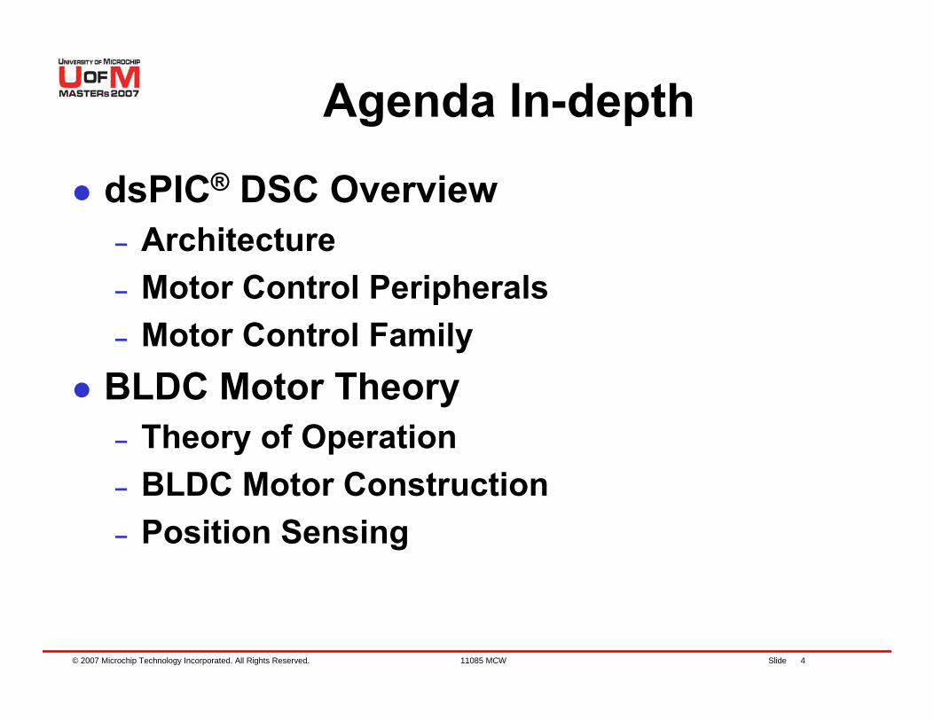
dsPIC® DSC Overview– Architecture– Motor Control Peripherals – Motor Control Family
BLDC Motor Theory– Theory of Operation– BLDC Motor Construction– Position Sensing
© 2007 Microchip Technology Incorporated. All Rights Reserved. 11085 MCW Slide 5
Agenda In-depth
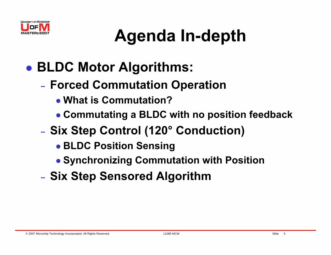
BLDC Motor Algorithms:– Forced Commutation Operation
What is Commutation?Commutating a BLDC with no position feedback
– Six Step Control (120° Conduction)BLDC Position SensingSynchronizing Commutation with Position
– Six Step Sensored Algorithm
© 2007 Microchip Technology Incorporated. All Rights Reserved. 11085 MCW Slide 6
Agenda In-depth
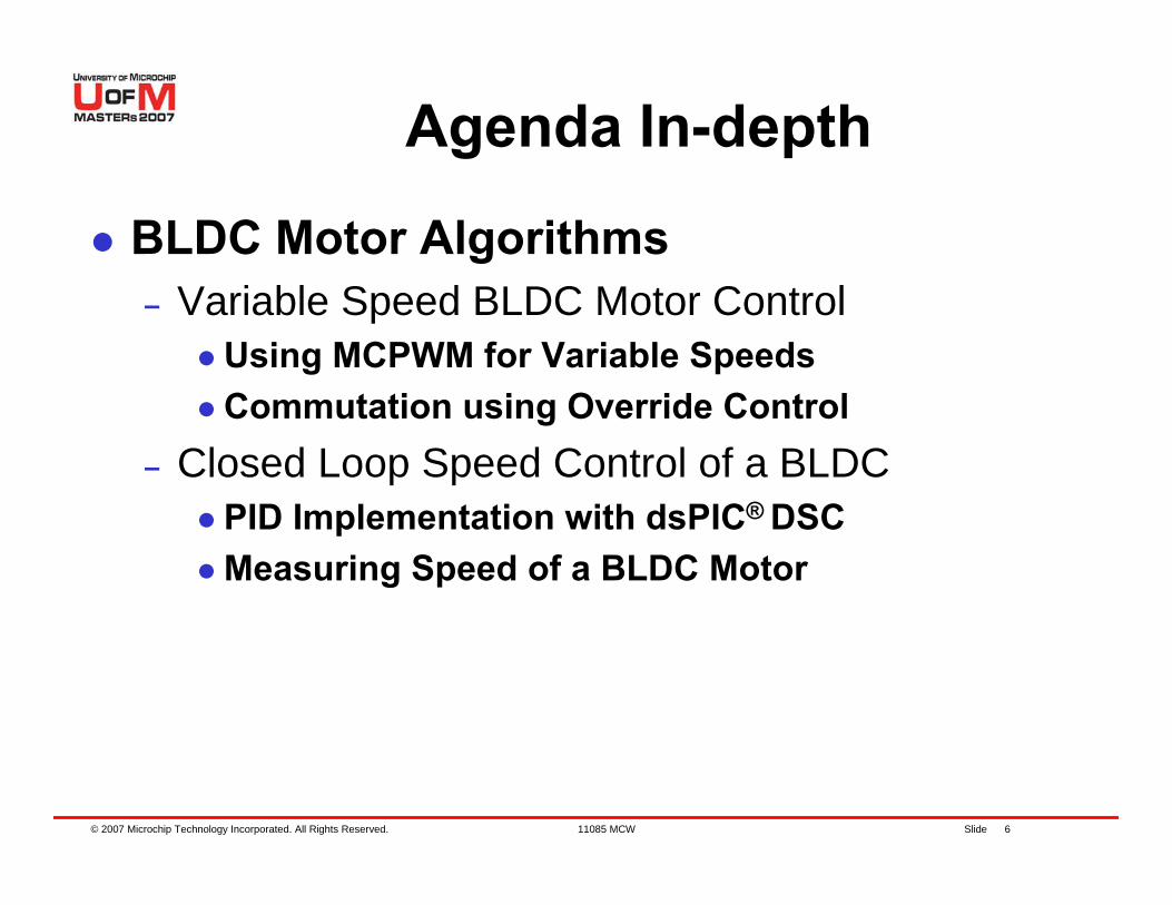
BLDC Motor Algorithms– Variable Speed BLDC Motor Control
Using MCPWM for Variable SpeedsCommutation using Override Control
– Closed Loop Speed Control of a BLDCPID Implementation with dsPIC® DSCMeasuring Speed of a BLDC Motor
© 2007 Microchip Technology Incorporated. All Rights Reserved. 11085 MCW Slide 7
Agenda In-depth
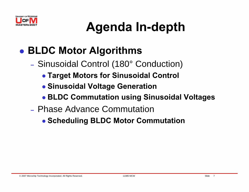
BLDC Motor Algorithms– Sinusoidal Control (180° Conduction)
Target Motors for Sinusoidal ControlSinusoidal Voltage GenerationBLDC Commutation using Sinusoidal Voltages
– Phase Advance CommutationScheduling BLDC Motor Commutation
© 2007 Microchip Technology Incorporated. All Rights Reserved. 11085 MCW Slide 8
Agenda In-depth
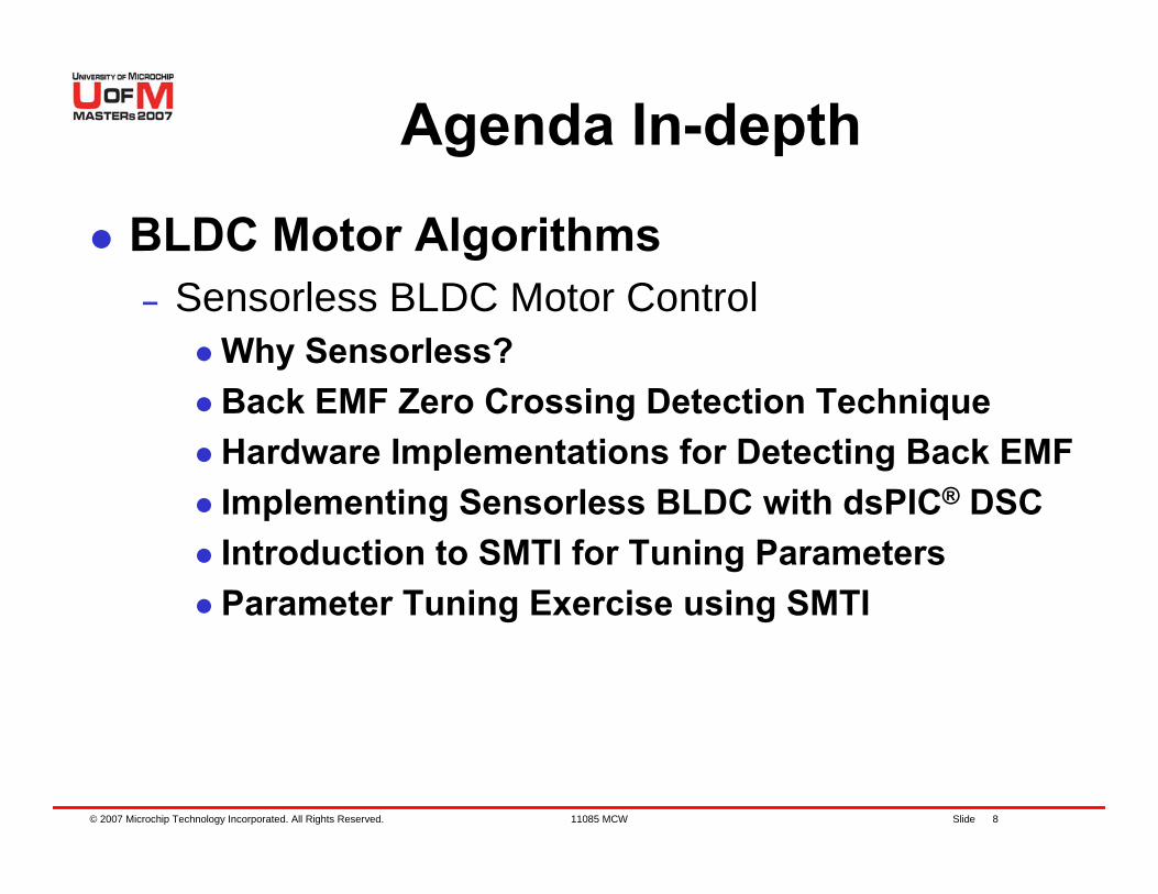
BLDC Motor Algorithms– Sensorless BLDC Motor Control
Why Sensorless?Back EMF Zero Crossing Detection TechniqueHardware Implementations for Detecting Back EMFImplementing Sensorless BLDC with dsPIC® DSCIntroduction to SMTI for Tuning ParametersParameter Tuning Exercise using SMTI
© 2007 Microchip Technology Incorporated. All Rights Reserved. 11085 MCW Slide 9
Agenda In-depth
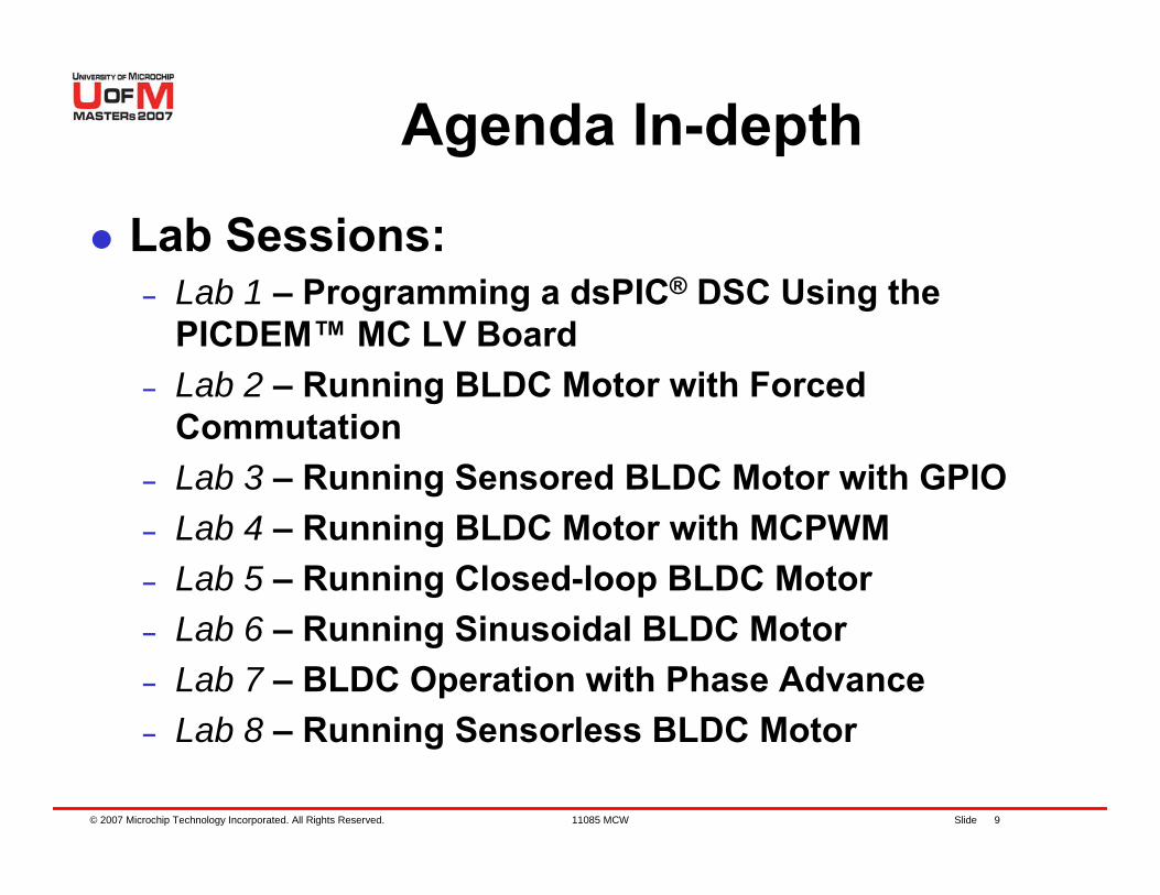
Lab Sessions:– Lab 1 – Programming a dsPIC® DSC Using the
PICDEM™ MC LV Board– Lab 2 – Running BLDC Motor with Forced
Commutation– Lab 3 – Running Sensored BLDC Motor with GPIO – Lab 4 – Running BLDC Motor with MCPWM– Lab 5 – Running Closed-loop BLDC Motor– Lab 6 – Running Sinusoidal BLDC Motor– Lab 7 – BLDC Operation with Phase Advance– Lab 8 – Running Sensorless BLDC Motor
© 2007 Microchip Technology Incorporated. All Rights Reserved. 11085 MCW Slide 10
dsPIC® DSC Overview
© 2007 Microchip Technology Incorporated. All Rights Reserved. 11085 MCW Slide 11
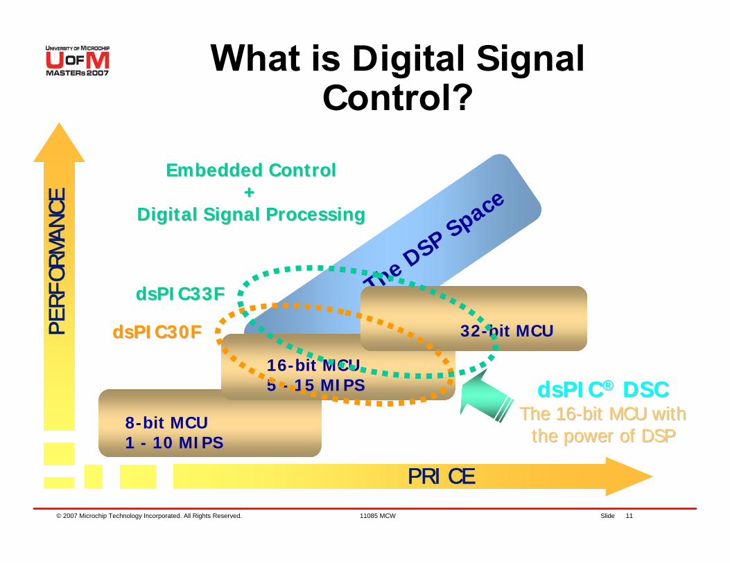
The DSP Space
8-bit MCU1 - 10 MIPS
16-bit MCU5 - 15 MIPS
32-bit MCU
PRICE
PE
RF
OR
MA
NC
EWhat is Digital Signal
Control?
Embedded ControlEmbedded Control++
Digital Signal ProcessingDigital Signal Processing
dsPICdsPIC®® DSCDSCThe 16The 16--bit MCU with bit MCU with
the power of DSPthe power of DSP
dsPIC30FdsPIC30F
dsPIC33FdsPIC33F
© 2007 Microchip Technology Incorporated. All Rights Reserved. 11085 MCW Slide 12
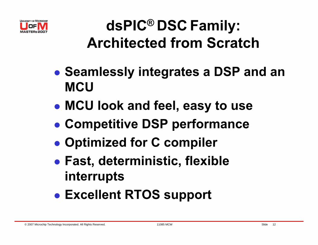
dsPIC® DSC Family: Architected from Scratch
Seamlessly integrates a DSP and an MCUMCU look and feel, easy to useCompetitive DSP performanceOptimized for C compilerFast, deterministic, flexible interruptsExcellent RTOS support
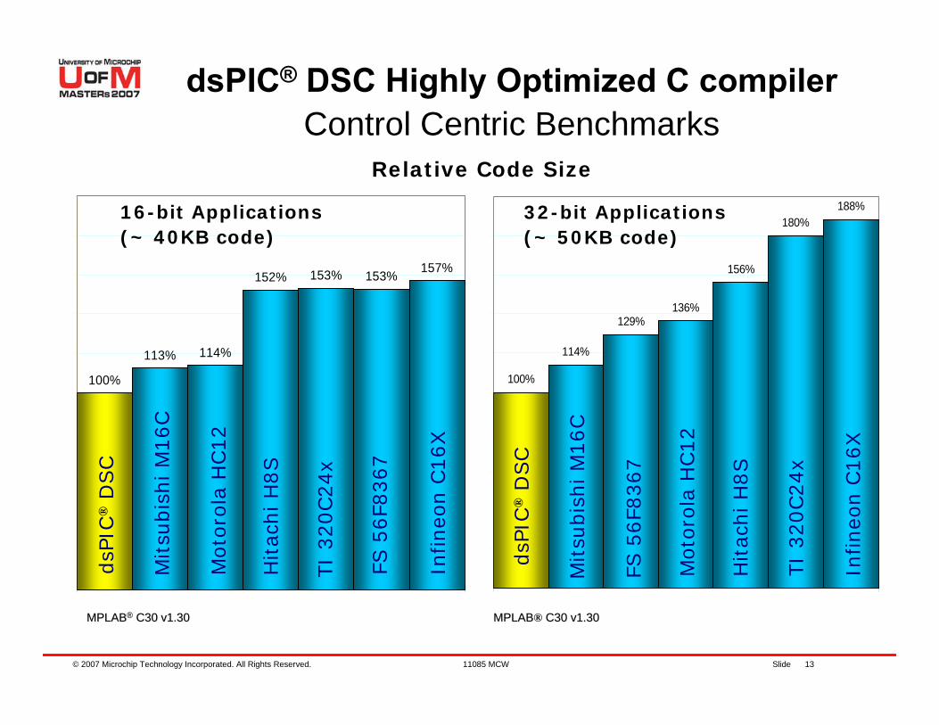
© 2007 Microchip Technology Incorporated. All Rights Reserved. 11085 MCW Slide 13
100%
114%
129%136%
156%
180%188%
100%
113% 114%
152% 153% 153% 157%
dsPIC® DSC Highly Optimized C compilerControl Centric Benchmarks
16-bit Applications(~ 40KB code)
32-bit Applications(~ 50KB code)
Relative Code Size
MPLABMPLAB®® C30 v1.30C30 v1.30 MPLABMPLAB® C30 v1.30C30 v1.30
dsP
IC®
DSC
dsP
IC®
DSC
Mitsu
bis
hi M
16C
Mitsu
bis
hi M
16C
Moto
rola
HC12
Moto
rola
HC12
Hitac
hi H
8S
Hitac
hi H
8S
TI
320C24x
TI
320C24x
Infineo
n C
16X
Infineo
n C
16X
FS 5
6F8
367
FS 5
6F8
367
© 2007 Microchip Technology Incorporated. All Rights Reserved. 11085 MCW Slide 14
dsPIC® DSC Architecture Summary
© 2007 Microchip Technology Incorporated. All Rights Reserved. 11085 MCW Slide 15
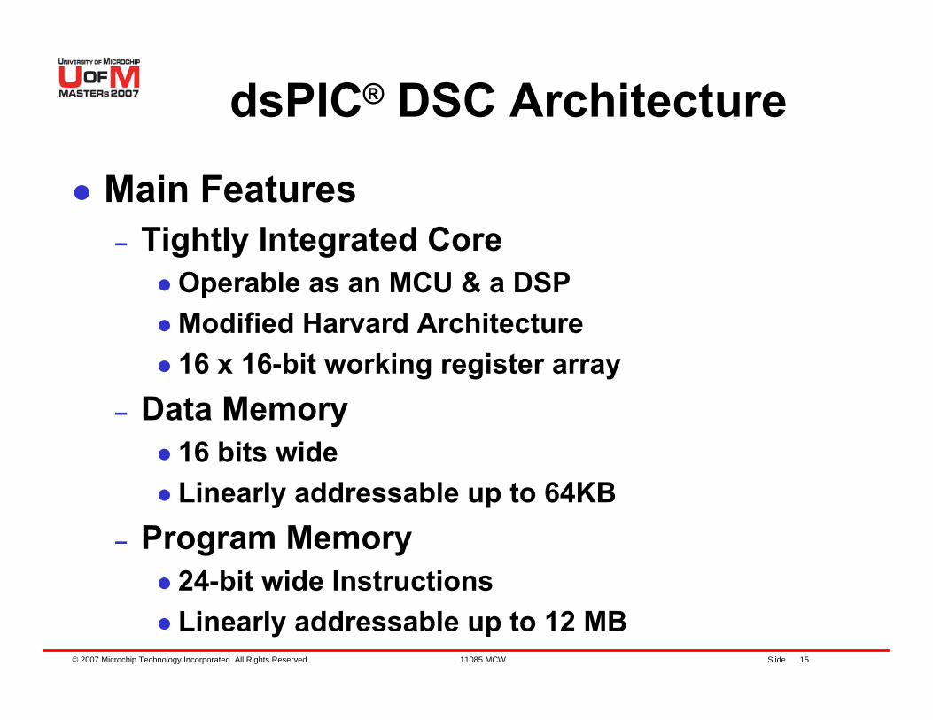
dsPIC® DSC Architecture
Main Features– Tightly Integrated Core
Operable as an MCU & a DSPModified Harvard Architecture16 x 16-bit working register array
– Data Memory16 bits wideLinearly addressable up to 64KB
– Program Memory24-bit wide InstructionsLinearly addressable up to 12 MB
© 2007 Microchip Technology Incorporated. All Rights Reserved. 11085 MCW Slide 16
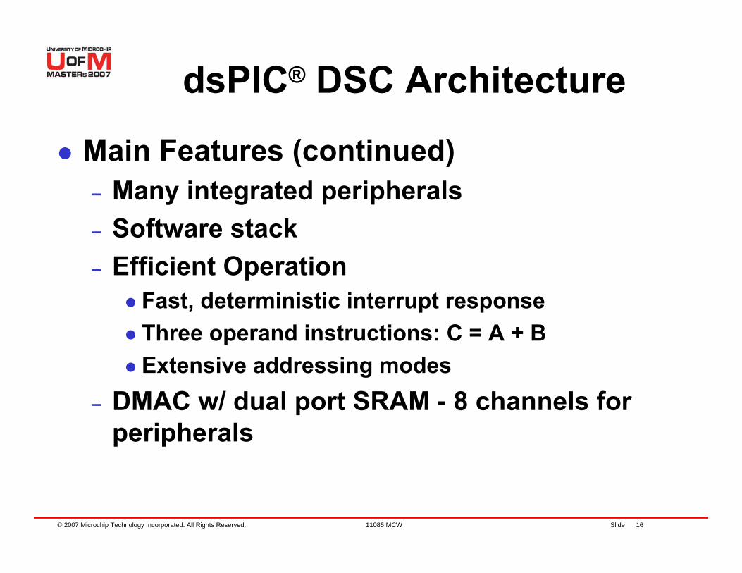
dsPIC® DSC Architecture
Main Features (continued)– Many integrated peripherals– Software stack– Efficient Operation
Fast, deterministic interrupt responseThree operand instructions: C = A + BExtensive addressing modes
– DMAC w/ dual port SRAM - 8 channels for peripherals
© 2007 Microchip Technology Incorporated. All Rights Reserved. 11085 MCW Slide 17
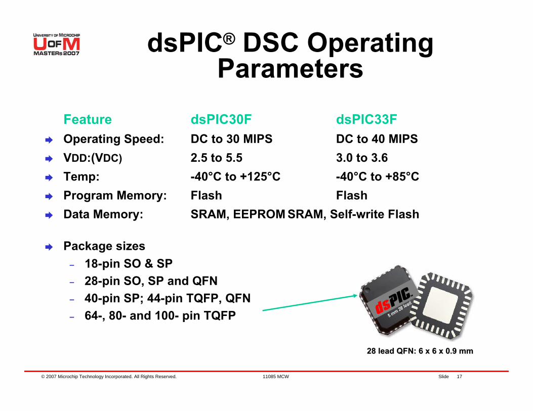
dsPIC® DSC Operating Parameters
Feature dsPIC30F dsPIC33FOperating Speed: DC to 30 MIPS DC to 40 MIPSVDD:(VDC) 2.5 to 5.5 3.0 to 3.6Temp: -40°C to +125°C -40°C to +85°CProgram Memory: Flash FlashData Memory: SRAM, EEPROM SRAM, Self-write Flash
Package sizes– 18-pin SO & SP – 28-pin SO, SP and QFN– 40-pin SP; 44-pin TQFP, QFN– 64-, 80- and 100- pin TQFP D
S
28 lead QFN: 6 x 6 x 0.9 mm28 lead QFN: 6 x 6 x 0.9 mm
© 2007 Microchip Technology Incorporated. All Rights Reserved. 11085 MCW Slide 18
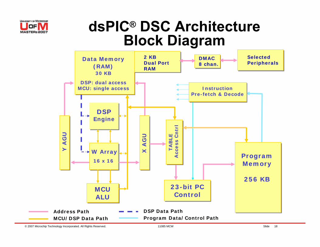
dsPIC® DSC Architecture Block Diagram
W Array
16 x 16
23-bit PCControl
DSPEngine
MCU ALU
Data Memory(RAM)30 KB
DSP: dual accessMCU: single access
X A
GU
Y A
GU
InstructionPre-fetch & Decode
TA
BLE
Acc
ess
Cn
trl
Address PathMCU/DSP Data Path Program Data/Control Path
DSP Data Path
ProgramMemory
256 KB
2 KBDual Port RAM
DMAC8 chan.
Selected Peripherals

© 2007 Microchip Technology Incorporated. All Rights Reserved. 11085 MCW Slide 19
dsPIC® DSC Peripherals Overview
© 2007 Microchip Technology Incorporated. All Rights Reserved. 11085 MCW Slide 20
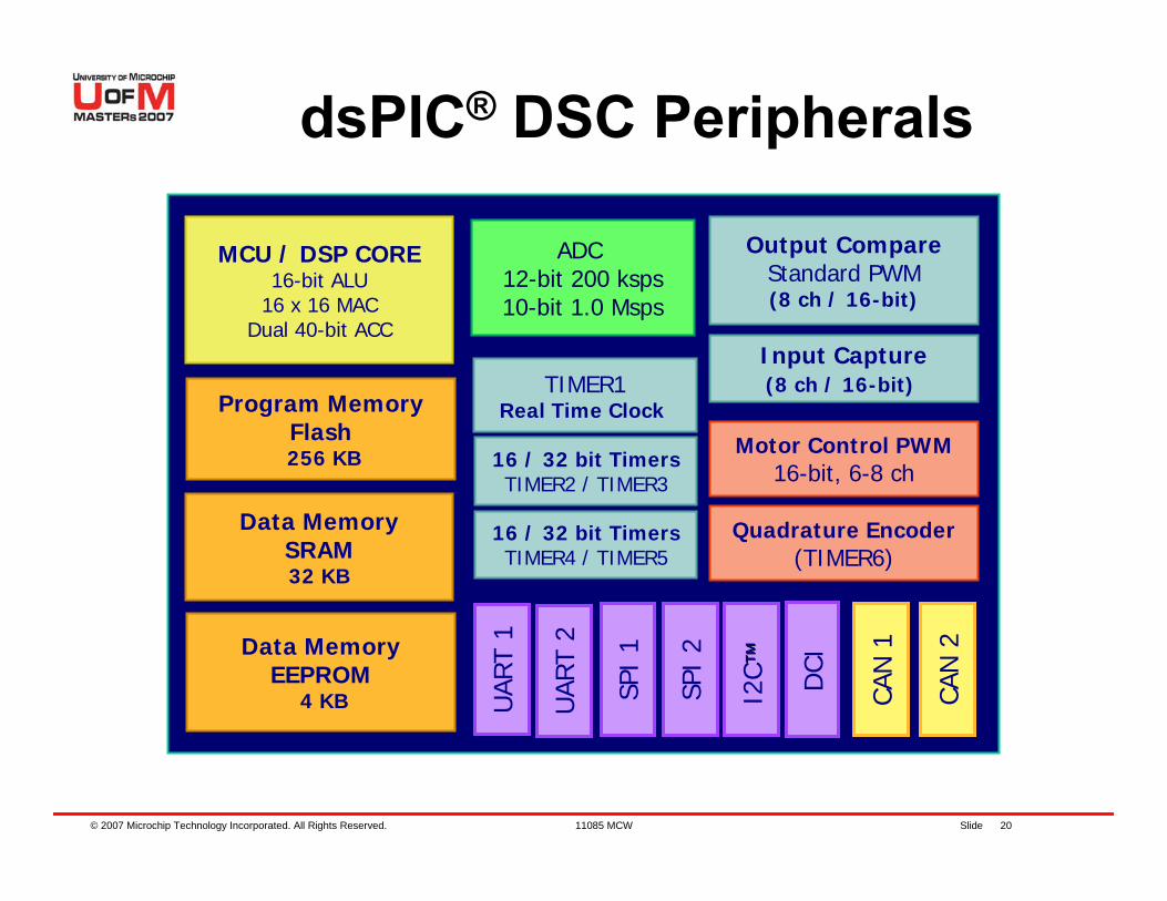
dsPIC® DSC Peripherals
MCU / DSP CORE16-bit ALU
16 x 16 MACDual 40-bit ACC
Program MemoryFlash256 KB
Data MemorySRAM32 KB
Data MemoryEEPROM
4 KB
TIMER1Real Time Clock
16 / 32 bit TimersTIMER2 / TIMER3
Quadrature Encoder(TIMER6)
Motor Control PWM16-bit, 6-8 ch
Output CompareStandard PWM(8 ch / 16-bit)
Input Capture(8 ch / 16-bit)
UAR
T 1
UAR
T 2
SPI
1
SPI
2
I2C ™™ DCI
CAN
1
CAN
2
ADC 12-bit 200 ksps10-bit 1.0 Msps
16 / 32 bit TimersTIMER4 / TIMER5
© 2007 Microchip Technology Incorporated. All Rights Reserved. 11085 MCW Slide 21
A/D Converter
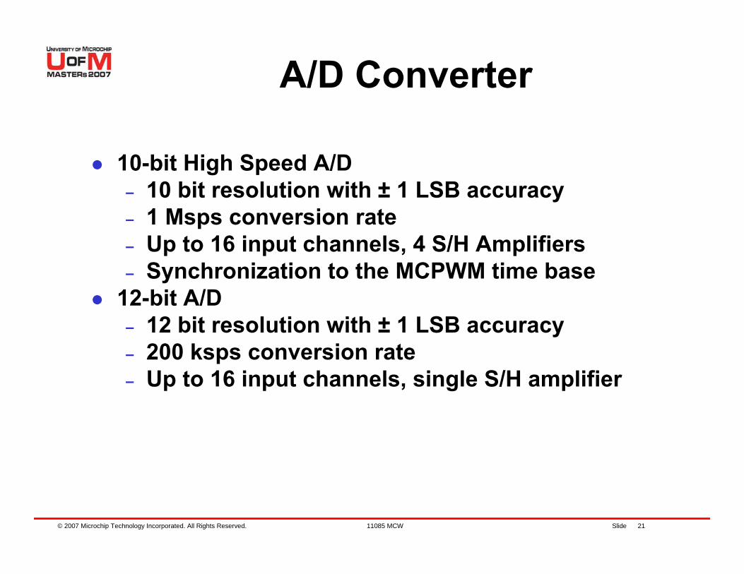
10-bit High Speed A/D– 10 bit resolution with ± 1 LSB accuracy– 1 Msps conversion rate– Up to 16 input channels, 4 S/H Amplifiers– Synchronization to the MCPWM time base
12-bit A/D– 12 bit resolution with ± 1 LSB accuracy– 200 ksps conversion rate– Up to 16 input channels, single S/H amplifier
© 2007 Microchip Technology Incorporated. All Rights Reserved. 11085 MCW Slide 22
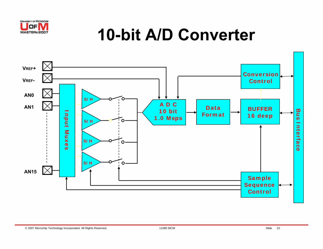
10-bit A/D Converter
VREF+
VREF-
A D C10 bit
1.0 Msps
ConversionControl
Bu
sIn
terfa
ce
BUFFER16 deep
DataFormat
SampleSequenceControl
Inp
ut M
uxes
AN0
AN1S/H
S/H
S/H
S/H
AN15
© 2007 Microchip Technology Incorporated. All Rights Reserved. 11085 MCW Slide 23
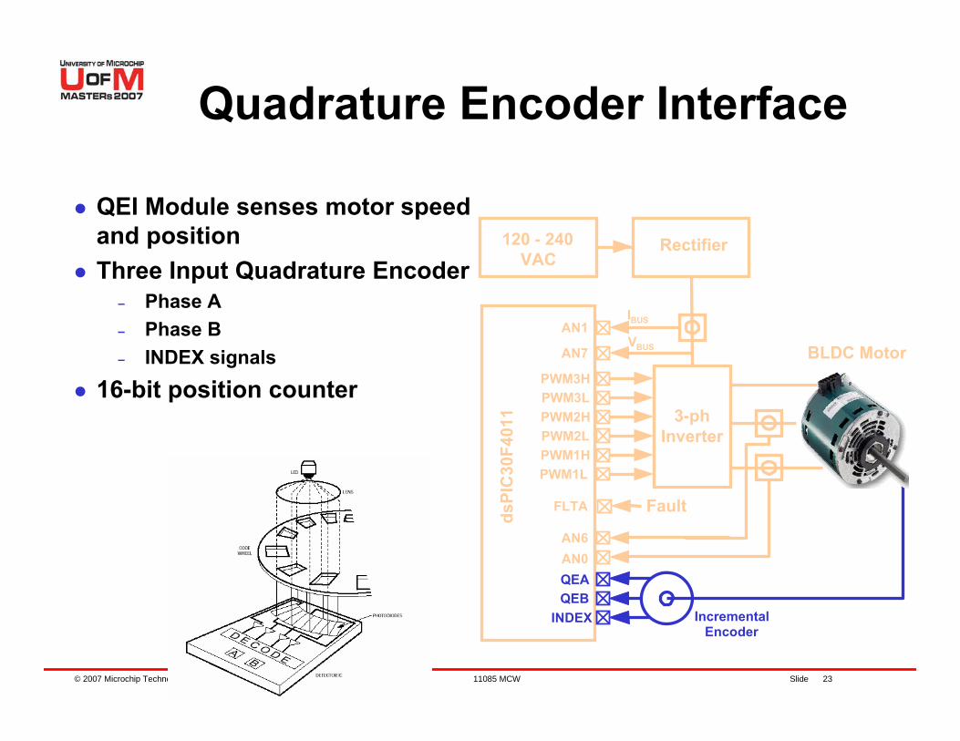
Quadrature Encoder Interface
QEI Module senses motor speed and positionThree Input Quadrature Encoder
– Phase A– Phase B– INDEX signals
16-bit position counter3-ph
Inverter
VBUS
AN6AN0QEAQEB
INDEX
AN7
PWM3HPWM3LPWM2HPWM2LPWM1HPWM1L
FLTA Fault
IBUSAN1
120 - 240VAC
BLDC Motor
IncrementalEncoder
dsPI
C30
F401
1
Rectifier
© 2007 Microchip Technology Incorporated. All Rights Reserved. 11085 MCW Slide 24
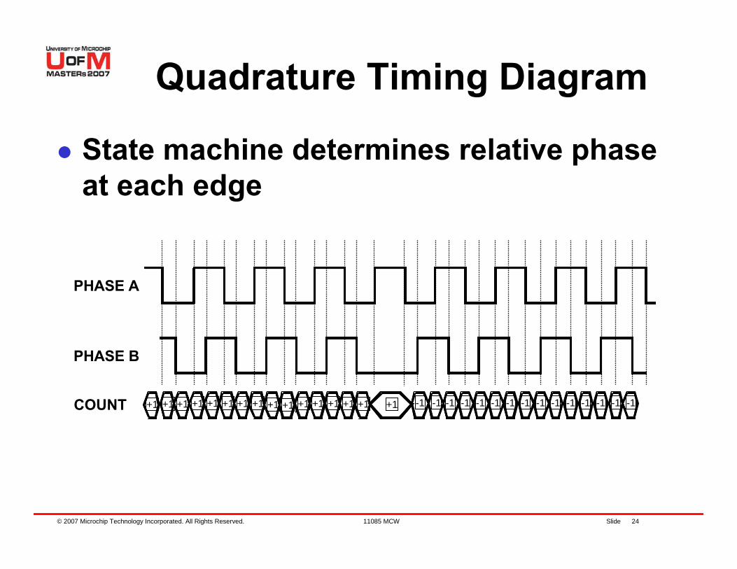
+1 +1+1 +1 +1 +1 +1 +1 +1 +1 +1 +1 +1 +1 +1 +1 -1 -1 -1 -1 -1 -1 -1 -1 -1 -1 -1 -1 -1 -1 -1COUNT
PHASE A
PHASE B
State machine determines relative phase at each edge
Quadrature Timing Diagram
© 2007 Microchip Technology Incorporated. All Rights Reserved. 11085 MCW Slide 25
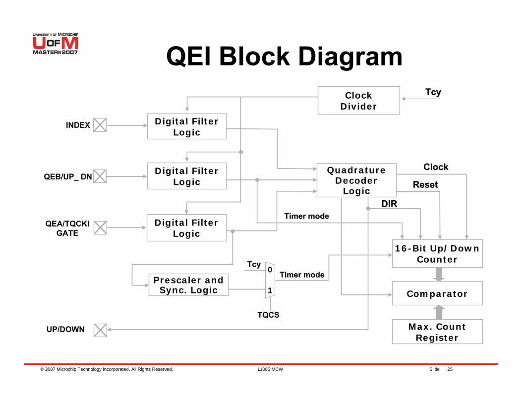
QEI Block DiagramClock
Divider
INDEX
1
0
TQCS
TcyTcy
Digital FilterLogic
Digital FilterLogic
Digital FilterLogic
QEB/UP_ DN
QEA/TQCKIGATE
Prescaler andSync. Logic
TcyTcy
UP/DOWN
16-Bit Up/DownCounter
DIRDIR
QuadratureDecoder
Logic
ClockClock
ResetReset
Max. CountRegister
Timer modeTimer mode
Timer modeTimer mode
Comparator
© 2007 Microchip Technology Incorporated. All Rights Reserved. 11085 MCW Slide 26
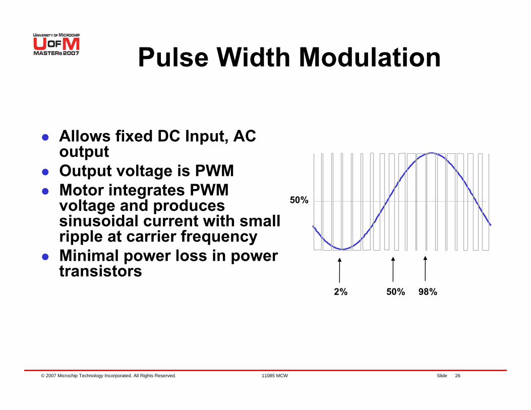
Pulse Width Modulation
Allows fixed DC Input, AC outputOutput voltage is PWMMotor integrates PWM voltage and produces sinusoidal current with small ripple at carrier frequencyMinimal power loss in power transistors
2% 50% 98%
50%
© 2007 Microchip Technology Incorporated. All Rights Reserved. 11085 MCW Slide 27
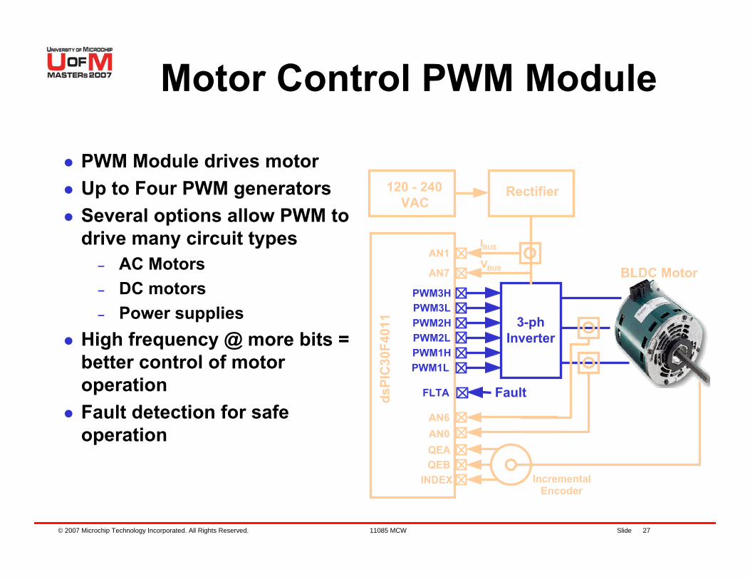
Motor Control PWM Module
PWM Module drives motorUp to Four PWM generatorsSeveral options allow PWM to drive many circuit types
– AC Motors– DC motors– Power supplies
High frequency @ more bits = better control of motor operationFault detection for safe operation
3-phInverter
VBUS
AN6AN0QEAQEB
INDEX
AN7
PWM3HPWM3LPWM2HPWM2LPWM1HPWM1L
FLTA Fault
IBUSAN1
BLDC Motor
IncrementalEncoder
dsPI
C30
F401
1
120 - 240VAC
Rectifier
© 2007 Microchip Technology Incorporated. All Rights Reserved. 11085 MCW Slide 28
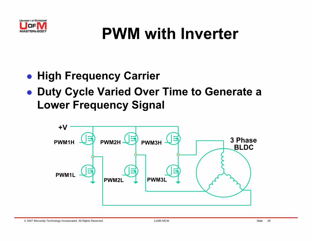
High Frequency CarrierDuty Cycle Varied Over Time to Generate a Lower Frequency Signal
+V
PWM1H
PWM1L
3 PhaseBLDC
PWM2H
PWM2L
PWM3H
PWM3L
PWM with Inverter
© 2007 Microchip Technology Incorporated. All Rights Reserved. 11085 MCW Slide 29
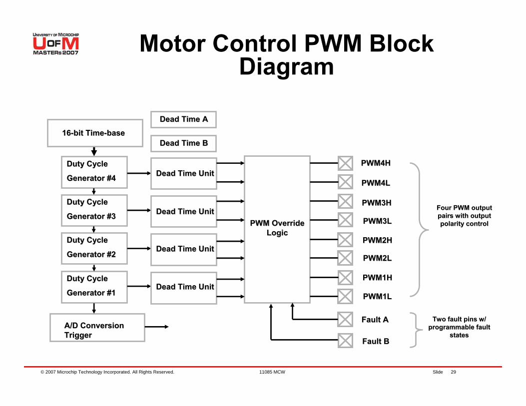
Motor Control PWM Block Diagram
Four PWM output Four PWM output pairs with output pairs with output polarity controlpolarity control
Duty CycleDuty Cycle
Generator #3Generator #3
Duty CycleDuty Cycle
Generator #2Generator #2
Duty CycleDuty Cycle
Generator #1Generator #1
Duty CycleDuty Cycle
Generator #4Generator #4
PWM Override PWM Override LogicLogic
Dead Time UnitDead Time Unit
Dead Time UnitDead Time Unit
Dead Time UnitDead Time Unit
Dead Time UnitDead Time Unit
Fault AFault A
Fault BFault B
PWM4HPWM4H
PWM1LPWM1L
PWM1HPWM1H
PWM2LPWM2L
PWM2HPWM2H
PWM3LPWM3L
PWM3HPWM3H
PWM4LPWM4L
Two fault pins w/ Two fault pins w/ programmable fault programmable fault
statesstates
1616--bit Timebit Time--basebase
A/D Conversion A/D Conversion TriggerTrigger
Dead Time ADead Time A
Dead Time BDead Time B
© 2007 Microchip Technology Incorporated. All Rights Reserved. 11085 MCW Slide 30
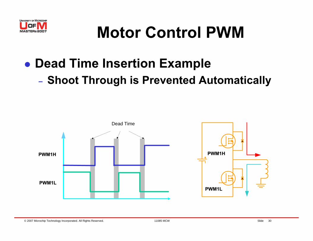
Motor Control PWM
Dead Time Insertion Example– Shoot Through is Prevented Automatically
PWM1HPWM1H
PWM1LPWM1L
Dead Time
PWM1HPWM1H
PWM1LPWM1L
© 2007 Microchip Technology Incorporated. All Rights Reserved. 11085 MCW Slide 31
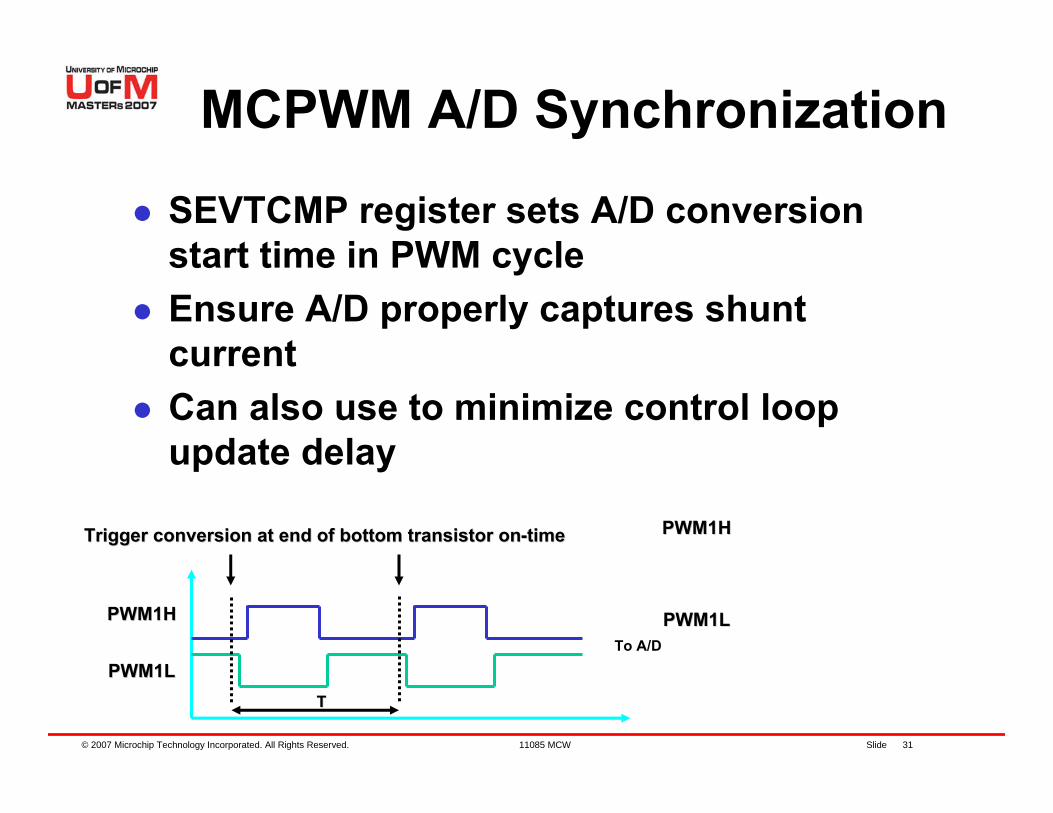
MCPWM A/D Synchronization
SEVTCMP register sets A/D conversion start time in PWM cycleEnsure A/D properly captures shunt currentCan also use to minimize control loop update delay
To A/DPWM1LPWM1L
PWM1HPWM1H
PWM1HPWM1H
PWM1LPWM1L
Trigger conversion at end of bottom transistor onTrigger conversion at end of bottom transistor on--timetime
TT
© 2007 Microchip Technology Incorporated. All Rights Reserved. 11085 MCW Slide 32
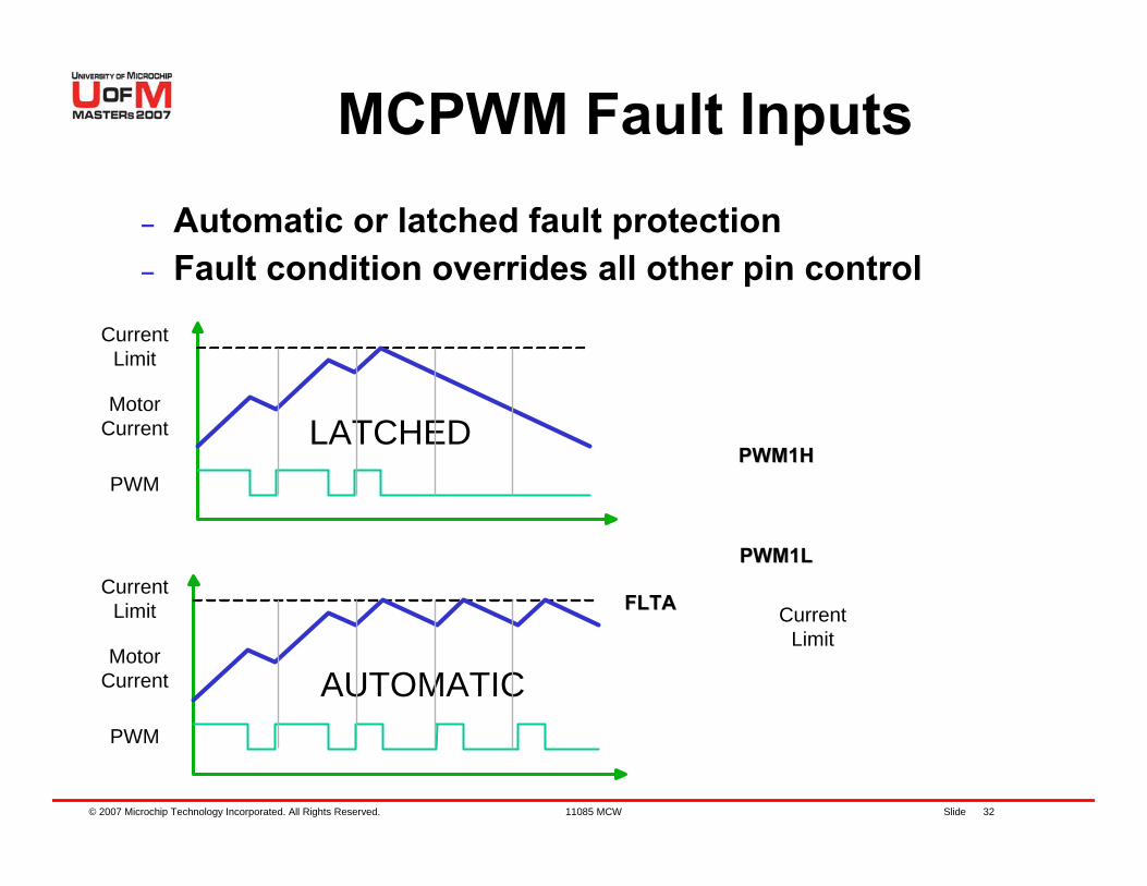
MCPWM Fault Inputs– Automatic or latched fault protection– Fault condition overrides all other pin control
CurrentLimit
PWM1LPWM1L
PWM1HPWM1H
FLTAFLTA
CurrentLimit
MotorCurrent
PWM
LATCHED
CurrentLimit
MotorCurrent
PWM
AUTOMATIC
© 2007 Microchip Technology Incorporated. All Rights Reserved. 11085 MCW Slide 33
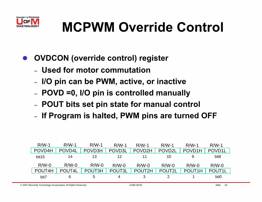
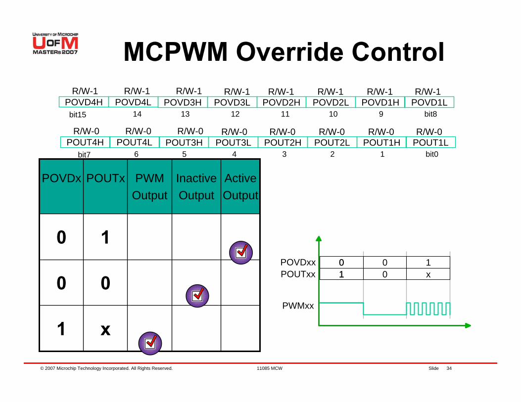
MCPWM Override Control
OVDCON (override control) register– Used for motor commutation– I/O pin can be PWM, active, or inactive– POVD =0, I/O pin is controlled manually– POUT bits set pin state for manual control– If Program is halted, PWM pins are turned OFF
POUT1LR/W-0 R/W-0 R/W-0 R/W-0 R/W-0 R/W-0 R/W-0 R/W-0
bit7 6 5 4 3 2 1 bit0POUT1HPOUT2LPOUT2HPOUT3LPOUT3HPOUT4LPOUT4H
POVD1LR/W-1 R/W-1 R/W-1 R/W-1 R/W-1 R/W-1 R/W-1 R/W-1
bit15 14 13 12 11 10 9 bit8POVD1HPOVD2LPOVD2HPOVD3LPOVD3HPOVD4LPOVD4H
© 2007 Microchip Technology Incorporated. All Rights Reserved. 11085 MCW Slide 34
MCPWM Override Control
POUT1LR/W-0 R/W-0 R/W-0 R/W-0 R/W-0 R/W-0 R/W-0 R/W-0
bit7 6 5 4 3 2 1 bit0POUT1HPOUT2LPOUT2HPOUT3LPOUT3HPOUT4LPOUT4H
POVD1LR/W-1 R/W-1 R/W-1 R/W-1 R/W-1 R/W-1 R/W-1 R/W-1
bit15 14 13 12 11 10 9 bit8POVD1HPOVD2LPOVD2HPOVD3LPOVD3HPOVD4LPOVD4H
x1
00
10
Active Output
Inactive Output
PWM Output
POUTxPOVDx
PWMxx
01
00
1x
POVDxxPOUTxx
01
© 2007 Microchip Technology Incorporated. All Rights Reserved. 11085 MCW Slide 35
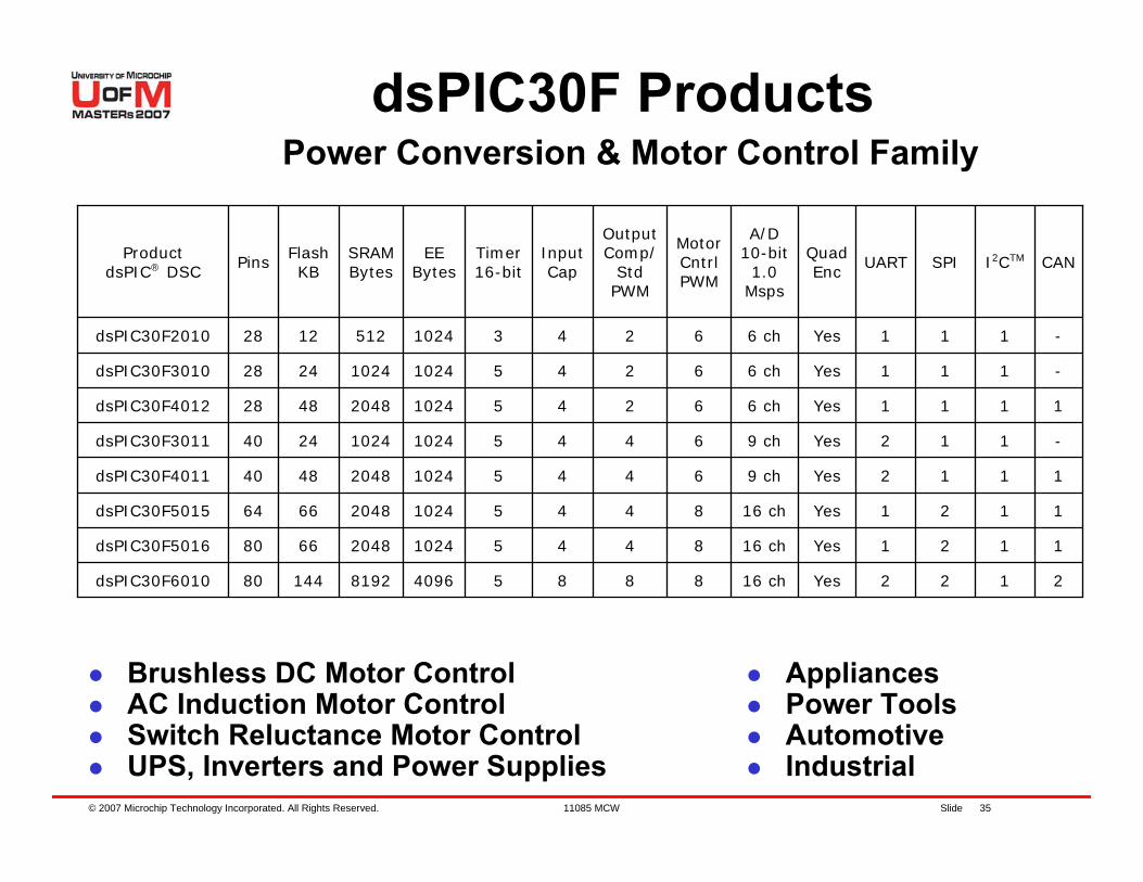
Brushless DC Motor ControlAC Induction Motor ControlSwitch Reluctance Motor ControlUPS, Inverters and Power Supplies
AppliancesPower ToolsAutomotiveIndustrial
2122Yes16 ch88854096819214480dsPIC30F6010
1121Yes16 ch8445102420486680dsPIC30F5016
1121Yes16 ch8445102420486664dsPIC30F5015
1112Yes9 ch6445102420484840dsPIC30F4011
-112Yes9 ch6445102410242440dsPIC30F3011
1111Yes6 ch6245102420484828dsPIC30F4012
-111Yes6 ch6245102410242428dsPIC30F3010
-111Yes6 ch624310245121228dsPIC30F2010
CANI2CTMSPIUARTQuad Enc
A/D 10-bit1.0
Msps
Motor CntrlPWM
OutputComp/
StdPWM
InputCap
Timer16-bit
EEBytes
SRAMBytes
FlashKB
PinsProductdsPIC® DSC
dsPIC30F ProductsPower Conversion & Motor Control Family
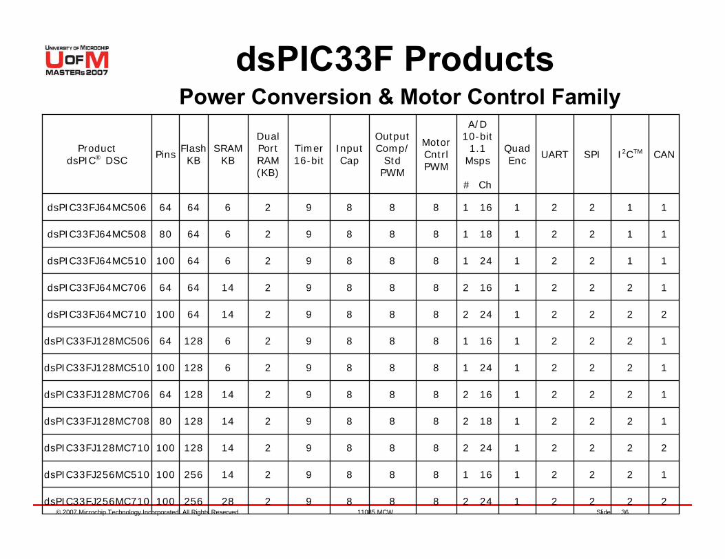
© 2007 Microchip Technology Incorporated. All Rights Reserved. 11085 MCW Slide 36
dsPIC33F ProductsPower Conversion & Motor Control Family
222212 248889214128100dsPIC33FJ128MC710
122211 168889214256100dsPIC33FJ256MC510
122212 16888921412864dsPIC33FJ128MC706
122212 18888921412880dsPIC33FJ128MC708
222212 248889228256100dsPIC33FJ256MC710
122211 24888926128100dsPIC33FJ128MC510
122211 1688892612864dsPIC33FJ128MC506
222212 24888921464100dsPIC33FJ64MC710
122212 1688892146464dsPIC33FJ64MC706
112211 2488892664100dsPIC33FJ64MC510
112211 188889266480dsPIC33FJ64MC508
112211 168889266464dsPIC33FJ64MC506
CANI2CTMSPIUARTQuad Enc
A/D 10-bit1.1
Msps
# Ch
Motor CntrlPWM
OutputComp/
StdPWM
InputCap
Timer16-bit
Dual Port RAM (KB)
SRAMKB
FlashKBPins
ProductdsPIC® DSC
© 2007 Microchip Technology Incorporated. All Rights Reserved. 11085 MCW Slide 37
Lab 1 – Programming a dsPIC® DSC Using the
PICDEM™ MCLV Board
© 2007 Microchip Technology Incorporated. All Rights Reserved. 11085 MCW Slide 38
Objectives of Lab 1
Getting to know the hardware in front of youVerify your set-upWhere are the Labs located?– C:\RTC\301MCW\Lab1\Lab1.mcw
How to load the lab projectsProgramming the dsPIC® DSC devicesRunning the program on dsPIC® DSC
© 2007 Microchip Technology Incorporated. All Rights Reserved. 11085 MCW Slide 39
You should have….1) MPLAB® IDE V7.20 or higher installed2) Complete MPLAB® ICD 2 setup R20 or Latest Rev. 3) PICDEM™ MCLV board4) 24V power supply for the board5) Hurst (NTDynamo®) BLDC motor with
– Power cable (4 wires with white square connector) and– Hall sensor cable (5 wires with 8-pin inline black connector)
© 2007 Microchip Technology Incorporated. All Rights Reserved. 11085 MCW Slide 40
Lab 1
What we will do:– Configure board hardware connections– Open a workspace in MPLAB® IDE– Compile or build a simple first project in
MPLAB® IDE– Follow a procedure to program the dsPIC®
DSC using MPLAB® ICD 2– Follow a procedure to run the program using
MPLAB® ICD 2
© 2007 Microchip Technology Incorporated. All Rights Reserved. 11085 MCW Slide 41
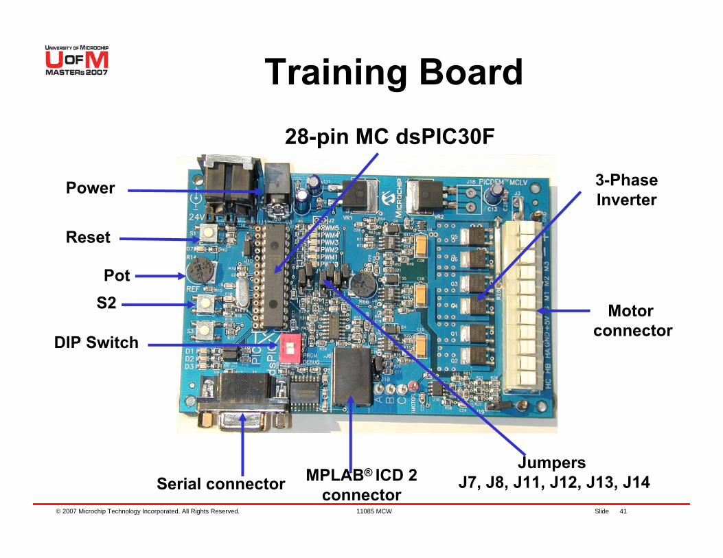
Training Board
Power
Reset
PotS2
DIP Switch
Serial connector MPLAB® ICD 2connector
Motor connector
28-pin MC dsPIC30F
JumpersJ7, J8, J11, J12, J13, J14
3-PhaseInverter
© 2007 Microchip Technology Incorporated. All Rights Reserved. 11085 MCW Slide 42
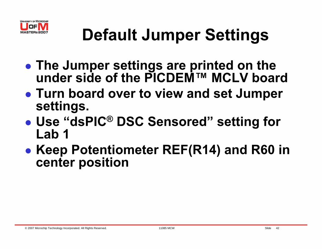
Default Jumper Settings
The Jumper settings are printed on the under side of the PICDEM™ MCLV boardTurn board over to view and set Jumper settings.Use “dsPIC® DSC Sensored” setting for Lab 1 Keep Potentiometer REF(R14) and R60 in center position
© 2007 Microchip Technology Incorporated. All Rights Reserved. 11085 MCW Slide 43
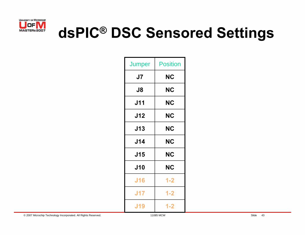
dsPIC® DSC Sensored Settings
1-2J19
1-2J17
1-2J16
NCJ10
NCJ15
NCJ14
NCJ13
NCJ12
NCJ11
NCJ8
NCJ7
PositionJumper
© 2007 Microchip Technology Incorporated. All Rights Reserved. 11085 MCW Slide 44
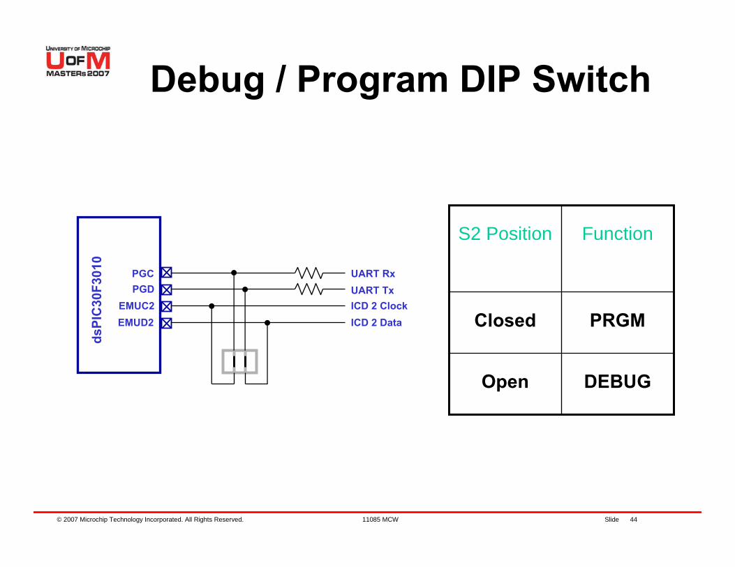
Debug / Program DIP Switch
PGCPGD
EMUC2EMUD2
dsPI
C30
F301
0
DEBUGOpen
PRGMClosed
FunctionS2 Position
UART RxUART TxICD 2 ClockICD 2 Data
© 2007 Microchip Technology Incorporated. All Rights Reserved. 11085 MCW Slide 45
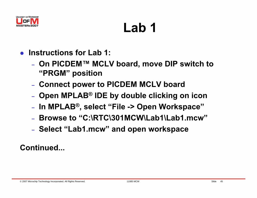
Lab 1
Instructions for Lab 1:– On PICDEM™ MCLV board, move DIP switch to
“PRGM” position – Connect power to PICDEM MCLV board– Open MPLAB® IDE by double clicking on icon– In MPLAB®, select “File -> Open Workspace”– Browse to “C:\RTC\301MCW\Lab1\Lab1.mcw”– Select “Lab1.mcw” and open workspace
Continued...
© 2007 Microchip Technology Incorporated. All Rights Reserved. 11085 MCW Slide 46
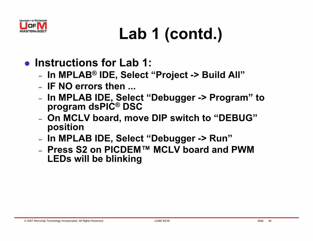
Lab 1 (contd.)
Instructions for Lab 1:– In MPLAB® IDE, Select “Project -> Build All”– IF NO errors then ...– In MPLAB IDE, Select “Debugger -> Program” to
program dsPIC® DSC– On MCLV board, move DIP switch to “DEBUG”
position– In MPLAB IDE, Select “Debugger -> Run”– Press S2 on PICDEM™ MCLV board and PWM
LEDs will be blinking
© 2007 Microchip Technology Incorporated. All Rights Reserved. 11085 MCW Slide 47
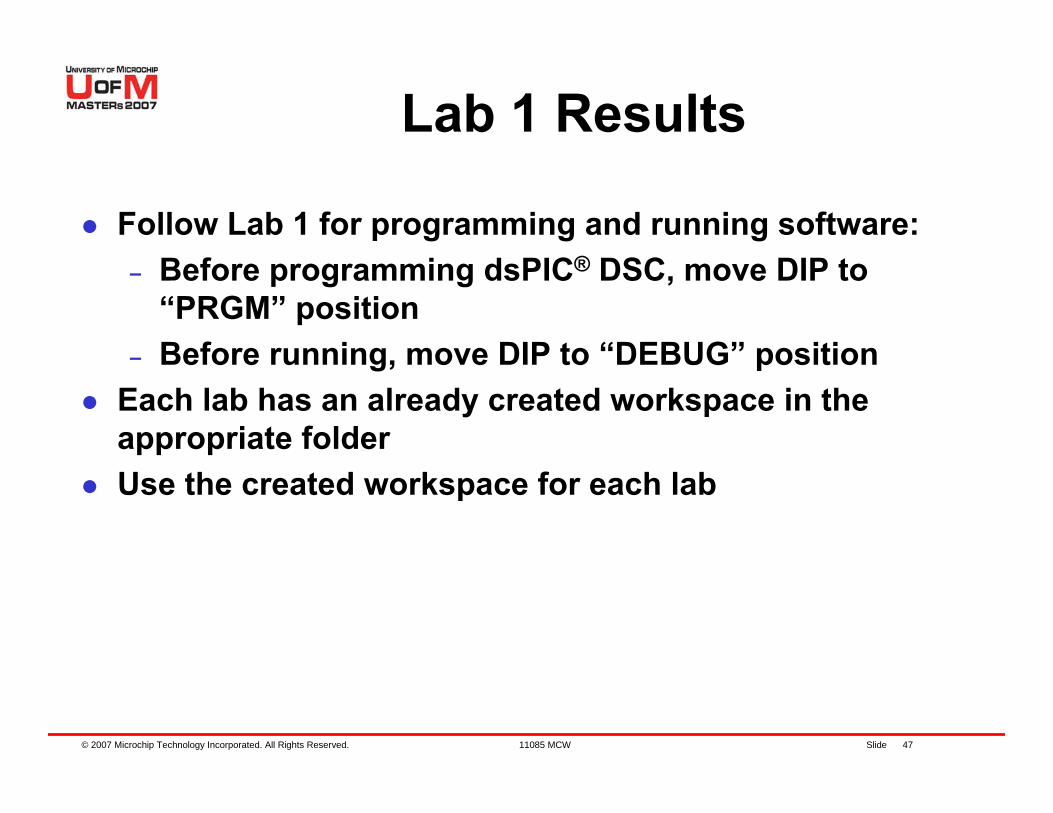
Lab 1 Results
Follow Lab 1 for programming and running software:– Before programming dsPIC® DSC, move DIP to
“PRGM” position – Before running, move DIP to “DEBUG” position
Each lab has an already created workspace in the appropriate folderUse the created workspace for each lab
© 2007 Microchip Technology Incorporated. All Rights Reserved. 11085 MCW Slide 48
BLDC Motor Introduction
© 2007 Microchip Technology Incorporated. All Rights Reserved. 11085 MCW Slide 49
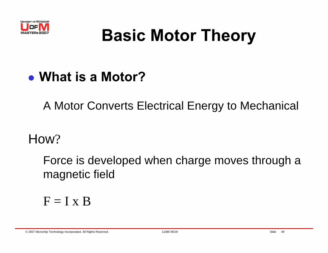
Basic Motor Theory
What is a Motor?
How?
A Motor Converts Electrical Energy to Mechanical
Force is developed when charge moves through a magnetic field
F = I x B
© 2007 Microchip Technology Incorporated. All Rights Reserved. 11085 MCW Slide 50
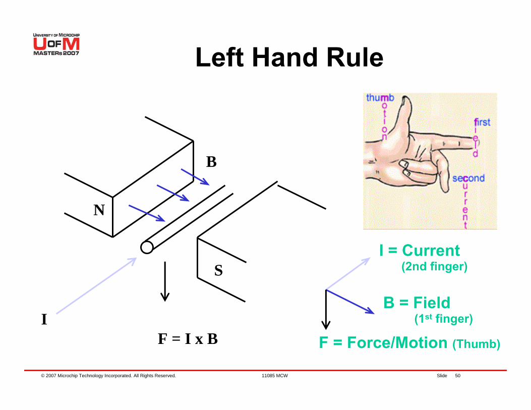
Left Hand Rule
I
B
F = I x B
N
S
F = Force/Motion (Thumb)
I = Current(2nd finger)
B = Field(1st finger)
© 2007 Microchip Technology Incorporated. All Rights Reserved. 11085 MCW Slide 51
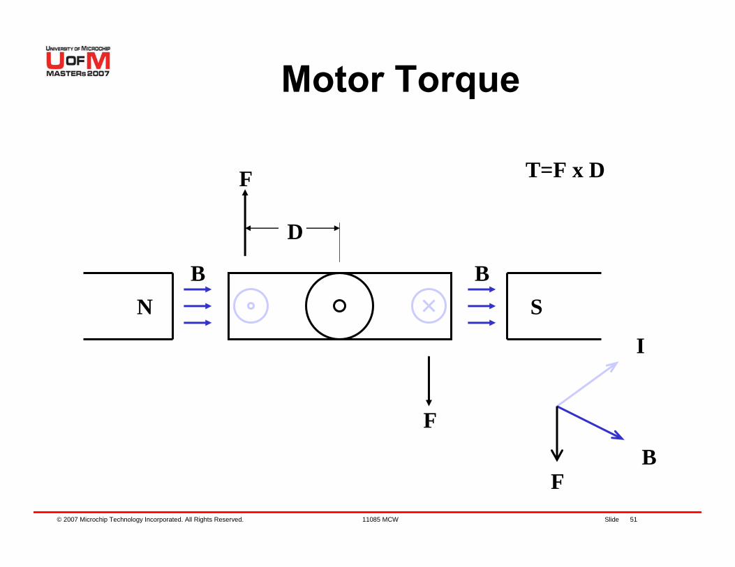
Motor Torque
B BSN
I
BF
T=F x D
D
F
F
© 2007 Microchip Technology Incorporated. All Rights Reserved. 11085 MCW Slide 52
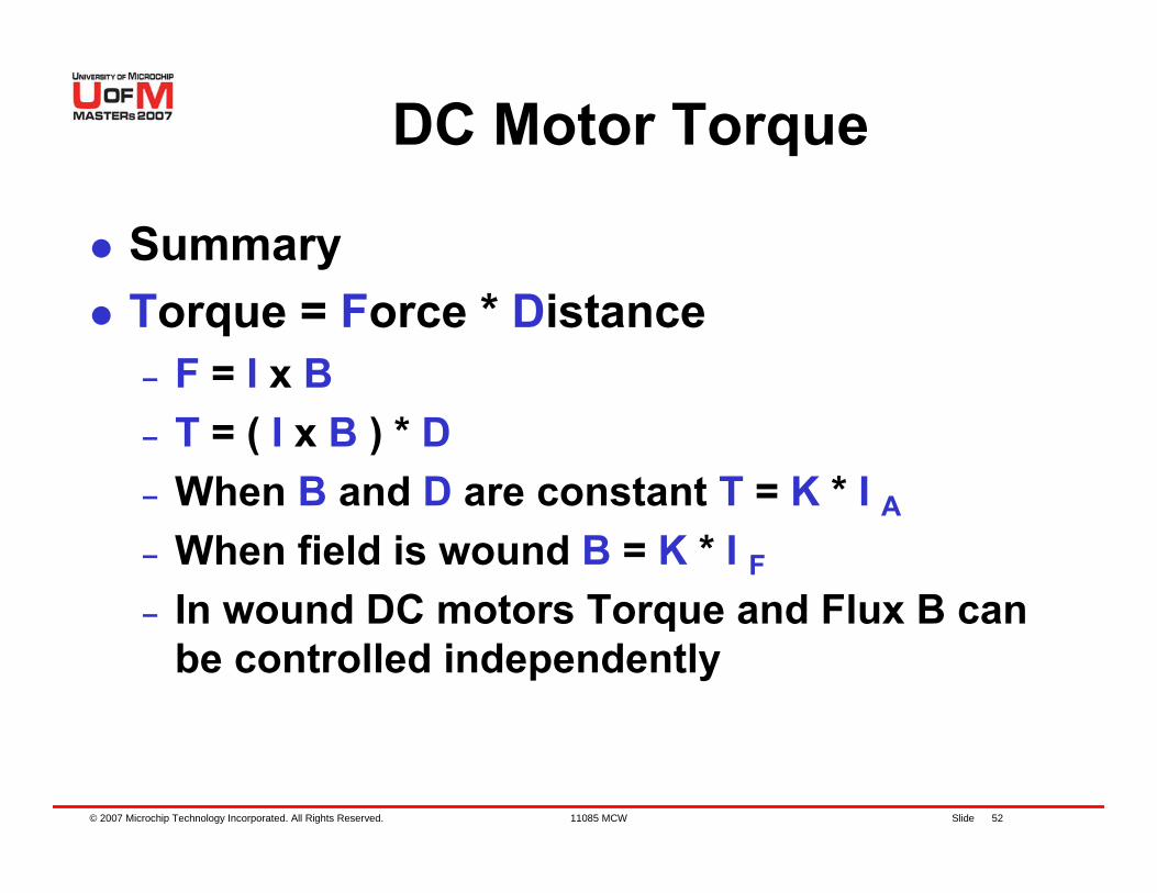
DC Motor Torque
SummaryTorque = Force * Distance– F = I x B– T = ( I x B ) * D– When B and D are constant T = K * I A– When field is wound B = K * I F– In wound DC motors Torque and Flux B can
be controlled independently
© 2007 Microchip Technology Incorporated. All Rights Reserved. 11085 MCW Slide 53
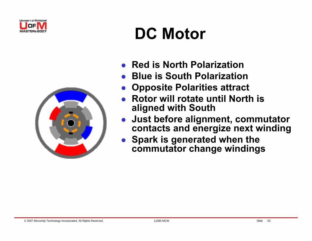
DC Motor
Red is North PolarizationBlue is South PolarizationOpposite Polarities attractRotor will rotate until North is aligned with SouthJust before alignment, commutator contacts and energize next windingSpark is generated when the commutator change windings
© 2007 Microchip Technology Incorporated. All Rights Reserved. 11085 MCW Slide 54
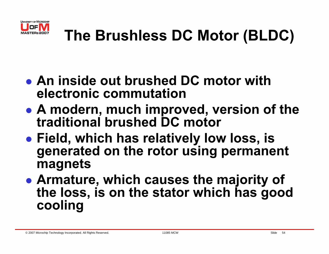
The Brushless DC Motor (BLDC)
An inside out brushed DC motor with electronic commutationA modern, much improved, version of the traditional brushed DC motorField, which has relatively low loss, is generated on the rotor using permanent magnetsArmature, which causes the majority of the loss, is on the stator which has good cooling
© 2007 Microchip Technology Incorporated. All Rights Reserved. 11085 MCW Slide 55
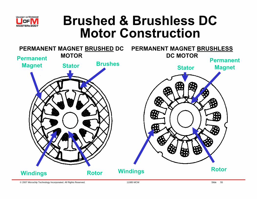
Brushed & Brushless DC Motor Construction
PERMANENT MAGNET BRUSHED DC MOTOR
PERMANENT MAGNET BRUSHLESSDC MOTORPermanent
MagnetPermanent
Magnet
Windings
Stator Brushes
Rotor RotorWindings
Stator
© 2007 Microchip Technology Incorporated. All Rights Reserved. 11085 MCW Slide 56
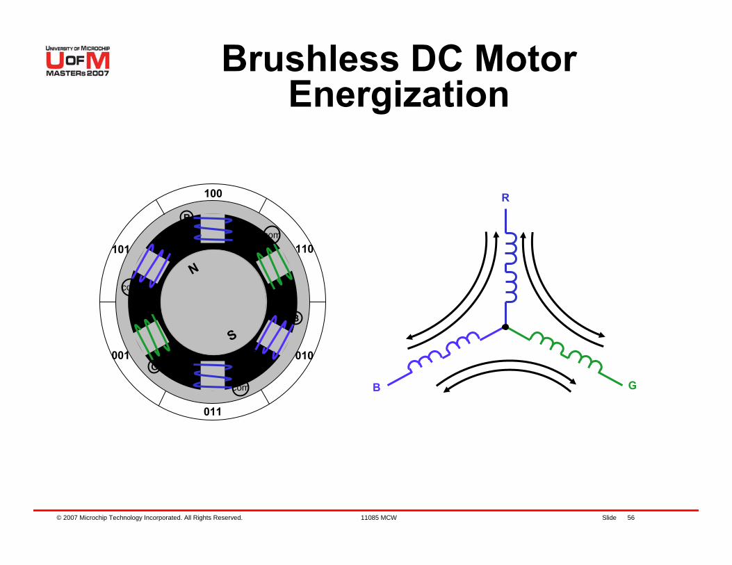
Brushless DC Motor Energization
100
N
S
R
B
r
r
gg
b
bG
com
com
com
110
010
011
101
001
R
GB
N
S
© 2007 Microchip Technology Incorporated. All Rights Reserved. 11085 MCW Slide 57
BLDC Advantages OverBrushed DC Motor
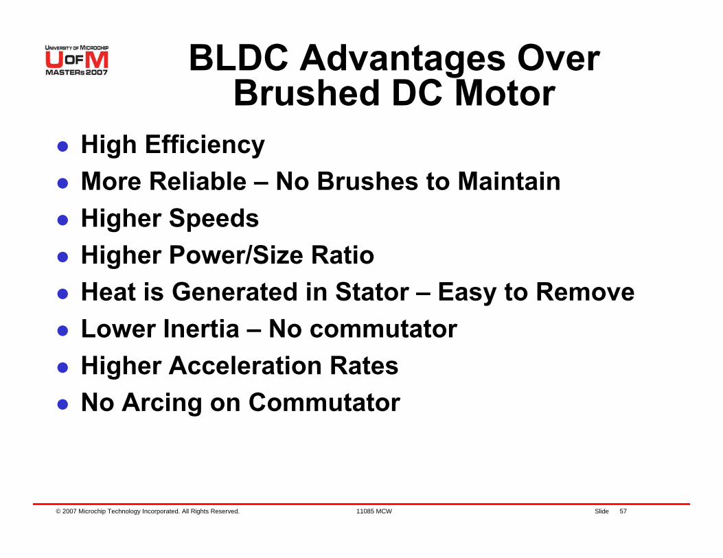
High EfficiencyMore Reliable – No Brushes to MaintainHigher SpeedsHigher Power/Size RatioHeat is Generated in Stator – Easy to RemoveLower Inertia – No commutator Higher Acceleration RatesNo Arcing on Commutator
© 2007 Microchip Technology Incorporated. All Rights Reserved. 11085 MCW Slide 58
BLDC Control
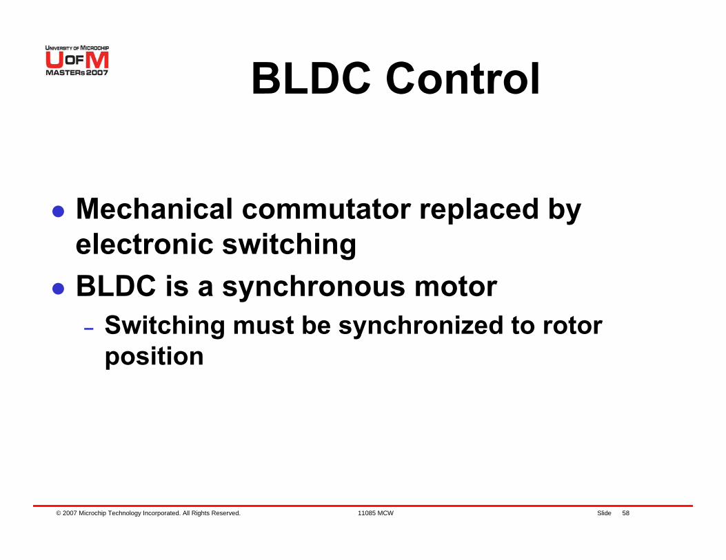
Mechanical commutator replaced by electronic switchingBLDC is a synchronous motor– Switching must be synchronized to rotor
position
© 2007 Microchip Technology Incorporated. All Rights Reserved. 11085 MCW Slide 59
Lab 2 – Running a BLDC Motor with
Forced Commutation
© 2007 Microchip Technology Incorporated. All Rights Reserved. 11085 MCW Slide 60
Running a BLDC Motor with Forced Commutation
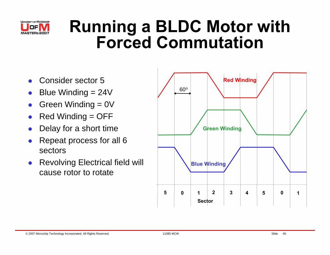
Consider sector 5Blue Winding = 24VGreen Winding = 0VRed Winding = OFFDelay for a short timeRepeat process for all 6 sectorsRevolving Electrical field will cause rotor to rotate
60o
Sector5 0 1 2 3 4 5 0 1
Blue Winding
Green Winding
Red Winding
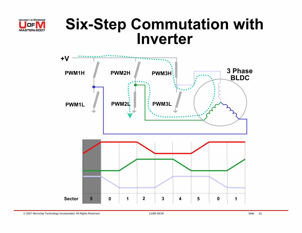
© 2007 Microchip Technology Incorporated. All Rights Reserved. 11085 MCW Slide 61
Six-Step Commutation with Inverter
+V
PWM1H
PWM1L
3 PhaseBLDC
PWM2H
PWM2L
PWM3H
PWM3L
Sector 5 0 1 2 3 4 5 0 1
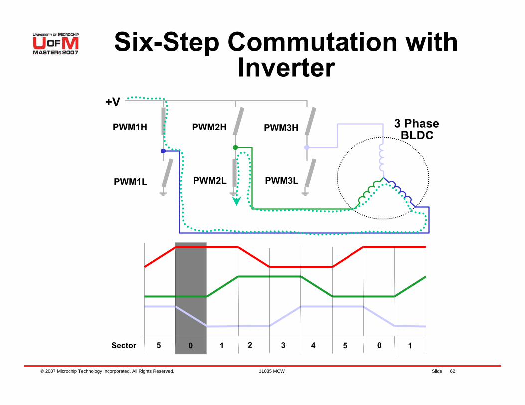
© 2007 Microchip Technology Incorporated. All Rights Reserved. 11085 MCW Slide 62
+V
PWM1H
PWM1L
3 PhaseBLDC
PWM2H
PWM2L
PWM3H
PWM3L
Sector 5 0 1 2 3 4 5 0 1
Six-Step Commutation with Inverter
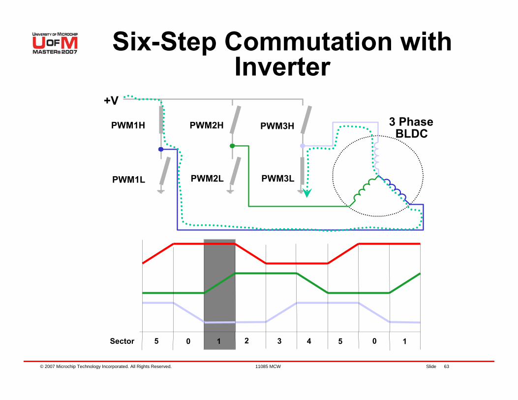
© 2007 Microchip Technology Incorporated. All Rights Reserved. 11085 MCW Slide 63
+V
PWM1H
PWM1L
3 PhaseBLDC
PWM2H
PWM2L
PWM3H
PWM3L
Sector 5 0 1 2 3 4 5 0 1
Six-Step Commutation with Inverter
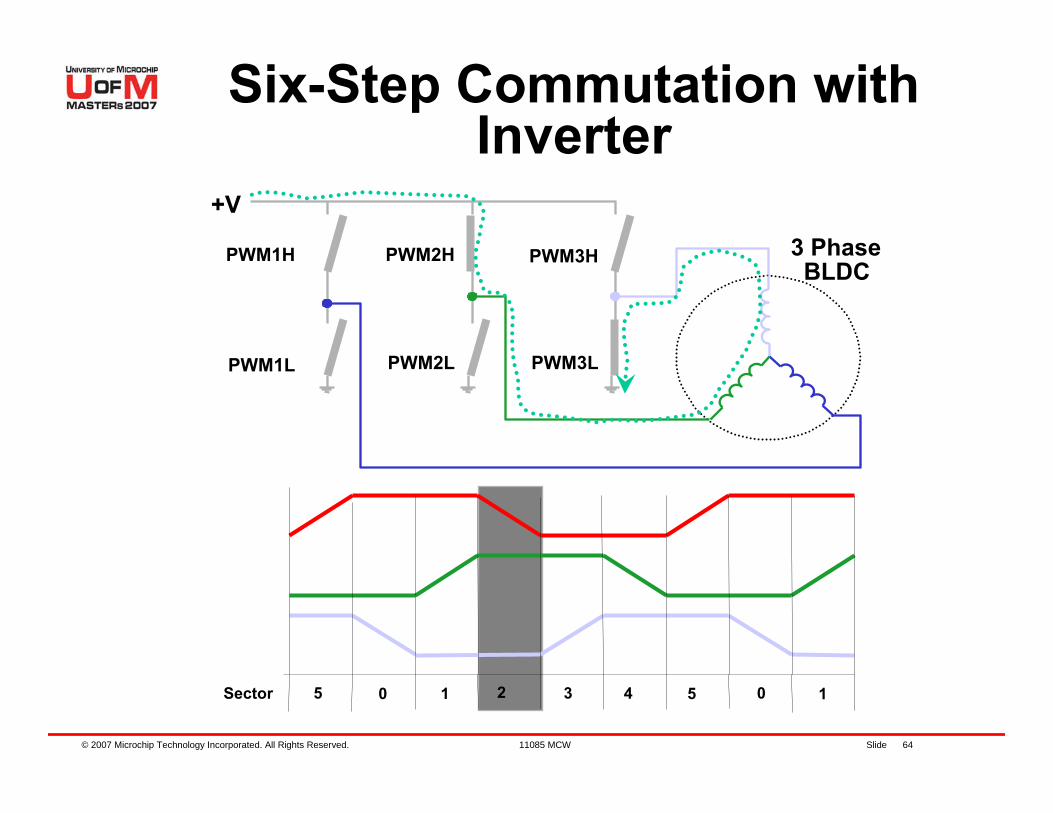
© 2007 Microchip Technology Incorporated. All Rights Reserved. 11085 MCW Slide 64
+V
PWM1H
PWM1L
3 PhaseBLDC
PWM2H
PWM2L
PWM3H
PWM3L
Sector 5 0 1 2 3 4 5 0 1
Six-Step Commutation with Inverter
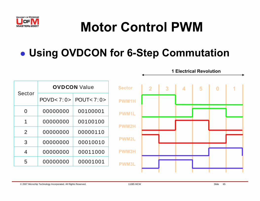
© 2007 Microchip Technology Incorporated. All Rights Reserved. 11085 MCW Slide 65
1 Electrical Revolution
Motor Control PWM
Using OVDCON for 6-Step Commutation
POVD<7:0> POUT<7:0>
0 00000000 00100001
1 00000000 00100100
2 00000000 00000110
3 00000000 00010010
4 00000000 00011000
5 00000000 00001001
OVDCON ValueSector
3 4 5 0 12
PWM1H
PWM1L
PWM2H
PWM2L
PWM3H
PWM3L
Sector

© 2007 Microchip Technology Incorporated. All Rights Reserved. 11085 MCW Slide 66
3-PhaseInverter BLDCMain State
Machine
Start /Stop
3-Phase Voltages
PeriodicISR
6-Step Generation
dsPIC30F
GPI
O
GPI
O
Peripheral Block
Software Block
Running a BLDC Motor with Forced Commutation
© 2007 Microchip Technology Incorporated. All Rights Reserved. 11085 MCW Slide 67
Instructions for Lab 2:– Use workspace
“C:\RTC\301MCW\Lab2\Lab2.mcw”– Follow Lab 1 instructions to:
Compile codeProgram dsPIC® DSC Run code
Continued...
Lab 2 – Running a BLDC Motor with Forced Commutation
© 2007 Microchip Technology Incorporated. All Rights Reserved. 11085 MCW Slide 68
Press S2 to start motorNotice that the motor is running rough and loud (almost screeching)Notice that the motor is getting warm.WHY?Press S2 to Stop the motor
Lab 2 – Running a BLDC Motor with Forced Commutation
© 2007 Microchip Technology Incorporated. All Rights Reserved. 11085 MCW Slide 69
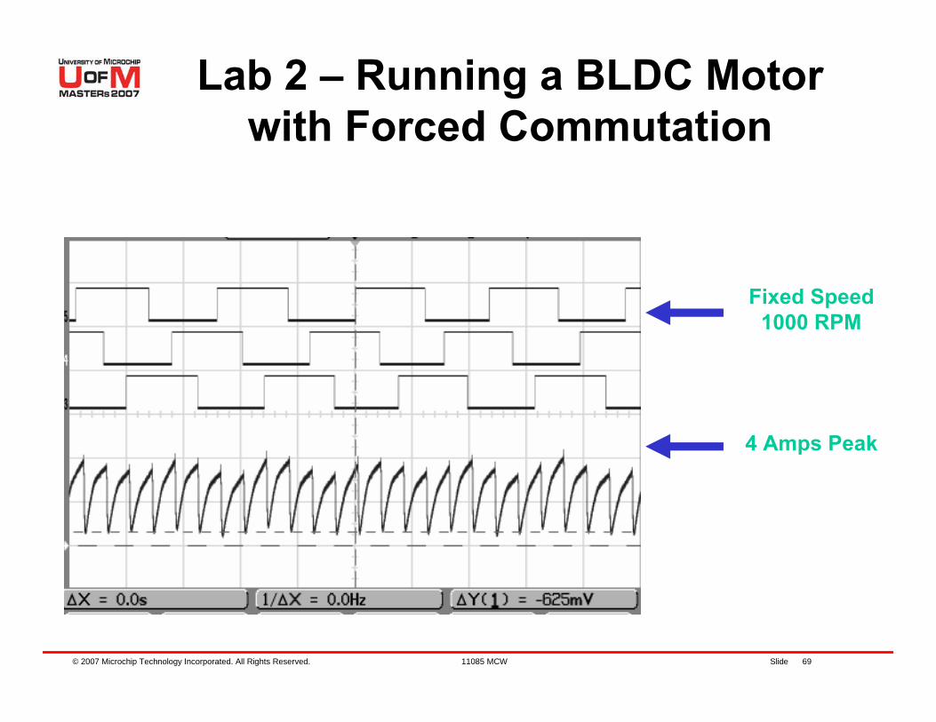
4 Amps Peak
Fixed Speed1000 RPM
Lab 2 – Running a BLDC Motor with Forced Commutation
© 2007 Microchip Technology Incorporated. All Rights Reserved. 11085 MCW Slide 70
Details of Program
Use MPLAB® IDE to go thru sections of the code
© 2007 Microchip Technology Incorporated. All Rights Reserved. 11085 MCW Slide 71
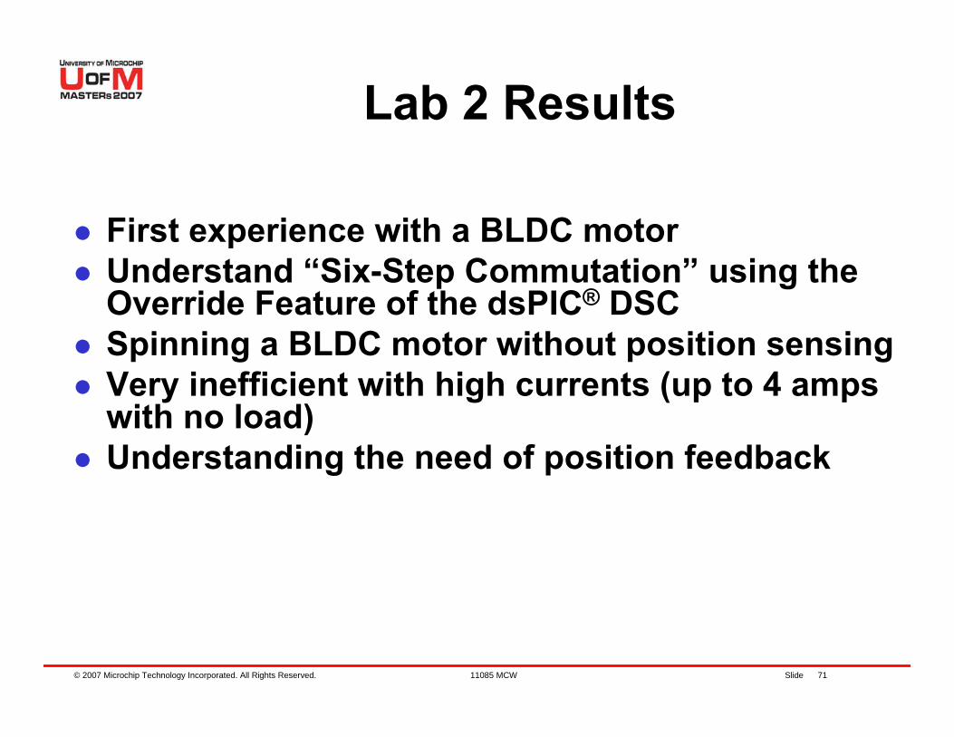
Lab 2 Results
First experience with a BLDC motorUnderstand “Six-Step Commutation” using the Override Feature of the dsPIC® DSCSpinning a BLDC motor without position sensingVery inefficient with high currents (up to 4 amps with no load)Understanding the need of position feedback
© 2007 Microchip Technology Incorporated. All Rights Reserved. 11085 MCW Slide 72
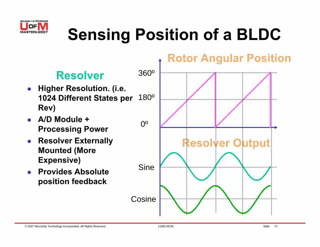
ResolverHigher Resolution. (i.e. 1024 Different States per Rev)A/D Module + Processing PowerResolver Externally Mounted (More Expensive)Provides Absolute position feedback
Cosine
Sine
Resolver Output
Rotor Angular Position
0º
180º
360º
Sensing Position of a BLDC
© 2007 Microchip Technology Incorporated. All Rights Reserved. 11085 MCW Slide 73
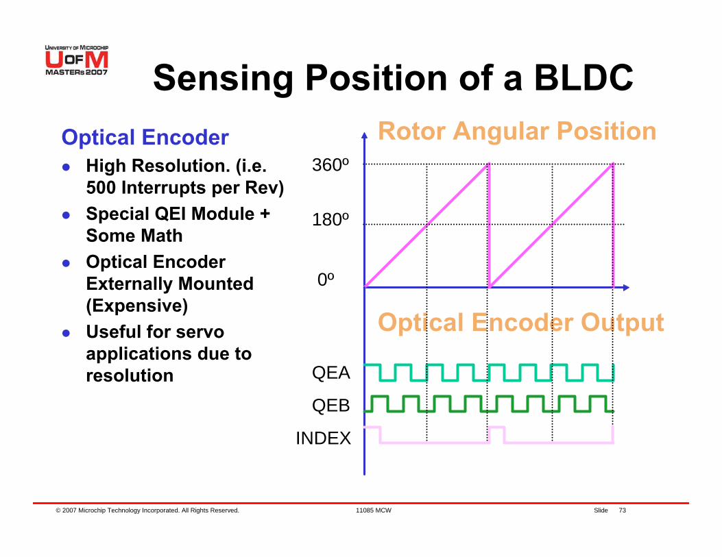
Optical EncoderHigh Resolution. (i.e. 500 Interrupts per Rev)Special QEI Module + Some MathOptical Encoder Externally Mounted (Expensive)Useful for servo applications due to resolution
INDEX
QEB
QEA
0º
180º
360º
Optical Encoder Output
Rotor Angular Position
Sensing Position of a BLDC
© 2007 Microchip Technology Incorporated. All Rights Reserved. 11085 MCW Slide 74
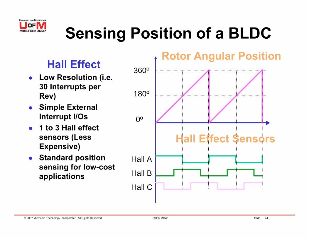
Hall EffectLow Resolution (i.e. 30 Interrupts per Rev)Simple External Interrupt I/Os1 to 3 Hall effect sensors (Less Expensive)Standard position sensing for low-cost applications
Hall A
0º
180º
360º
Hall B
Hall C
Hall Effect Sensors
Rotor Angular Position
Sensing Position of a BLDC
© 2007 Microchip Technology Incorporated. All Rights Reserved. 11085 MCW Slide 75
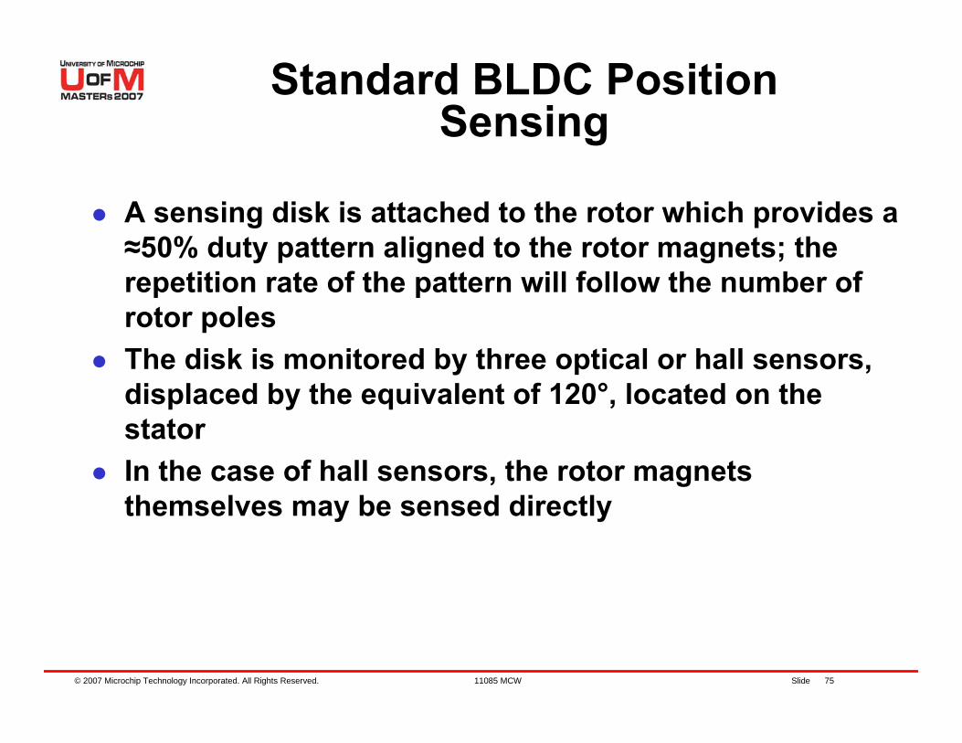
A sensing disk is attached to the rotor which provides a ≈50% duty pattern aligned to the rotor magnets; the repetition rate of the pattern will follow the number of rotor polesThe disk is monitored by three optical or hall sensors, displaced by the equivalent of 120°, located on the statorIn the case of hall sensors, the rotor magnets themselves may be sensed directly
Standard BLDC Position Sensing
© 2007 Microchip Technology Incorporated. All Rights Reserved. 11085 MCW Slide 76
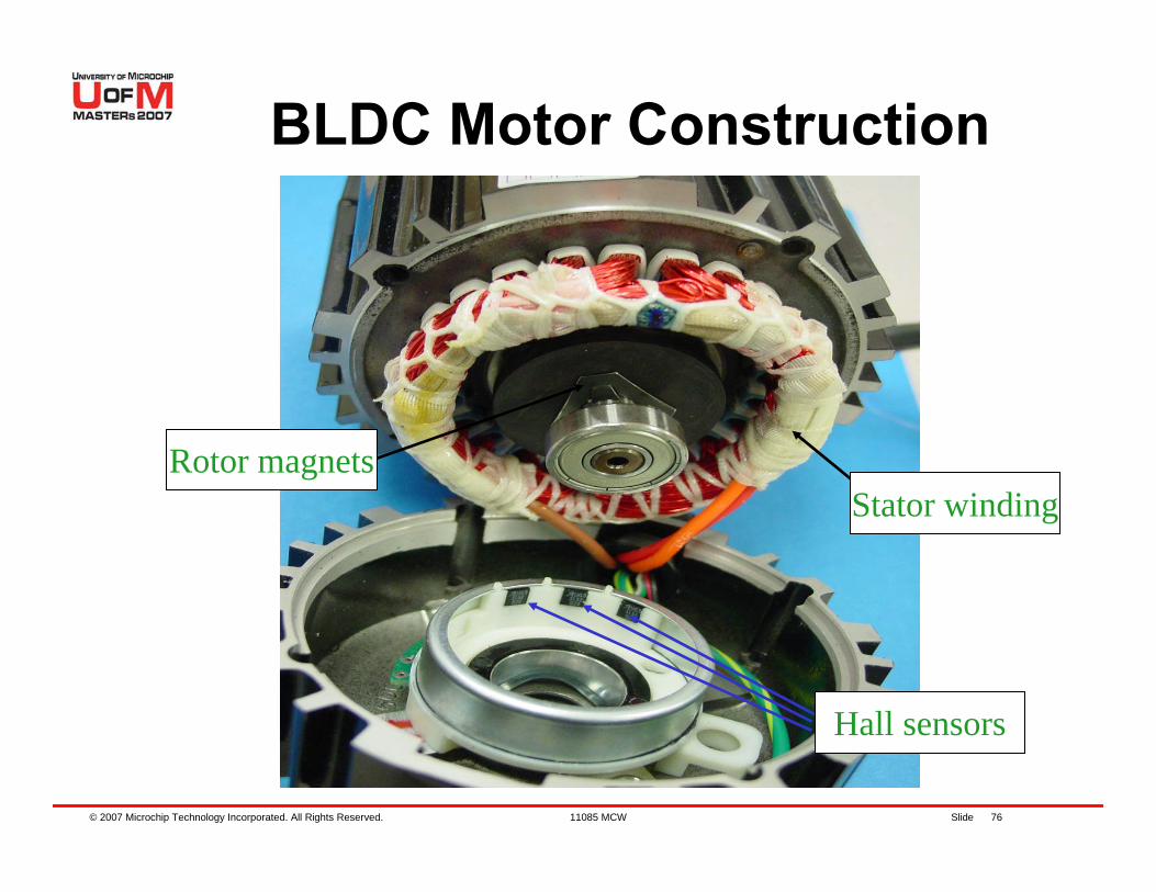
BLDC Motor Construction
Hall sensors
Stator windingRotor magnets
© 2007 Microchip Technology Incorporated. All Rights Reserved. 11085 MCW Slide 77
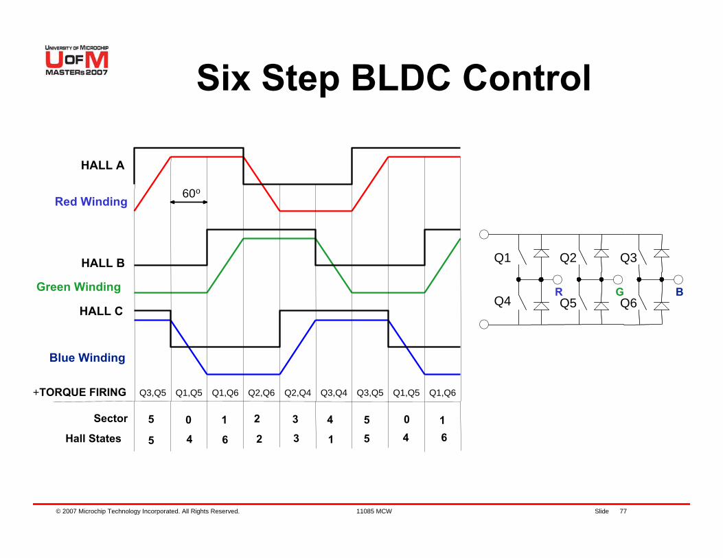
Six Step BLDC Control
+TORQUE FIRING
BR G
Q1 Q3Q2
Q4 Q6Q5Green Winding
Q1,Q5 Q1,Q6 Q2,Q6 Q2,Q4 Q3,Q4 Q3,Q5
60o
HALL A
HALL B
HALL C
Q1,Q5 Q1,Q6Q3,Q5
Sector 5
Hall States0 1 2
5 4 6 2
3
34
1
55
04
16
Blue Winding
Red Winding
© 2007 Microchip Technology Incorporated. All Rights Reserved. 11085 MCW Slide 78
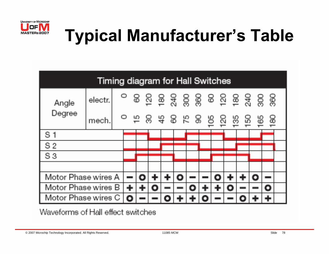
Typical Manufacturer’s Table
© 2007 Microchip Technology Incorporated. All Rights Reserved. 11085 MCW Slide 79
Lab 3 – Running Sensored BLDC Motor
with OVDCON
© 2007 Microchip Technology Incorporated. All Rights Reserved. 11085 MCW Slide 80
The 3 logic signals are decoded to determine which windings should be energizedThere are 6 valid states and 2 states that should never be seen (000, 111)Use Lookup table to drive the 3 windings, high or low or no-driveThe 6 different valid states directly translate to the 6 different 60° electrical cycle sectorsThe states should only transition by one at a time; missing transitions or invalid states should be detected for robust operation
Six Step Sensored BLDC Control
© 2007 Microchip Technology Incorporated. All Rights Reserved. 11085 MCW Slide 81
Lab 3 Jumper settings
Turn MCLV board over and refer to the jumper settings for “dsPIC® DSC Sensored”Keep Potentiometer REF(R14) and R60 in center positionConnect Hall Sensors to the Motor (Black Connector)Connect Motor Windings (White Connector) to Motor
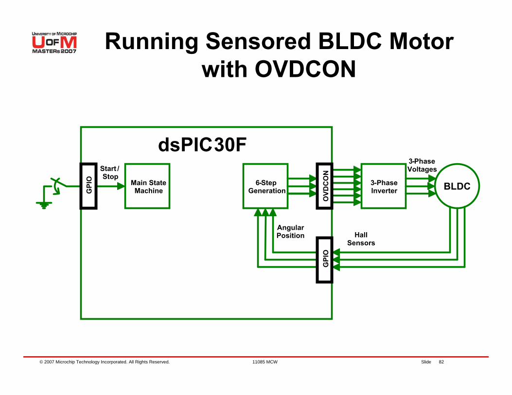
© 2007 Microchip Technology Incorporated. All Rights Reserved. 11085 MCW Slide 82
3-PhaseInverter BLDC6-Step
GenerationMain State Machine
Start /Stop
3-Phase Voltages
Hall Sensors
Angular Position
dsPIC30F
GPI
O
GPI
OO
VDC
ON
Running Sensored BLDC Motor with OVDCON
© 2007 Microchip Technology Incorporated. All Rights Reserved. 11085 MCW Slide 83
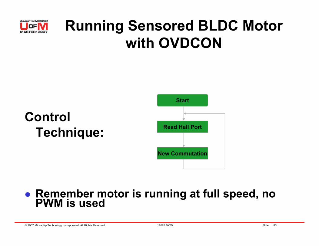
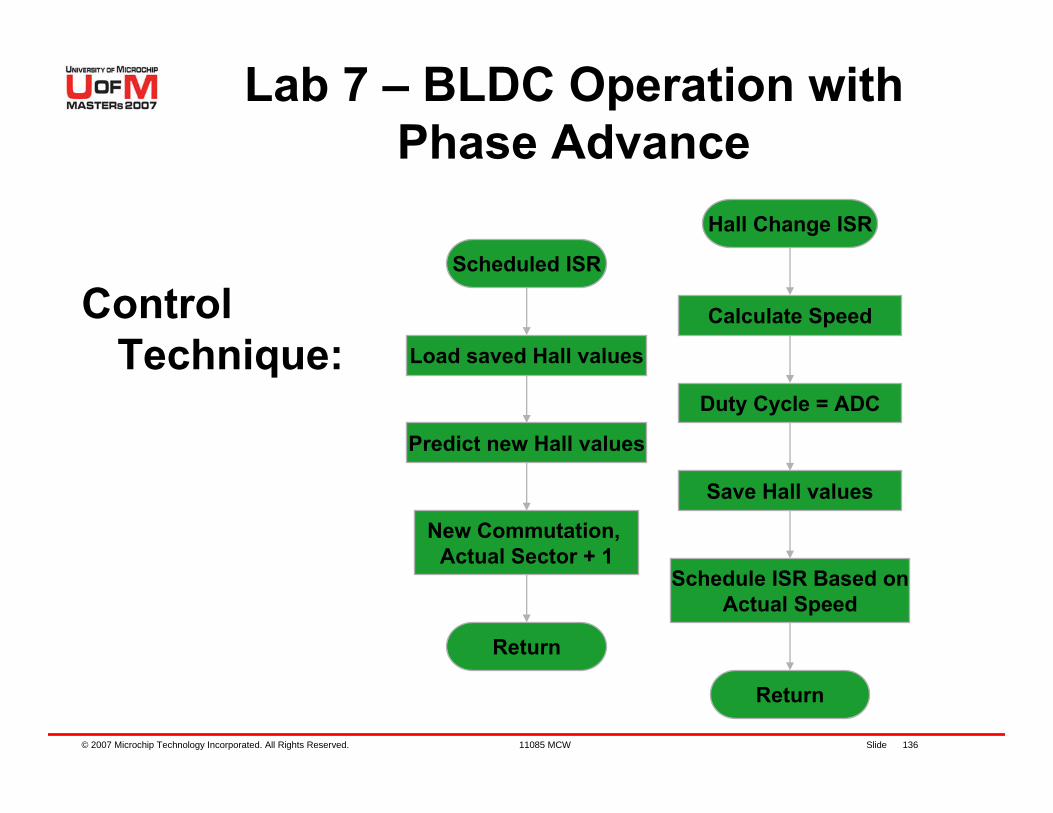
Control Technique:
Remember motor is running at full speed, no PWM is used
New Commutation
Read Hall Port
Start
Running Sensored BLDC Motor with OVDCON
© 2007 Microchip Technology Incorporated. All Rights Reserved. 11085 MCW Slide 84
Instructions for Lab 3:– Use workspace
“C:\RTC\\301MCW\Lab3\Lab3.mcw”– Follow Lab 1 instructions to:
Compile codeProgram the dsPIC® DSCRun code
Continued...
Lab 3 – Running Sensored BLDC Motor with OVDCON
© 2007 Microchip Technology Incorporated. All Rights Reserved. 11085 MCW Slide 85
Press S2 to start motorNotice that the motor is running very smoothlyNotice that the motor does not get warmWHY?Press S2 to stop the motor
Lab 3 – Running SensoredBLDC Motor with OVDCON
© 2007 Microchip Technology Incorporated. All Rights Reserved. 11085 MCW Slide 86
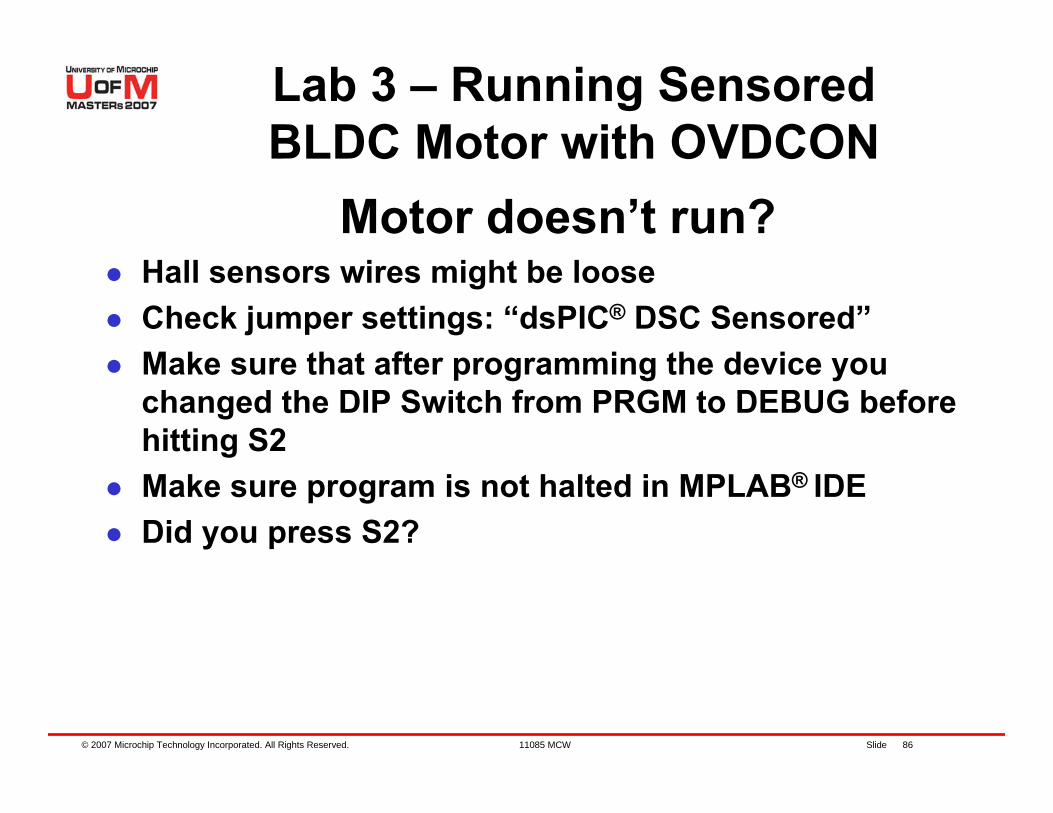
Motor doesn’t run?Hall sensors wires might be looseCheck jumper settings: “dsPIC® DSC Sensored”Make sure that after programming the device you changed the DIP Switch from PRGM to DEBUG before hitting S2Make sure program is not halted in MPLAB® IDEDid you press S2?
Lab 3 – Running SensoredBLDC Motor with OVDCON
© 2007 Microchip Technology Incorporated. All Rights Reserved. 11085 MCW Slide 87
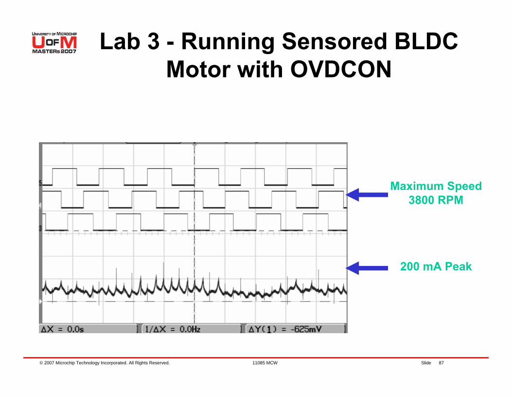
Lab 3 - Running Sensored BLDC Motor with OVDCON
200 mA Peak
Maximum Speed3800 RPM

© 2007 Microchip Technology Incorporated. All Rights Reserved. 11085 MCW Slide 88
Details of Program
Use MPLAB® IDE to go thru sections of the code
© 2007 Microchip Technology Incorporated. All Rights Reserved. 11085 MCW Slide 89
Lab 3 Results
Spinning a Sensored BLDC motor at full speedUnderstanding how sensors position and BLDC motor efficiency are relatedOVDCON will shut off the outputs if program execution is Halted, protecting the system HWWith no PWM we have fixed motor speed
© 2007 Microchip Technology Incorporated. All Rights Reserved. 11085 MCW Slide 90
Lab 4 – Running Sensored BLDC Motor
with MCPWM
© 2007 Microchip Technology Incorporated. All Rights Reserved. 11085 MCW Slide 91
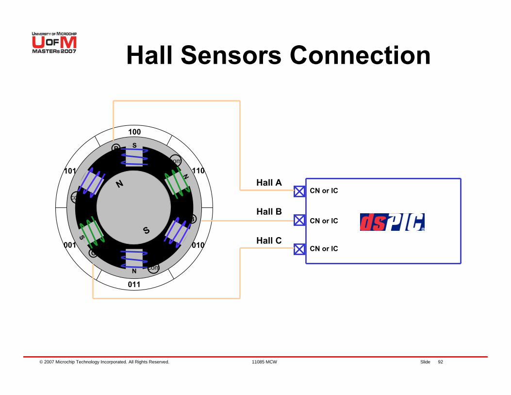
Change Notification (CN)
dsPIC® DSC has Change Notification inputs:– Detect digital changes on a specific input pin
and generates an interrupt– Hall sensors A, B and C are connected to RB3,
4 and 5 or CN4, 5 and 6 respectively– When CNxInterrupt occurs, all 3 Hall inputs
are read and a lookup table is used to control the BLDC motor
© 2007 Microchip Technology Incorporated. All Rights Reserved. 11085 MCW Slide 92
100
R
B
r
r
gg
b
bG
com
com
com
S
N
S
S
S
N
N
N 110
010
011
101
001
CN or IC
Hall C
Hall B
Hall ACN or IC
CN or IC
N
S
Hall Sensors Connection
© 2007 Microchip Technology Incorporated. All Rights Reserved. 11085 MCW Slide 93
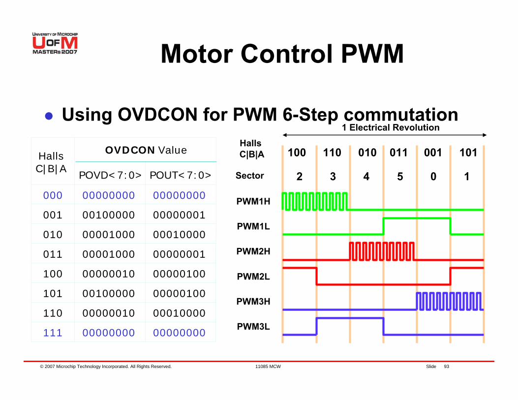
1 Electrical Revolution
Motor Control PWM
Using OVDCON for PWM 6-Step commutation
3 4 5 0 12
PWM1H
PWM1L
PWM2H
PWM2L
PWM3H
PWM3L
POVD<7:0> POUT<7:0>
00000000
00010000
00001000
00010000
00001000
00100000
00000001
00000100
OVDCON ValueHallsC|B|A
Sector
000 00000000
001 00000001
010
011
100
101
110
111
00000010
00100000 00000100
00000010
0000000000000000
110 010 011 001 101100Halls C|B|A
© 2007 Microchip Technology Incorporated. All Rights Reserved. 11085 MCW Slide 94
3-PhaseInverter BLDC6-Step
Generation
Main State Machine
Start /Stop
3-Phase Voltages
Hall Sensors
Angular Position
dsPIC30F+5V
Voltage
DutyCycles
GPI
O10
-bit
AD
C
CN
MC
PWM
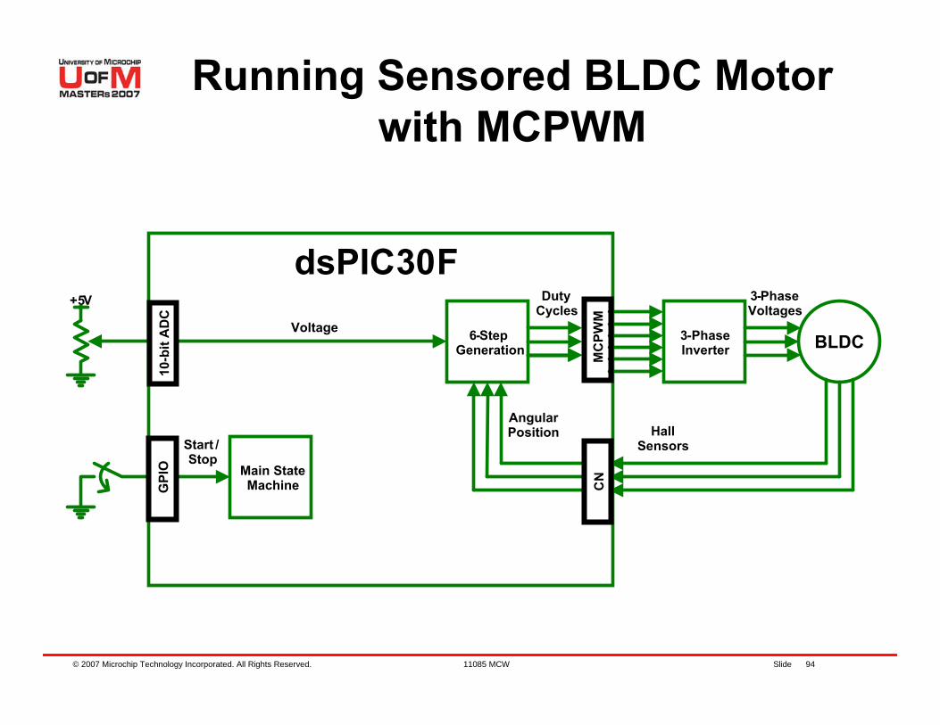
Running Sensored BLDC Motor with MCPWM
© 2007 Microchip Technology Incorporated. All Rights Reserved. 11085 MCW Slide 95
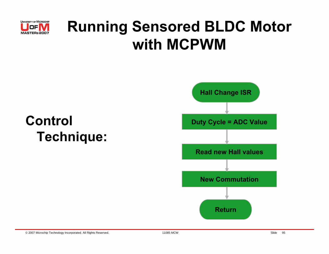
Control Technique:
Hall Change ISR
Duty Cycle = ADC Value
Read new Hall values
New Commutation
Return
Running Sensored BLDC Motor with MCPWM

© 2007 Microchip Technology Incorporated. All Rights Reserved. 11085 MCW Slide 96
Instructions for Lab 4:– Use workspace
“C:\RT301MCW\Lab4\Lab4.mcw”– Follow Lab 1 instructions to:
Compile codeProgram dsPIC® DSCRun code
Continued…
Lab 4 – Running BLDC Motor with MCPWM
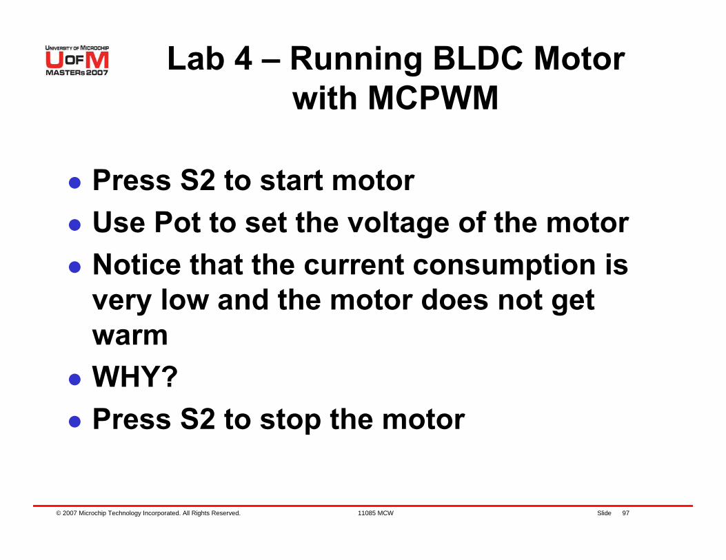
© 2007 Microchip Technology Incorporated. All Rights Reserved. 11085 MCW Slide 97
Press S2 to start motorUse Pot to set the voltage of the motorNotice that the current consumption is very low and the motor does not get warmWHY?Press S2 to stop the motor
Lab 4 – Running BLDC Motor with MCPWM
© 2007 Microchip Technology Incorporated. All Rights Reserved. 11085 MCW Slide 98
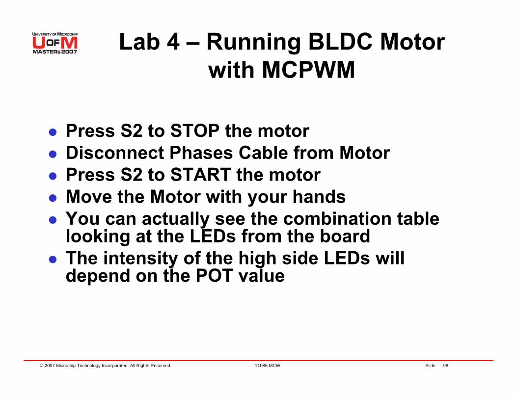
Press S2 to STOP the motorDisconnect Phases Cable from MotorPress S2 to START the motorMove the Motor with your handsYou can actually see the combination table looking at the LEDs from the boardThe intensity of the high side LEDs will depend on the POT value
Lab 4 – Running BLDC Motor with MCPWM
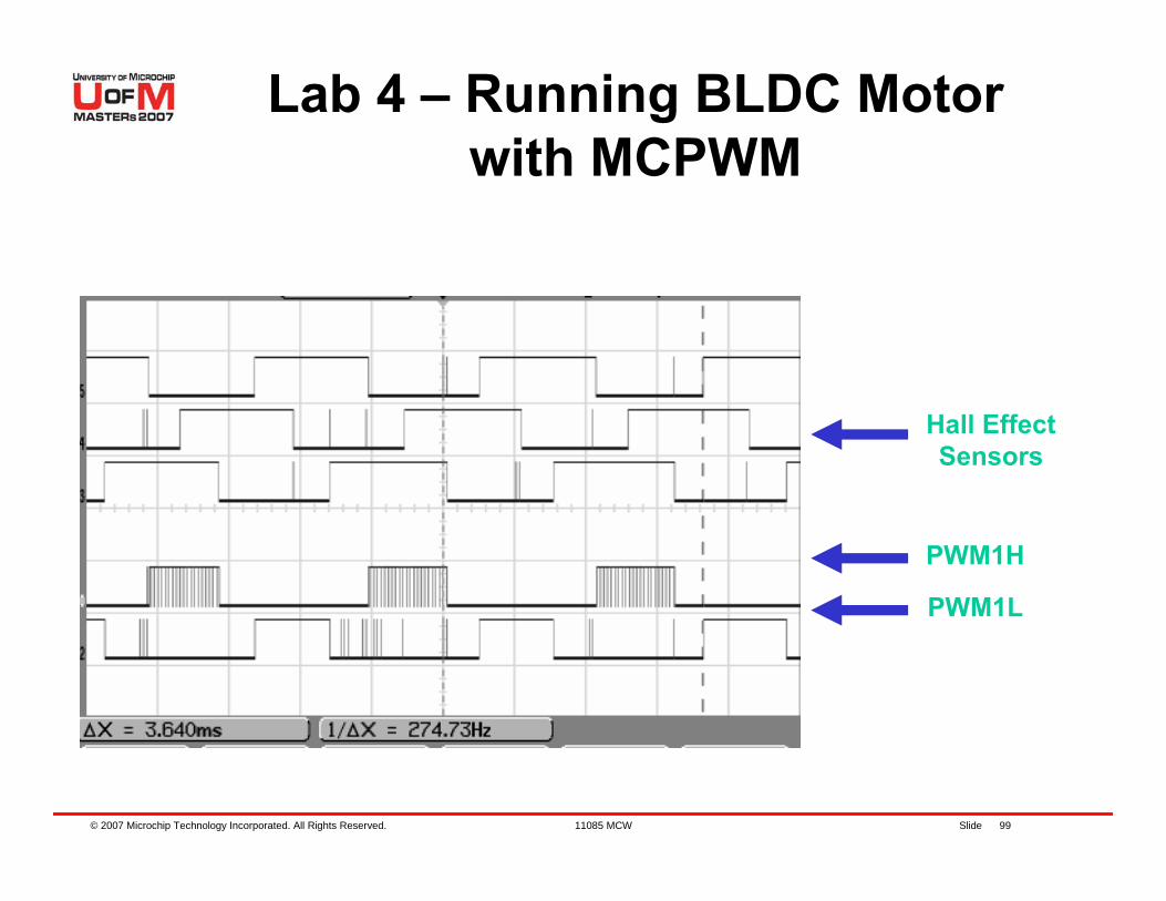
© 2007 Microchip Technology Incorporated. All Rights Reserved. 11085 MCW Slide 99
PWM1H
Hall EffectSensors
PWM1L
Lab 4 – Running BLDC Motor with MCPWM
© 2007 Microchip Technology Incorporated. All Rights Reserved. 11085 MCW Slide 100
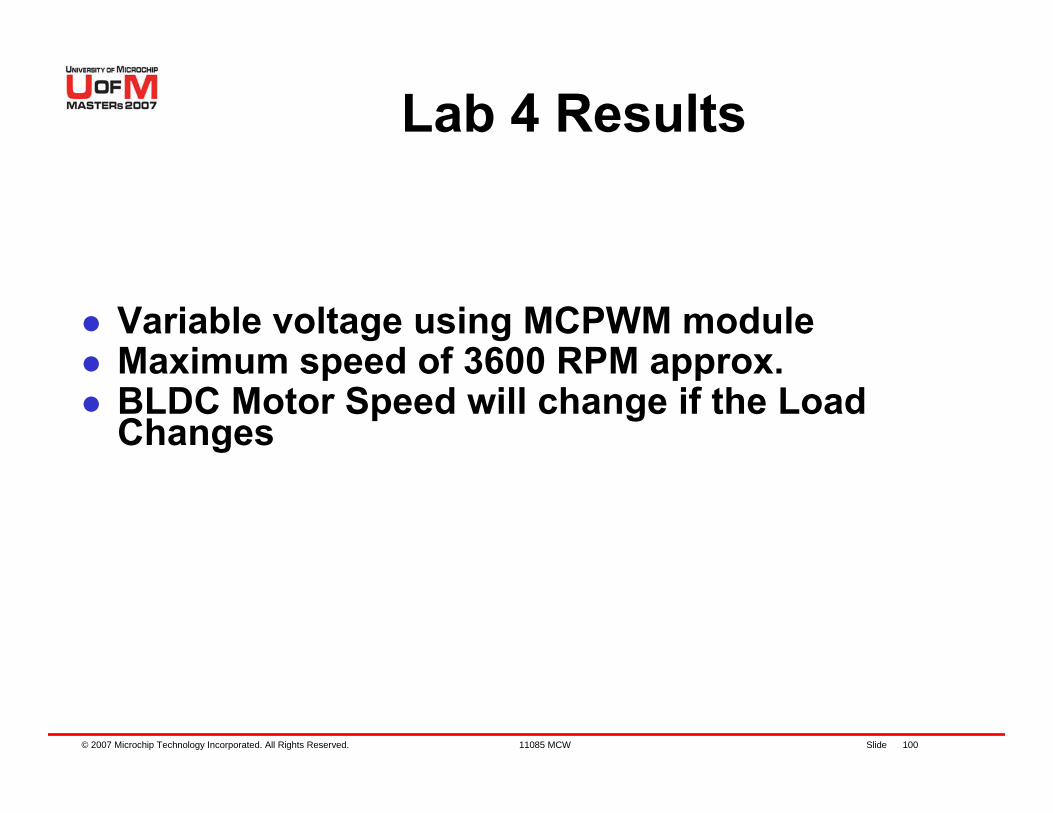
Variable voltage using MCPWM moduleMaximum speed of 3600 RPM approx.BLDC Motor Speed will change if the Load Changes
Lab 4 Results
© 2007 Microchip Technology Incorporated. All Rights Reserved. 11085 MCW Slide 101
Lab 5 – Running Closed-Loop BLDC
Motor
© 2007 Microchip Technology Incorporated. All Rights Reserved. 11085 MCW Slide 102
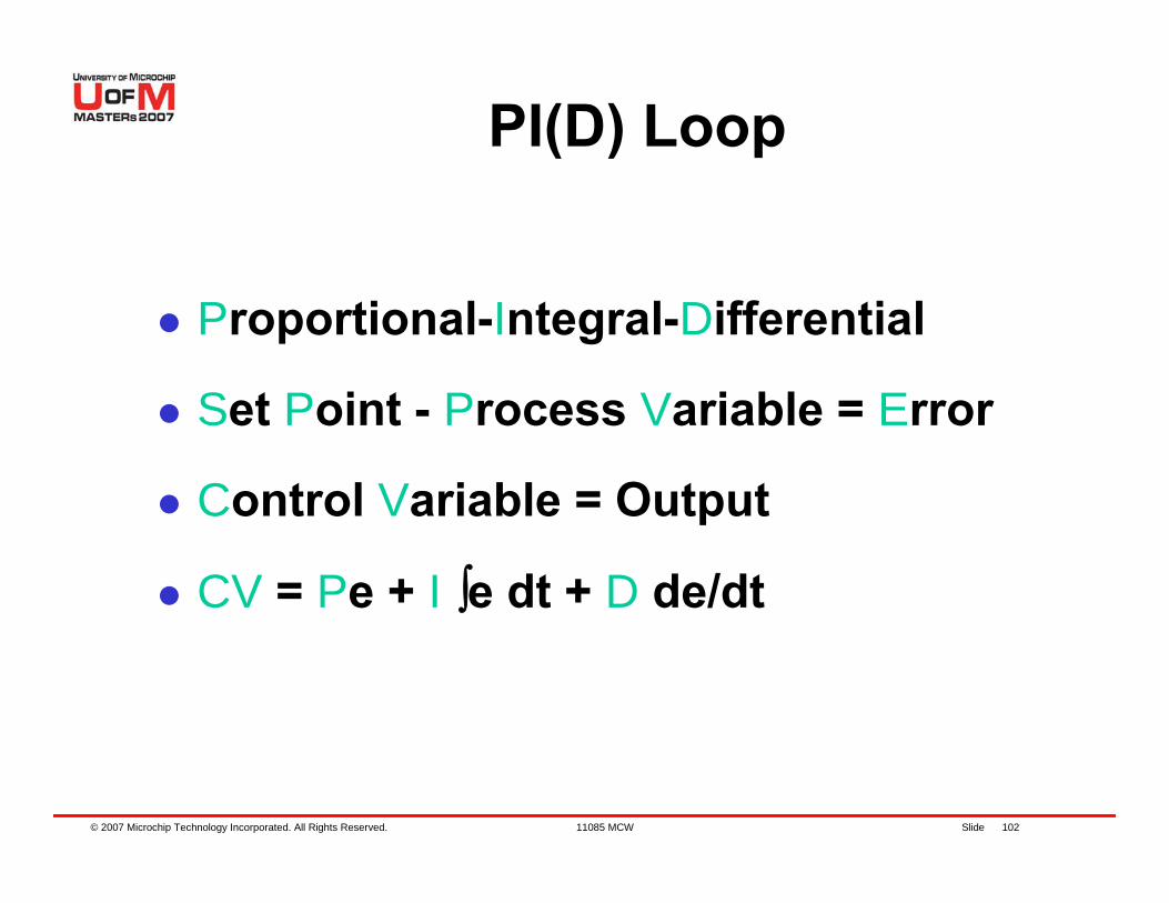
PI(D) Loop
Proportional-Integral-Differential
Set Point - Process Variable = Error
Control Variable = Output
CV = Pe + I ∫e dt + D de/dt
© 2007 Microchip Technology Incorporated. All Rights Reserved. 11085 MCW Slide 103
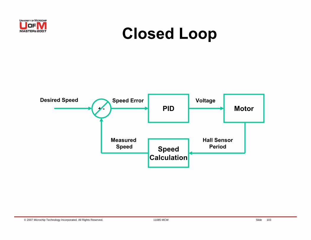
Closed Loop
PID Motor+ -Desired Speed
Measured Speed
Speed Error Voltage
SpeedCalculation
Hall SensorPeriod
© 2007 Microchip Technology Incorporated. All Rights Reserved. 11085 MCW Slide 104
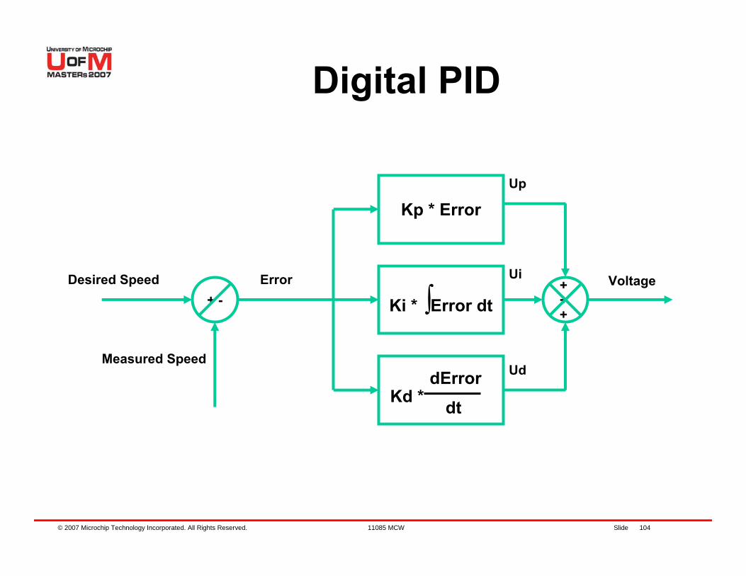
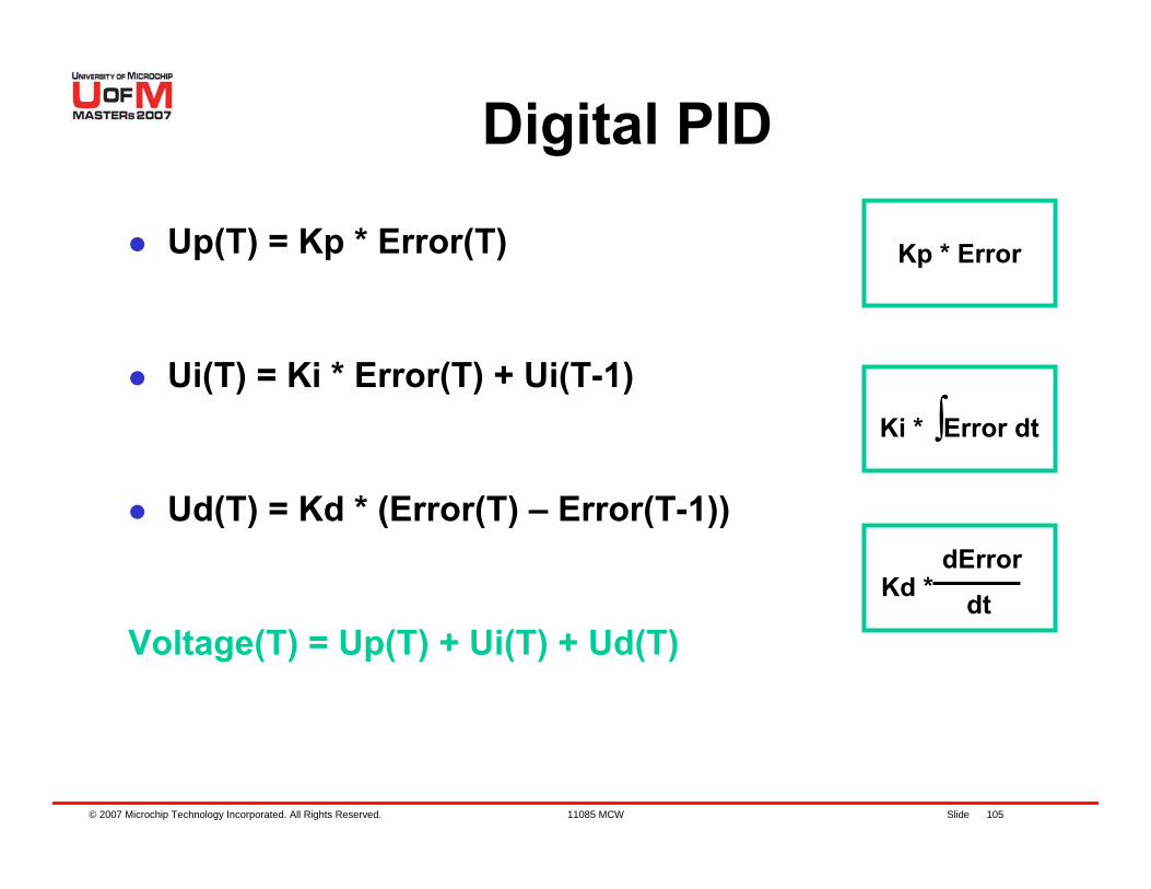
Digital PID
+ -Desired Speed
Measured Speed
Error Voltage
Kp * Error
+ +
Up
Ui
Ki * ∫Error dt
Kd *dError
dt
+
Ud
© 2007 Microchip Technology Incorporated. All Rights Reserved. 11085 MCW Slide 105
Digital PID
Up(T) = Kp * Error(T)
Ui(T) = Ki * Error(T) + Ui(T-1)
Ud(T) = Kd * (Error(T) – Error(T-1))
Voltage(T) = Up(T) + Ui(T) + Ud(T)
Kp * Error
Ki * ∫Error dt
Kd *dError
dt
© 2007 Microchip Technology Incorporated. All Rights Reserved. 11085 MCW Slide 106
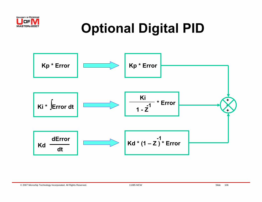
Optional Digital PID
Kp * Error
Ki * ∫Error dt
KddError
dt
Kp * Error
Kd * (1 – Z ) * Error-1
Ki
1 - Z-1 * Error +
+
+
© 2007 Microchip Technology Incorporated. All Rights Reserved. 11085 MCW Slide 107
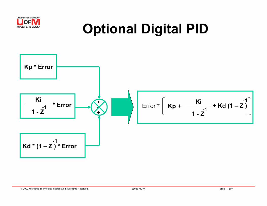
Optional Digital PID
Kp * Error
Kd * (1 – Z ) * Error-1
Ki
1 - Z-1 * Error +
+
+Error * Kp +
Ki
1 - Z-1 + Kd (1 – Z )
-1
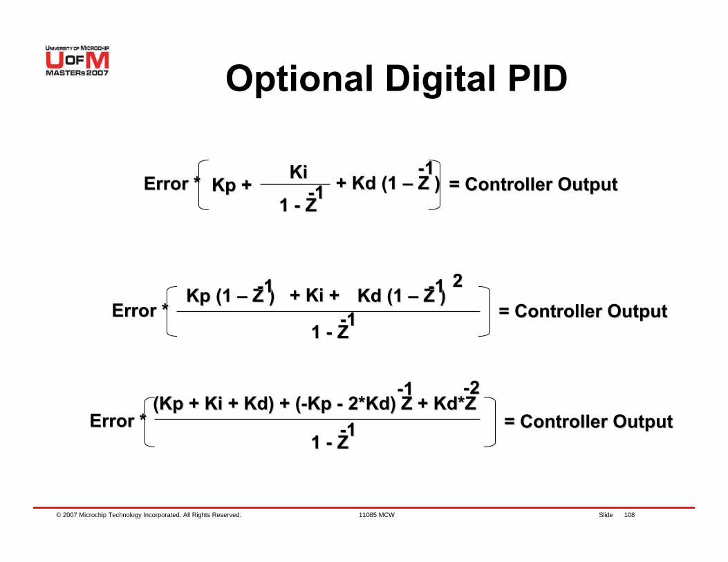
© 2007 Microchip Technology Incorporated. All Rights Reserved. 11085 MCW Slide 108
Optional Digital PID
Error *Error * KpKp ++KiKi
1 1 -- ZZ--11 + + KdKd (1 (1 –– Z )Z )
--11= Controller Output= Controller Output
Error *Error *1 1 -- ZZ-
-11 = Controller Output= Controller OutputKpKp (1 (1 –– Z )Z )--11 + + KiKi ++ KdKd (1 (1 –– Z )Z )--11 22
Error *Error *1 1 -- ZZ-
-11 = Controller Output= Controller Output((KpKp + + KiKi + + KdKd) + () + (--KpKp -- 2*2*KdKd) Z + ) Z + KdKd*Z*Z
--11 --22
© 2007 Microchip Technology Incorporated. All Rights Reserved. 11085 MCW Slide 109
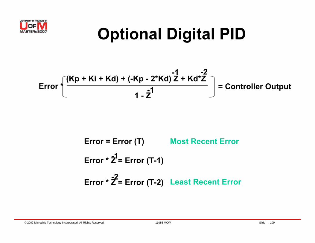
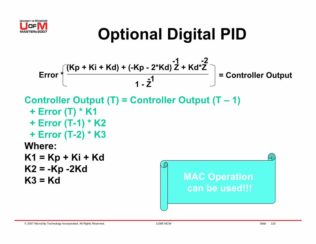
Optional Digital PID
Error *1 - Z-1
= Controller Output(Kp + Ki + Kd) + (-Kp - 2*Kd) Z + Kd*Z
-1 -2
Error = Error (T)
Error * Z = Error (T-1)
Error * Z = Error (T-2)-2
-1
Most Recent Error
Least Recent Error
© 2007 Microchip Technology Incorporated. All Rights Reserved. 11085 MCW Slide 110
Controller Output (T) = Controller Output (T – 1)+ Error (T) * K1 + Error (T-1) * K2 + Error (T-2) * K3
Where:K1 = Kp + Ki + KdK2 = -Kp -2KdK3 = Kd
Error *1 - Z-1
= Controller Output(Kp + Ki + Kd) + (-Kp - 2*Kd) Z + Kd*Z
-1 -2
MAC Operation can be used!!!
Optional Digital PID
© 2007 Microchip Technology Incorporated. All Rights Reserved. 11085 MCW Slide 111
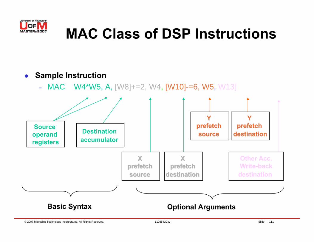
Sample Instruction– MAC W4*W5, A, [W8]+=2, W4, [W10]-=6, W5, W13]
Source operand registers
X X prefetch prefetch sourcesource
Y Y prefetch prefetch sourcesource
X X prefetch prefetch
destinationdestination
Y Y prefetch prefetch
destinationdestinationDestination accumulator
Optional Arguments
Other Acc.Write-backdestination
Basic Syntax
MAC Class of DSP Instructions
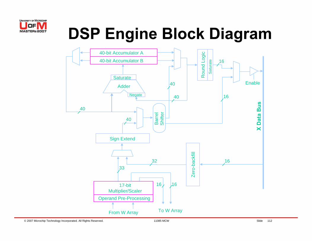
© 2007 Microchip Technology Incorporated. All Rights Reserved. 11085 MCW Slide 112
40-bit Accumulator A
40-bit Accumulator B
Adder
Saturate
Negate
Sign Extend
17-bit Multiplier/Scaler
Operand Pre-ProcessingZe
ro- b
a ck f
ill
Rou
n d L
ogi c
Satu
rate
Barr
e lSh
ifte r
From W Array
X D
a ta
Bu s
Enable
16
40
16
16
3233
40
40
40
To W Array
16 16
DSP Engine Block Diagram
© 2007 Microchip Technology Incorporated. All Rights Reserved. 11085 MCW Slide 113
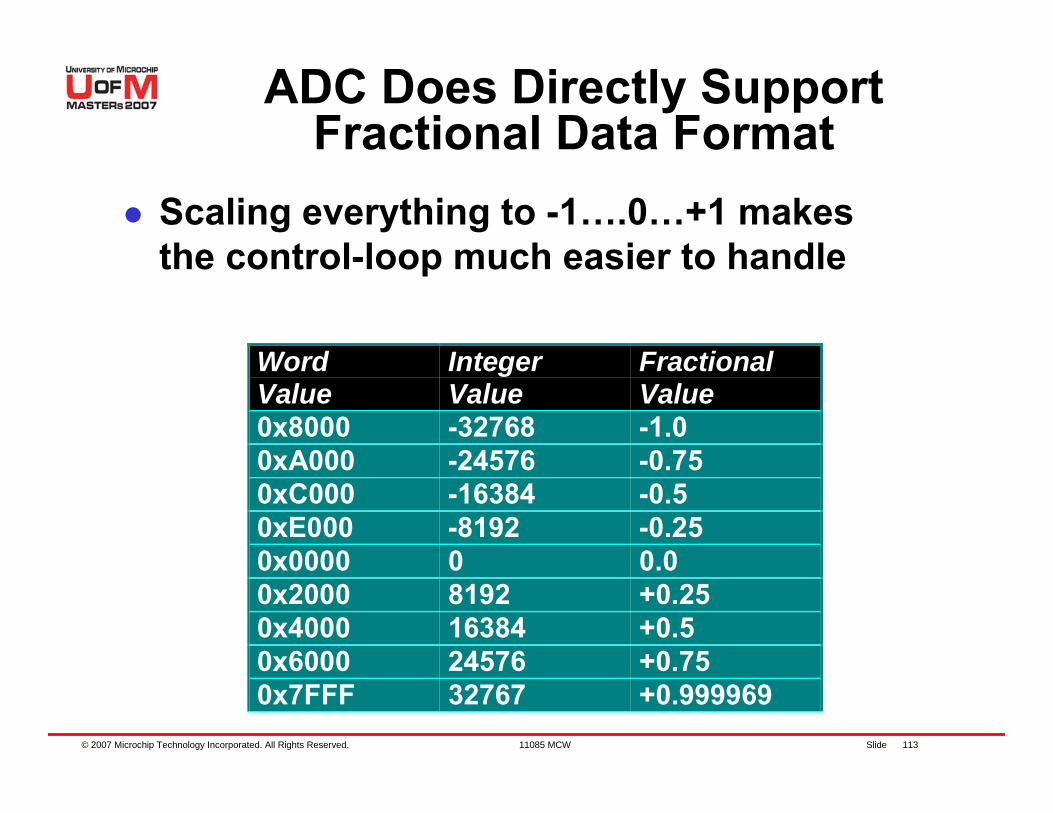
ADC Does Directly Support Fractional Data Format
Scaling everything to -1….0…+1 makesthe control-loop much easier to handle
WordValue
IntegerValue
FractionalValue
0x8000 -32768 -1.00xA000 -24576 -0.750xC000 -16384 -0.50xE000 -8192 -0.250x0000 0 0.00x2000 8192 +0.250x4000 16384 +0.50x6000 24576 +0.750x7FFF 32767 +0.999969
© 2007 Microchip Technology Incorporated. All Rights Reserved. 11085 MCW Slide 114
dsPIC® DSC has Input Capture inputs:– The period from the IC Channel is used to measure
the actual motor angular speed– Detect digital changes on a specific input pin (Hall
Sensor) and generates an interrupt– One of the Hall effect sensors is connected to an IC
Channel– When ICxInterrupt occurs, the period between IC
input transitions is buffered
Measuring Motor Speed with Input Capture (IC)
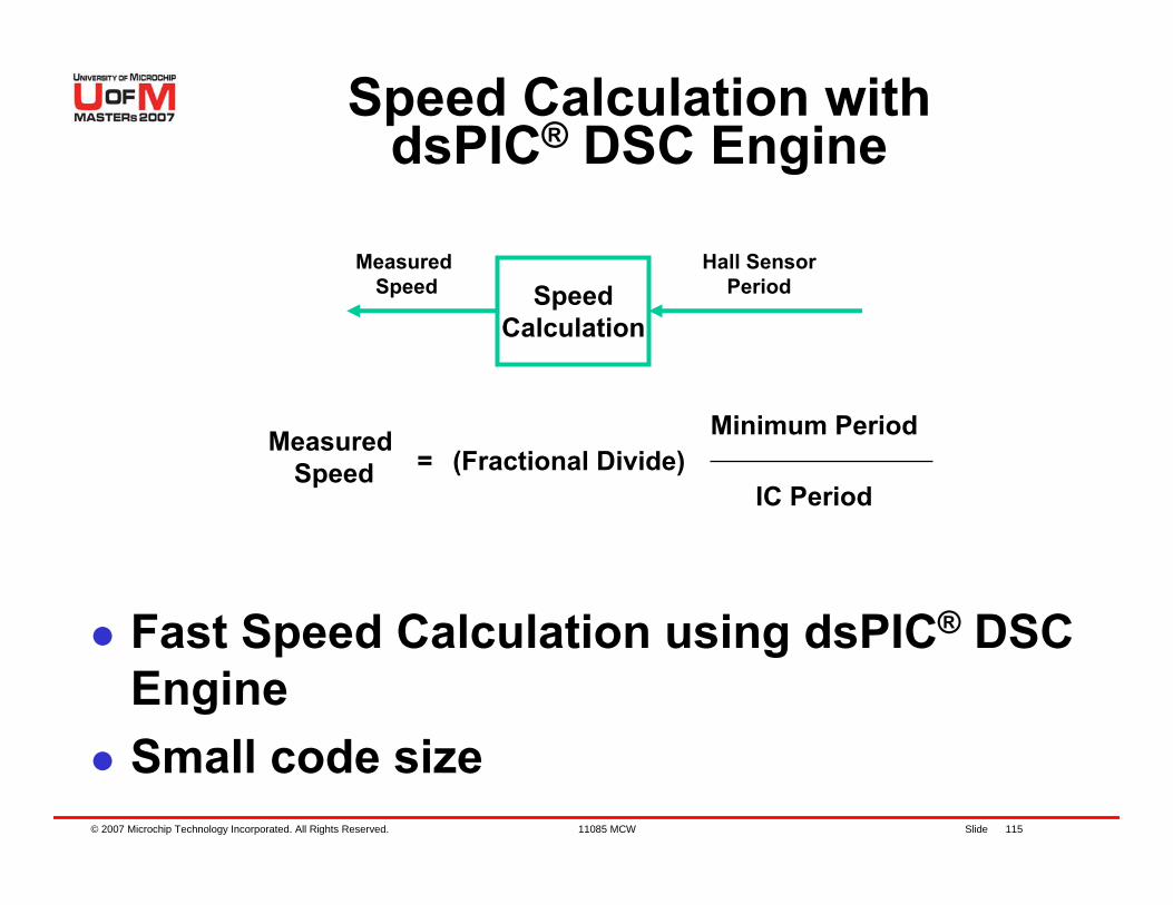
© 2007 Microchip Technology Incorporated. All Rights Reserved. 11085 MCW Slide 115
Measured Speed Speed
Calculation
Hall SensorPeriod
Measured Speed = (Fractional Divide)
Minimum Period
IC Period
Fast Speed Calculation using dsPIC® DSC EngineSmall code size
Speed Calculation with dsPIC® DSC Engine
© 2007 Microchip Technology Incorporated. All Rights Reserved. 11085 MCW Slide 116
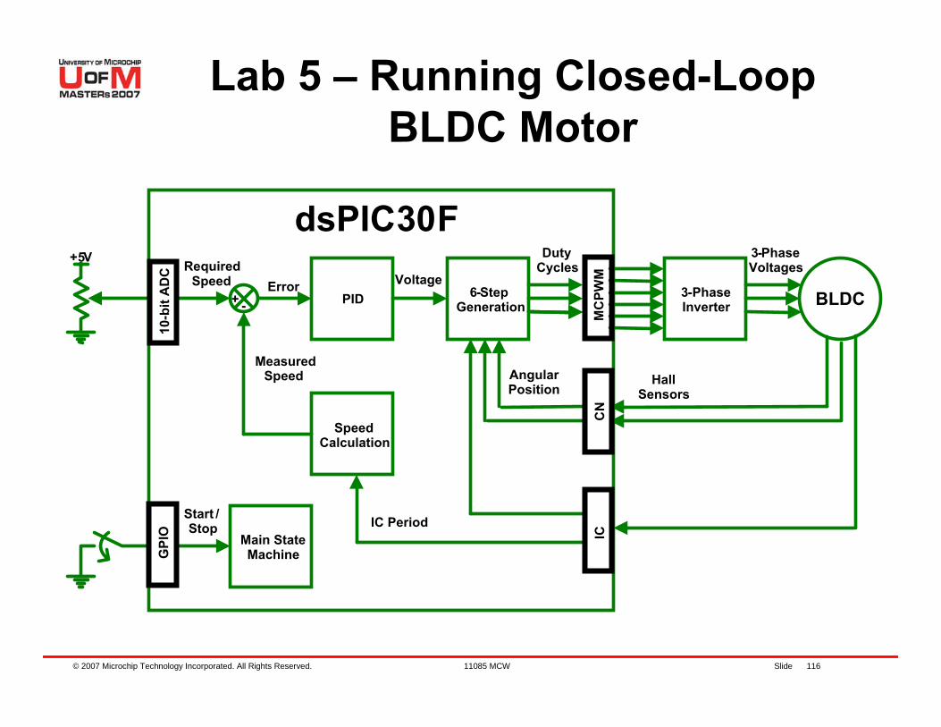
Lab 5 – Running Closed-Loop BLDC Motor
3-PhaseInverter BLDC6-Step
Generation
Main State Machine
Start /Stop
3-Phase Voltages
Hall Sensors
Angular Position
dsPIC30F+5V
RequiredSpeed
DutyCycles
+ - PIDError Voltage
SpeedCalculation
MeasuredSpeed
IC Period
10-b
it A
DC
G
PIO
MC
PWM
CN
IC
© 2007 Microchip Technology Incorporated. All Rights Reserved. 11085 MCW Slide 117
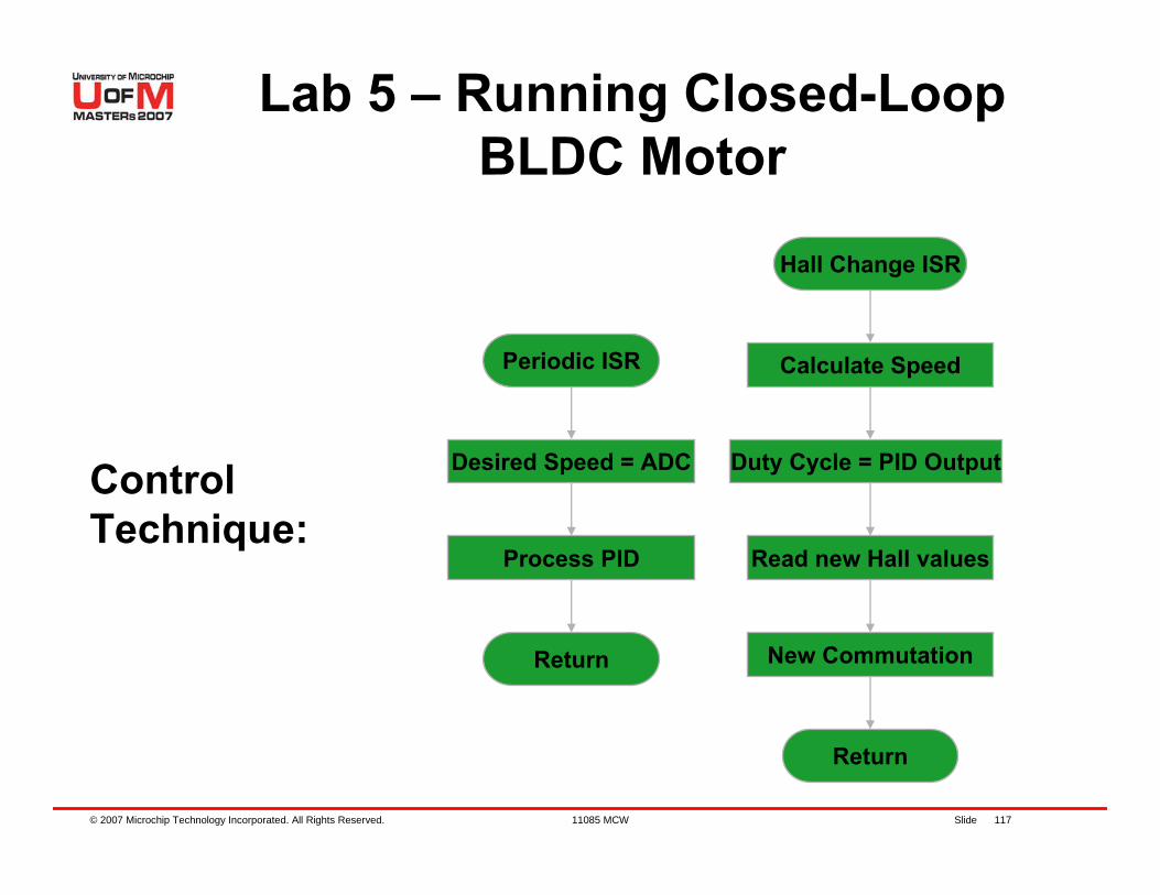
Control Technique:
Hall Change ISR
Calculate Speed
Read new Hall values
Duty Cycle = PID Output
Periodic ISR
Desired Speed = ADC
Return
Process PID
New Commutation
Return
Lab 5 – Running Closed-Loop BLDC Motor
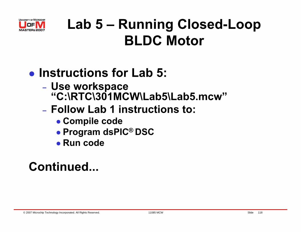
© 2007 Microchip Technology Incorporated. All Rights Reserved. 11085 MCW Slide 118
Instructions for Lab 5:– Use workspace
“C:\RTC\301MCW\Lab5\Lab5.mcw”– Follow Lab 1 instructions to:
Compile codeProgram dsPIC® DSC Run code
Continued...
Lab 5 – Running Closed-Loop BLDC Motor
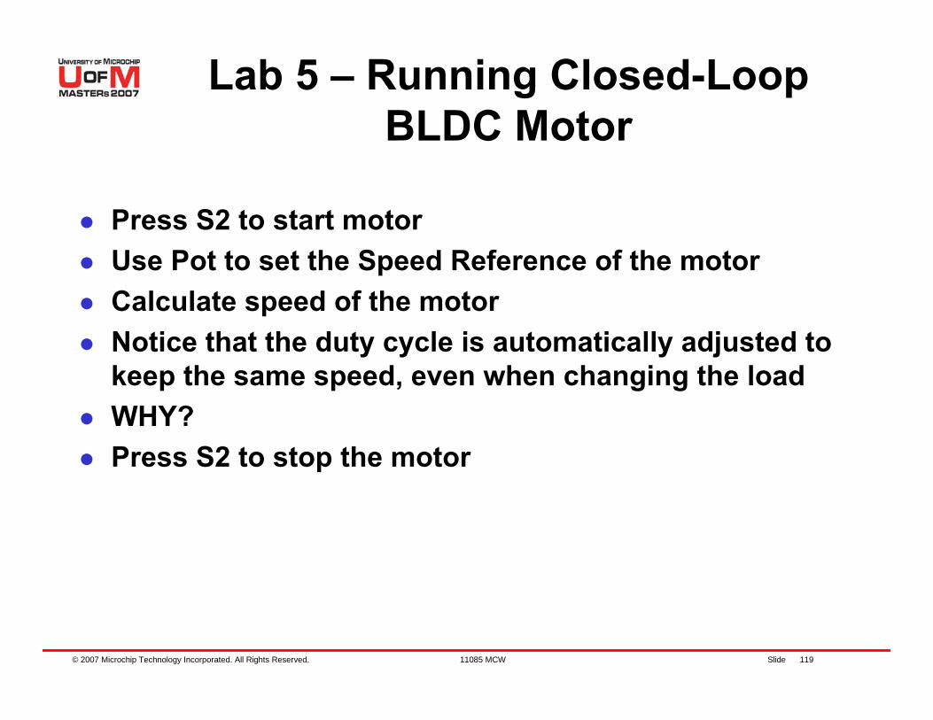
© 2007 Microchip Technology Incorporated. All Rights Reserved. 11085 MCW Slide 119
Press S2 to start motorUse Pot to set the Speed Reference of the motorCalculate speed of the motorNotice that the duty cycle is automatically adjusted to keep the same speed, even when changing the loadWHY?Press S2 to stop the motor
Lab 5 – Running Closed-Loop BLDC Motor
© 2007 Microchip Technology Incorporated. All Rights Reserved. 11085 MCW Slide 120
Lab 5 Results
Speed Control a Sensored BLDC motorImplementing a PID digital controller using DSP engine of a dsPIC® DSCUse dsPIC DSC’s PWM, OVDCON, CN and IC feature to control the speed of the BLDC motor
© 2007 Microchip Technology Incorporated. All Rights Reserved. 11085 MCW Slide 121
Lab 6 – Running Sinusoidal BLDC
Motor
© 2007 Microchip Technology Incorporated. All Rights Reserved. 11085 MCW Slide 122
Lab 6 – Running Sinusoidal BLDC Motor
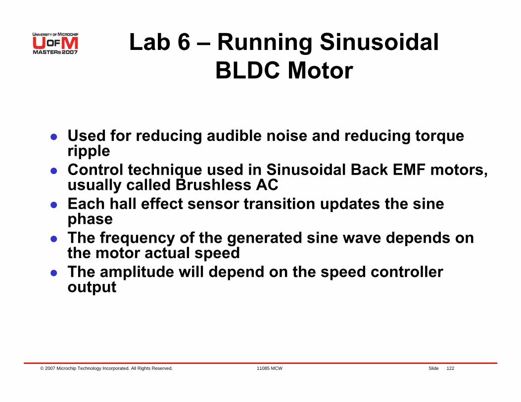
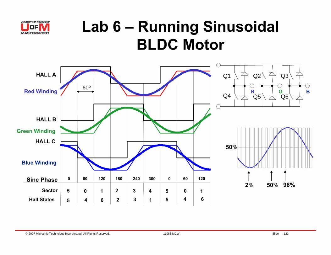
Used for reducing audible noise and reducing torque rippleControl technique used in Sinusoidal Back EMF motors, usually called Brushless ACEach hall effect sensor transition updates the sine phaseThe frequency of the generated sine wave depends on the motor actual speedThe amplitude will depend on the speed controller output
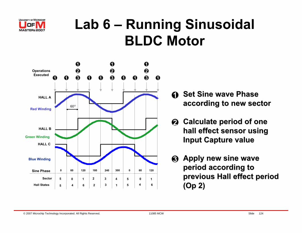
© 2007 Microchip Technology Incorporated. All Rights Reserved. 11085 MCW Slide 123
R G
Q1 Q3Q2
Q4 Q6Q5
Sine Phase
B
Green Winding
60 120 180 240 300 0
60o
HALL A
HALL B
HALL C
60 1200
Sector 5
Hall States0 1 2
5 4 6 2
3
34
1
55
04
16
Blue Winding
Red Winding
2% 50% 98%
50%
Lab 6 – Running Sinusoidal BLDC Motor
© 2007 Microchip Technology Incorporated. All Rights Reserved. 11085 MCW Slide 124
Sine Phase
Green Winding
60 120 180 240 300 0
60o
HALL A
HALL B
HALL C
60 1200
Sector 5
Hall States
0 1 2
5 4 6 2
3
3
4
1
5
5
0
4
1
6
Blue Winding
Red Winding
1 1
123
123
1231 1 1 1 1
1
2
3
OperationsExecuted
Set Sine wave Phase Set Sine wave Phase according to new sectoraccording to new sector
Calculate period of one Calculate period of one hall effect sensor using hall effect sensor using Input Capture valueInput Capture value
Apply new sine wave Apply new sine wave period according to period according to previous Hall effect period previous Hall effect period (Op 2)(Op 2)
Lab 6 – Running Sinusoidal BLDC Motor
© 2007 Microchip Technology Incorporated. All Rights Reserved. 11085 MCW Slide 125
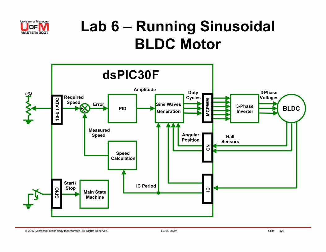
3-PhaseInverter BLDCGeneration
Main State Machine
Start /Stop
3-Phase Voltages
Hall Sensors
Angular Position
dsPIC30F+5V
RequiredSpeed
DutyCycles
+ - PIDError
Amplitude
SpeedCalculation
MeasuredSpeed
IC Period
10-b
it A
DC
G
PIO
MC
PWM
CN
IC
Sine Waves
Lab 6 – Running Sinusoidal BLDC Motor
© 2007 Microchip Technology Incorporated. All Rights Reserved. 11085 MCW Slide 126
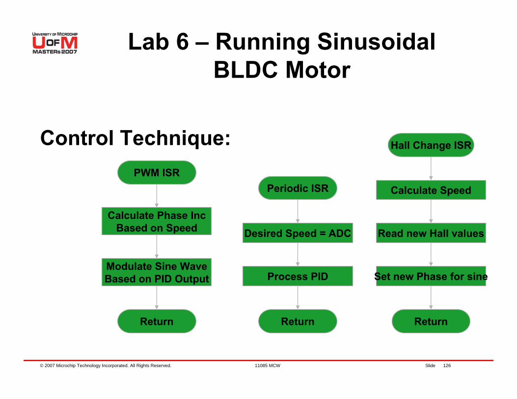
Control Technique: Hall Change ISR
Calculate Speed
Read new Hall values
Periodic ISR
Desired Speed = ADC
Return
Process PID Set new Phase for sine
Return
PWM ISR
Calculate Phase IncBased on Speed
Return
Modulate Sine WaveBased on PID Output
Lab 6 – Running Sinusoidal BLDC Motor
© 2007 Microchip Technology Incorporated. All Rights Reserved. 11085 MCW Slide 127
Instructions for Lab 6:– Use workspace “C:\WIB\Lab6\Lab6.mcw”– Follow Lab 1 instructions to:
Compile codeProgram dsPIC® DSC Run code
Continued...
Lab 6 – Running Sinusoidal BLDC Motor
© 2007 Microchip Technology Incorporated. All Rights Reserved. 11085 MCW Slide 128
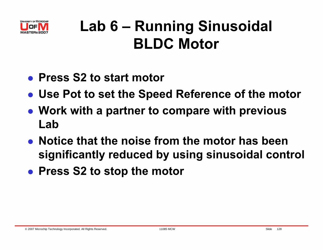
Press S2 to start motorUse Pot to set the Speed Reference of the motorWork with a partner to compare with previous LabNotice that the noise from the motor has been significantly reduced by using sinusoidal controlPress S2 to stop the motor
Lab 6 – Running Sinusoidal BLDC Motor
© 2007 Microchip Technology Incorporated. All Rights Reserved. 11085 MCW Slide 129
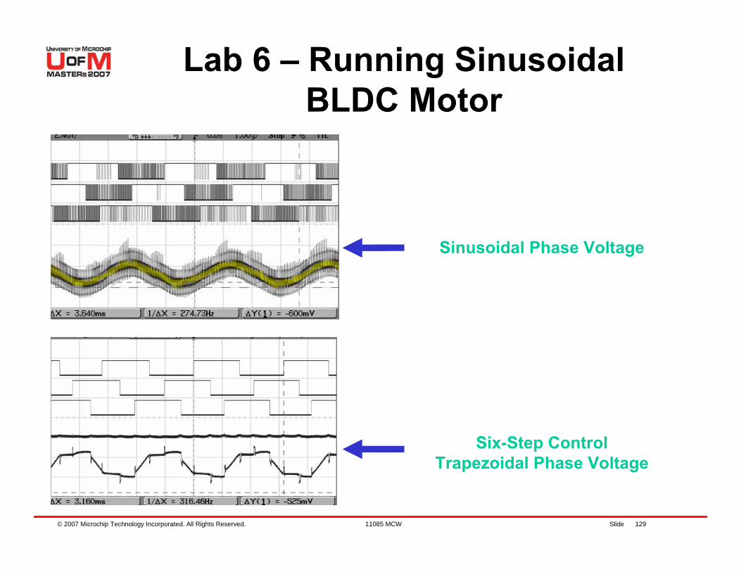
Six-Step ControlTrapezoidal Phase Voltage
Sinusoidal Phase Voltage
Lab 6 – Running Sinusoidal BLDC Motor
© 2007 Microchip Technology Incorporated. All Rights Reserved. 11085 MCW Slide 130
Sinusoidal control of a BLDC motorReduced audible noiseReduced torque rippleCE003. Driving a BLDC with Sinusoidal Voltages using dsPIC30F.
Lab 6 Results
© 2007 Microchip Technology Incorporated. All Rights Reserved. 11085 MCW Slide 131
Lab 7 – BLDC Operation with Phase
Advance
© 2007 Microchip Technology Incorporated. All Rights Reserved. 11085 MCW Slide 132
Drive voltages are shifted (Phase advanced) compared to back EMFPhase advance will produce an increase in the stator field, which increases the speed of the motorPhase shift will produce a negative field on the rotor, which will reduce the overall torque available in the motorFor light loads, the speed is significantly increased using phase advance, sacrificing full load torque, efficiency and audible noise
Lab 7 – BLDC Operation with Phase Advance
© 2007 Microchip Technology Incorporated. All Rights Reserved. 11085 MCW Slide 133
Consists of commutating the motor before the next hall effect sensor transition has occurredKnowing the motor speed, we can schedule a commutation with a timer, before the next hall effect sensor interrupt occursPhase advance technique substantially increases speed rangeIt also helps to compensate misalignments on the hall effect sensor
Lab 7 – BLDC Operation with Phase Advance
© 2007 Microchip Technology Incorporated. All Rights Reserved. 11085 MCW Slide 134
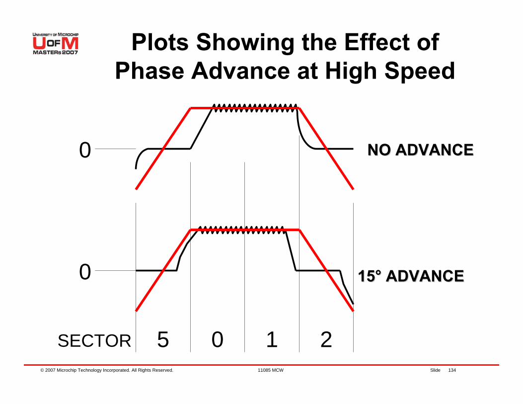
NO ADVANCENO ADVANCE
1515°° ADVANCEADVANCE
5 0 1 2SECTOR
0
0
Plots Showing the Effect of Phase Advance at High Speed
© 2007 Microchip Technology Incorporated. All Rights Reserved. 11085 MCW Slide 135
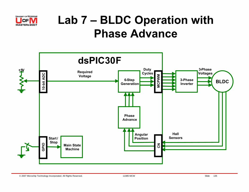
3-PhaseInverter BLDC6-Step
Generation
Main State Machine
Start /Stop
3-Phase Voltages
Hall Sensors
Angular Position
dsPIC30F+5V Duty
Cycles
Phase Advance
Required Voltage
10-b
it A
DC
G
PIO
MC
PWM
CN
Lab 7 – BLDC Operation with Phase Advance
© 2007 Microchip Technology Incorporated. All Rights Reserved. 11085 MCW Slide 136
Control Technique:
Hall Change ISR
Calculate Speed
Schedule ISR Based onActual Speed
Return
Duty Cycle = ADC
Save Hall values
Scheduled ISR
New Commutation, Actual Sector + 1
Return
Load saved Hall values
Predict new Hall values
Lab 7 – BLDC Operation with Phase Advance
© 2007 Microchip Technology Incorporated. All Rights Reserved. 11085 MCW Slide 137
Instructions for Lab 7:– Use workspace
“C:\RTC\301MCW\Lab7\Lab7.mcw”– Follow Lab 1 instructions to:
Compile codeProgram dsPIC® DSC Run code
Continued...
Lab 7 – BLDC Operation with Phase Advance
© 2007 Microchip Technology Incorporated. All Rights Reserved. 11085 MCW Slide 138
Press S2 to start motorUse Pot to set the Voltage applied to the motorNotice that the maximum speed of the motor is extended using Phase AdvanceAlthough, the motor is very noisy and current consumption is higherWHY?Press S2 to stop the motor
Lab 7 – BLDC Operation with Phase Advance
© 2007 Microchip Technology Incorporated. All Rights Reserved. 11085 MCW Slide 139
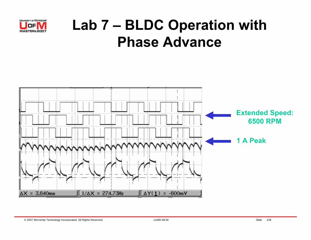
1 A Peak
Extended Speed:6500 RPM
Lab 7 – BLDC Operation with Phase Advance
© 2007 Microchip Technology Incorporated. All Rights Reserved. 11085 MCW Slide 140
Details of Program
Use MPLAB® IDE to go thru sections of the code
© 2007 Microchip Technology Incorporated. All Rights Reserved. 11085 MCW Slide 141
Phase advance controlExtended speed range of up to 70% (motor dependent)Trade-off, current consumption and audible noise
Lab 7 Results
© 2007 Microchip Technology Incorporated. All Rights Reserved. 11085 MCW Slide 142
Sensorless BLDC Motor
© 2007 Microchip Technology Incorporated. All Rights Reserved. 11085 MCW Slide 143
Why Sensorless?
Reliability – especially aerospace, militaryPhysical space restrictions – axial lengthIssues surrounding sealing of connectionsApplications where rotor runs “flooded”Manufacturability – alignment and duty cycle toleranceCost – especially on low power systems– Even at high volumes, position sensing can add $3 to
system cost
© 2007 Microchip Technology Incorporated. All Rights Reserved. 11085 MCW Slide 144
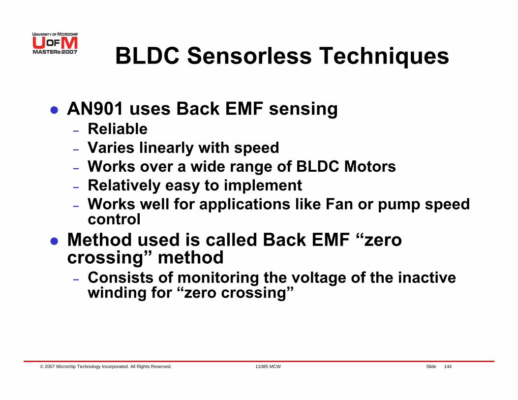
BLDC Sensorless Techniques
AN901 uses Back EMF sensing– Reliable– Varies linearly with speed – Works over a wide range of BLDC Motors– Relatively easy to implement– Works well for applications like Fan or pump speed
controlMethod used is called Back EMF “zero crossing” method– Consists of monitoring the voltage of the inactive
winding for “zero crossing”
© 2007 Microchip Technology Incorporated. All Rights Reserved. 11085 MCW Slide 145
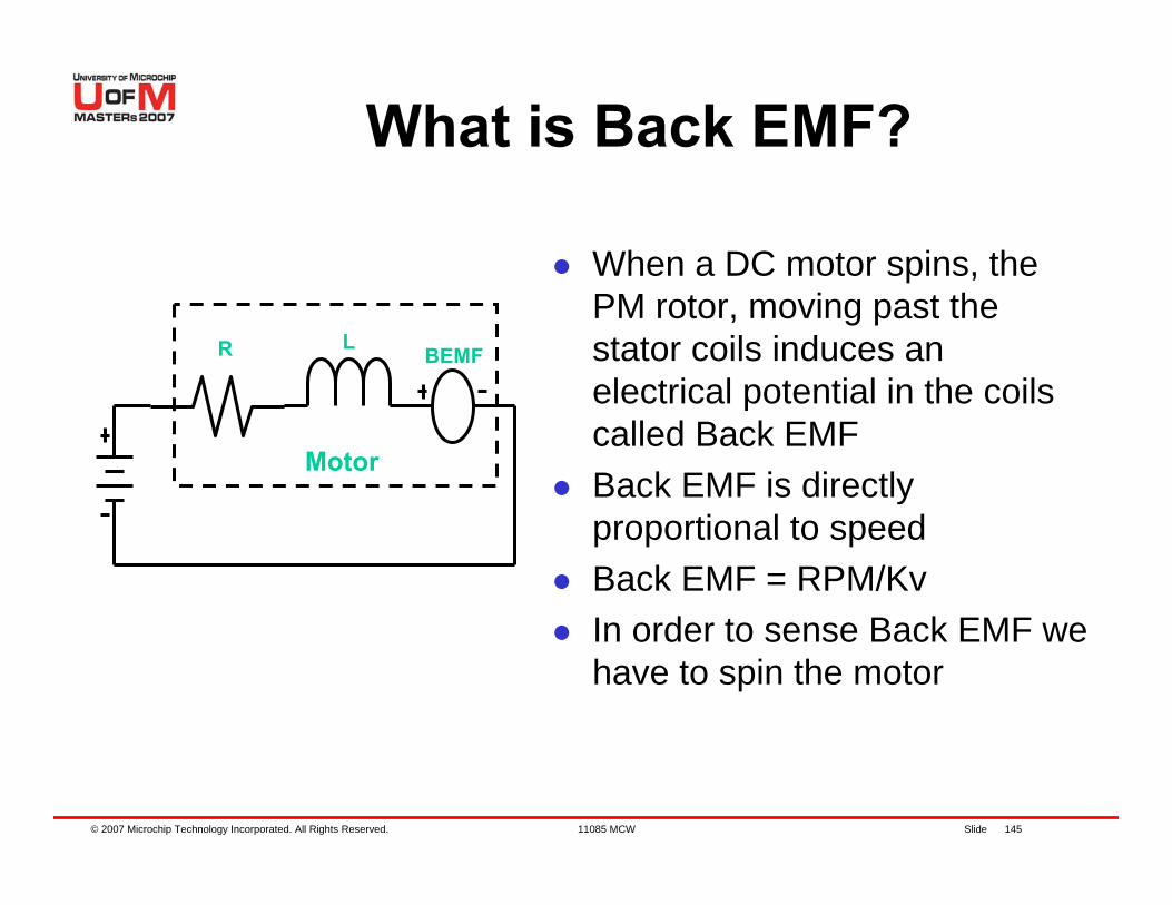
What is Back EMF?
When a DC motor spins, the PM rotor, moving past the stator coils induces an electrical potential in the coils called Back EMFBack EMF is directly proportional to speedBack EMF = RPM/KvIn order to sense Back EMF we have to spin the motor
BEMF
Motor
R L
© 2007 Microchip Technology Incorporated. All Rights Reserved. 11085 MCW Slide 146
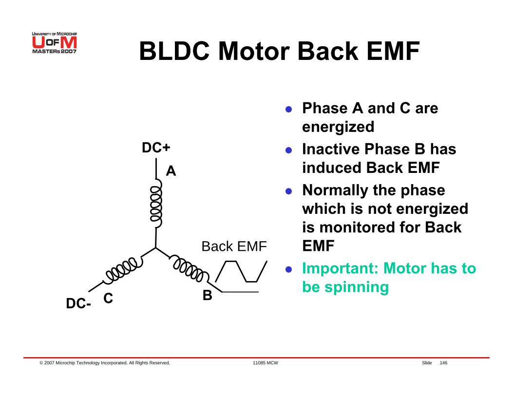
BLDC Motor Back EMF
A
C B
DC+
DC-
Back EMF
Phase A and C are energizedInactive Phase B has induced Back EMFNormally the phase which is not energized is monitored for Back EMFImportant: Motor has to be spinning
© 2007 Microchip Technology Incorporated. All Rights Reserved. 11085 MCW Slide 147
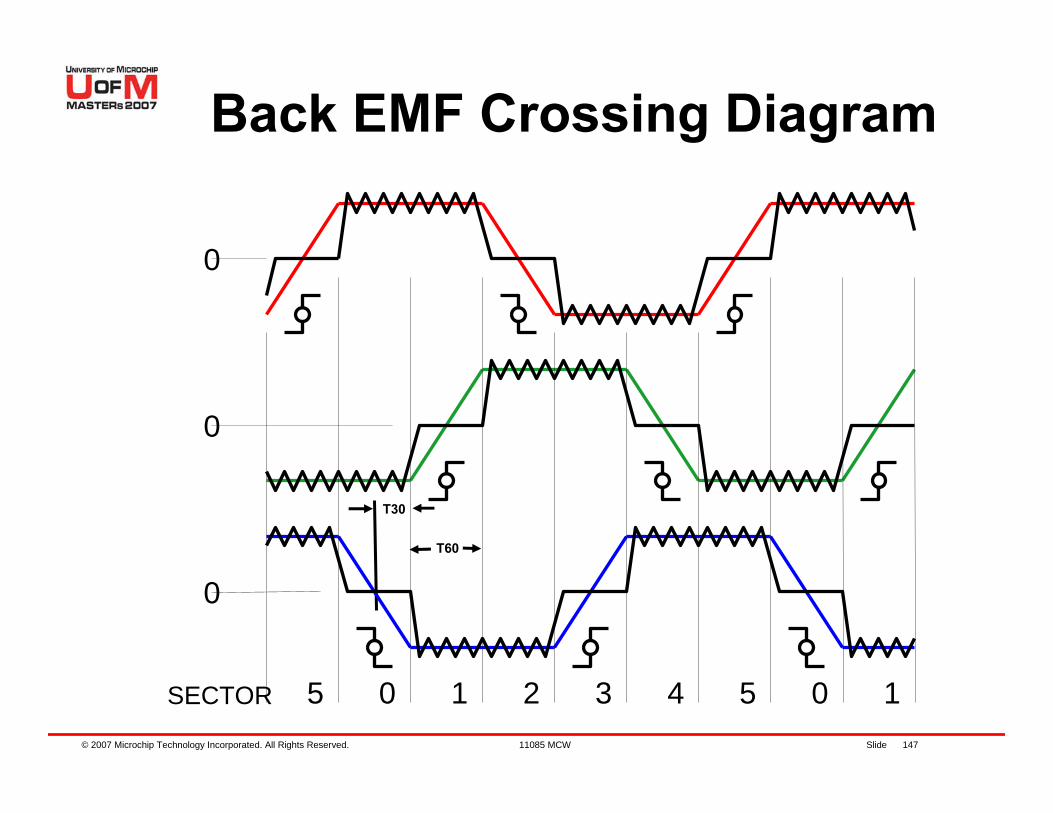
T30
T60
5 0 1 2 3 4 5 0 1SECTOR
0
0
0
Back EMF Crossing Diagram
© 2007 Microchip Technology Incorporated. All Rights Reserved. 11085 MCW Slide 148
In every electrical cycle, there are periods when each phase is not being drivenDuring these regions one end of the inactive phase is referenced to the star point and the other is monitoredThe monitored voltage will cross the 1/2 VDD point at 30 electrical degreesKnowing the last “zero crossing” time we know the 60 electrical degree time (T60)T60 divided by 2 = T30 is loaded in TMR2The ISR of TMR2 then commutes the next pair of windings at T30 seconds later
The Back EMF “zero crossing”method in detail
© 2007 Microchip Technology Incorporated. All Rights Reserved. 11085 MCW Slide 149
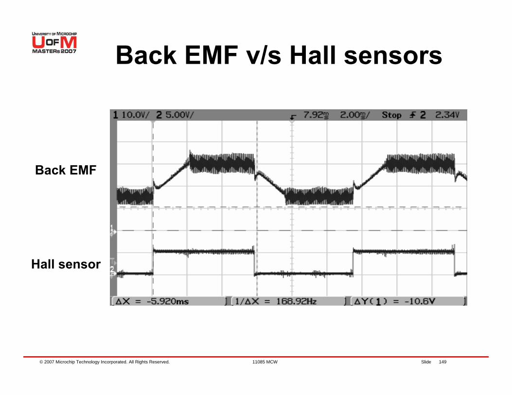
Back EMF v/s Hall sensors
Back EMF
Hall sensor
© 2007 Microchip Technology Incorporated. All Rights Reserved. 11085 MCW Slide 150
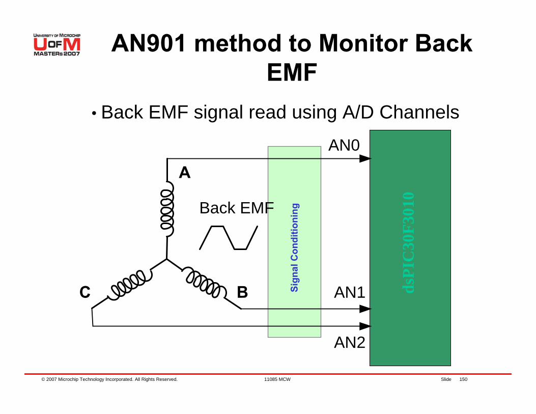
• Back EMF signal read using A/D Channels
Sign
al C
ondi
tioni
ng
dsPI
C30
F301
0
AN901 method to Monitor Back EMF
A
C B
AN0
AN1
AN2
Back EMF
© 2007 Microchip Technology Incorporated. All Rights Reserved. 11085 MCW Slide 151
How to “Start Spinning”
The motor is energized Open Loop (no feedback)The speed is ramped up to a programmable valueAt a given time two winding are energized. The third is monitored for Back EMFThe unexcited windings are then monitored for two rising edges (120° information)From the time and sequencing of the edges we can determine the speed and rotation directionThe BEMF sensing algorithm is now applied to rotate the motor
© 2007 Microchip Technology Incorporated. All Rights Reserved. 11085 MCW Slide 152
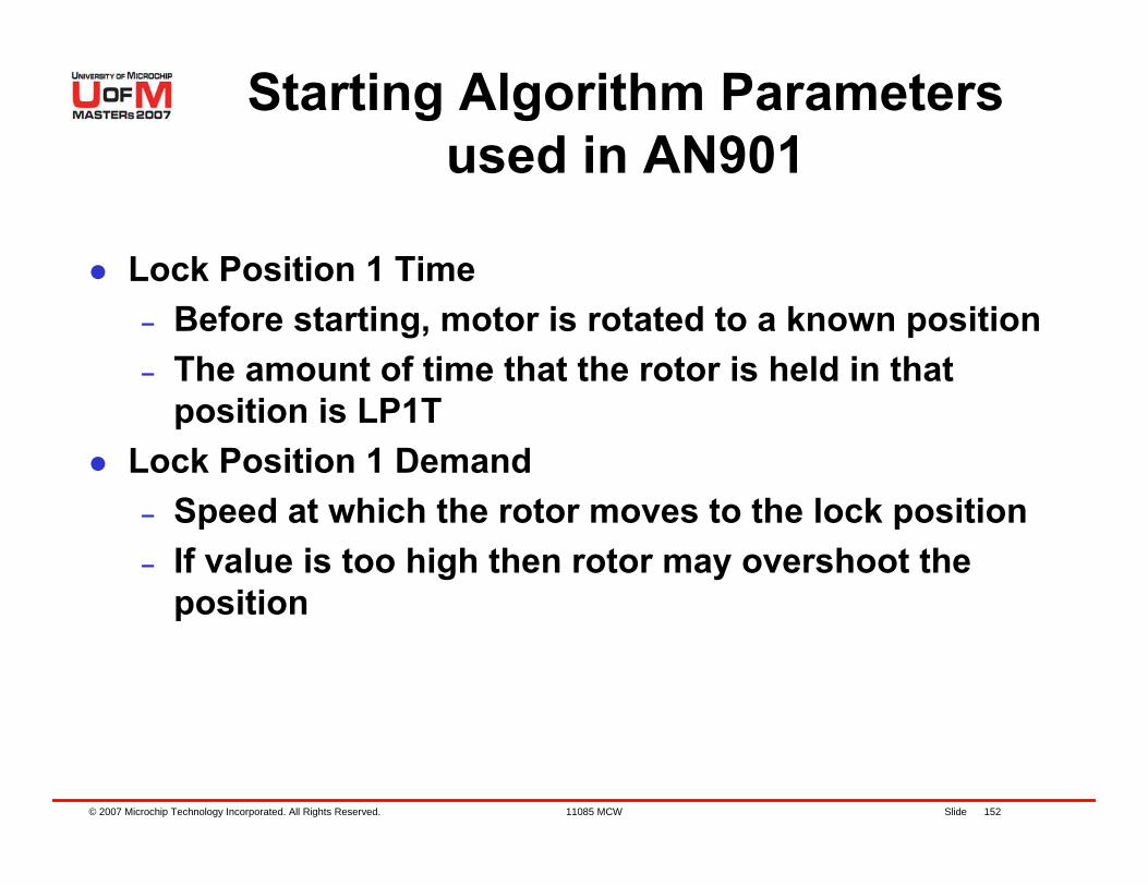
Lock Position 1 Time– Before starting, motor is rotated to a known position– The amount of time that the rotor is held in that
position is LP1TLock Position 1 Demand– Speed at which the rotor moves to the lock position– If value is too high then rotor may overshoot the
position
Starting Algorithm Parameters used in AN901
© 2007 Microchip Technology Incorporated. All Rights Reserved. 11085 MCW Slide 153
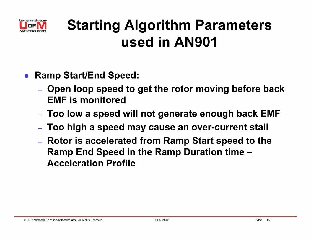
Ramp Start/End Speed:– Open loop speed to get the rotor moving before back
EMF is monitored– Too low a speed will not generate enough back EMF– Too high a speed may cause an over-current stall– Rotor is accelerated from Ramp Start speed to the
Ramp End Speed in the Ramp Duration time –Acceleration Profile
Starting Algorithm Parameters used in AN901
© 2007 Microchip Technology Incorporated. All Rights Reserved. 11085 MCW Slide 154
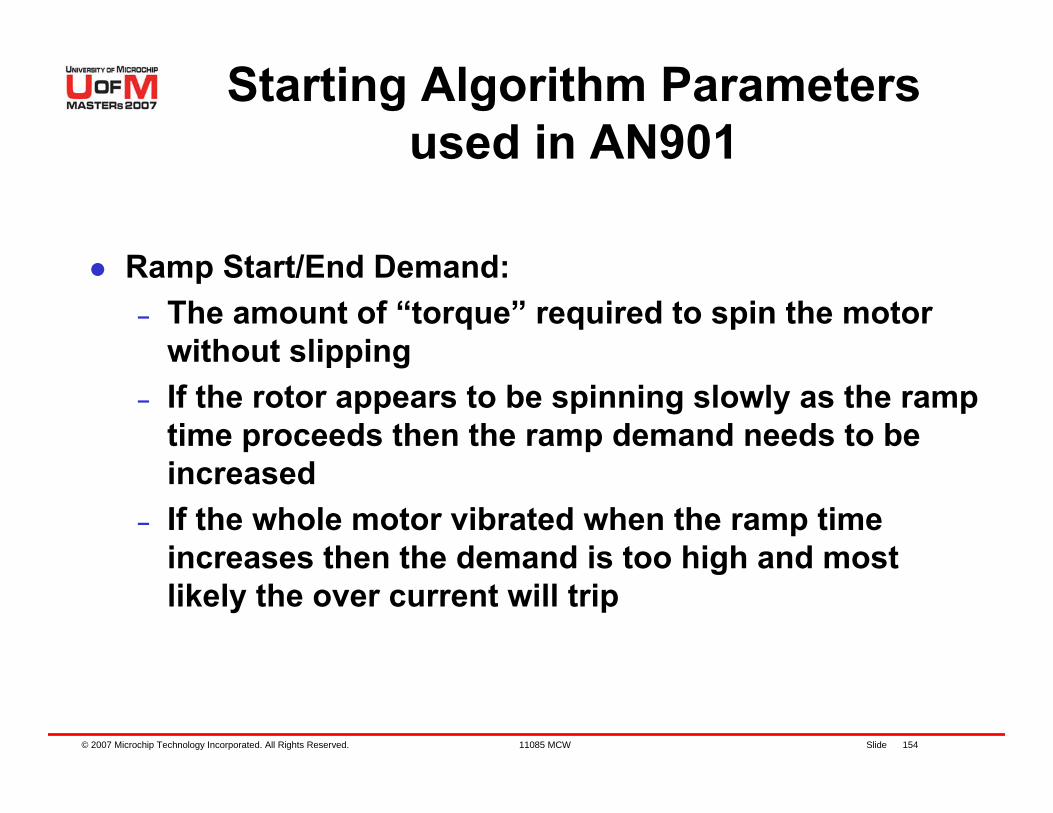
Ramp Start/End Demand:– The amount of “torque” required to spin the motor
without slipping– If the rotor appears to be spinning slowly as the ramp
time proceeds then the ramp demand needs to be increased
– If the whole motor vibrated when the ramp time increases then the demand is too high and most likely the over current will trip
Starting Algorithm Parameters used in AN901
© 2007 Microchip Technology Incorporated. All Rights Reserved. 11085 MCW Slide 155
Lab 8 – Running Sensorless BLDC Motor
© 2007 Microchip Technology Incorporated. All Rights Reserved. 11085 MCW Slide 156
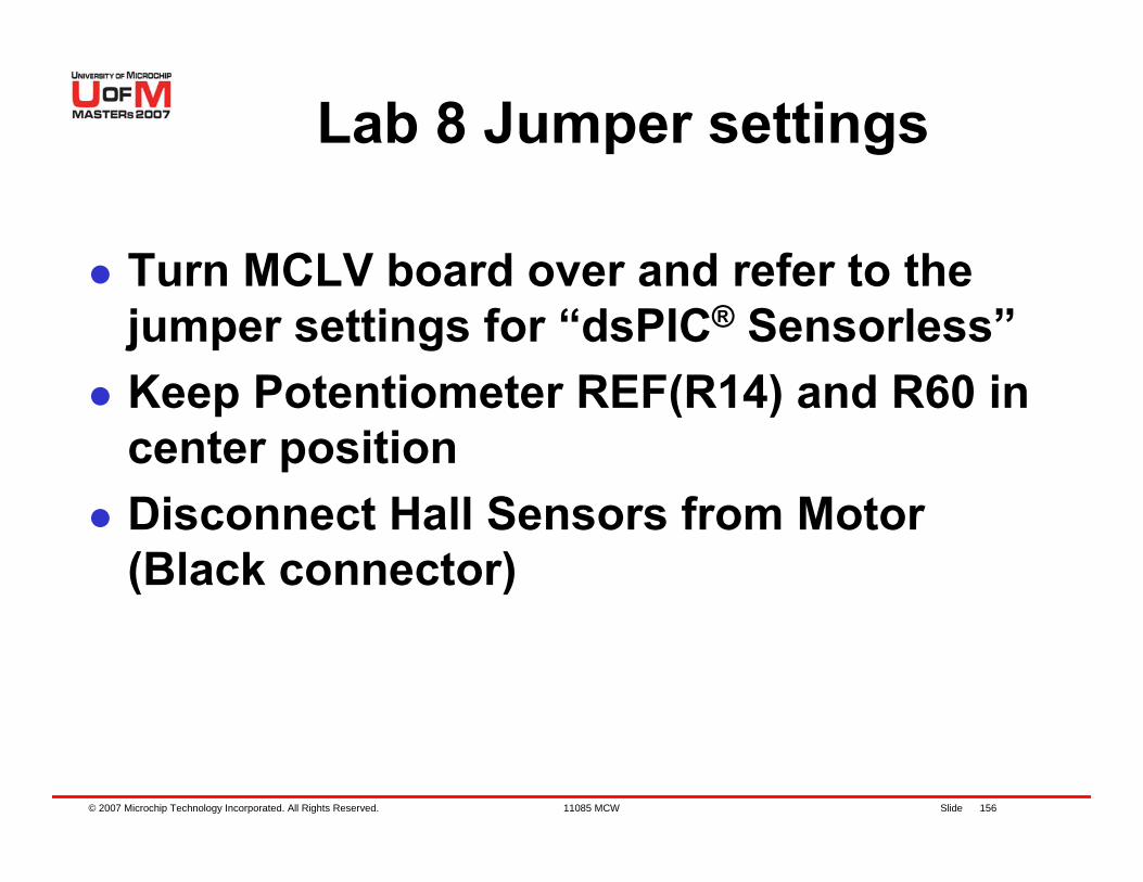
Lab 8 Jumper settings
Turn MCLV board over and refer to the jumper settings for “dsPIC® Sensorless”Keep Potentiometer REF(R14) and R60 in center positionDisconnect Hall Sensors from Motor (Black connector)
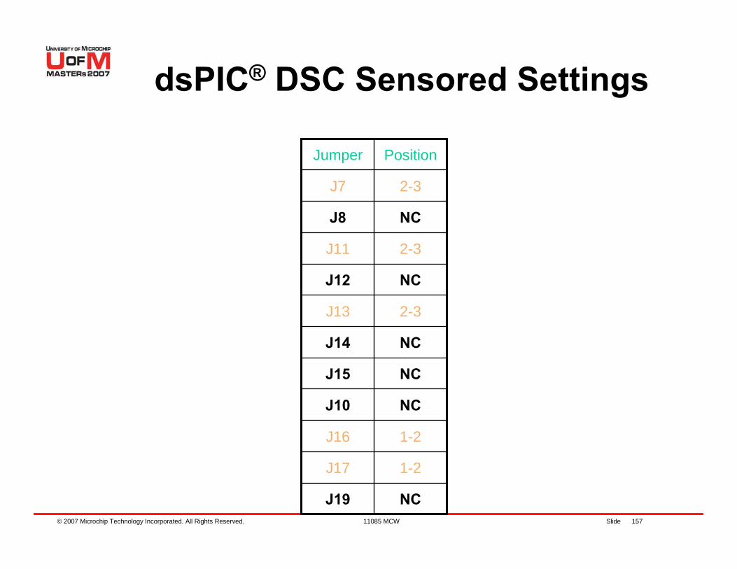
© 2007 Microchip Technology Incorporated. All Rights Reserved. 11085 MCW Slide 157
NCJ19
1-2J17
1-2J16
NCJ10
NCJ15
NCJ14
2-3J13
NCJ12
2-3J11
NCJ8
2-3J7
PositionJumper
dsPIC® DSC Sensored Settings
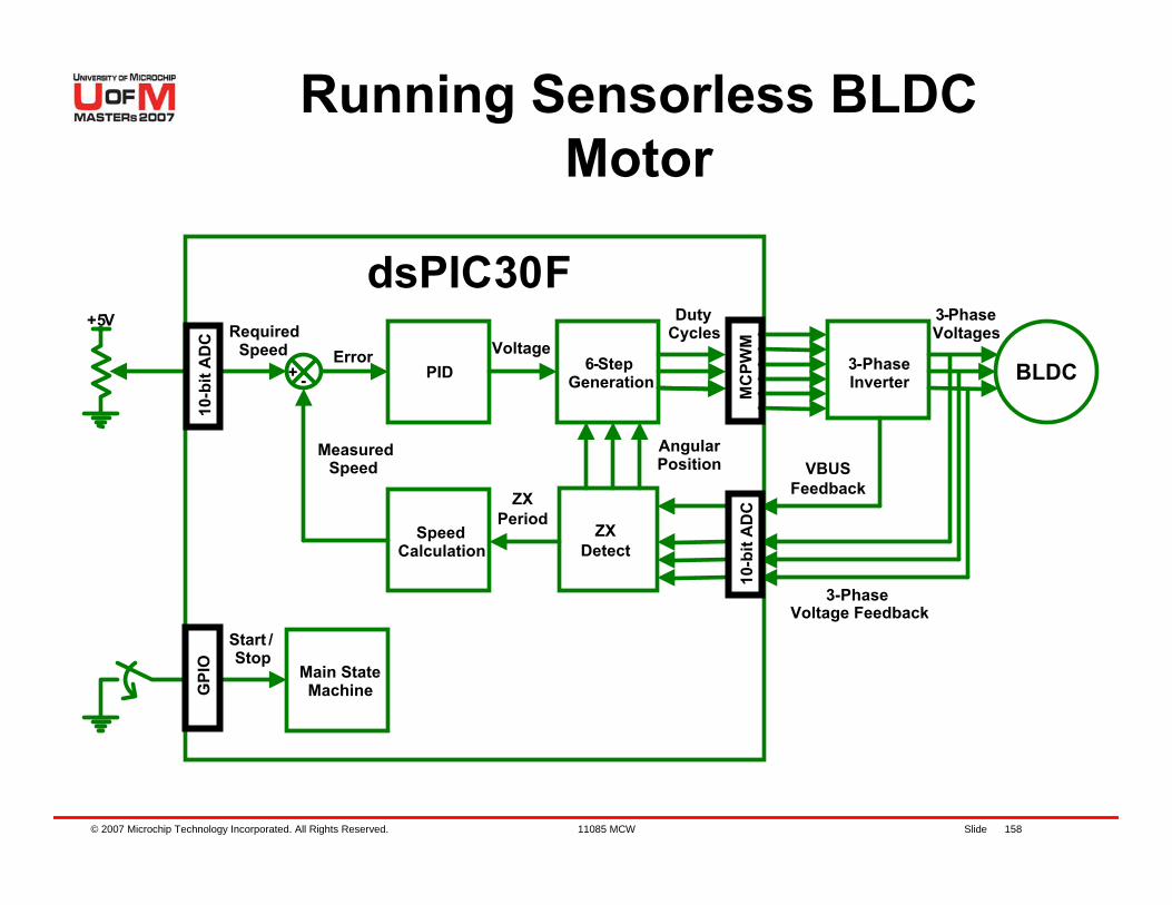
© 2007 Microchip Technology Incorporated. All Rights Reserved. 11085 MCW Slide 158
3-PhaseInverter BLDC6-Step
Generation
Main State Machine
Start /Stop
3-Phase Voltages
3-Phase Voltage Feedback
Angular Position
dsPIC30F+5V
RequiredSpeed
DutyCycles
+ - PIDError Voltage
SpeedCalculation
MeasuredSpeed
ZXPeriod
ZXDetect
VBUSFeedback
10-b
it A
DC
10-b
it A
DC
GPI
O
MC
PWM
Running Sensorless BLDC Motor
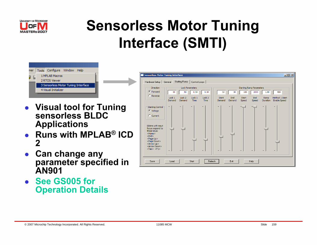
© 2007 Microchip Technology Incorporated. All Rights Reserved. 11085 MCW Slide 159
Visual tool for Tuning sensorless BLDC Applications Runs with MPLAB® ICD 2Can change any parameter specified in AN901See GS005 for Operation Details
Sensorless Motor Tuning Interface (SMTI)
© 2007 Microchip Technology Incorporated. All Rights Reserved. 11085 MCW Slide 160
Lab 8 – Running Sensorless BLDC Motor using dsPIC® DSC
Instructions for Lab 8:– Use workspace
“C:\RTC\301MCW\Lab8\Lab8.mcw”– Follow Lab 1 instructions to:
Compile codeProgram the dsPIC® DSCRun code
– Disconnect Black connector from Motor
Continued...
© 2007 Microchip Technology Incorporated. All Rights Reserved. 11085 MCW Slide 161
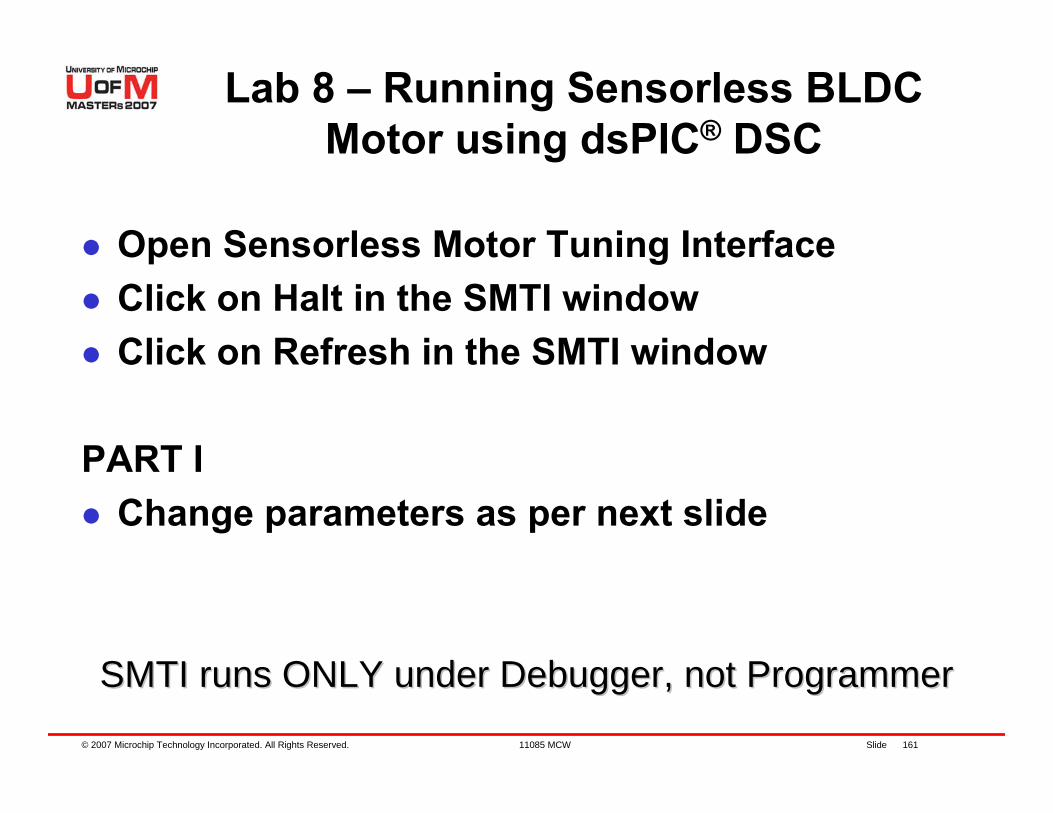
Open Sensorless Motor Tuning InterfaceClick on Halt in the SMTI windowClick on Refresh in the SMTI window
PART IChange parameters as per next slide
SMTI runs ONLY under Debugger, not ProgrammerSMTI runs ONLY under Debugger, not Programmer
Lab 8 – Running Sensorless BLDC Motor using dsPIC® DSC
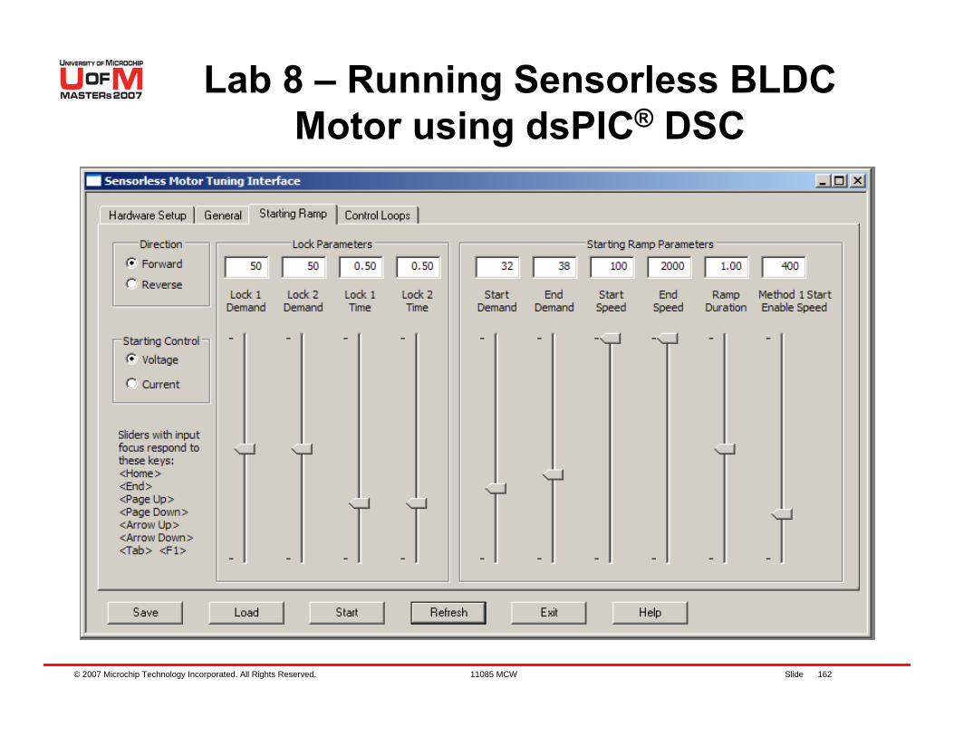
© 2007 Microchip Technology Incorporated. All Rights Reserved. 11085 MCW Slide 162
Lab 8 – Running Sensorless BLDC Motor using dsPIC® DSC
© 2007 Microchip Technology Incorporated. All Rights Reserved. 11085 MCW Slide 163
Lab 8 – Running Sensorless BLDC Motor using dsPIC® DSC
Click on Start in the SMTI windowPress S2 to start motorMotor appears to start but does not spinWHY?– Start demand is too low to keep the motor
running while ramping up– Hint. Increase the start/end speed ramp
demand when motor slips
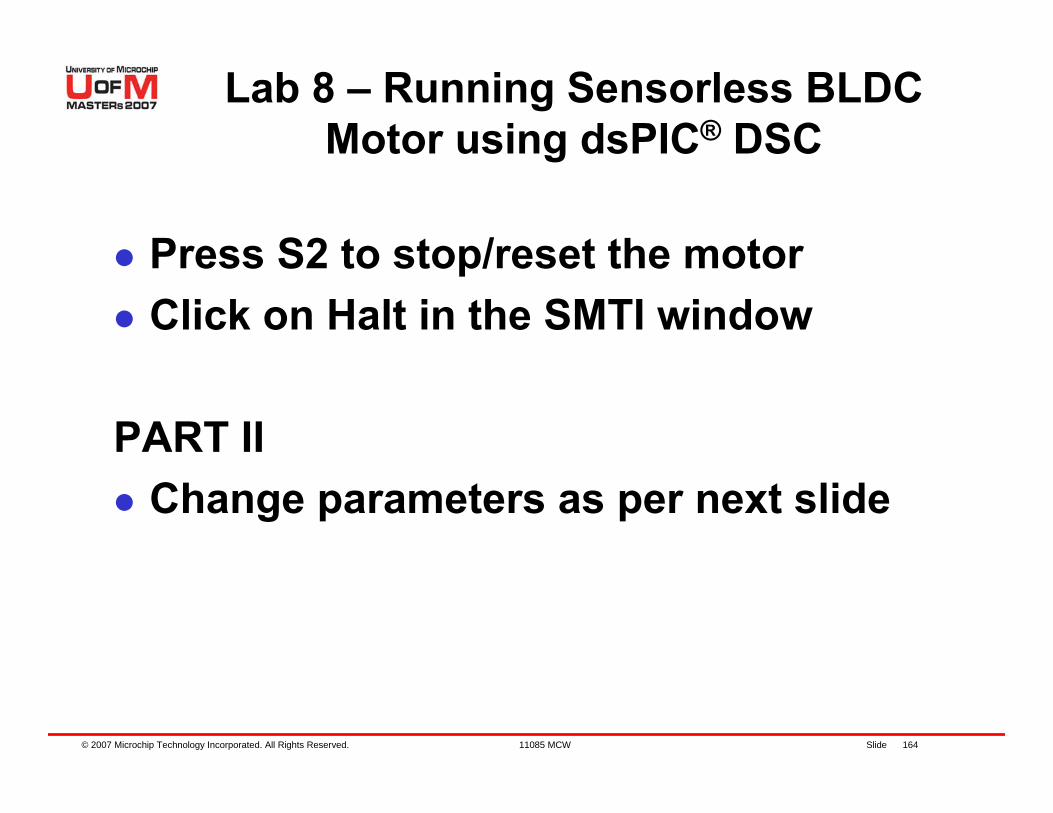
© 2007 Microchip Technology Incorporated. All Rights Reserved. 11085 MCW Slide 164
Lab 8 – Running Sensorless BLDC Motor using dsPIC® DSC
Press S2 to stop/reset the motorClick on Halt in the SMTI window
PART IIChange parameters as per next slide
© 2007 Microchip Technology Incorporated. All Rights Reserved. 11085 MCW Slide 165
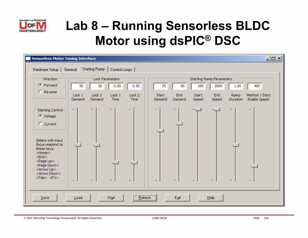
Lab 8 – Running Sensorless BLDC Motor using dsPIC® DSC
© 2007 Microchip Technology Incorporated. All Rights Reserved. 11085 MCW Slide 166
Lab 8 – Running Sensorless BLDC Motor using dsPIC® DSC
Click on Start in the SMTI windowPress S2 to start motorMotor appears to start but does not spinObserve the mechanics of the motorWhat is happening?
– The motor is vibrating in each sector while ramping up, because the demand was too high
– This generates a lot of start-up current and bad back EMF feedback
– Hint. Reduce the start/end demands when motor vibrates in every sector while ramping. If we reduce the demands more than we should, the motor will start slipping again
© 2007 Microchip Technology Incorporated. All Rights Reserved. 11085 MCW Slide 167
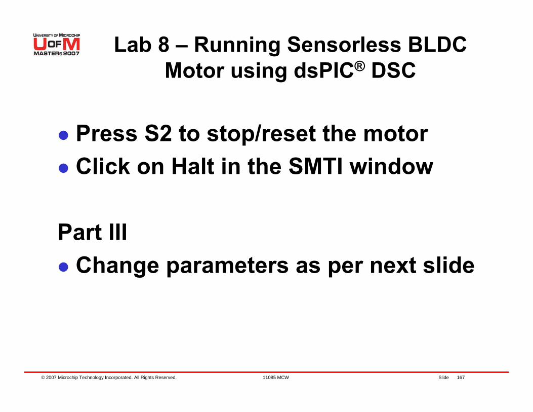
Lab 8 – Running Sensorless BLDC Motor using dsPIC® DSC
Press S2 to stop/reset the motorClick on Halt in the SMTI window
Part IIIChange parameters as per next slide
© 2007 Microchip Technology Incorporated. All Rights Reserved. 11085 MCW Slide 168
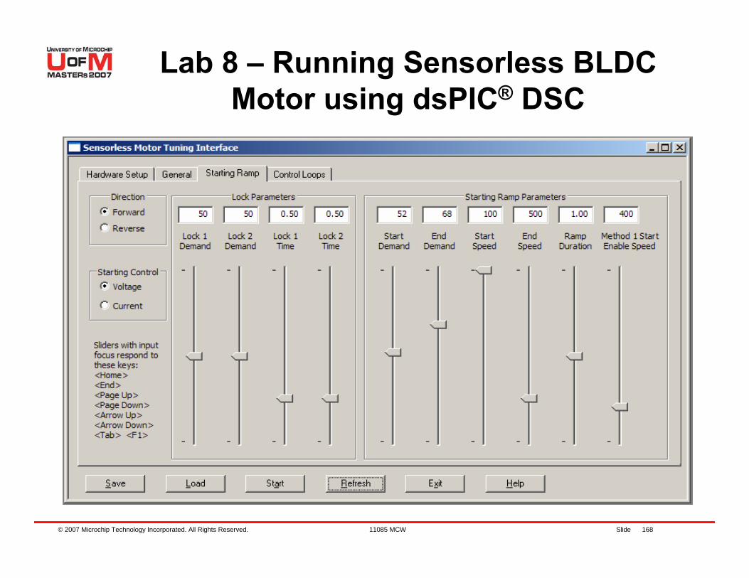
Lab 8 – Running Sensorless BLDC Motor using dsPIC® DSC
© 2007 Microchip Technology Incorporated. All Rights Reserved. 11085 MCW Slide 169
Lab 8 – Running Sensorless BLDC Motor using dsPIC® DSC
Click on Start in the SMTI windowPress S2 to start motorMotor appears to start but does not spinWhat is wrong?– The motor is ramping with good torque and does not
slip, but the end speed is too low. Back EMF zero crossings are still not detectable by the controller.
– Hint. When ramping up a motor, try to set a maximum speed of 50% of the motor rated speed, which is around 2000 RPM in this Motor
© 2007 Microchip Technology Incorporated. All Rights Reserved. 11085 MCW Slide 170
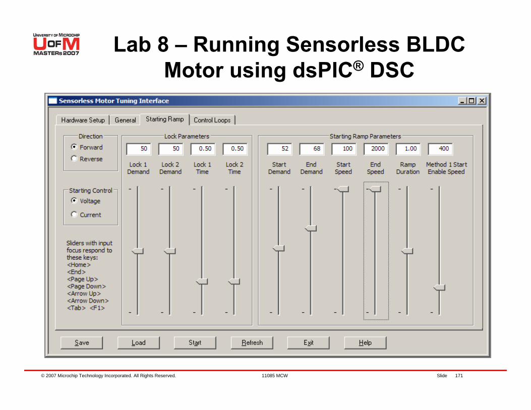
Lab 8 – Running Sensorless BLDC Motor using dsPIC® DSC
Press S2 to stop/reset the motorClick on Halt in the SMTI window
PART IVChange parameters as per next slide
© 2007 Microchip Technology Incorporated. All Rights Reserved. 11085 MCW Slide 171
Lab 8 – Running Sensorless BLDC Motor using dsPIC® DSC
© 2007 Microchip Technology Incorporated. All Rights Reserved. 11085 MCW Slide 172
Lab 8 – Running Sensorless BLDC Motor using dsPIC® DSC
Keep Pot in center positionClick on Start in the SMTI windowPress S2 to start motorDoes the motor spin?Press S2 to stop/reset the motor
Discuss why the motor spins Use AN992: Sensorless Control of BLDC motor
using dsPIC30F2010, for details
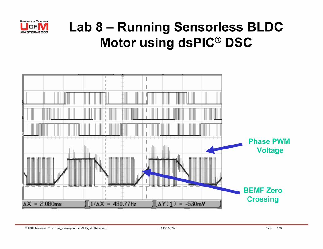
© 2007 Microchip Technology Incorporated. All Rights Reserved. 11085 MCW Slide 173
Phase PWM Voltage
BEMF ZeroCrossing
Lab 8 – Running Sensorless BLDC Motor using dsPIC® DSC
© 2007 Microchip Technology Incorporated. All Rights Reserved. 11085 MCW Slide 174
BLDC motor basicsBlindly spin a BLDC motorImprove efficiency by using Hall sensors Used dsPIC® DSC peripherals to spin a sensored BLDC motorControlling BLDC Speed with Digital PIDReducing audible noise of BLDC with Sinusoidal controlExtending speed range with Phase Advance controlTechniques for sensorless controlModified Parameters in AN901 to spin a sensorless BLDC motor
Summary
© 2007 Microchip Technology Incorporated. All Rights Reserved. 11085 MCW Slide 175
Reference Application Notes and Collateral
GS001: Getting Started with BLDC Motors and dsPIC30FGS002: Measuring Speed and Position with the QEI ModuleGS004: Driving an ACIM with the dsPIC® MWPWM ModuleGS005: Using the dsPIC30F Sensorless Motor Tuning Interface CE003: Driving a BLDC with Sinusoidal Voltages using dsPIC30FAN901: Sensorless Control of BLDC Motor using dsPIC30FAN907: Using the dsPIC30F for Vector Control of an ACIM AN957: Sensored Control of BLDC Motor using dsPIC30F2010 AN992: Sensorless Control of BLDC Motor using dsPIC30F2010
MICROCHIP REGIONAL TECHNOLOGY CENTER Cleveland Ohio 6133 Rockside Road, Suit e 101 Independence, OH 44131
STU CHANDLERSr. Technical Training Engineer
216-447-0464 st [email protected]
NOVEMBER 3, 2006
What’s new this week at the RTC ?
• We are offering an open house this month for the first time. This will be a monthly event scheduled for the
second Monday of each month. Running from 11:00AM to 2:00PM we will have pizza as well as a review of what new products Microchip has released. Come on in and get to meet your FAE and Field Sales as well as the management team that makes it all happen. You can register through the website, or just come on in at your convenience.
• Schedules for Cleveland and Detroit have are updated through the end of November and available to register via
the website -> www.microchip.com/RTC • We are continuing to offer evening classes; the next one is Thanksgiving week in Cleveland when we offer
101_TLS Getting Started on Tuesday evening. This class runs from 5:30PM to 9:00PM and will get you out in plenty of time to get home for Thanksgiving.
• The week of October 8th all Technical Training Engineers around the world met in Arizona to be review latest
classes to be released. We met with the authors of the classes in cooperative discussions regarding how to make the classes as effective as possible. We also had a preview of several new classes that will be rolled out in the coming weeks. Watch the January schedule for several exciting new offerings.
• The Embedded C class is in development and on-track to be scheduled in February. This class has been the
most requested of any that we have proposed and is the highest priority in the curriculum pipeline. It will be based on MPLAB-C30 and is currently envisioned to be an intensive three day class.
• As a reminder there are seven new classes including a full PIC24/dsPIC curriculum as well as an analog track.
Watch the December schedule for classes on op amps and battery chargers • This November sees an old favorite - 301_MCW: dsPIC30F Motor Control Workshop in a Box class. This
has been a perennial favorite and we are please to place it on the RTC schedule for the first time this year.
ABOUT YOUR INSTRUCTOR Wit h more t han 30 year experience in all aspect s of t he elect ronics indust ry, St u Chandler not only explains t he what and how but also t he why behind Microchip’s embedded t echnologies.

© 2007 Microchip Technology Incorporated. All Rights Reserved. 11085 MCW Slide 176
Thank You for Attending!
© 2007 Microchip Technology Incorporated. All Rights Reserved. 11085 MCW Slide 177
TrademarksThe Microchip name and logo, the Microchip logo, Accuron, dsPIC, KeeLoq, KeeLoq logo, microID, MPLAB, PIC, PICmicro, PICSTART, PRO MATE, rfPICand SmartShunt are registered trademarks of Microchip Technology Incorporated in the U.S.A. and other countries.AmpLab, FilterLab, Linear Active Thermistor, Migratable Memory, MXDEV, MXLAB, SEEVAL, SmartSensor and The Embedded Control Solutions Company are registered trademarks of Microchip Technology Incorporated in the U.S.A.Analog-for-the-Digital Age, Application Maestro, CodeGuard, dsPICDEM, dsPICDEM.net, dsPICworks, ECAN, ECONOMONITOR, FanSense, FlexROM, fuzzyLAB, In-Circuit Serial Programming, ICSP, ICEPIC, Mindi, MiWi, MPASM, MPLAB Certified logo, MPLIB, MPLINK, PICkit, PICDEM, PICDEM.net, PICLAB, PICtail, PowerCal, PowerInfo, PowerMate, PowerTool, REAL ICE, rfLAB, Select Mode, Smart Serial, SmartTel, Total Endurance, UNI/O, WiperLock and ZENA are trademarks of Microchip TechnologyIncorporated in the U.S.A. and other countries.SQTP is a service mark of Microchip Technology Incorporated in the U.S.A.All other trademarks mentioned herein are property of their respective companies.