Embed Size (px)
Citation preview
U.S. EPR FINAL SAFETY ANALYSIS REPORT
1.0 Introduction and General Description of the Plant
1.1 Introduction
AREVA NP submits for NRC review and approval under the provisions of 10 CFR 52, a Final Safety Analysis Report (FSAR) for an evolutionary pressurized water reactor, the U.S. EPR™ (herein after referred to as the U.S. EPR). AREVA NP requests NRC issuance of a Safety Evaluation Report (SER) and standard design certification for the U.S. EPR in accordance with 10 CFR 52, Subpart B. For the purpose of this document, only a single standard unit is considered. A combined license (COL) applicant that references the U.S. EPR design certification and proposes a multi-unit license application will provide the changes and additional information needed to license a multi-unit plant.
1.1.1 Plant Location
The U.S. EPR is to be located on a site which meets the parameters described in Chapter 2, “Site Characteristics.” A COL applicant that references the U.S. EPR design certification will identify the specific plant site location.
1.1.2 Containment Type
The Containment Building for the U.S. EPR is part of an integrated structure called the Reactor Building. The Reactor Building consists of a cylindrical reinforced concrete outer Shield Building; a cylindrical, post-tensioned concrete inner Containment Building with a steel liner, and an annular space between the two buildings. The Shield Building is capable of protecting the Containment Building from external hazards.
1.1.3 Reactor Type
The U.S. EPR nuclear steam supply system is an AREVA NP-designed evolutionary pressurized water reactor.
1.1.4 Power Output
The U.S. EPR is designed for a rated core thermal power level of 4590 MWt with a bounding secondary heat balance uncertainty of ± 22 MWt. The nuclear steam supply system (NSSS) thermal power rating is about 4614 MWt. The plant is designed to operate at a net electrical power output of approximately 1600 MWe.
1.1.5 Schedule
A COL applicant that references the U.S. EPR design certification will provide the estimated schedules for completion of construction and commercial operation.
Tier 2 Revision 2 Page 1.1-1
U.S. EPR FINAL SAFETY ANALYSIS REPORT
1.1.6 Format and Content
1.1.6.1 Regulatory Guide 1.206
To the extent practical, this document is written in accordance with the format and content of RG 1.206, Rev. 0, “Combined License Applications for Nuclear Power Plants (LWR Edition),” March 2007. While the purpose of this RG is to provide guidance regarding the information to be submitted in a combined license application, AREVA NP has structured the FSAR for the U.S. EPR to be consistent to the extent practical with the format and content that would be expected for a COL applicant. Because the Standard Review Plan (NUREG-0800) was revised to be consistent with the guidance provided in RG 1.206, this should facilitate the NRC review of the FSAR and a COL application that references the U.S. EPR design certification.
1.1.6.2 Standard Review Plan
NUREG-0800 is used as guidance in preparing the content for individual sections of this document. Conformance with the Standard Review Plan is addressed in Section 1.9.
1.1.6.3 Text, Tables and Figures
Tables and figures are identified by the section or subsection in which they appear and are numbered sequentially. For example, Table 1.1-1 and Figure 1.1-1 would be the first table and figure appearing in Section 1.1. Figures consist of diagrams, plots, pictures, graphs or other illustrations. Tables and figures are located at the end of the applicable section or subsection immediately following the text.
1.1.6.4 Numbering of Pages
Pages are numbered sequentially within each section or subsection.
1.1.6.5 Proprietary Information
This document contains no proprietary information. As noted in Section 1.6, the FSAR references topical reports that contain proprietary information. In these cases, in Table 1.6-1, the non-proprietary version of the topical report is also identified.
1.1.6.6 Acronyms
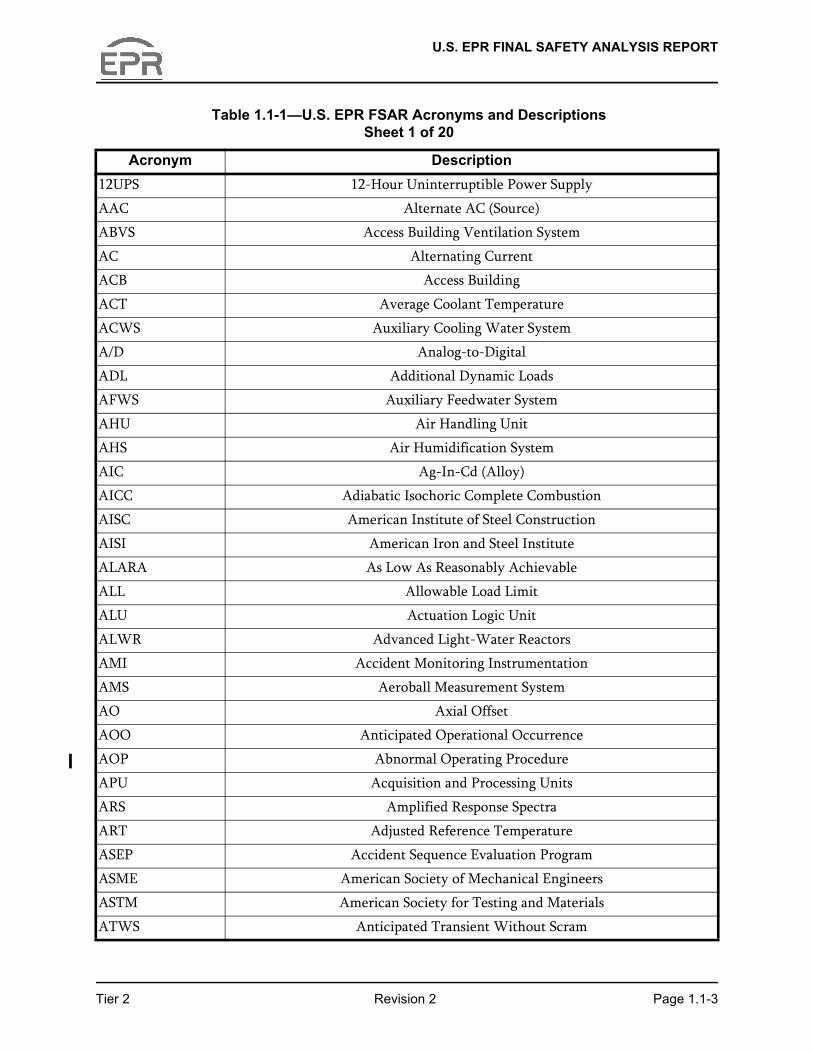
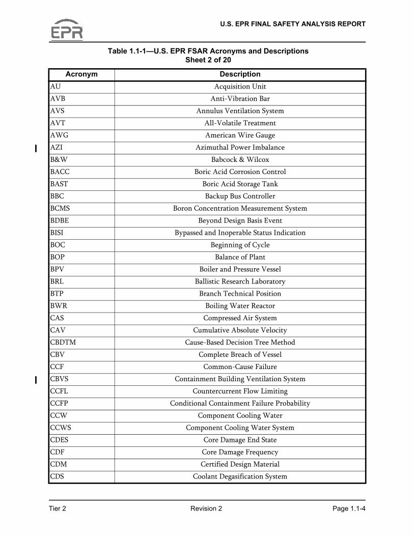
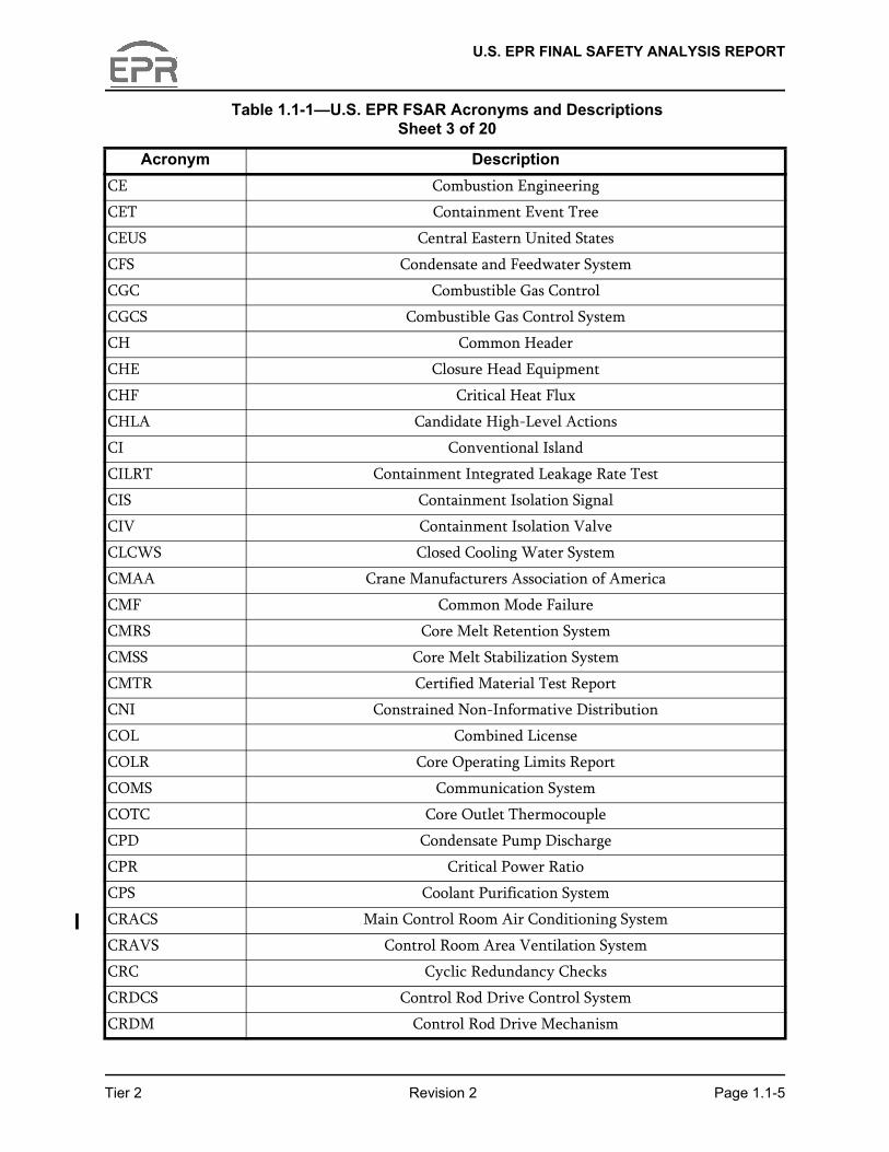
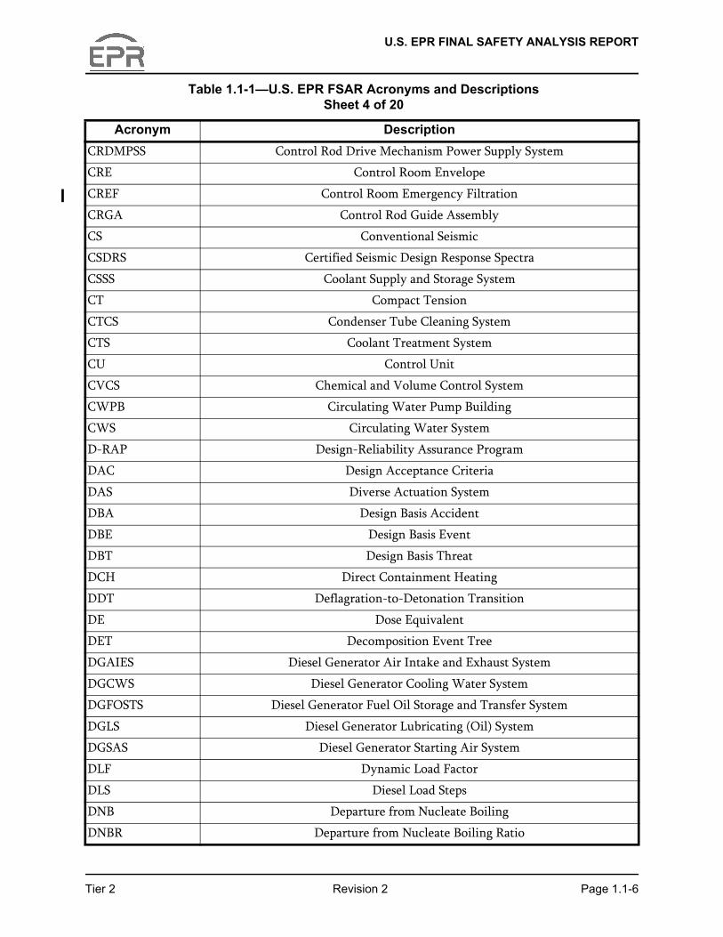
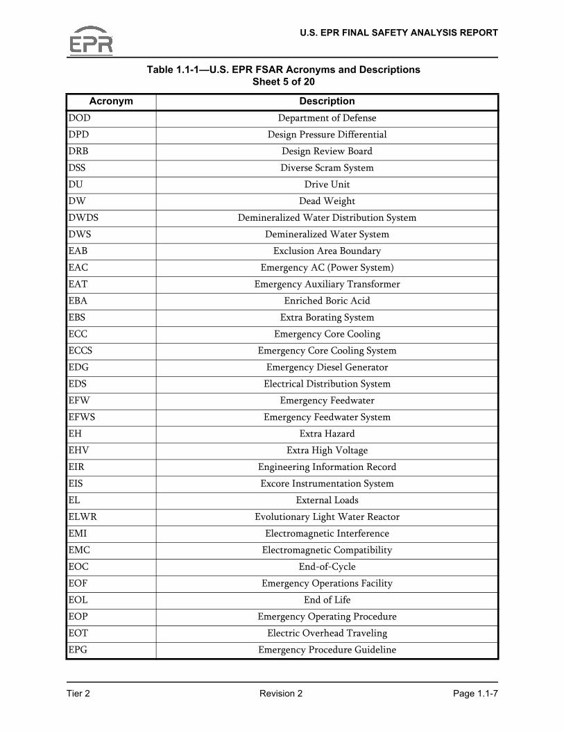
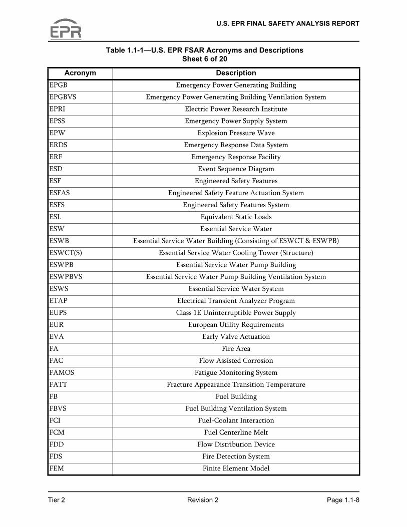
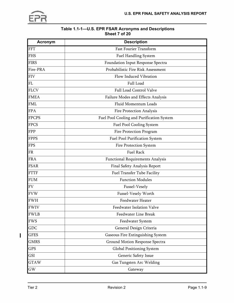
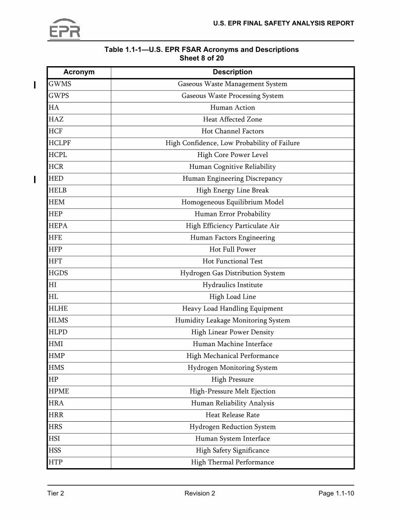
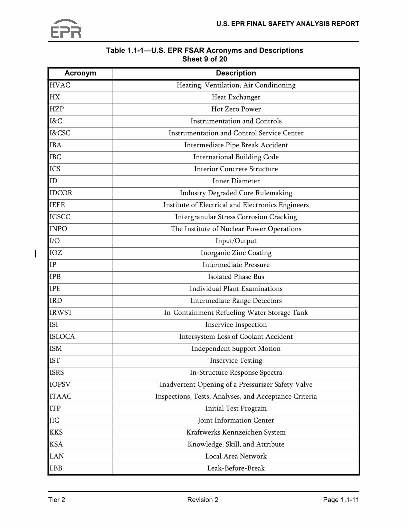
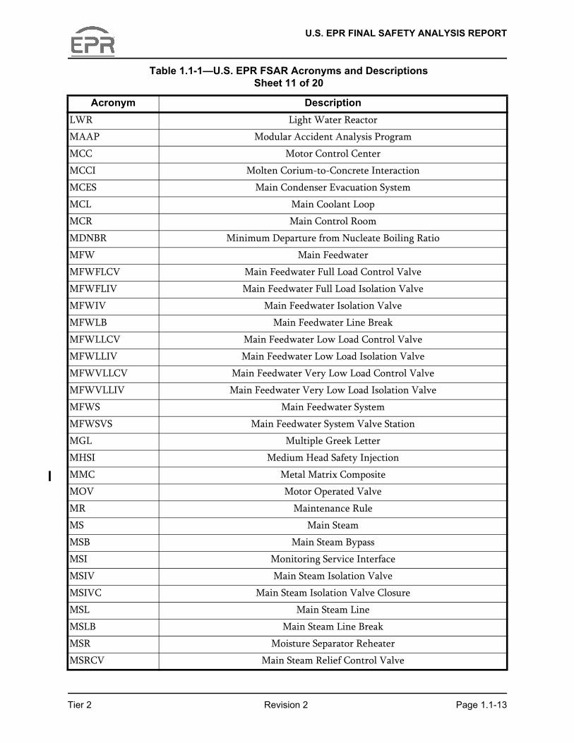
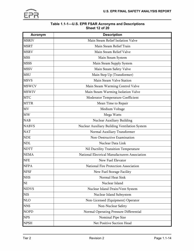
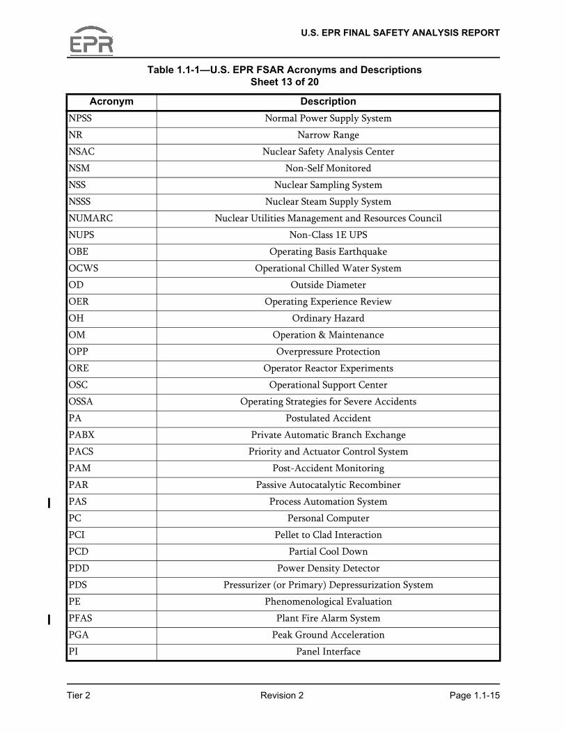
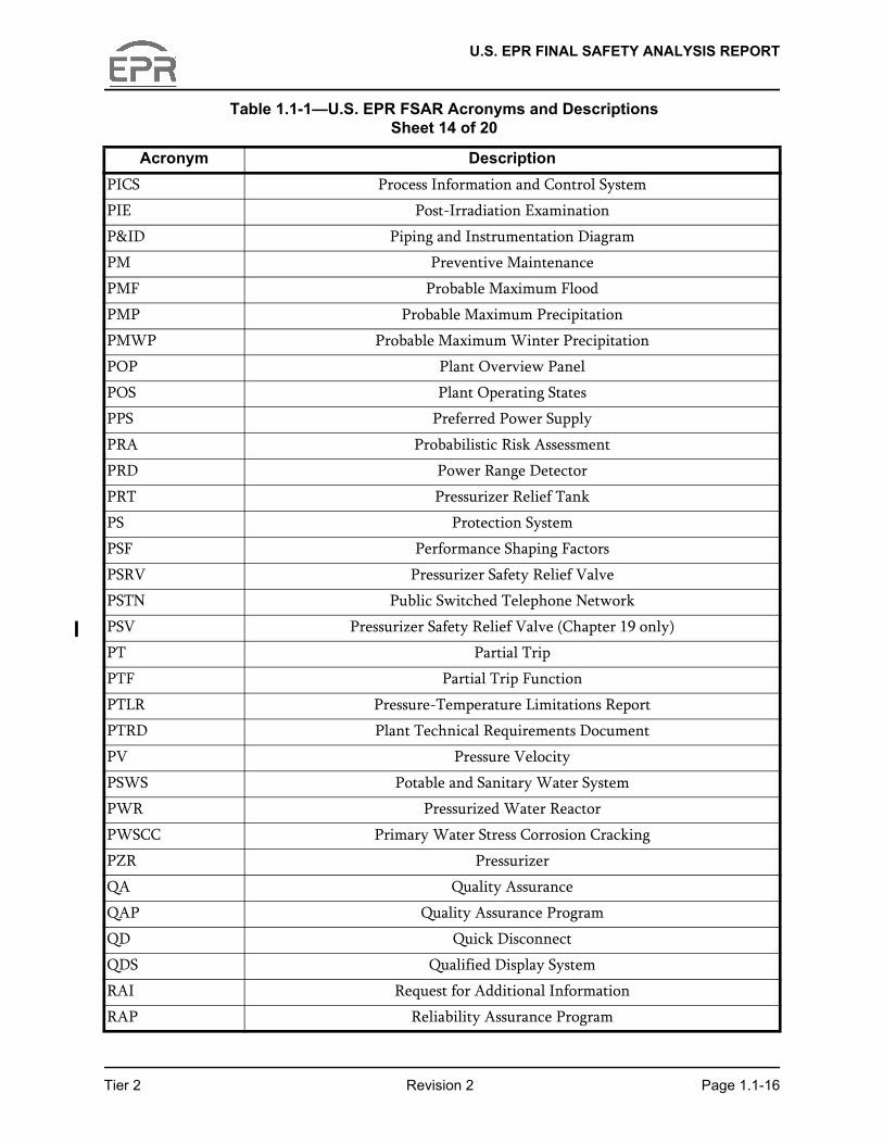
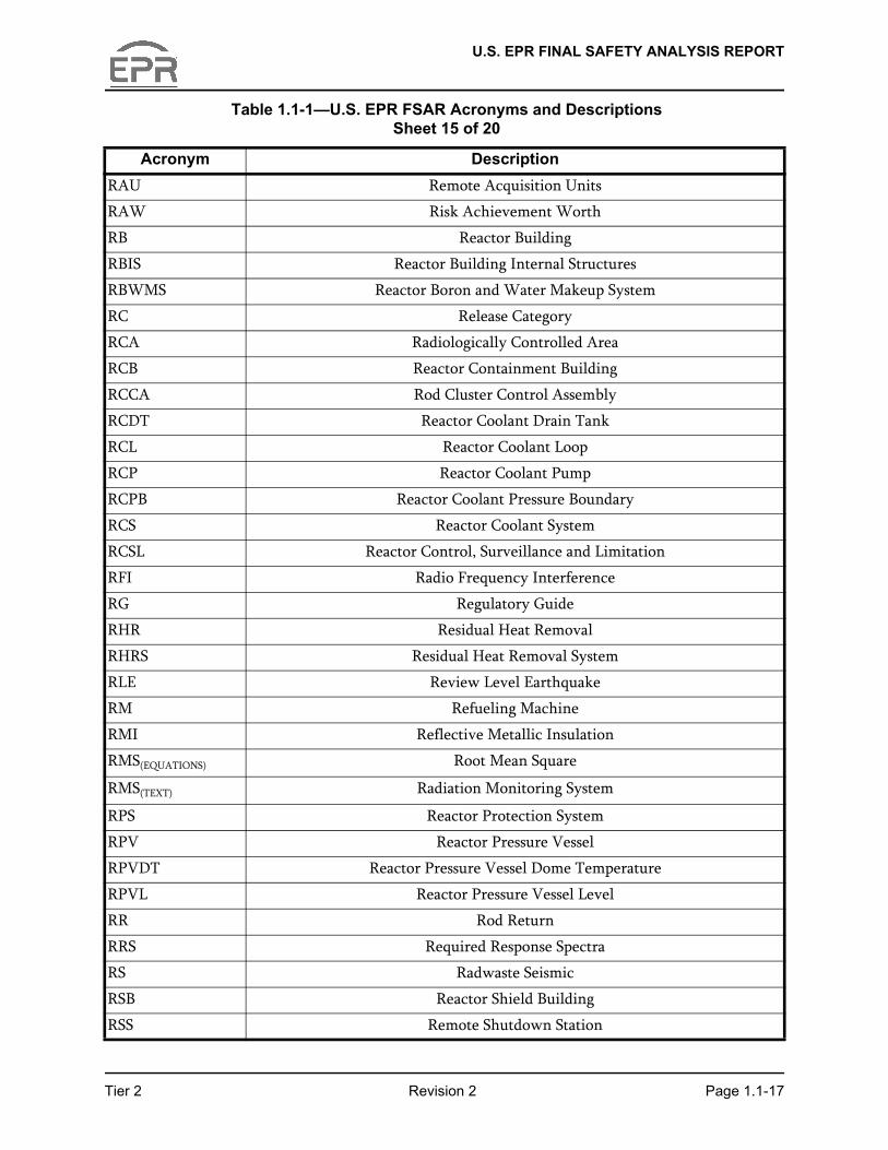
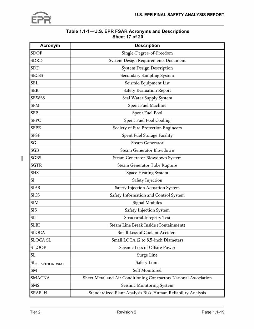
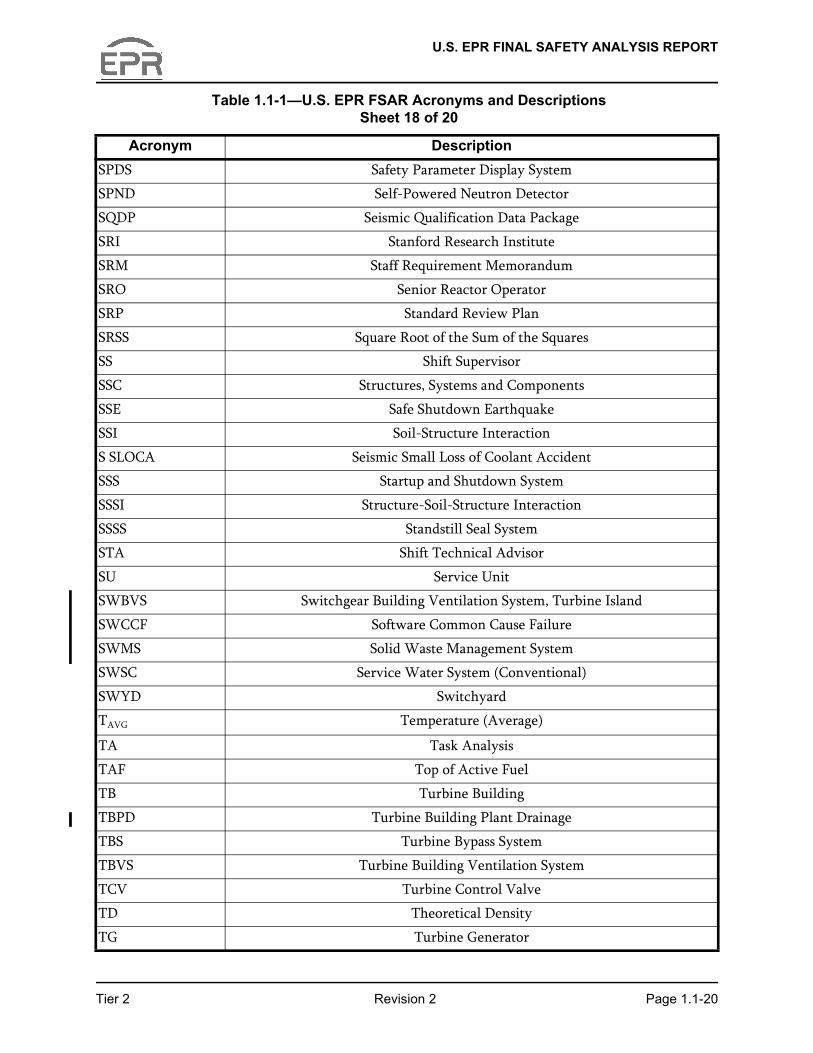
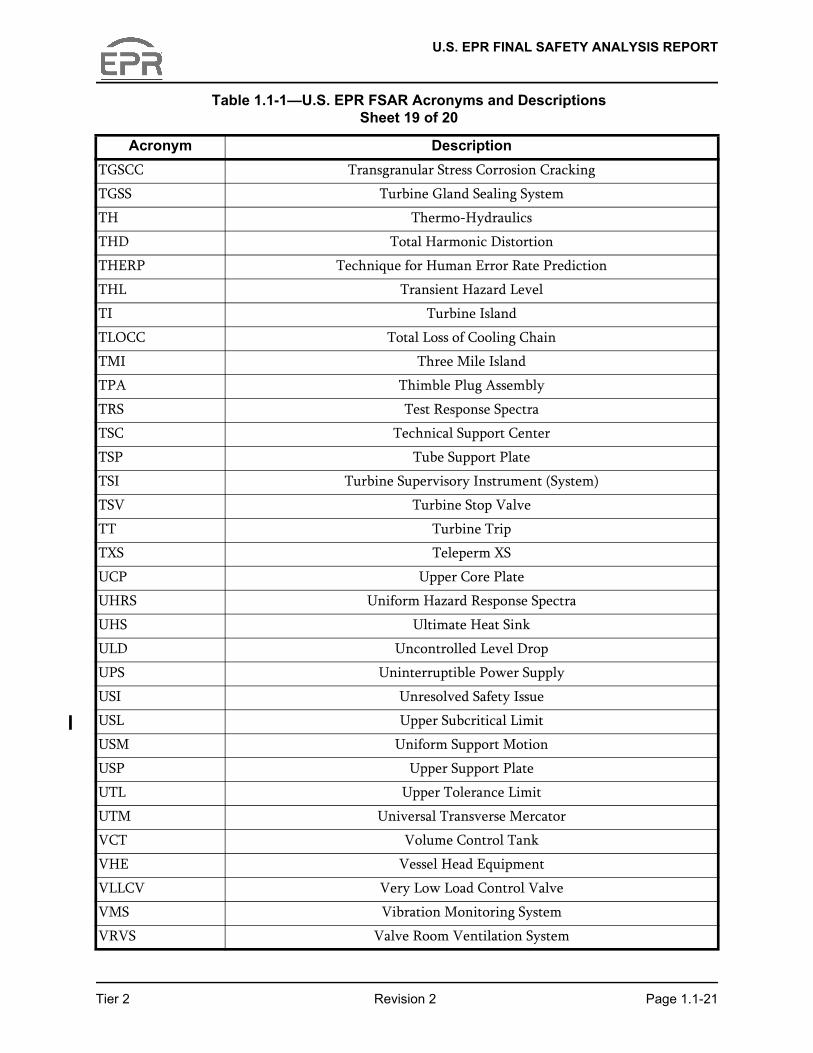
The list of acronyms used in this document is provided in Table 1.1-1—U.S. EPR FSAR Acronyms and Descriptions.
1.1.6.7 COL Information Items
A list of COL information items to be addressed by an applicant that references the U.S. EPR design certification is provided in Section 1.8.
Tier 2 Revision 2 Page 1.1-2
U.S. EPR FINAL SAFETY ANALYSIS REPORT
Table 1.1-1—U.S. EPR FSAR Acronyms and Descriptions Sheet 1 of 20
Acronym Description12UPS 12-Hour Uninterruptible Power Supply
AAC Alternate AC (Source)
ABVS Access Building Ventilation System
AC Alternating Current
ACB Access Building
ACT Average Coolant Temperature
ACWS Auxiliary Cooling Water System
A/D Analog-to-Digital
ADL Additional Dynamic Loads
AFWS Auxiliary Feedwater System
AHU Air Handling Unit
AHS Air Humidification System
AIC Ag-In-Cd (Alloy)
AICC Adiabatic Isochoric Complete Combustion
AISC American Institute of Steel Construction
AISI American Iron and Steel Institute
ALARA As Low As Reasonably Achievable
ALL Allowable Load Limit
ALU Actuation Logic Unit
ALWR Advanced Light-Water Reactors
AMI Accident Monitoring Instrumentation
AMS Aeroball Measurement System
AO Axial Offset
AOO Anticipated Operational Occurrence
AOP Abnormal Operating Procedure
APU Acquisition and Processing Units
ARS Amplified Response Spectra
ART Adjusted Reference Temperature
ASEP Accident Sequence Evaluation Program
ASME American Society of Mechanical Engineers
ASTM American Society for Testing and Materials
ATWS Anticipated Transient Without Scram
Tier 2 Revision 2 Page 1.1-3
U.S. EPR FINAL SAFETY ANALYSIS REPORT
AU Acquisition Unit
AVB Anti-Vibration Bar
AVS Annulus Ventilation System
AVT All-Volatile Treatment
AWG American Wire Gauge
AZI Azimuthal Power Imbalance
B&W Babcock & Wilcox
BACC Boric Acid Corrosion Control
BAST Boric Acid Storage Tank
BBC Backup Bus Controller
BCMS Boron Concentration Measurement System
BDBE Beyond Design Basis Event
BISI Bypassed and Inoperable Status Indication
BOC Beginning of Cycle
BOP Balance of Plant
BPV Boiler and Pressure Vessel
BRL Ballistic Research Laboratory
BTP Branch Technical Position
BWR Boiling Water Reactor
CAS Compressed Air System
CAV Cumulative Absolute Velocity
CBDTM Cause-Based Decision Tree Method
CBV Complete Breach of Vessel
CCF Common-Cause Failure
CBVS Containment Building Ventilation System
CCFL Countercurrent Flow Limiting
CCFP Conditional Containment Failure Probability
CCW Component Cooling Water
CCWS Component Cooling Water System
CDES Core Damage End State
CDF Core Damage Frequency
CDM Certified Design Material
CDS Coolant Degasification System
Table 1.1-1—U.S. EPR FSAR Acronyms and Descriptions Sheet 2 of 20
Acronym Description
Tier 2 Revision 2 Page 1.1-4
U.S. EPR FINAL SAFETY ANALYSIS REPORT
CE Combustion Engineering
CET Containment Event Tree
CEUS Central Eastern United States
CFS Condensate and Feedwater System
CGC Combustible Gas Control
CGCS Combustible Gas Control System
CH Common Header
CHE Closure Head Equipment
CHF Critical Heat Flux
CHLA Candidate High-Level Actions
CI Conventional Island
CILRT Containment Integrated Leakage Rate Test
CIS Containment Isolation Signal
CIV Containment Isolation Valve
CLCWS Closed Cooling Water System
CMAA Crane Manufacturers Association of America
CMF Common Mode Failure
CMRS Core Melt Retention System
CMSS Core Melt Stabilization System
CMTR Certified Material Test Report
CNI Constrained Non-Informative Distribution
COL Combined License
COLR Core Operating Limits Report
COMS Communication System
COTC Core Outlet Thermocouple
CPD Condensate Pump Discharge
CPR Critical Power Ratio
CPS Coolant Purification System
CRACS Main Control Room Air Conditioning System
CRAVS Control Room Area Ventilation System
CRC Cyclic Redundancy Checks
CRDCS Control Rod Drive Control System
CRDM Control Rod Drive Mechanism
Table 1.1-1—U.S. EPR FSAR Acronyms and Descriptions Sheet 3 of 20
Acronym Description
Tier 2 Revision 2 Page 1.1-5
U.S. EPR FINAL SAFETY ANALYSIS REPORT
CRDMPSS Control Rod Drive Mechanism Power Supply System
CRE Control Room Envelope
CREF Control Room Emergency Filtration
CRGA Control Rod Guide Assembly
CS Conventional Seismic
CSDRS Certified Seismic Design Response Spectra
CSSS Coolant Supply and Storage System
CT Compact Tension
CTCS Condenser Tube Cleaning System
CTS Coolant Treatment System
CU Control Unit
CVCS Chemical and Volume Control System
CWPB Circulating Water Pump Building
CWS Circulating Water System
D-RAP Design-Reliability Assurance Program
DAC Design Acceptance Criteria
DAS Diverse Actuation System
DBA Design Basis Accident
DBE Design Basis Event
DBT Design Basis Threat
DCH Direct Containment Heating
DDT Deflagration-to-Detonation Transition
DE Dose Equivalent
DET Decomposition Event Tree
DGAIES Diesel Generator Air Intake and Exhaust System
DGCWS Diesel Generator Cooling Water System
DGFOSTS Diesel Generator Fuel Oil Storage and Transfer System
DGLS Diesel Generator Lubricating (Oil) System
DGSAS Diesel Generator Starting Air System
DLF Dynamic Load Factor
DLS Diesel Load Steps
DNB Departure from Nucleate Boiling
DNBR Departure from Nucleate Boiling Ratio
Table 1.1-1—U.S. EPR FSAR Acronyms and Descriptions Sheet 4 of 20
Acronym Description
Tier 2 Revision 2 Page 1.1-6
U.S. EPR FINAL SAFETY ANALYSIS REPORT
DOD Department of Defense
DPD Design Pressure Differential
DRB Design Review Board
DSS Diverse Scram System
DU Drive Unit
DW Dead Weight
DWDS Demineralized Water Distribution System
DWS Demineralized Water System
EAB Exclusion Area Boundary
EAC Emergency AC (Power System)
EAT Emergency Auxiliary Transformer
EBA Enriched Boric Acid
EBS Extra Borating System
ECC Emergency Core Cooling
ECCS Emergency Core Cooling System
EDG Emergency Diesel Generator
EDS Electrical Distribution System
EFW Emergency Feedwater
EFWS Emergency Feedwater System
EH Extra Hazard
EHV Extra High Voltage
EIR Engineering Information Record
EIS Excore Instrumentation System
EL External Loads
ELWR Evolutionary Light Water Reactor
EMI Electromagnetic Interference
EMC Electromagnetic Compatibility
EOC End-of-Cycle
EOF Emergency Operations Facility
EOL End of Life
EOP Emergency Operating Procedure
EOT Electric Overhead Traveling
EPG Emergency Procedure Guideline
Table 1.1-1—U.S. EPR FSAR Acronyms and Descriptions Sheet 5 of 20
Acronym Description
Tier 2 Revision 2 Page 1.1-7
U.S. EPR FINAL SAFETY ANALYSIS REPORT
EPGB Emergency Power Generating Building
EPGBVS Emergency Power Generating Building Ventilation System
EPRI Electric Power Research Institute
EPSS Emergency Power Supply System
EPW Explosion Pressure Wave
ERDS Emergency Response Data System
ERF Emergency Response Facility
ESD Event Sequence Diagram
ESF Engineered Safety Features
ESFAS Engineered Safety Feature Actuation System
ESFS Engineered Safety Features System
ESL Equivalent Static Loads
ESW Essential Service Water
ESWB Essential Service Water Building (Consisting of ESWCT & ESWPB)
ESWCT(S) Essential Service Water Cooling Tower (Structure)
ESWPB Essential Service Water Pump Building
ESWPBVS Essential Service Water Pump Building Ventilation System
ESWS Essential Service Water System
ETAP Electrical Transient Analyzer Program
EUPS Class 1E Uninterruptible Power Supply
EUR European Utility Requirements
EVA Early Valve Actuation
FA Fire Area
FAC Flow Assisted Corrosion
FAMOS Fatigue Monitoring System
FATT Fracture Appearance Transition Temperature
FB Fuel Building
FBVS Fuel Building Ventilation System
FCI Fuel-Coolant Interaction
FCM Fuel Centerline Melt
FDD Flow Distribution Device
FDS Fire Detection System
FEM Finite Element Model
Table 1.1-1—U.S. EPR FSAR Acronyms and Descriptions Sheet 6 of 20
Acronym Description
Tier 2 Revision 2 Page 1.1-8
U.S. EPR FINAL SAFETY ANALYSIS REPORT
FFT Fast Fourier Transform
FHS Fuel Handling System
FIRS Foundation Input Response Spectra
Fire-PRA Probabilistic Fire Risk Assessment
FIV Flow Induced Vibration
FL Full Load
FLCV Full Load Control Valve
FMEA Failure Modes and Effects Analysis
FML Fluid Momentum Loads
FPA Fire Protection Analysis
FPCPS Fuel Pool Cooling and Purification System
FPCS Fuel Pool Cooling System
FPP Fire Protection Program
FPPS Fuel Pool Purification System
FPS Fire Protection System
FR Fuel Rack
FRA Functional Requirements Analysis
FSAR Final Safety Analysis Report
FTTF Fuel Transfer Tube Facility
FUM Function Modules
FV Fussel-Vesely
FVW Fussel-Vesely Worth
FWH Feedwater Heater
FWIV Feedwater Isolation Valve
FWLB Feedwater Line Break
FWS Feedwater System
GDC General Design Criteria
GFES Gaseous Fire Extinguishing System
GMRS Ground Motion Response Spectra
GPS Global Positioning System
GSI Generic Safety Issue
GTAW Gas Tungsten Arc Welding
GW Gateway
Table 1.1-1—U.S. EPR FSAR Acronyms and Descriptions Sheet 7 of 20
Acronym Description
Tier 2 Revision 2 Page 1.1-9
U.S. EPR FINAL SAFETY ANALYSIS REPORT
GWMS Gaseous Waste Management System
GWPS Gaseous Waste Processing System
HA Human Action
HAZ Heat Affected Zone
HCF Hot Channel Factors
HCLPF High Confidence, Low Probability of Failure
HCPL High Core Power Level
HCR Human Cognitive Reliability
HED Human Engineering Discrepancy
HELB High Energy Line Break
HEM Homogeneous Equilibrium Model
HEP Human Error Probability
HEPA High Efficiency Particulate Air
HFE Human Factors Engineering
HFP Hot Full Power
HFT Hot Functional Test
HGDS Hydrogen Gas Distribution System
HI Hydraulics Institute
HL High Load Line
HLHE Heavy Load Handling Equipment
HLMS Humidity Leakage Monitoring System
HLPD High Linear Power Density
HMI Human Machine Interface
HMP High Mechanical Performance
HMS Hydrogen Monitoring System
HP High Pressure
HPME High-Pressure Melt Ejection
HRA Human Reliability Analysis
HRR Heat Release Rate
HRS Hydrogen Reduction System
HSI Human System Interface
HSS High Safety Significance
HTP High Thermal Performance
Table 1.1-1—U.S. EPR FSAR Acronyms and Descriptions Sheet 8 of 20
Acronym Description
Tier 2 Revision 2 Page 1.1-10
U.S. EPR FINAL SAFETY ANALYSIS REPORT
HVAC Heating, Ventilation, Air Conditioning
HX Heat Exchanger
HZP Hot Zero Power
I&C Instrumentation and Controls
I&CSC Instrumentation and Control Service Center
IBA Intermediate Pipe Break Accident
IBC International Building Code
ICS Interior Concrete Structure
ID Inner Diameter
IDCOR Industry Degraded Core Rulemaking
IEEE Institute of Electrical and Electronics Engineers
IGSCC Intergranular Stress Corrosion Cracking
INPO The Institute of Nuclear Power Operations
I/O Input/Output
IOZ Inorganic Zinc Coating
IP Intermediate Pressure
IPB Isolated Phase Bus
IPE Individual Plant Examinations
IRD Intermediate Range Detectors
IRWST In-Containment Refueling Water Storage Tank
ISI Inservice Inspection
ISLOCA Intersystem Loss of Coolant Accident
ISM Independent Support Motion
IST Inservice Testing
ISRS In-Structure Response Spectra
IOPSV Inadvertent Opening of a Pressurizer Safety Valve
ITAAC Inspections, Tests, Analyses, and Acceptance Criteria
ITP Initial Test Program
JIC Joint Information Center
KKS Kraftwerks Kennzeichen System
KSA Knowledge, Skill, and Attribute
LAN Local Area Network
LBB Leak-Before-Break
Table 1.1-1—U.S. EPR FSAR Acronyms and Descriptions Sheet 9 of 20
Acronym Description
Tier 2 Revision 2 Page 1.1-11

U.S. EPR FINAL SAFETY ANALYSIS REPORT
LBD Licensing Basis Documentation
LBLOCA Large Break Loss of Coolant Accident
LBOP TR Loss of Balance of Plant
LC Load Center
LCO Limiting Conditions for Operation
LCS Local Control Stations
LHSI Low Head Safety Injection
LL Low Load Line
LLCV Low Load Control Valve
LLRT Local Leakage Rate Test
LLRW Low Level Radioactive Waste
LMP Level Monitoring Probe
LNEP Loss of Non-Emergency Power
LNFF Loss of Normal Feedwater Flow
LOCA Loss of Coolant Accident
LOCF Loss of Coolant Flow
LOCV Loss of Condenser Vacuum
LOEL Loss of External Load
LOOP Loss of Offsite Power
LOOP PL Loss of Offsite Power with a Low Pressure End State
LOOP SS Loss of Offsite Power with Seal LOCA
LOOP TR Loss of Offsite Power with a High Pressure End State
LP Low Pressure
LPD Linear Power Density
LPMS Loose Parts Monitoring System
LPSD Low Power Shutdown
LPZ Low Population Zone
LRF Large Release Frequency
LSP Lower Support Plate
LSSS Limiting Safety System Setting
LTL Lower Tolerance Limit
LTOP Low Temperature Overpressure Protection
LUHS Loss of Ultimate Heat Sink
Table 1.1-1—U.S. EPR FSAR Acronyms and Descriptions Sheet 10 of 20
Acronym Description
Tier 2 Revision 2 Page 1.1-12
U.S. EPR FINAL SAFETY ANALYSIS REPORT
LWR Light Water Reactor
MAAP Modular Accident Analysis Program
MCC Motor Control Center
MCCI Molten Corium-to-Concrete Interaction
MCES Main Condenser Evacuation System
MCL Main Coolant Loop
MCR Main Control Room
MDNBR Minimum Departure from Nucleate Boiling Ratio
MFW Main Feedwater
MFWFLCV Main Feedwater Full Load Control Valve
MFWFLIV Main Feedwater Full Load Isolation Valve
MFWIV Main Feedwater Isolation Valve
MFWLB Main Feedwater Line Break
MFWLLCV Main Feedwater Low Load Control Valve
MFWLLIV Main Feedwater Low Load Isolation Valve
MFWVLLCV Main Feedwater Very Low Load Control Valve
MFWVLLIV Main Feedwater Very Low Load Isolation Valve
MFWS Main Feedwater System
MFWSVS Main Feedwater System Valve Station
MGL Multiple Greek Letter
MHSI Medium Head Safety Injection
MMC Metal Matrix Composite
MOV Motor Operated Valve
MR Maintenance Rule
MS Main Steam
MSB Main Steam Bypass
MSI Monitoring Service Interface
MSIV Main Steam Isolation Valve
MSIVC Main Steam Isolation Valve Closure
MSL Main Steam Line
MSLB Main Steam Line Break
MSR Moisture Separator Reheater
MSRCV Main Steam Relief Control Valve
Table 1.1-1—U.S. EPR FSAR Acronyms and Descriptions Sheet 11 of 20
Acronym Description
Tier 2 Revision 2 Page 1.1-13
U.S. EPR FINAL SAFETY ANALYSIS REPORT
MSRIV Main Steam Relief Isolation Valve
MSRT Main Steam Relief Train
MSRV Main Steam Relief Valve
MSS Main Steam System
MSSS Main Steam Supply System
MSSV Main Steam Safety Valve
MSU Main Step Up (Transformer)
MSVS Main Steam Valve Station
MSWCV Main Steam Warming Control Valve
MSWIV Main Steam Warming Isolation Valve
MTC Moderator Temperature Coefficient
MTTR Mean Time to Repair
MV Medium Voltage
MW Mega Watts
NAB Nuclear Auxiliary Building
NABVS Nuclear Auxiliary Building Ventilation System
NAT Normal Auxiliary Transformer
NDE Non-Destructive Examination
NDL Nuclear Data Link
NDTT Nil Ductility Transition Temperature
NEMA National Electrical Manufacturers Association
NFE New Fuel Elevator
NFPA National Fire Protection Association
NFSF New Fuel Storage Facility
NHS Normal Heat Sink
NI Nuclear Island
NIDVS Nuclear Island Drain/Vent System
NIS Nuclear Island Subsystem
NLO Non-Licensed (Equipment) Operator
NNS Non-Nuclear Safety
NOPD Normal Operating Pressure Differential
NPS Nominal Pipe Size
NPSH Net Positive Suction Head
Table 1.1-1—U.S. EPR FSAR Acronyms and Descriptions Sheet 12 of 20
Acronym Description
Tier 2 Revision 2 Page 1.1-14
U.S. EPR FINAL SAFETY ANALYSIS REPORT
NPSS Normal Power Supply System
NR Narrow Range
NSAC Nuclear Safety Analysis Center
NSM Non-Self Monitored
NSS Nuclear Sampling System
NSSS Nuclear Steam Supply System
NUMARC Nuclear Utilities Management and Resources Council
NUPS Non-Class 1E UPS
OBE Operating Basis Earthquake
OCWS Operational Chilled Water System
OD Outside Diameter
OER Operating Experience Review
OH Ordinary Hazard
OM Operation & Maintenance
OPP Overpressure Protection
ORE Operator Reactor Experiments
OSC Operational Support Center
OSSA Operating Strategies for Severe Accidents
PA Postulated Accident
PABX Private Automatic Branch Exchange
PACS Priority and Actuator Control System
PAM Post-Accident Monitoring
PAR Passive Autocatalytic Recombiner
PAS Process Automation System
PC Personal Computer
PCI Pellet to Clad Interaction
PCD Partial Cool Down
PDD Power Density Detector
PDS Pressurizer (or Primary) Depressurization System
PE Phenomenological Evaluation
PFAS Plant Fire Alarm System
PGA Peak Ground Acceleration
PI Panel Interface
Table 1.1-1—U.S. EPR FSAR Acronyms and Descriptions Sheet 13 of 20
Acronym Description
Tier 2 Revision 2 Page 1.1-15
U.S. EPR FINAL SAFETY ANALYSIS REPORT
PICS Process Information and Control System
PIE Post-Irradiation Examination
P&ID Piping and Instrumentation Diagram
PM Preventive Maintenance
PMF Probable Maximum Flood
PMP Probable Maximum Precipitation
PMWP Probable Maximum Winter Precipitation
POP Plant Overview Panel
POS Plant Operating States
PPS Preferred Power Supply
PRA Probabilistic Risk Assessment
PRD Power Range Detector
PRT Pressurizer Relief Tank
PS Protection System
PSF Performance Shaping Factors
PSRV Pressurizer Safety Relief Valve
PSTN Public Switched Telephone Network
PSV Pressurizer Safety Relief Valve (Chapter 19 only)
PT Partial Trip
PTF Partial Trip Function
PTLR Pressure-Temperature Limitations Report
PTRD Plant Technical Requirements Document
PV Pressure Velocity
PSWS Potable and Sanitary Water System
PWR Pressurized Water Reactor
PWSCC Primary Water Stress Corrosion Cracking
PZR Pressurizer
QA Quality Assurance
QAP Quality Assurance Program
QD Quick Disconnect
QDS Qualified Display System
RAI Request for Additional Information
RAP Reliability Assurance Program
Table 1.1-1—U.S. EPR FSAR Acronyms and Descriptions Sheet 14 of 20
Acronym Description
Tier 2 Revision 2 Page 1.1-16
U.S. EPR FINAL SAFETY ANALYSIS REPORT
RAU Remote Acquisition Units
RAW Risk Achievement Worth
RB Reactor Building
RBIS Reactor Building Internal Structures
RBWMS Reactor Boron and Water Makeup System
RC Release Category
RCA Radiologically Controlled Area
RCB Reactor Containment Building
RCCA Rod Cluster Control Assembly
RCDT Reactor Coolant Drain Tank
RCL Reactor Coolant Loop
RCP Reactor Coolant Pump
RCPB Reactor Coolant Pressure Boundary
RCS Reactor Coolant System
RCSL Reactor Control, Surveillance and Limitation
RFI Radio Frequency Interference
RG Regulatory Guide
RHR Residual Heat Removal
RHRS Residual Heat Removal System
RLE Review Level Earthquake
RM Refueling Machine
RMI Reflective Metallic Insulation
RMS(EQUATIONS) Root Mean Square
RMS(TEXT) Radiation Monitoring System
RPS Reactor Protection System
RPV Reactor Pressure Vessel
RPVDT Reactor Pressure Vessel Dome Temperature
RPVL Reactor Pressure Vessel Level
RR Rod Return
RRS Required Response Spectra
RS Radwaste Seismic
RSB Reactor Shield Building
RSS Remote Shutdown Station
Table 1.1-1—U.S. EPR FSAR Acronyms and Descriptions Sheet 15 of 20
Acronym Description
Tier 2 Revision 2 Page 1.1-17

U.S. EPR FINAL SAFETY ANALYSIS REPORT
RT Reactor Trip
RTNDT Reference Temperature
RTNSS Regulatory Treatment of Non-Safety Systems
RTP Rated Thermal Power
RV Reactor Vessel
RWB Radioactive Waste (Processing) Building
RWBVS Radioactive Waste Building Ventilation System
RWSS Raw Water Supply System
SA Severe Accident
SADV Severe Accident Depressurization Valves
SAFDL Specified Acceptable Fuel Design Limits
SAHRS Severe Accident Heat Removal System
SAM Severe Accident Management
SAMDA Severe Accident Mitigation Design Alternatives
SAMG Severe Accident Mitigation Guideline
SAMS Sampling Activity Monitoring System
SAS Safety Automation System
SASS Severe Accident Sampling System
SAT Systematic Approach to Training
SB Safeguard Building
SBA Small Pipe Break Accident
SBLOCA Small Break Loss of Coolant Accident
SBO Station Blackout
SBODG Station Blackout Diesel Generator
SBORVS Station Blackout Room Ventilation System
SBVS Safeguard Building (Controlled Area) Ventilation System
SBVSE Safeguard Building Ventilation System (Electrical)
SCBA Self-Contained Breathing Apparatus
SCC Stress Corrosion Cracking
SCCA Stationary Control Component Assembly
SCS Smoke Confinement System
SCT Staircase Tower
SCWS Safety Chilled Water System
Table 1.1-1—U.S. EPR FSAR Acronyms and Descriptions Sheet 16 of 20
Acronym Description
Tier 2 Revision 2 Page 1.1-18
U.S. EPR FINAL SAFETY ANALYSIS REPORT
SDOF Single-Degree-of-Freedom
SDRD System Design Requirements Document
SDD System Design Description
SECSS Secondary Sampling System
SEL Seismic Equipment List
SER Safety Evaluation Report
SEWSS Seal Water Supply System
SFM Spent Fuel Machine
SFP Spent Fuel Pool
SFPC Spent Fuel Pool Cooling
SFPE Society of Fire Protection Engineers
SFSF Spent Fuel Storage Facility
SG Steam Generator
SGB Steam Generator Blowdown
SGBS Steam Generator Blowdown System
SGTR Steam Generator Tube Rupture
SHS Space Heating System
SI Safety Injection
SIAS Safety Injection Actuation System
SICS Safety Information and Control System
SIM Signal Modules
SIS Safety Injection System
SIT Structural Integrity Test
SLBI Steam Line Break Inside (Containment)
SLOCA Small Loss of Coolant Accident
SLOCA SL Small LOCA (2 to 8.5-inch Diameter)
S LOOP Seismic Loss of Offsite Power
SL Surge Line
SL(CHAPTER 16 ONLY) Safety Limit
SM Self Monitored
SMACNA Sheet Metal and Air Conditioning Contractors National Association
SMS Seismic Monitoring System
SPAR-H Standardized Plant Analysis Risk-Human Reliability Analysis
Table 1.1-1—U.S. EPR FSAR Acronyms and Descriptions Sheet 17 of 20
Acronym Description
Tier 2 Revision 2 Page 1.1-19
U.S. EPR FINAL SAFETY ANALYSIS REPORT
SPDS Safety Parameter Display System
SPND Self-Powered Neutron Detector
SQDP Seismic Qualification Data Package
SRI Stanford Research Institute
SRM Staff Requirement Memorandum
SRO Senior Reactor Operator
SRP Standard Review Plan
SRSS Square Root of the Sum of the Squares
SS Shift Supervisor
SSC Structures, Systems and Components
SSE Safe Shutdown Earthquake
SSI Soil-Structure Interaction
S SLOCA Seismic Small Loss of Coolant Accident
SSS Startup and Shutdown System
SSSI Structure-Soil-Structure Interaction
SSSS Standstill Seal System
STA Shift Technical Advisor
SU Service Unit
SWBVS Switchgear Building Ventilation System, Turbine Island
SWCCF Software Common Cause Failure
SWMS Solid Waste Management System
SWSC Service Water System (Conventional)
SWYD Switchyard
TAVG Temperature (Average)
TA Task Analysis
TAF Top of Active Fuel
TB Turbine Building
TBPD Turbine Building Plant Drainage
TBS Turbine Bypass System
TBVS Turbine Building Ventilation System
TCV Turbine Control Valve
TD Theoretical Density
TG Turbine Generator
Table 1.1-1—U.S. EPR FSAR Acronyms and Descriptions Sheet 18 of 20
Acronym Description
Tier 2 Revision 2 Page 1.1-20
U.S. EPR FINAL SAFETY ANALYSIS REPORT
TGSCC Transgranular Stress Corrosion Cracking
TGSS Turbine Gland Sealing System
TH Thermo-Hydraulics
THD Total Harmonic Distortion
THERP Technique for Human Error Rate Prediction
THL Transient Hazard Level
TI Turbine Island
TLOCC Total Loss of Cooling Chain
TMI Three Mile Island
TPA Thimble Plug Assembly
TRS Test Response Spectra
TSC Technical Support Center
TSP Tube Support Plate
TSI Turbine Supervisory Instrument (System)
TSV Turbine Stop Valve
TT Turbine Trip
TXS Teleperm XS
UCP Upper Core Plate
UHRS Uniform Hazard Response Spectra
UHS Ultimate Heat Sink
ULD Uncontrolled Level Drop
UPS Uninterruptible Power Supply
USI Unresolved Safety Issue
USL Upper Subcritical Limit
USM Uniform Support Motion
USP Upper Support Plate
UTL Upper Tolerance Limit
UTM Universal Transverse Mercator
VCT Volume Control Tank
VHE Vessel Head Equipment
VLLCV Very Low Load Control Valve
VMS Vibration Monitoring System
VRVS Valve Room Ventilation System
Table 1.1-1—U.S. EPR FSAR Acronyms and Descriptions Sheet 19 of 20
Acronym Description
Tier 2 Revision 2 Page 1.1-21
U.S. EPR FINAL SAFETY ANALYSIS REPORT
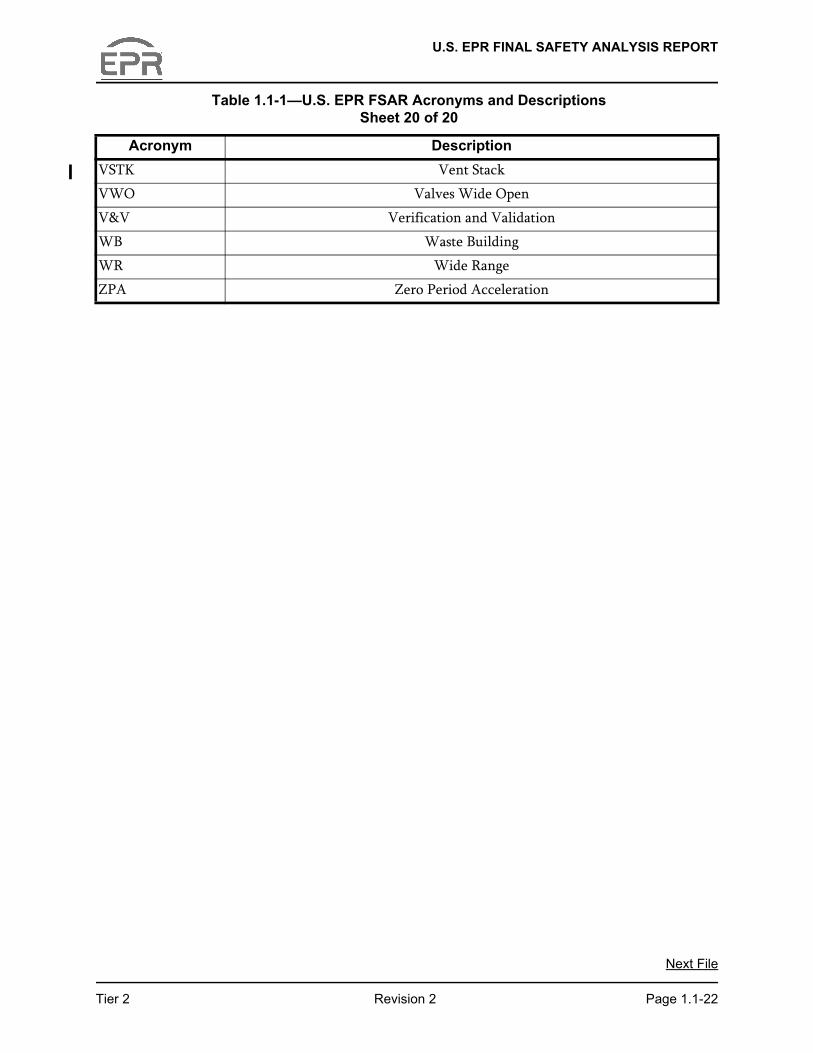
VSTK Vent Stack
VWO Valves Wide Open
V&V Verification and Validation
WB Waste Building
WR Wide Range
ZPA Zero Period Acceleration
Table 1.1-1—U.S. EPR FSAR Acronyms and Descriptions Sheet 20 of 20
Acronym Description
Next File
Tier 2 Revision 2 Page 1.1-22