Embed Size (px)
Citation preview
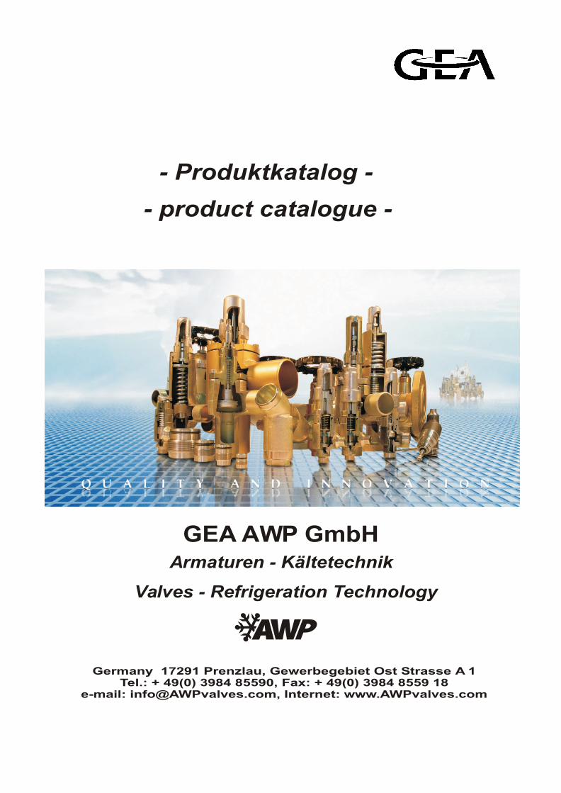
Armaturen - Kältetechnik
Germany 17291 Prenzlau, Gewerbegebiet Ost Strasse A 1Tel.: + 49(0) 3984 85590, Fax: + 49(0) 3984 8559 18
e-mail: [email protected], Internet: www.AWPvalves.com
GEA AWP GmbH
Valves - Refrigeration Technology
- Produktkatalog -
- product catalogue -
Anfrageinquiry
Nachrichtmessage
Bestellungorder
sonstigeother
An : GEA AWP Kälte Klima Armaturen GmbH Gewerbegebiet Ost - Straße A 1 17291 Prenzlau
Telefon: +49 (0) 3984 / 8559-0 Telefax: +49 (0) 3984 / 8559-18 e-mail: [email protected] Internet: www.AWPvalves.com
Von / from :
Bearbeiter / contact :
Telefon : Telefax : Datum / date :
Betreff /subject :
- Germany -
01.01.2009
AbsperrventileShut off valves
HRSAVRAVB
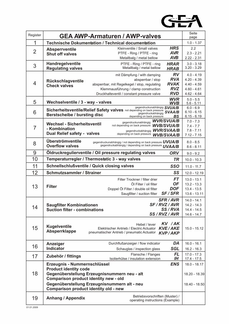
GEA AWP-Armaturen / AWP-valvesSeitepage
Technische Dokumentation / Technical documentation
Metallbalg / metal bellow
PTFE - Ring / PTFE - ring
Kleinventile / Small valves 2
Register
1 1.0 - 1.37
HandregelventileRegulating valves
HRARHRAB
PTFE - Ring / PTFE - ringMetallbalg / metal bellow 3
2.2
3.0 - 3.183.20 - 3.29
2.3 - 2.21
2.22 - 2.31
RückschlagventileCheck valves
RVRVA
RVAKRVZRVDDruckhalteventil / constant pressure valve
Klemmausführung / clamp construction
absperrbar, mit Regelkegel / stop, regulating
absperrbar / stop
mit Dämpfung / with damping
4
4.0 - 4.19
4.20 - 4.39
Wechselventile / 3 - way - valves WVB 5 5.6 - 5.11
Sicherheitsventile/Relief Safety valvesBerstscheibe / bursting disc
SVUA/BSVAA/B
BS
gegendruckunabhängig not depending on back pressure
gegendruckabhängig depending on back pressure
6 6.10 - 6.15
Wechsel - Sicherheitsventil - KombinationDual Relief safety - valves
WVR/SVUA/BWVB/SVUA/BWVR/SVAA/BWVB/SVAA/B
gegendruckunabhängig not depending on back pressure
77.12 - 7.15
ÜberströmventileOverflow valves
UVUA/BUVAA/B
gegendruckunabhängig / not depending on back pressuregegendruckabhängig / depending on back pressure 8
8.6 - 8.11
Öldruckregulierventile / Oil pressure regulating valves ORV 9 9.0 - 9.2
Temperaturregler / Thermostatic 3 - way valves TR10 10.0 - 10.3
Schmutzsammler / Strainer SS12 12.0 - 12.19
Filter
FTOF
DOFSF / SFR
13
13.0 - 13.1
Schnellschlußventile / Quick closing valves SSO11 11.0 - 11.7
Saugfilter / suction filter
Doppel Öl Filter / double oil filter
Öl Filter / oil filter
Filter Trockner / filter drier
Saugfilter KombinationenSuction filter - combinations
SFR / AVRSF / RVZ / AVR
SS / RVASS / RVZ / AVR
14
14.0 - 14.1
15
AnzeigerIndicator SGL
DA16
16.0 - 16.1
Schauglas / inspection glass
Durchflußanzeiger / flow indicator
Zubehör / fittings FL17 17.0 - 17.3
Gegenüberstellung Erzeugnisnummern alt - neuComparison product identity old - new
Gegenüberstellung Erzeugnisnummern neu - altComparison product identity new - old
Product identity codeErzeugnis - Nummernschlüssel ENS
18
18.0 - 18.17
Anhang / Appendix19 Betriebsvorschriften (Muster) / operating instructions (Example)
14.2 - 14.3
14.4 - 14.5
14.6 - 14.7
13.2 - 13.3
13.4 - 13.5
13.6 - 13.11
4.40 - 4.59
4.60 - 4.61
8.0 - 8.5
7.4 - 7.7
6.0 - 6.9
16.2 - 16.3
18.20 - 18.39
18.40 - 18.50
4.62 - 4.64
WVR 5.0 - 5.5
7.8 - 7.11
7.0 - 7.3
gegendruckabhängigdepending on back pressure
Flansche / Flanges
IH 17.4 - 17.5Isolierhülse / insulation extension
01.01.2009
6.15 - 6.19
Kugelventile Absperrklappe
Hebel / lever Elektrischer Antrieb / Electric Actuator
pneumatischer Antrieb / pneumatic Actuator
KV KVEKVP
/ AK / AKE/ AKP
15.0 - 15.12

Notizen / notice
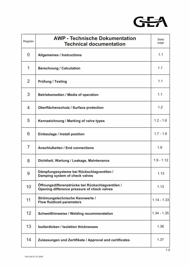
AWP - Technische DokumentationTechnical documentation
Seitepage
Allgemeines / Instructions
Register
1
1.1
Berechnung / Calculation
2
1.1
Prüfung / Testing
3
1.1
Betriebsmedien / Media of operation
4
1.1
Oberflächenschutz / Surface protection
5
1.2
Kennzeichnung / Marking of valve types
6
1.2 - 1.6
Einbaulage / Install position
7
1.7 - 1.8
Anschlußarten / End connections
8
1.9
Dichtheit, Wartung / Leakage, Maintenance
9
1.9 - 1.12
Dämpfungssysteme bei Rückschlagventilen /Damping system of check valves
10
1.13
Öffnungsdifferenzdrücke bei Rückschlagventilen /Opening difference pressure of check valves
11
1.13
Strömungstechnische Kennwerte /Flow fluidiced parameters
12
1.14 - 1.33
Schweißhinweise / Welding recommendation
13
1.34 - 1.35
Isolierdicken / Isolation thicknesses
14
1.36
Zulassungen und Zertifikate / Approval and certificates 1.37
0
1.0
Tech Dok 01.01.2009
Wichtige Hinweise zum Einbau, Bedienung, Service (Ersatzteile) von AWP - Produkten befinden in den jeweiligen Betriebsvorschriften.
Die detaillierten Betriebsvorschriften können für jedes AWP - Produktangefordert werden.
Eine Auswahl befindet sich im Anhang des AWP - Produktkataloges.
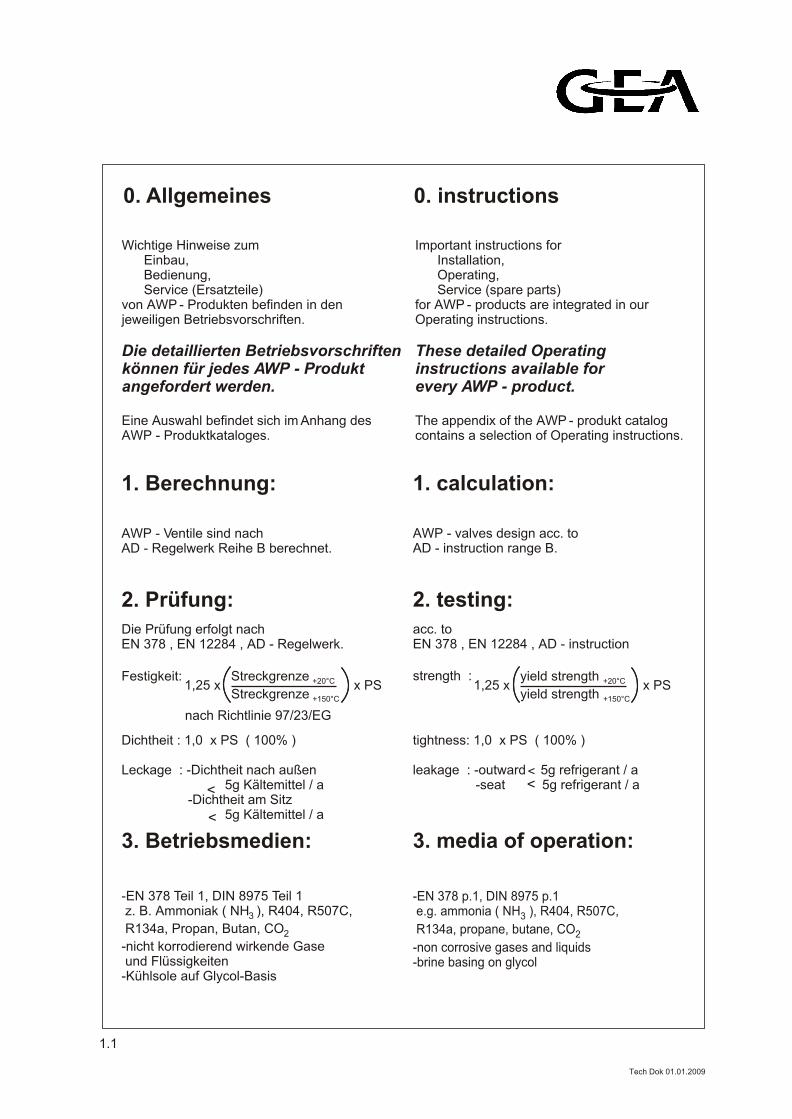
0. Allgemeines 0. instructions
Important instructions for Installation, Operating, Service (spare parts) for AWP - products are integrated in our Operating instructions.
These detailed Operating instructions available forevery AWP - product.
The appendix of the AWP - produkt catalog contains a selection of Operating instructions.
1. Berechnung: 1. calculation:
AWP - Ventile sind nachAD - Regelwerk Reihe B berechnet.
AWP - valves design acc. toAD - instruction range B.
2. Prüfung: 2. testing:
Die Prüfung erfolgt nachEN 378 , EN 12284 , AD - Regelwerk.
acc. toEN 378 , EN 12284 , AD - instruction
Dichtheit : 1,0 x PS ( 100% )
Leckage : -Dichtheit nach außen 5g Kältemittel / a -Dichtheit am Sitz 5g Kältemittel / a
tightness: 1,0 x PS ( 100% )
leakage : -outward 5g refrigerant / a -seat 5g refrigerant / a <
<
<<
3. Betriebsmedien: 3. media of operation:
-EN 378 Teil z. B. Ammoniak ( NH ), R404, R507C,3
R134a,
-nicht korrodierend wirkende
-Kühlsole auf Glycol-Basis
1, DIN 8975 Teil 1
Propan, Butan, CO2
Gase und Flüssigkeiten
-EN 378 p.1, DIN 8975 p.1 e.g. ammonia ( NH ), R404, R507C, 3
R134a, propane, butane, CO 2
-non corrosive gases and liquids-brine basing on glycol
1.1
Tech Dok 01.01.2009
Streckgrenze +150°C
Festigkeit:x PS1,25 x
Streckgrenze +20°C
nach Richtlinie 97/23/EG
strength :
yield strength +150°C
x PS1,25 xyield strength +20°C
4. Oberflächenschutz: 4. surface protection:
-Rostschutzgrundierung geeignet für alle Farbsysteme auf 2 - Komponenten - Epoxydharz - Basis-andere Farbsysteme auf Anfrage
-anticorrosive paint suitable for all colour systems based on 2 - components - epoxy resin-other colour systems upon request
5. Kennzeichnung der Ventiltypen:
5. marking of valve types:
Die Kennzeichnung der Ventile erfolgtdauerhaft auf dem Gehäuse und / oder auf einem Typenschild.
The marking of the valves is durablefixed on a body and / or on a valve plate.
-Für einen Langzeitkorrosionsschutz ist ein dauerhaftendes Anstrichsystem notwendig.
-For long-life protection futher paint sytem necessary.
UVA / UVU
overflow valves
SSO
quick - closing valves
SS
strainers
RV RVA / RVAK / RVZ
check valves
HRAR / HRAB
regulating valves
AVR / AVB
shut off valves
UVA / UVU
Überströmventile
SSO
Schnellschlußventile
SS
Schmutzsammler
RV / RVA / RVAK / RVZ
Rückschlagventile
HRAR / HRAB
Regelventile
AVR / AVB
Absperrventile
1.2
WVB / WVR
3 - way - valvesWVB / WVR
Wechselventile
TR
thermostatic 3-way valvesTR
Temperaturregler
Tech Dok 01.01.2009
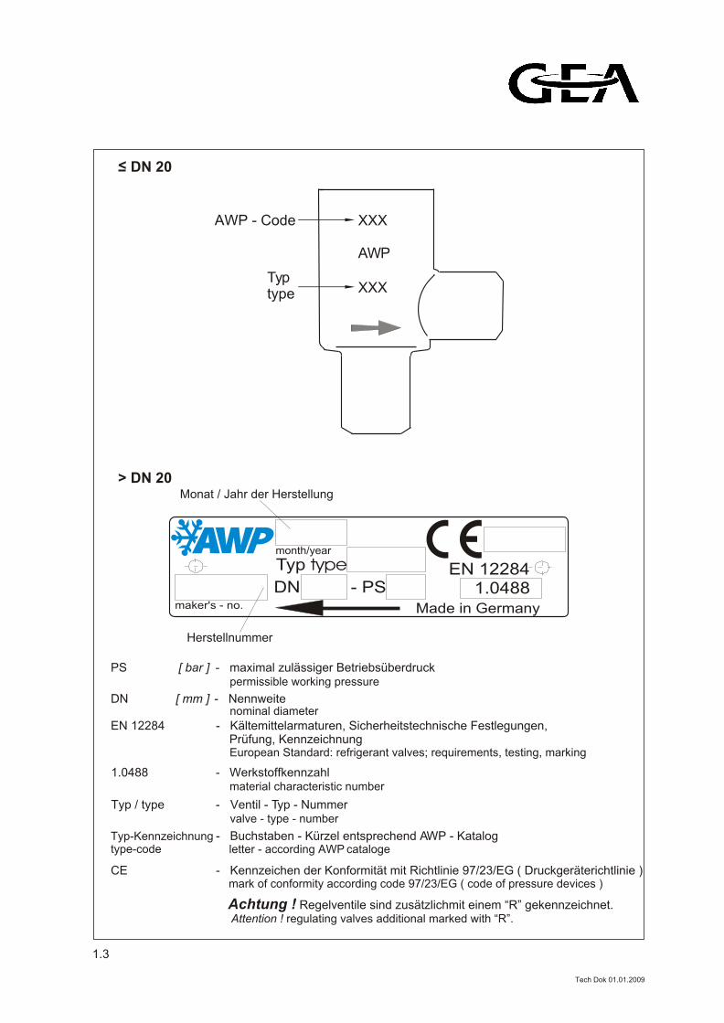
Monat / Jahr der Herstellung
Herstellnummer
PS [ bar ] - maximal zulässiger Betriebsüberdruck
nominal diameterDN [ mm ] - Nennweite
EN 12284
permissible working pressure
- 1.0488 Werkstoffkennzahlmaterial characteristic number
- Typ / type Ventil - Typ - Nummervalve - type - number
month/year
Typ type EN 12284DN - PS
maker's - no. Made in Germany
1.0488
Typ-Kennzeichnungtype-code
- Kältemittelarmaturen, Sicherheitstechnische Festlegungen, Prüfung, Kennzeichnung European Standard: refrigerant valves; requirements, testing, marking
- Buchstaben - Kürzel entsprechend AWP - Katalog letter - according AWP cataloge
1.3
CE - Kennzeichen der Konformität mit Richtlinie 97/23/EG ( Druckgeräterichtlinie ) mark of conformity according code 97/23/EG ( code of pressure devices )
Achtung ! Regelventile sind zusätzlichmit einem “R” gekennzeichnet. Attention ! regulating valves additional marked with “R”.
> DN 20
20DN <
AWP - Code
Typtype
XXX
AWP
XXX
Tech Dok 01.01.2009
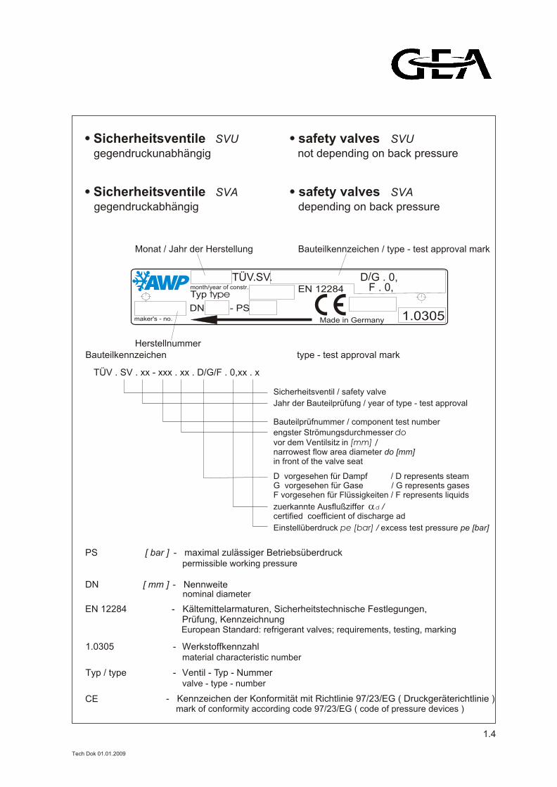
gegendruckabhängig
SVA Sicherheitsventile
gegendruckunabhängig
SVUSicherheitsventile
depending on back pressure
SVA
not depending on back pressure
SVUsafety valves
safety valves
Herstellnummer
Monat / Jahr der Herstellung Bauteilkennzeichen / type - test approval mark
/TÜV.SV. D G . 0,month/year of constr. Typ type
EN 12284
DN - PSmaker's - no. Made in Germany
F . 0,
1.0305
PS [ bar ] - maximal zulässiger Betriebsüberdruck
nominal diameterDN [ mm ] - Nennweite
EN 12284
permissible working pressure
- 1.0305 Werkstoffkennzahlmaterial characteristic number
- Typ / type Ventil - Typ - Nummervalve - type - number
Bauteilkennzeichen
TÜV . SV . xx - xxx . xx . D/G/F . 0,xx . x
Sicherheitsventil / safety valve
Jahr der Bauteilprüfung / year of type - test approval
G vorgesehen für Gase / G represents gasesF vorgesehen für Flüssigkeiten / F represents liquids
D vorgesehen für Dampf / D represents steam
Bauteilprüfnummer / component test number
zuerkannte Ausflußziffer d / certified coefficient of discharge ad
Einstellüberdruck pe [bar] / excess test pressure pe [bar]
engster Strömungsdurchmesser dovor dem Ventilsitz in [mm] /narrowest flow area diameter do [mm] in front of the valve seat
type - test approval mark
CE
- Kältemittelarmaturen, Sicherheitstechnische Festlegungen, Prüfung, Kennzeichnung European Standard: refrigerant valves; requirements, testing, marking
- Kennzeichen der Konformität mit Richtlinie 97/23/EG ( Druckgeräterichtlinie ) mark of conformity according code 97/23/EG ( code of pressure devices )
1.4
Tech Dok 01.01.2009
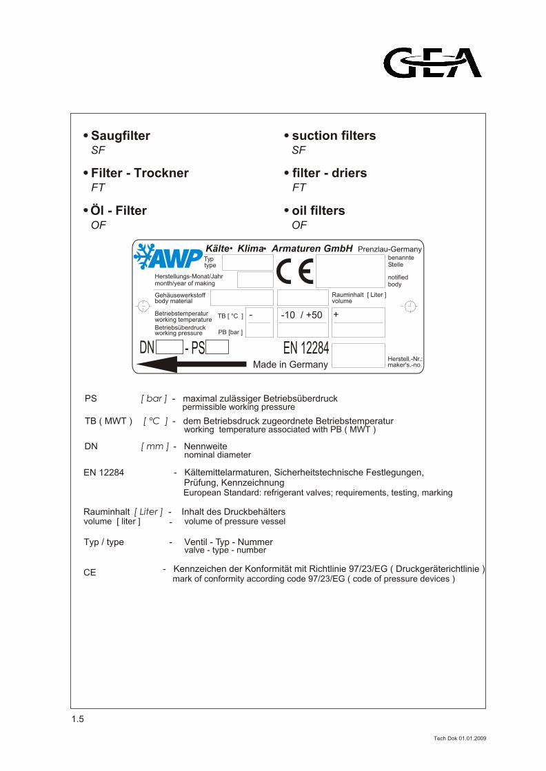
OF
Öl - Filter
FT
Filter - Trockner
SF
Saugfilter
oil filters
FT
suction filters
TB ( MWT ) [ °C ] - dem Betriebsdruck zugeordnete Betriebstemperatur
permissible working pressurePS [ bar ] - maximal zulässiger Betriebsüberdruck
working temperature associated with PB ( MWT )
volume of pressure vesselRauminhalt [ Liter ] - Inhalt des Druckbehälters
nominal diameterDN [ mm ] - Nennweite
EN 12284
- Typ / type Ventil - Typ - Nummervalve - type - number
volume [ liter ] -
SF
filter - driers
OF
DN - PS EN 12284Made in Germany
Kälte Klima Armaturen GmbH Prenzlau-Germany
Herstellungs-Monat/Jahr
Betriebstemperatur
Betriebsüberdruck
Rauminhalt [ Liter ]Gehäusewerkstoff
Typ
month/year of making
working temperature
working pressure
benannteStelle
notifiedbody
volumebody material
Herstell.-Nr.:maker's.-no.
type
TB [ °C ]
PB [bar ]
-10 / +50 +-
CE
- Kältemittelarmaturen, Sicherheitstechnische Festlegungen, Prüfung, Kennzeichnung European Standard: refrigerant valves; requirements, testing, marking
- Kennzeichen der Konformität mit Richtlinie 97/23/EG ( Druckgeräterichtlinie ) mark of conformity according code 97/23/EG ( code of pressure devices )
1.5
Tech Dok 01.01.2009
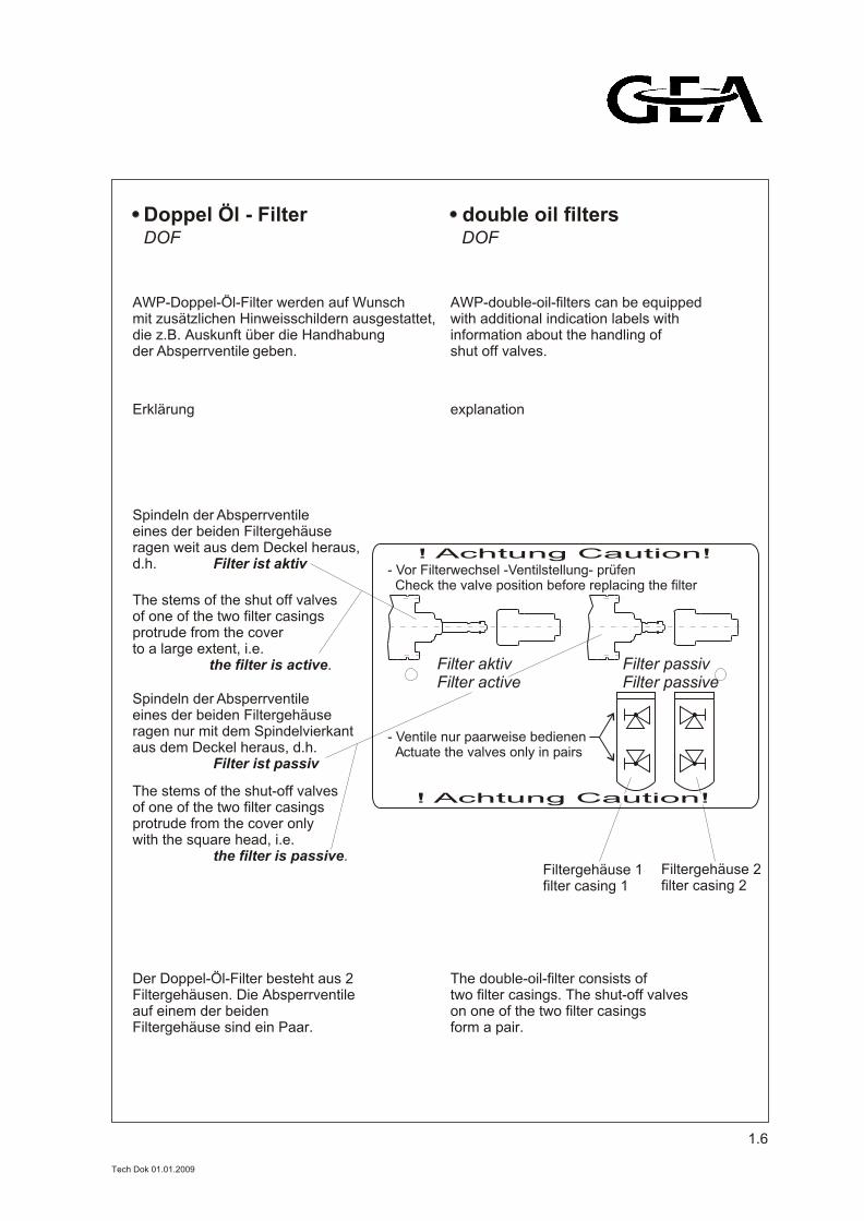
Doppel Öl - Filter double oil filters
AWP-Doppel-Öl-Filter werden auf Wunsch mit zusätzlichen Hinweisschildern ausgestattet,die z.B. Auskunft über die Handhabung der Absperrventile geben.
AWP-double-oil-filters can be equippedwith additional indication labels with information about the handling of shut off valves.
! Achtung Caution!
! Achtung Caution!
- Ventile nur paarweise bedienen Actuate the valves only in pairs
Filter aktivFilter active
Filter passivFilter passive
- Vor Filterwechsel -Ventilstellung- prüfen Check the valve position before replacing the filter
Erklärung
Spindeln der Absperrventileeines der beiden Filtergehäuseragen weit aus dem Deckel heraus,d.h. Filter ist aktiv
Spindeln der Absperrventileeines der beiden Filtergehäuseragen nur mit dem Spindelvierkantaus dem Deckel heraus, d.h. Filter ist passiv
The stems of the shut off valvesof one of the two filter casingsprotrude from the coverto a large extent, i.e. the filter is active.
The stems of the shut-off valvesof one of the two filter casingsprotrude from the cover onlywith the square head, i.e. the filter is passive.
Filtergehäuse 1filter casing 1
Filtergehäuse 2filter casing 2
explanation
Der Doppel-Öl-Filter besteht aus 2 Filtergehäusen. Die Absperrventile auf einem der beidenFiltergehäuse sind ein Paar.
The double-oil-filter consists oftwo filter casings. The shut-off valveson one of the two filter casingsform a pair.
DOF DOF
1.6
Tech Dok 01.01.2009
RV, RVA, RVAK, RVZ
RückschlagventileRV, RVA, RVAK, RVZ
check valves
-beliebig-Bei Einbau in senkrechten Leitungen unbedingt Strömungsrichtung bei AWP bekannt geben!
-in any position-At installation in vertical pipelines please contact AWP related to flow direction!
WVB / SVA, WVB / SVU
ventil - Kombinationen
Wechsel - Sicherheits-
UVA / UVU
Überströmventile
SVA / SVU
Sicherheitsventile
WVB / SVA, WVB / SVU
combinations
dual safety - valve
UVA / UVU
overflow valves
SVA / SVU
safety valves
-senkrecht nach EN 378 -vertical according to EN 378
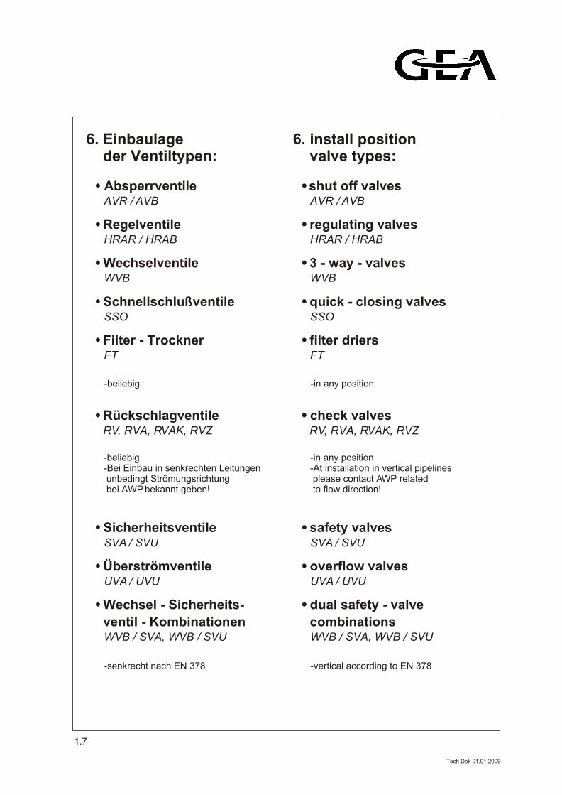
6. Einbaulage der Ventiltypen:
6. install position valve types:
FT
Filter - Trockner
SSO
Schnellschlußventile
WVB
Wechselventile
HRAR / HRAB
Regelventile
AVR / AVB
Absperrventile
FT
filter driers
SSO
quick - closing valves
WVB
3 - way - valves
HRAR / HRAB
regulating valves
AVR / AVB
shut off valves
-beliebig -in any position
1.7
Tech Dok 01.01.2009
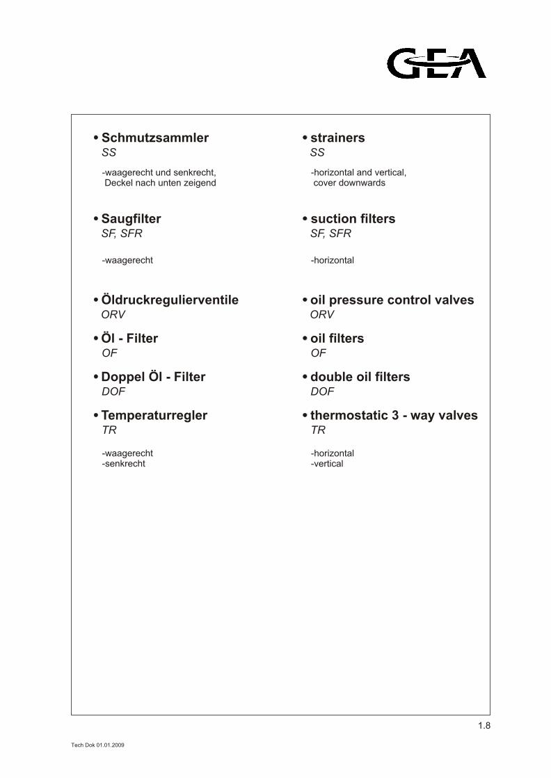
SS
SchmutzsammlerSS
strainers
-waagerecht und senkrecht, Deckel nach unten zeigend
-horizontal and vertical, cover downwards
SF, SFR
SaugfilterSF, SFR
suction filters
-waagerecht -horizontal
TR
Temperaturregler
DOF
Doppel Öl - Filter
OF
Öl - Filter
ORV
Öldruckregulierventile
TR
thermostatic 3 - way valves
DOF
double oil filters
OF
oil filters
ORV
oil pressure control valves
-waagerecht-senkrecht
-horizontal-vertical
1.8
Tech Dok 01.01.2009
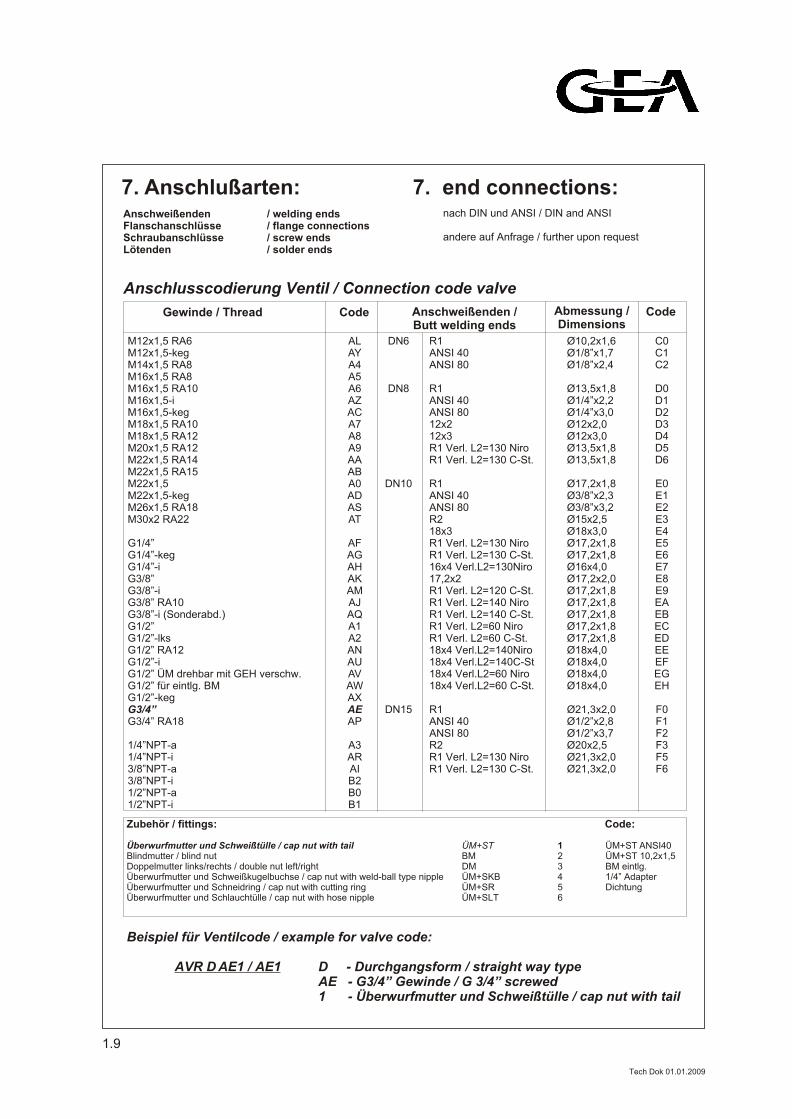
Gewinde / Thread Code Anschweißenden /Butt welding ends
Abmessung /Dimensions
Code
ALAYA4A5A6AZACA7A8A9AAABA0ADASAT
AFAGAHAKAMAJAQA1A2ANAUAVAWAXAEAP
A3ARAIB2B0B1
M12x1,5 RA6M12x1,5-kegM14x1,5 RA8M16x1,5 RA8M16x1,5 RA10M16x1,5-iM16x1,5-kegM18x1,5 RA10M18x1,5 RA12M20x1,5 RA12M22x1,5 RA14M22x1,5 RA15M22x1,5M22x1,5-kegM26x1,5 RA18M30x2 RA22
G1/4”G1/4”-kegG1/4”-iG3/8”G3/8”-iG3/8” RA10G3/8”-i (Sonderabd.)G1/2”G1/2”-lksG1/2” RA12G1/2”-iG1/2” ÜM drehbar mit GEH verschw.G1/2” für eintlg. BMG1/2”-kegG3/4”G3/4” RA18
1/4”NPT-a1/4”NPT-i3/8”NPT-a3/8”NPT-i1/2”NPT-a1/2”NPT-i
DN6
DN8
DN10
DN15
R1ANSI 40ANSI 80
R1ANSI 40ANSI 8012x212x3R1 Verl. L2=130 NiroR1 Verl. L2=130 C-St.
R1ANSI 40ANSI 80R218x3R1 Verl. L2=130 NiroR1 Verl. L2=130 C-St.16x4 Verl.L2=130Niro17,2x2R1 Verl. L2=120 C-St.R1 Verl. L2=140 NiroR1 Verl. L2=140 C-St.R1 Verl. L2=60 NiroR1 Verl. L2=60 C-St.18x4 Verl.L2=140Niro18x4 Verl.L2=140C-St18x4 Verl.L2=60 Niro18x4 Verl.L2=60 C-St.
R1ANSI 40ANSI 80R2R1 Verl. L2=130 NiroR1 Verl. L2=130 C-St.
Ø10,2x1,6Ø1/8”x1,7Ø1/8”x2,4
Ø13,5x1,8Ø1/4”x2,2Ø1/4”x3,0Ø12x2,0Ø12x3,0Ø13,5x1,8Ø13,5x1,8
Ø17,2x1,8Ø3/8”x2,3Ø3/8”x3,2Ø15x2,5Ø18x3,0Ø17,2x1,8Ø17,2x1,8Ø16x4,0Ø17,2x2,0Ø17,2x1,8Ø17,2x1,8Ø17,2x1,8Ø17,2x1,8Ø17,2x1,8Ø18x4,0Ø18x4,0Ø18x4,0Ø18x4,0
Ø21,3x2,0Ø1/2”x2,8Ø1/2”x3,7Ø20x2,5Ø21,3x2,0Ø21,3x2,0
C0C1C2
D0D1D2D3D4D5D6
E0E1E2E3E4E5E6E7E8E9EAEBECEDEEEFEGEH
F0F1F2F3F5F6
7. Anschlußarten: 7. end connections:Anschweißenden / welding endsFlanschanschlüsse / flange connectionsSchraubanschlüsse / screw endsLötenden / solder ends
Anschlusscodierung Ventil / Connection code valve
nach DIN und ANSI / DIN and ANSI
andere auf Anfrage / further upon request
1.9
Zubehör / fittings: Code:
Überwurfmutter und Schweißtülle / cap nut with tail ÜM+ST 1 ÜM+ST ANSI40Blindmutter / blind nut BM 2 ÜM+ST 10,2x1,5Doppelmutter links/rechts / double nut left/right DM 3 BM eintlg.Überwurfmutter und Schweißkugelbuchse / cap nut with weld-ball type nipple ÜM+SKB 4 1/4” AdapterÜberwurfmutter und Schneidring / cap nut with cutting ring ÜM+SR 5 DichtungÜberwurfmutter und Schlauchtülle / cap nut with hose nipple ÜM+SLT 6
Beispiel für Ventilcode / example for valve code:
AVR D AE1 / AE1 D - Durchgangsform / straight way typeAE - G3/4” Gewinde / G 3/4” screwed1 - Überwurfmutter und Schweißtülle / cap nut with tail
Tech Dok 01.01.2009
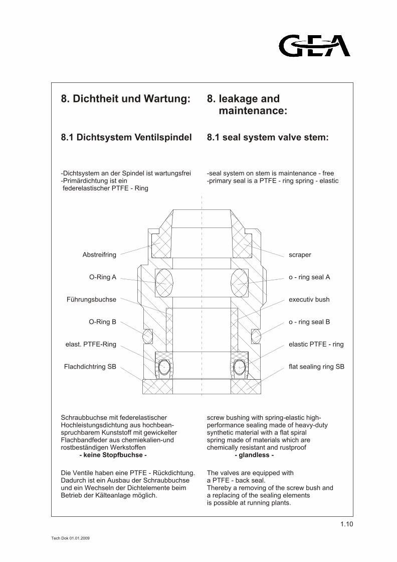
8. Dichtheit und Wartung: 8. leakage and maintenance:
8.1 Dichtsystem Ventilspindel
-Dichtsystem an der Spindel ist wartungsfrei-Primärdichtung ist ein federelastischer PTFE - Ring
8.1 seal system valve stem:
-seal system on stem is maintenance - free-primary seal is a PTFE - ring spring - elastic
Schraubbuchse mit federelastischer Hochleistungsdichtung aus hochbean-spruchbarem Kunststoff mit gewickelterFlachbandfeder aus chemiekalien-undrostbeständigen Werkstoffen
- keine Stopfbuchse -
screw bushing with spring-elastic high-performance sealing made of heavy-dutysynthetic material with a flat spiralspring made of materials which arechemically resistant and rustproof
- glandless -
Die Ventile haben eine PTFE - Rückdichtung.Dadurch ist ein Ausbau der Schraubbuchse und ein Wechseln der Dichtelemente beimBetrieb der Kälteanlage möglich.
The valves are equipped with a PTFE - back seal.Thereby a removing of the screw bush and a replacing of the sealing elements is possible at running plants.
Abstreifring
O-Ring A
Führungsbuchse
O-Ring B
elast. PTFE-Ring
Flachdichtring SB
scraper
o - ring seal A
executiv bush
o - ring seal B
elastic PTFE - ring
flat sealing ring SB
1.10
Tech Dok 01.01.2009
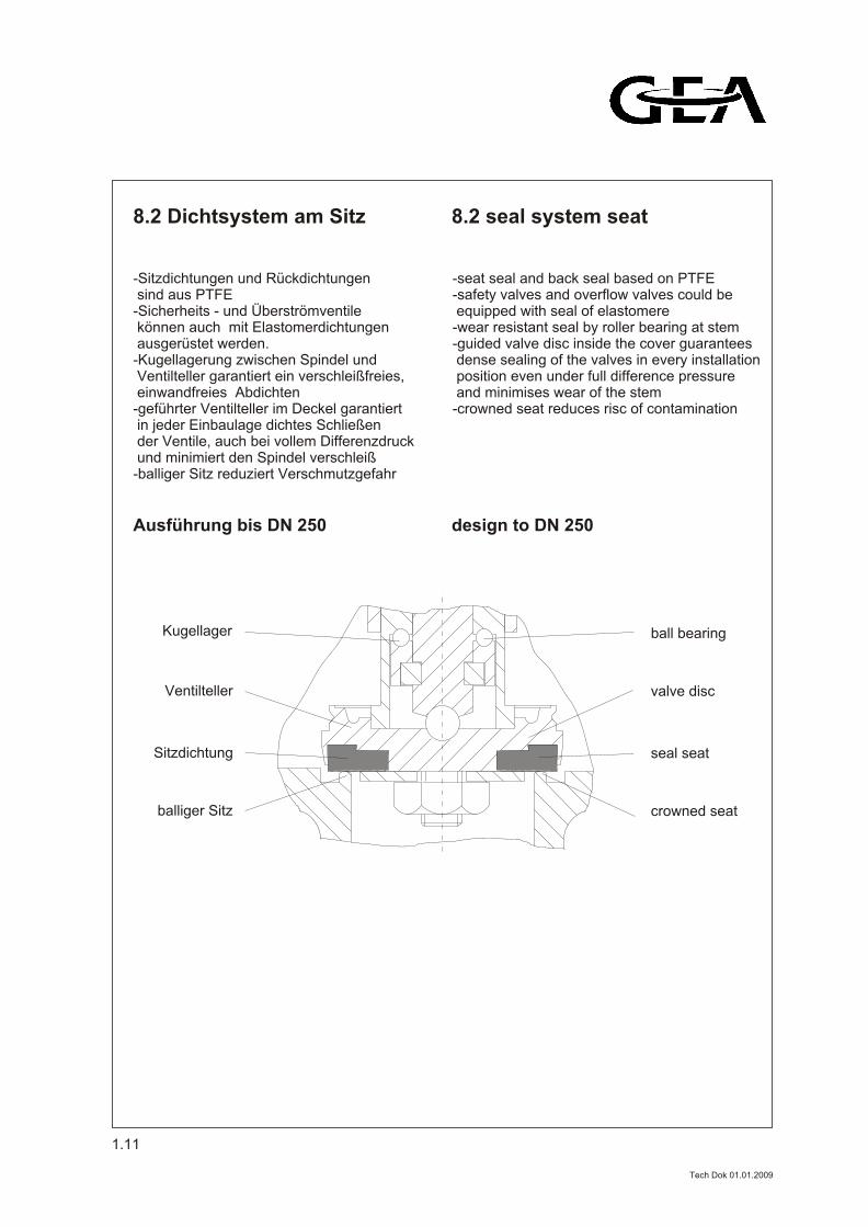
8.2 Dichtsystem am Sitz 8.2 seal system seat
-seat seal and back seal based on PTFE-safety valves and overflow valves could be equipped with seal of elastomere-wear resistant seal by roller bearing at stem-guided valve disc inside the cover guarantees dense sealing of the valves in every installation position even under full difference pressure and minimises wear of the stem-crowned seat reduces risc of contamination
-Sitzdichtungen und Rückdichtungen sind aus PTFE-Sicherheits - und Überströmventile können auch mit Elastomerdichtungen ausgerüstet werden.-Kugellagerung zwischen Spindel und Ventilteller garantiert ein verschleißfreies, einwandfreies Abdichten-geführter Ventilteller im Deckel garantiert in jeder Einbaulage dichtes Schließen der Ventile, auch bei vollem Differenzdruck und minimiert den Spindel verschleiß-balliger Sitz reduziert Verschmutzgefahr
balliger Sitz
Sitzdichtung
Ventilteller
crowned seat
seal seat
valve disc
Kugellager ball bearing
Ausführung bis DN 250 design to DN 250
1.11
Tech Dok 01.01.2009
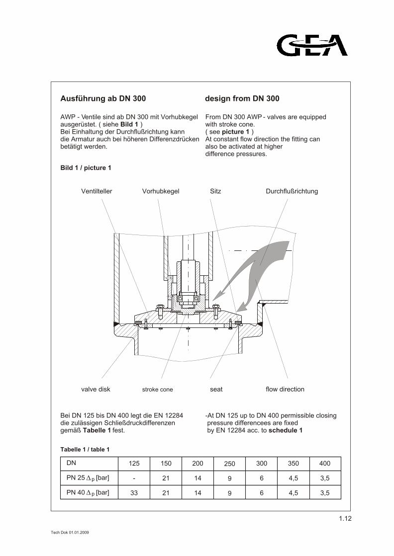
AWP - Ventile sind ab DN 300 mit Vorhubkegel ausgerüstet. ( siehe Bild 1 )Bei Einhaltung der Durchflußrichtung kann die Armatur auch bei höheren Differenzdrücken betätigt werden.
From DN 300 AWP - valves are equipped with stroke cone. ( see picture 1 )At constant flow direction the fitting can also be activated at higher difference pressures.
Ventilteller Vorhubkegel Sitz Durchflußrichtung
valve disk stroke cone seat flow direction
Bild 1 / picture 1
Ausführung ab DN 300 design from DN 300
Bei DN 125 bis DN 400 legt die EN 12284 die zulässigen Schließdruckdifferenzen gemäß Tabelle 1 fest.
-At DN 125 up to DN 400 permissible closing pressure differencees are fixed by EN 12284 acc. to schedule 1
DN
PN 25 [bar]
PN 40 [bar]
250
9
9
300
6
6
350
4,5
4,5
400
3,5
3,5
Tabelle 1 / table 1
125
-
33
150
21
21
200
14
14
p
1.12
p
Tech Dok 01.01.2009
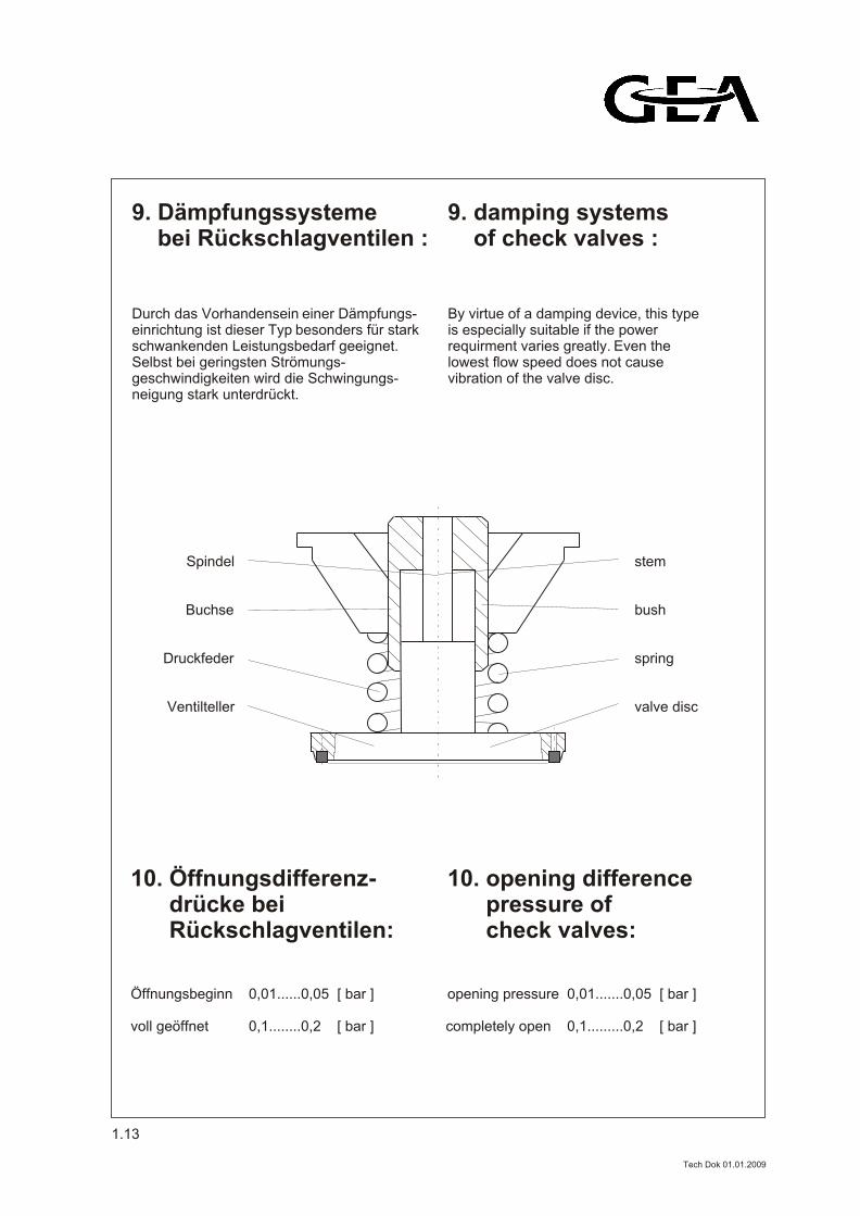
9. Dämpfungssysteme bei Rückschlagventilen :
9. damping systems of check valves :
Durch das Vorhandensein einer Dämpfungs-einrichtung ist dieser Typ besonders für starkschwankenden Leistungsbedarf geeignet.Selbst bei geringsten Strömungs-geschwindigkeiten wird die Schwingungs-neigung stark unterdrückt.
By virtue of a damping device, this typeis especially suitable if the powerrequirment varies greatly. Even thelowest flow speed does not cause
vibration of the valve disc.
Spindel
Buchse
Druckfeder
Ventilteller
stem
bush
spring
valve disc
10. Öffnungsdifferenz- drücke bei Rückschlagventilen:
10. opening difference pressure of check valves:
Öffnungsbeginn 0,01......0,05 [ bar ]
voll geöffnet 0,1........0,2 [ bar ] completely open 0,1.........0,2 [ bar ]
opening pressure 0,01.......0,05 [ bar ]
1.13
Tech Dok 01.01.2009
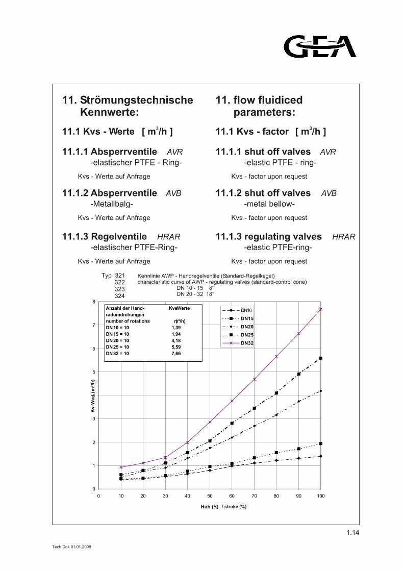
11. Strömungstechnische Kennwerte:
11. flow fluidiced parameters:
11.1 Kvs - Werte 11.1 Kvs - factor
AVR
-elastic PTFE - ring-
11.1.1 shut off valves
3[ m /h ] 3[ m /h ]
AVR
-elastischer PTFE - Ring-
11.1.1 Absperrventile
1.14
Kvs - Werte auf Anfrage Kvs - factor upon request
AVB
-Metallbalg-
11.1.2 Absperrventile AVB
-metal bellow-
11.1.2 shut off valves
Kvs - Werte auf Anfrage Kvs - factor upon request
HRAR
-elastischer PTFE-Ring-
11.1.3 Regelventile HRAR
-elastic PTFE-ring-
11.1.3 regulating valves
Kvs - Werte auf Anfrage Kvs - factor upon request
Kennlinie AWP - Handregelventile (Standard-Regelkegel)characteristic curve of AWP - regulating valves (standard-control cone) DN 10 - 15 8° DN 20 - 32 18°
Typ 321 322 323 324
/ stroke (%)
0
1
2
3
4
5
6
7
8
0 10 20 30 40 50 60 70 80 90 100
Hub (%)
Kv-W
ert
(m³/
h)
DN10
DN15
DN20
DN25
DN32
Anzahl der Hand- Kvs-Werte
radumdrehungen
number of rotations (m³/h)
DN 10 = 10 1,39
DN 15 = 10 1,94
DN 20 = 10 4,18
DN 25 = 10 5,59
DN 32 = 10 7,66
Tech Dok 01.01.2009
1.15
Hub (%)
0
0,1
0,2
0,3
0,4
0,5
0,6
0,7
0,8
0 10 20 30 40 50 60 70 80 90 100
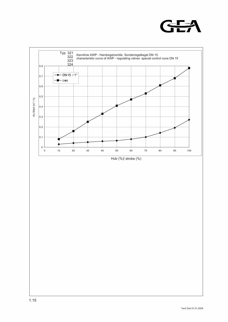
DN 15 / 1°
DN 15 / 3 °
Typ 321 322 323 324
3K
v-W
ert
(m
/ h
)
Kennlinie AWP - Handregelventile Sonderregelkegel DN 15characteristic curve of AWP - regulating valves special control cone DN 15
/ stroke (%)
Tech Dok 01.01.2009
1.16
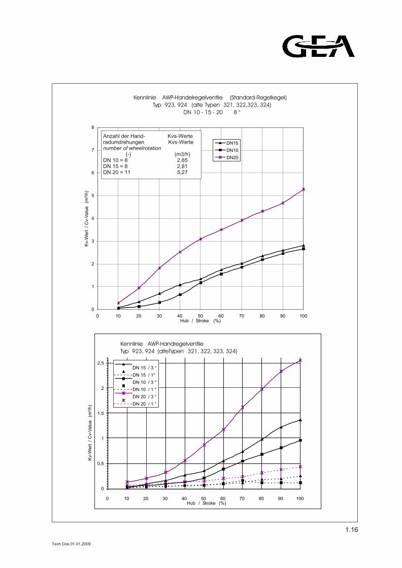
Kennlinie AWP-Handelregelventile (Standard-Regelkegel)
Typ 923, 924 (alte Typen 321, 322,323, 324)
DN 10 - 15 - 20 8 °
0
1
2
3
4
5
6
7
8
0 10 20 30 40 50 60 70 80 90 100Hub / Stroke (%)
Kv-
Wert
/
Cv-
Valu
e (
m³/
h)
DN15
DN10
DN20
Anzahl der Hand- Kvs-Werte
radumdrehungen Kvs-Value
number of wheelrotation
(-) (m³/h)
DN 10 = 8 2,65
DN 15 = 8 2,81
DN 2 0= 11 5,27
Anzahl der Hand- Kvs-Werteradumdrehungen Kvs-Wertenumber of wheelrotation (-) (m3/h)DN 10 = 8 2,65DN 15 = 8 2,81DN 20 = 11 5,27
0
0,5
1
1,5
2
2,5
0 10 20 30 40 50 60 70 80 90 100
DN 15 / 3 °
DN 15 / 1°
DN 10 / 3 °
DN 10 / 1 °
DN 20 / 3 °
DN 20 / 1 °
Kennlinie AWP-Handregelventile
Typ 923, 924 (alteTypen 321, 322, 323, 324)
Kv-
Wert
/
Cv-
Valu
e (
m³/
h)
Hub / Stroke (%)
Tech Dok 01.01.2009
0
2
4
6
8
10
12
14
16
0 10 20 30 40 50 60 70 80 90 100
Hub (%)
Kv
-We
rt(m
³/h
) DN10
DN20
DN32
DN25
DN15
DN 25
DN 32
DN 15
DN 10
DN 20
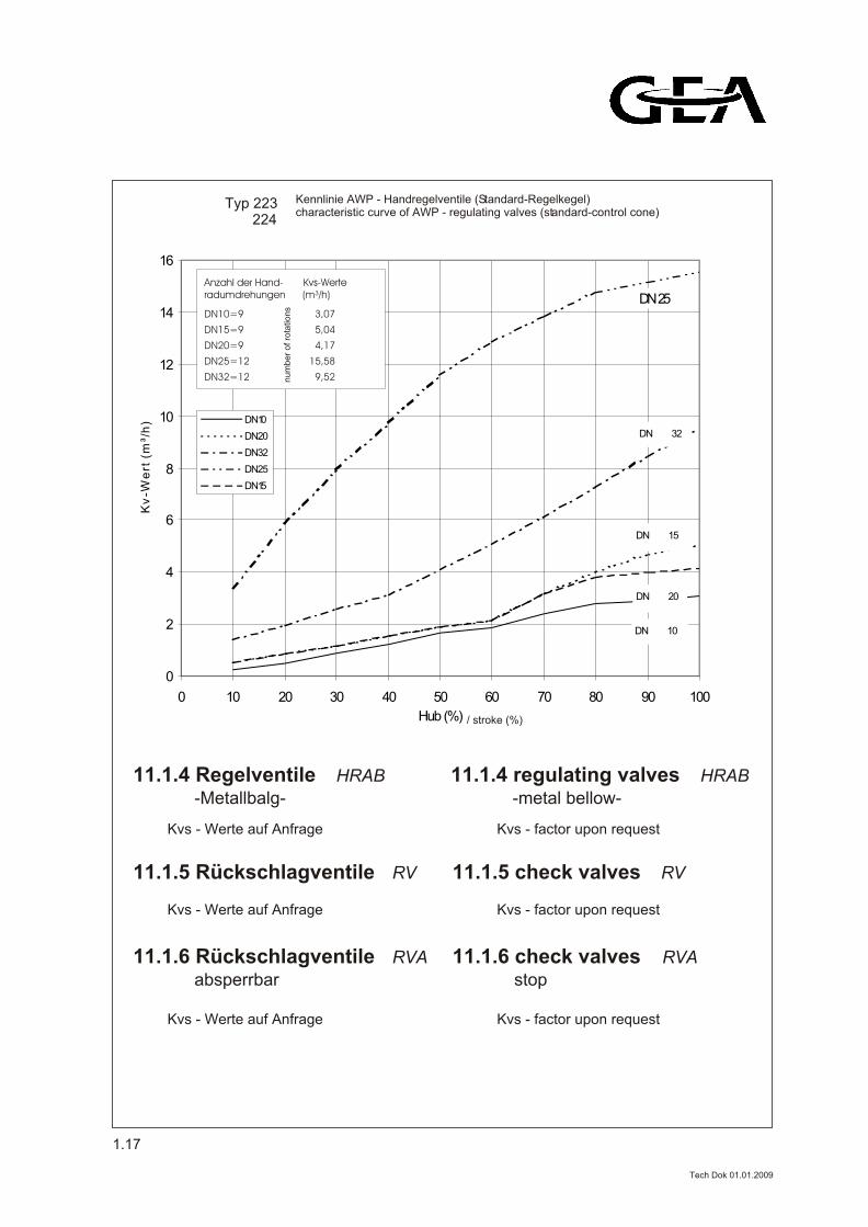
Typ 223 224
HRAB
-Metallbalg-
11.1.4 Regelventile HRAB
-metal bellow-
11.1.4 regulating valves
Kennlinie AWP - Handregelventile (Standard-Regelkegel)characteristic curve of AWP - regulating valves (standard-control cone)
/ stroke (%)
Kvs - Werte auf Anfrage Kvs - factor upon request
RV11.1.5 Rückschlagventile RV11.1.5 check valves
RVA
absperrbar
11.1.6 Rückschlagventile RVA
stop
11.1.6 check valves
Kvs - Werte auf Anfrage Kvs - factor upon request
Kvs - Werte auf Anfrage Kvs - factor upon request
1.17
Anzahl der Hand- Kvs-Werteradumdrehungen (m³/h)
DN10=9 3,07
DN15=9 5,04
DN20=9 4,17
DN25=12 15,58
DN32=12 9,52nu
mb
er
of ro
tatio
ns
Tech Dok 01.01.2009
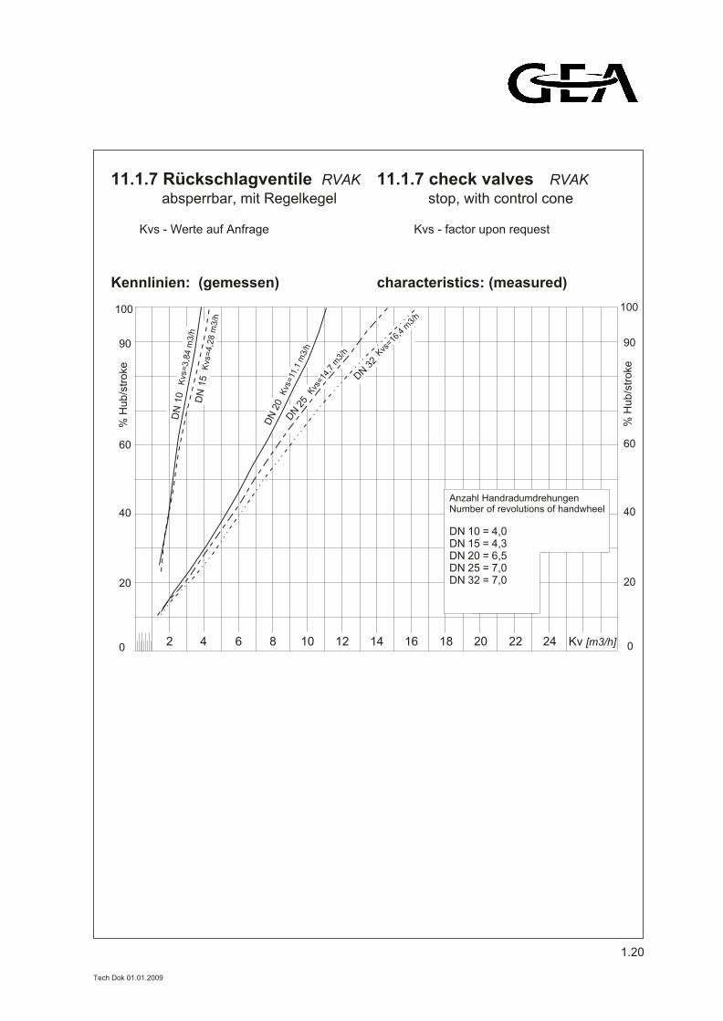
RVAK
absperrbar, mit Regelkegel
11.1.7 Rückschlagventile RVAK
stop, with control cone
11.1.7 check valves
characteristics: (measured)
% H
ub
/str
oke
% H
ub
/str
oke
0 0
20 20
40 40
60 60
90 90
100 100
2 4 6 8 10 12 14 16 18 20 22 24 Kv [m3/h]
DN
10
Kvs
=3,8
4 m
3/h
DN
15
DN
20
DN
25
DN 3
2
Kvs
=4,2
8 m
3/h
Kvs
=11
,1 m
3/h
Kvs
=14,
7 m
3/h Kvs
=16,4
m3/
h
Anzahl HandradumdrehungenNumber of revolutions of handwheel
DN 10 = 4,0DN 15 = 4,3DN 20 = 6,5DN 25 = 7,0DN 32 = 7,0
Kennlinien: (gemessen)
1.20
Kvs - Werte auf Anfrage Kvs - factor upon request
Tech Dok 01.01.2009
RVZ
in Klemmausführung
11.1.8 Rückschlagventile with clamp construction
11.1.8 check valves
SS
11.1.10 Schmutzsammler 11.1.10 strainer
RVZ
SS
WVB
11.1.9 Wechselventile 11.1.9 3 - way - valvesWVB
SS / RVA
Rückschlagventil
absperrbarem
mit angeschweißtem,
11.1.11 Saugfilterkombination
SS / RVA
check valve stop
with welded
11.1.11 suction filter combination
strainer
Schmutzsammler
1.21
Kvs - Werte auf Anfrage Kvs - factor upon request
Kvs - Werte auf Anfrage Kvs - factor upon request
Kvs - Werte auf Anfrage Kvs - factor upon request
Kvs - Werte auf Anfrage Kvs - factor upon request
SS / RVZ / AVR
und Absperrventil
rückschlagventil
Zwischenflansch-
mit angeflanschtem
SS / RVZ / AVR
and
check valve clamp
with flanged
shut off valve
SF
11.1.13 SaugfilterSF
11.1.13 suction filters
11.1.12 Saugfilterkombination 11.1.12 suction filter combination
Schmutzsammler strainer
Kvs - Werte auf Anfrage Kvs - factor upon request
Kvs - Werte auf Anfrage Kvs - factor upon request
Tech Dok 01.01.2009
SFR
Rückschlagventil
mit integriertem
11.1.14 Saugfilter
SFR
check valve
equipped with
11.1.14 suction filters
SFR / AVR
Absperrventil
angeflanschtem
Rückschlagventil und
mit integriertem
SFR / AVR
shut off valve
flanged
check valve and
with integrated
11.1.15 Saugfilterkombination 11.1.15 suction filter combination
Saugfilter suction filter
1.22
Kvs - Werte auf Anfrage Kvs - factor upon request
Kvs - Werte auf Anfrage Kvs - factor upon request
SF / RVZ / AVR
und Absperrventil
rückschlagventil
Zwischenflansch-
mit angeflanschtem
SF / RVZ / AVR
and
check valve clamp
with flanged
shut off valve
11.1.16 Saugfilterkombination 11.1.16 suction filter combination
Saugfilter suction filter
Kvs - Werte auf Anfrage Kvs - factor upon request
Tech Dok 01.01.2009
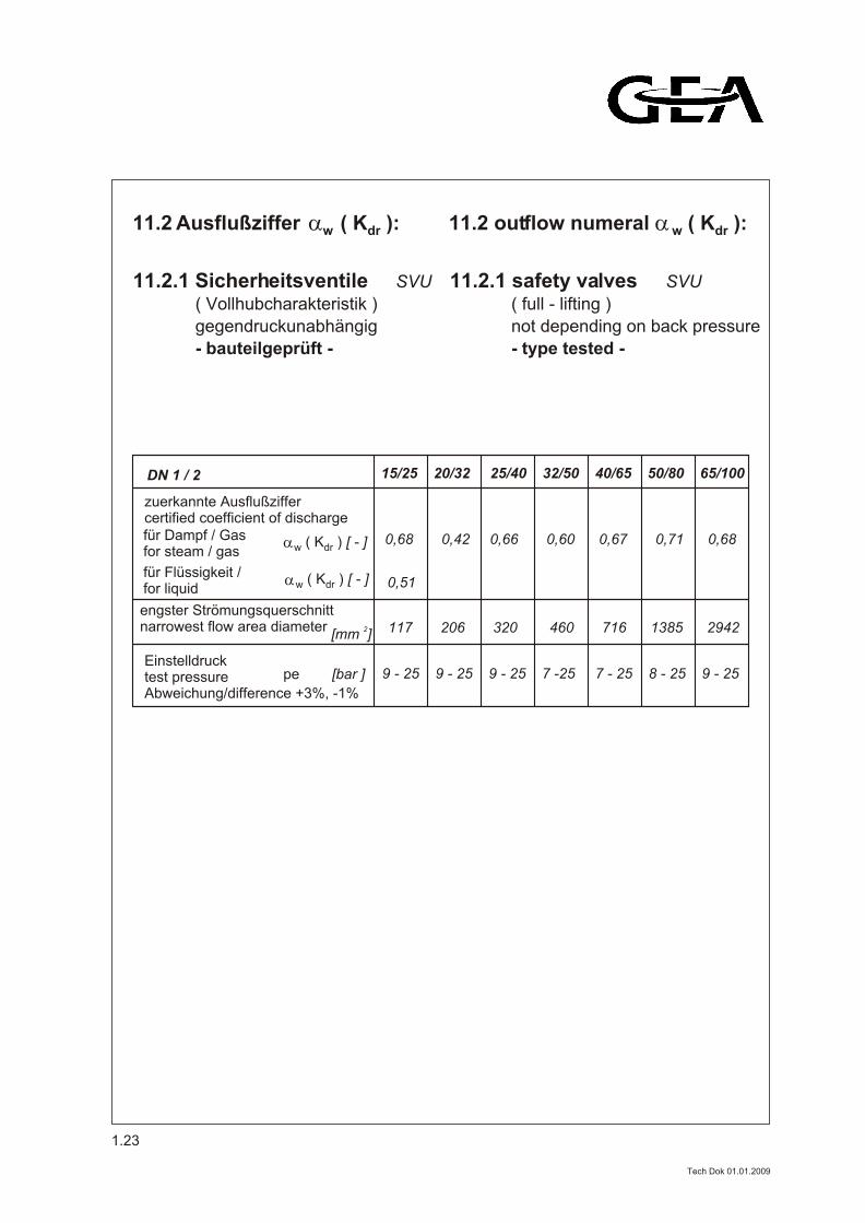
11.2 Ausflußziffer ( K ):w dr 11.2 outflow numeral ( K ):w dr
- bauteilgeprüft -
gegendruckunabhängig
( Vollhubcharakteristik )
11.2.1 Sicherheitsventile SVU
- type tested -
not depending on back pressure
( full - lifting )
11.2.1 safety valves SVU
15/25 20/32 25/40 32/50 40/65 50/80 65/100
zuerkannte Ausflußziffer certified coefficient of discharge
0,68 0,42 0,66 0,60 0,67 0,71 0,68
0,51
117 206 320 460 716 1385 2942
Einstelldruck pe [bar ]test pressure
Abweichung/difference +3%, -1%
9 - 25 9 - 25 9 - 25 7 -25 7 - 25 8 - 25 9 - 25
DN 1 / 2
( K ) [ - ]w drfür Dampf / Gas for steam / gas
für Flüssigkeit /for liquid
2[mm ]
( K ) [ - ]w dr
engster Strömungsquerschnittnarrowest flow area diameter
1.23
Tech Dok 01.01.2009
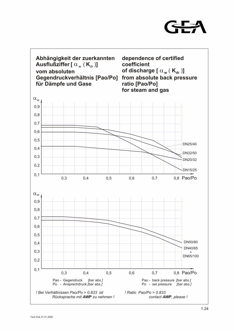
Abhängigkeit der zuerkannten Ausflußziffer [ ( K )] w dr
vom absoluten Gegendruckverhältnis [Pao/Po]für Dämpfe und Gase
dependence of certified coefficient of discharge [ ( K )] w dr
from absolute back pressure ratio [Pao/Po]for steam and gas
0,3 0,4 0,5 0,6 0,7 0,8 Pao/Po
0,9
0,8
0,7
0,6
0,5
0,4
0,3
0,2
0,1
w
Pao - Gegendruck [bar abs.]Po - Ansprechdruck [bar abs.]
Pao - back pressure [bar abs.]Po - set pressure [bar abs.]
! Bei Verhältnissen Pao/Po > 0,833 ist Rücksprache mit AWP zu nehmen !
! Ratio Pao/Po > 0,833 contact AWP, please !
0,3 0,4 0,5 0,6 0,7 0,8 Pao/Po
0,9
0,8
0,7
0,6
0,5
0,4
0,3
0,2
0,1
w
DN25/40
DN32/50
DN20/32
DN15/25
DN50/80
DN40/65+
DN65/100
1.24
Tech Dok 01.01.2009
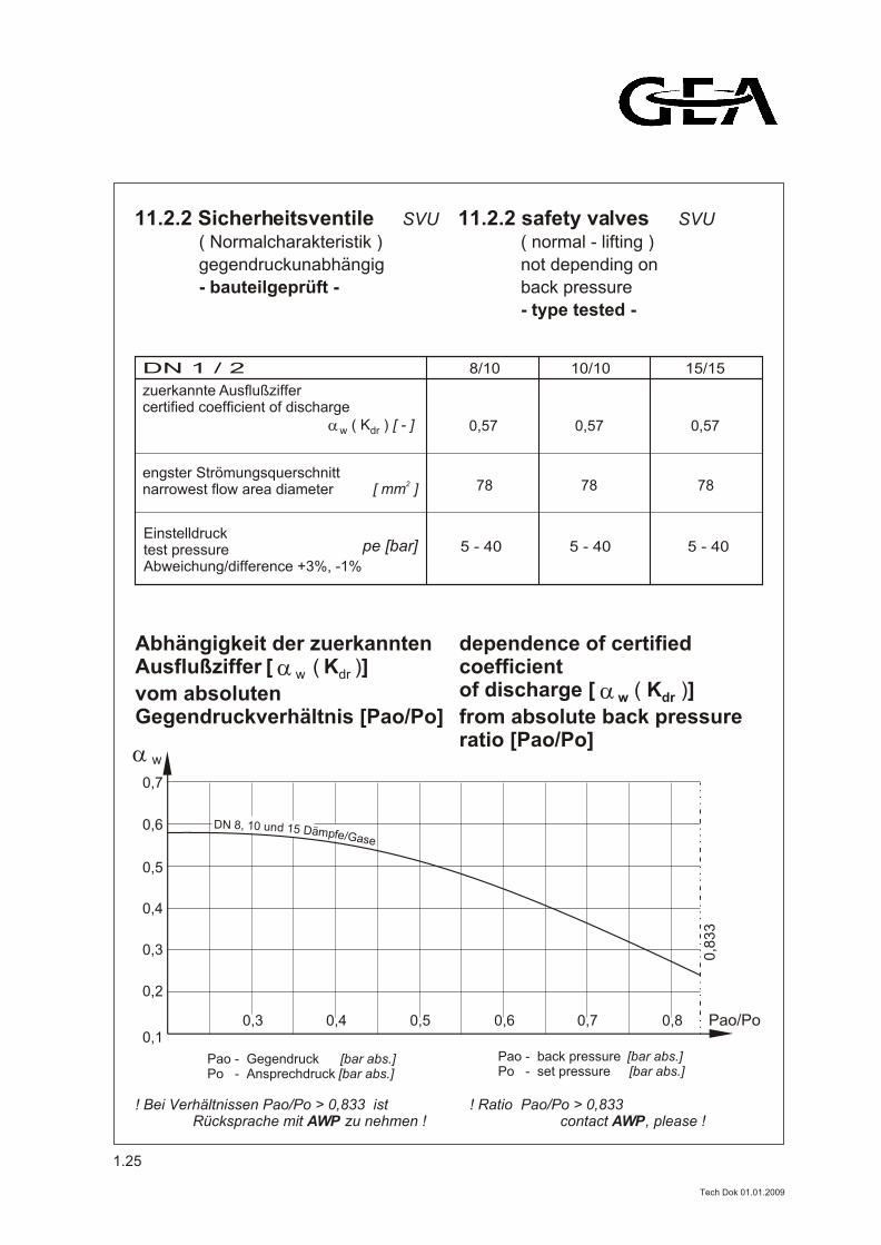
- bauteilgeprüft -
gegendruckunabhängig
( Normalcharakteristik )
11.2.2 Sicherheitsventile SVU
- type tested -
back pressure
not depending on
( normal - lifting )
11.2.2 safety valves SVU
8/10 10/10 15/15
zuerkannte Ausflußziffer certified coefficient of discharge
78 78 78
Einstelldruck test pressure Abweichung/difference +3%, -1%
5 - 40 5 - 40 5 - 40
DN 1 / 2
0,570,57 0,57
pe [bar]
2[ mm ]
0,3 0,4 0,5 0,6 0,7 0,80,1
0,2
0,3
0,4
0,5
0,6
0,7
0,8
33
w
Pao/Po
DN 8, 10 und 15 Dämpfe/Gase
Pao - Gegendruck [bar abs.]Po - Ansprechdruck [bar abs.]
Pao - back pressure [bar abs.]Po - set pressure [bar abs.]
! Bei Verhältnissen Pao/Po > 0,833 ist Rücksprache mit AWP zu nehmen !
! Ratio Pao/Po > 0,833 contact AWP, please !
( K ) [ - ] w dr
Abhängigkeit der zuerkannten Ausflußziffer [ ( K )] w dr
vom absoluten Gegendruckverhältnis [Pao/Po]
dependence of certified coefficient of discharge [ ( K )] w dr
from absolute back pressure ratio [Pao/Po]
engster Strömungsquerschnittnarrowest flow area diameter
1.25
Tech Dok 01.01.2009
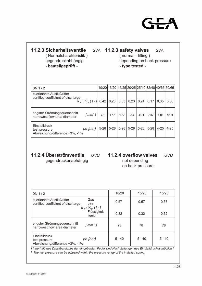
- bauteilgeprüft -
gegendruckabhängig
11.2.3 Sicherheitsventile SVA
- type tested -
depending on back pressure
11.2.3 safety valves SVA
gegendruckunabhängig
11.2.4 Überströmventile UVU
on back pressure
not depending
11.2.4 overflow valves UVU
0,360,35 0,17 0,24 0,23 0,33 0,20 0,42
919716 707 491 314 177 177 78
4-254-25 5-28 5-28 5-28 5-28 5-28 5-28
DN 1 / 2 50/6540/65 32/40 25/40 20/25 15/25 15/20 10/20
zuerkannte Ausflußziffer certified coefficient of discharge
Einstelldruck test pressure Abweichung/difference +3%, -1%
pe [bar]
2[ mm ]
( K ) [ - ] w dr
! Innerhalb des Druckbereiches der eingebauten Feder sind Nachstellungen des Einstelldruckes möglich !
0,57 0,570,57
78 78 78
5 - 40 5 - 40 5 - 40
DN 1 / 2 15/25 15/20 10/20
zuerkannte Ausflußziffer certified coefficient of discharge
Einstelldruck test pressure Abweichung/difference +3%, -1%
pe [bar]
2[ mm ]
0,32 0,32 0,32
Gasgas
Flüssigkeitliquid
( K ) [ - ] w dr
( Normalcharakteristik ) ( normal - lifting )
engster Strömungsquerschnittnarrowest flow area diameter
engster Strömungsquerschnittnarrowest flow area diameter
! The test pressure can be adjusted within the pressure range of the installed spring.
1.26
Tech Dok 01.01.2009
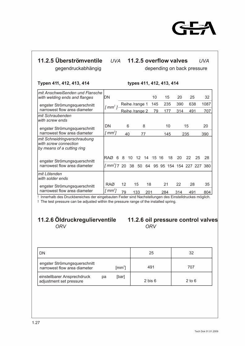
gegendruckabhängig
11.2.5 Überströmventile UVA
depending on back pressure
11.2.5 overflow valves UVA
ORV
Öldruckregulierventile 11.2.6 11.2.6 oil pressure control valves
25 32
2[mm ]
einstellbarer Ansprechdruck pa [bar]adjustment set pressure
DN
491 707
2 bis 6 2 to 6
ORV
Reihe /range 2 79 177 314 491 707
Reihe /range 1 145 235 390 638 1087
7 20 38 50 64 95 95 154 154 227 227 380
79 133 201 284 314 491 804
40 77 145 235 390
! Innerhalb des Druckbereiches der eingebauten Feder sind Nachstellungen des Einstelldruckes möglich.
! The test pressure can be adjusted within the pressure range of the installed spring.
DN 10 15 20 25 32
DN 6 8 10 15 20
RAØ 12 15 18 21 22 28 35
RAØ 6 8 10 12 14 15 16 18 20 22 25 28
mit Anschweißenden und Flanschewith welding ends and flanges
mit Schraubendenwith screw ends
mit Schneidringverschraubungwith screw connection by means of a cutting ring
mit Lötendenwith solder ends
Typen 411, 412, 413, 414 types 411, 412, 413, 414
engster Strömungsquerschnittnarrowest flow area diameter
2[ mm ]engster Strömungsquerschnittnarrowest flow area diameter
2[ mm ]engster Strömungsquerschnittnarrowest flow area diameter
2[ mm ]engster Strömungsquerschnittnarrowest flow area diameter
2[ mm ]engster Strömungsquerschnittnarrowest flow area diameter
1.27
Tech Dok 01.01.2009
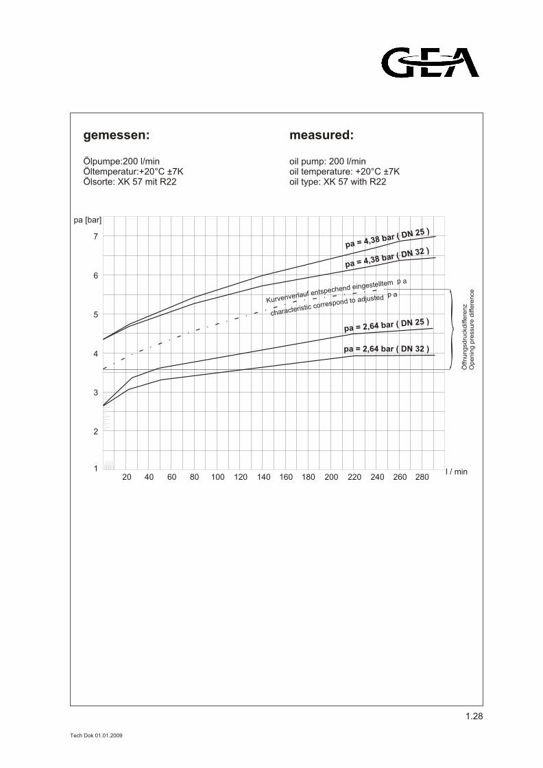
gemessen:
Ölpumpe:200 l/minÖltemperatur:+20°C ±7KÖlsorte: XK 57 mit R22
measured:
oil pump: 200 l/minoil temperature: +20°C ±7Koil type: XK 57 with R22
1
2
3
4
5
6
7
20 40 60 80 100 120 140 160 180 200 220 240 260 280l / min
pa [bar]
Öffn
un
gsd
ruck
diff
ere
nz
Op
en
ing
pre
ssu
re d
iffe
ren
ce
p ametllteseginednehcepstnefularevnev ruKp atedsjudaotdnopserroccitsiretcarahc
pa = 2,64 bar ( DN 32 )
pa = 2,64 bar ( DN 25 )
pa = 4,38 bar ( DN 25 )
pa = 4,38 bar ( DN 32 )
1.28
Tech Dok 01.01.2009
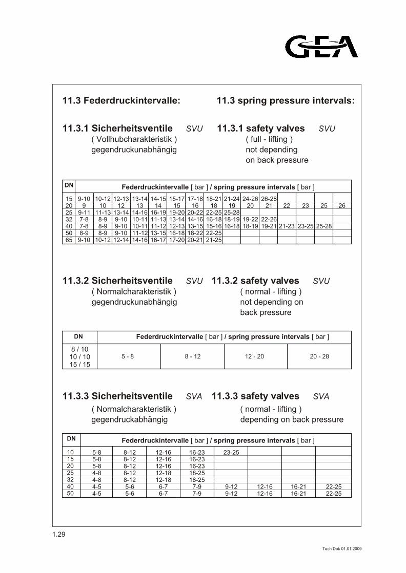
11.3 Federdruckintervalle: 11.3 spring pressure intervals:
gegendruckunabhängig
( Vollhubcharakteristik )
11.3.1 Sicherheitsventile SVU
on back pressure
not depending
( full - lifting )
11.3.1 safety valves SVU
DN
15202532405065
9-109
9-117-87-88-9
9-10
12-1312
13-149-109-109-10
12-14
13-1413
14-1610-1110-1111-1214-16
14-1514
16-1911-1311-1213-1516-17
15-1715
19-2013-1412-1316-1817-20
17-1816
20-2214-1613-1518-2220-21
18-2118
22-2516-1815-1622-2521-25
21-2419
25-2818-1916-18
26-2821
22-2619-21
24-2620
19-2218-19
22
21-23
10-1210
11-138-98-98-9
10-12
23
23-25
25
25-28
26
Federdruckintervalle [ bar ] / spring pressure intervals [ bar ]
gegendruckunabhängig
( Normalcharakteristik )
11.3.2 Sicherheitsventile SVU
back pressure
not depending on
( normal - lifting )
11.3.2 safety valves SVU
DN
5 - 8 8 - 12 12 - 20 20 - 28
Federdruckintervalle [ bar ] / spring pressure intervals [ bar ]
8 / 1010 / 1015 / 15
gegendruckabhängig
11.3.3 Sicherheitsventile SVA
depending on back pressure
11.3.3 safety valves SVA
DN
10152025324050
5-85-85-84-84-84-54-5
12-1612-1612-1612-1812-18
6-76-7
16-2316-2316-2318-2518-25
7-97-9
23-25
9-129-12
12-1612-16
16-2116-21
22-2522-25
8-128-128-128-128-125-65-6
Federdruckintervalle [ bar ] / spring pressure intervals [ bar ]
( Normalcharakteristik ) ( normal - lifting )
1.29
Tech Dok 01.01.2009
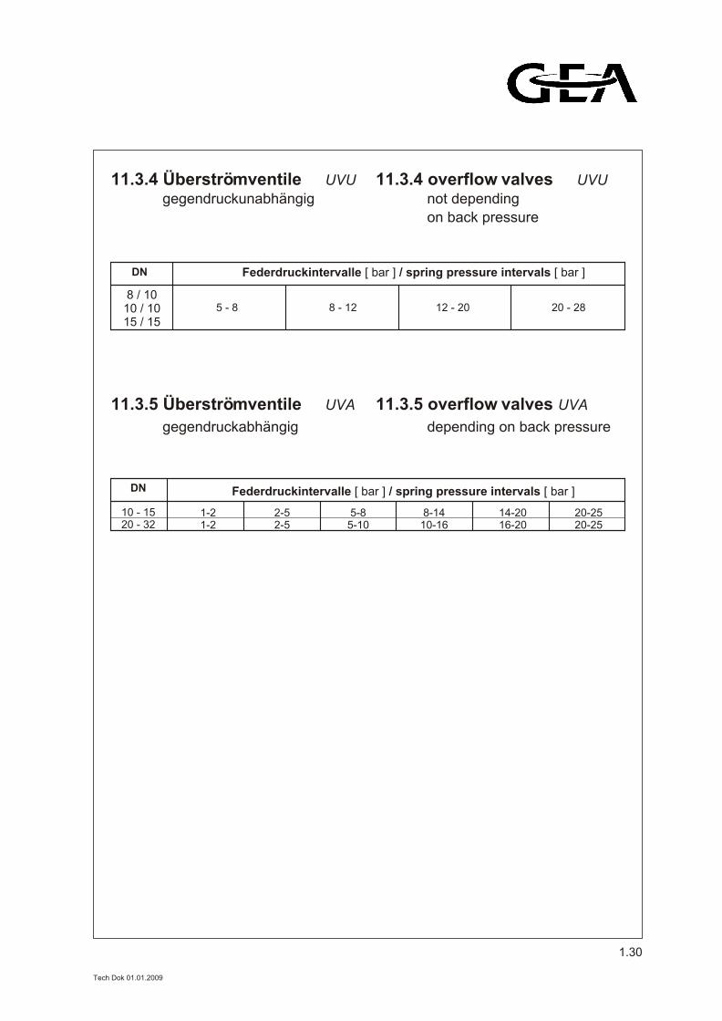
gegendruckabhängig
11.3.5 Überströmventile UVA
depending on back pressure
11.3.5 overflow valves UVA
gegendruckunabhängig
11.3.4 Überströmventile UVU
on back pressure
not depending
11.3.4 overflow valves UVU
DN
5 - 8 8 - 12 12 - 20 20 - 28
Federdruckintervalle [ bar ] / spring pressure intervals [ bar ]
8 / 1010 / 1015 / 15
DN
10 - 1520 - 32
1-21-2
5-85-10
8-1410-16
14-2016-20
20-2520-25
2-52-5
Federdruckintervalle [ bar ] / spring pressure intervals [ bar ]
1.30
Tech Dok 01.01.2009
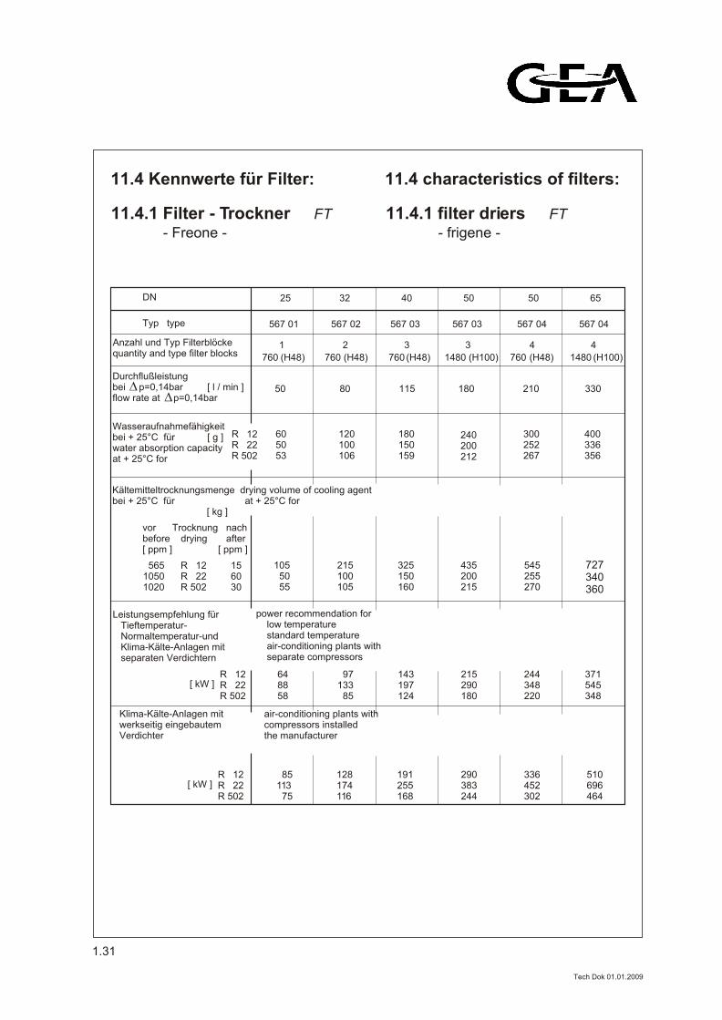
11.4 Kennwerte für Filter: 11.4 characteristics of filters:
- Freone -
11.4.1 Filter - Trockner FT
- frigene -
11.4.1 filter driers FT
25 32 40 50 50 65DN
Typ type
R 12R 22 R 502
R 12R 22 R 502
R 12R 22 R 502
565 R 12 151050 R 22 601020 R 502 30
567 01 567 02 567 03 567 03 567 04 567 04
Anzahl und Typ Filterblöckequantity and type filter blocks
Wasseraufnahmefähigkeitbei + 25°C für [ g ]water absorption capacityat + 25°C for
Kältemitteltrocknungsmenge drying volume of cooling agentbei + 25°C für at + 25°C for [ kg ]
Durchflußleistung bei p=0,14bar [ l / min ]flow rate at p=0,14bar
(H100)1480
4
(H48) 760
4
(H100) 1480 (H48) 760 (H48) 760 (H48)
1
50 80 115 180 210 330
605053
120100106
180150159
240200212
300252267
400336356
vor Trocknung nachbefore drying after[ ppm ] [ ppm ]
105 50 55
215100105
325150160
435200215
545255270
727340360
Leistungsempfehlung für Tieftemperatur- Normaltemperatur-und Klima-Kälte-Anlagen mit separaten Verdichtern
[ kW ]
[ kW ]
Klima-Kälte-Anlagen mitwerkseitig eingebautemVerdichter
power recommendation for low temperature standard temperature air-conditioning plants with separate compressors
air-conditioning plants with compressors installed the manufacturer
648858
97133 85
143197124
215290180
244348220
371545348
85113 75
128174116
191255168
290383244
336452302
510696464
760
2 3 3
1.31
Tech Dok 01.01.2009
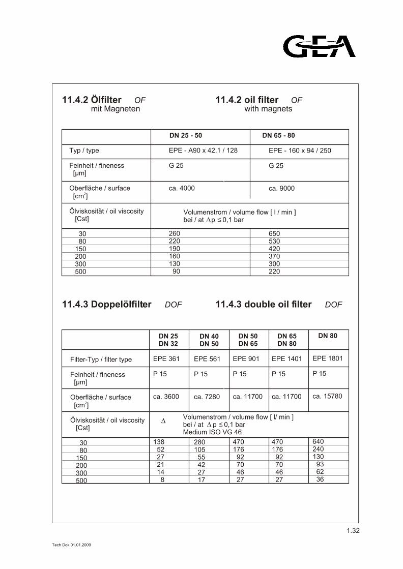
Typ / type Feinheit / fineness [µm] Oberfläche / surface
2 [cm ] Ölviskosität / oil viscosity [Cst] 30 80 150 200 300 500
EPE - A90 x 42,1 / 128 G 25 ca. 4000
260220190160130 90
EPE - 160 x 94 / 250 G 25 ca. 9000
650530420370300220
DN 25 - 50 DN 65 - 80
mit Magneten11.4.2 Ölfilter OF
with magnets11.4.2 oil filter OF
Volumenstrom / volume flow [ l / min ]bei / at p 0,1 bar
11.4.3 Doppelölfilter DOF 11.4.3 double oil filter DOF
Volumenstrom / volume flow [ l/ min ]bei / at p 0,1 barMedium ISO VG 46
Filter-Typ / filter type Feinheit / fineness [µm] Oberfläche / surface
2 [cm ] Ölviskosität / oil viscosity [Cst] 30 80 150 200 300 500
DN 25 DN 32
EPE 361
P 15 ca. 3600
138 52 27 21 14 8
DN 40 DN 50
EPE 561
P 15 ca. 7280 280105 55 42 27 17
DN 50 DN 65
EPE 901
P 15 ca. 11700 470176 92 70 46 27
DN 65 DN 80
EPE 1401
P 15 ca. 11700 470176 92 70 46 27
DN 80
EPE 1801
P 15 ca. 15780 640240130 93 62 36
1.32
D
Tech Dok 01.01.2009
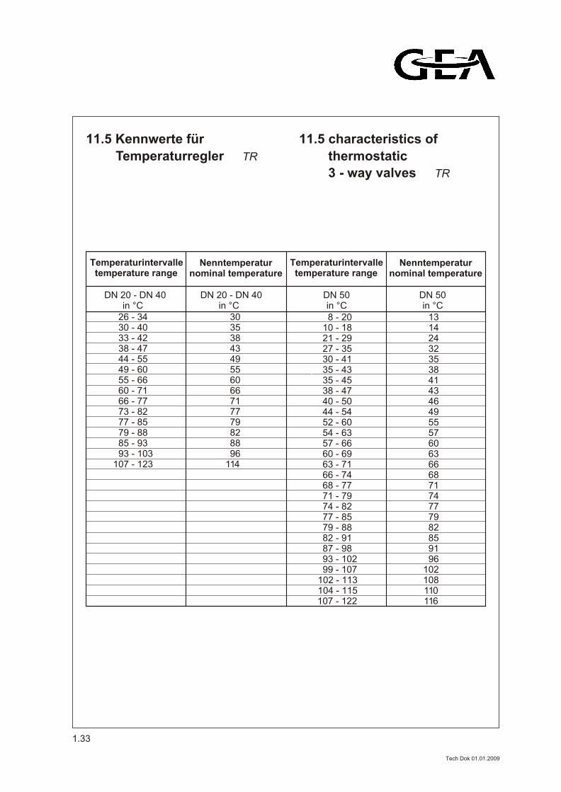
Temperaturregler TR
11.5 Kennwerte für
3 - way valves TR
thermostatic
11.5 characteristics of
Temperaturintervalletemperature range
8 - 2010 - 1821 - 2927 - 3530 - 4135 - 4335 - 4538 - 4740 - 5044 - 5452 - 6054 - 6357 - 6660 - 6963 - 7166 - 7468 - 7771 - 7974 - 8277 - 8579 - 8882 - 9187 - 98
93 - 102 99 - 107102 - 113104 - 115107 - 122
DN 20 - DN 40 DN 50 in °C in °C
26 - 3430 - 4033 - 4238 - 4744 - 5549 - 6055 - 6660 - 7166 - 7773 - 8277 - 8579 - 8885 - 93
93 - 103107 - 123
Temperaturintervalletemperature range
DN 20 - DN 40 DN 50 in °C in °C
Nenntemperaturnominal temperature
Nenntemperaturnominal temperature
3035384349556066717779828896
114
131424323538414346495557606366687174777982859196
102108110116
1.33
Tech Dok 01.01.2009
12. Schweißhinweise: 12. welding recommendations:
1. Allgemeines
Zur Gewährleistung des sicheren Durchschweißens werden AWP - Ventile an den Anschlußstutzen für das einseitige Schweißen von Stumpfstößen miteiner Schweißnahtvorbereitung entsprechend DIN 2559 Kennzahl 21 / 27 versehen.
Die zu schweißenden Werkstoffe sind grundsätzlich von Öl, Fett, Rost, Zunder und korrosionsschützenden Beschichtungenim Schweißnahtbereich zu säubern.
Eine Demontage der AWP - Ventile vor demSchweißen wird nicht empfohlen.
Bei Autogenschweißung oder Hartlötung darf die Flamme das Ventil nicht berühren,sonst demontieren.
Beim Einschweißen ist darauf zu achten,daß die Ventile frei von Achskräften, Biege- und Torsionsmomenten sindund nicht als Fixpunkte von Rohrleitungendienen.
Das Ventil muß beim Einschweißengeöffnet sein.
2. Schweißverfahren
Die Auswahl der Schweißverfahren ist abhängig von den örtlichen Begebenheiten,Möglichkeiten und vorhandenen Zulassungennach EN 288.
Grundsätzlich sind anwendbar: 1. Lichtbogenhandschweißen ( E ) 2. Gasschweißen ( G ) 3. Schutzgasschweißen MAG / MAGM / WIG
1. instructions
Dismantling
Valves:No axial forces, bending or torsional momentsshould act upon the valves.Must not be used as fixing points for pipes.
The valve has to be open during welding.
For high quality single sided butt weldingthe ends of AWP - valves have to preparedwith welding seam according DIN 2559 code 21 / 27.
In principle welded material has to be freeof oil, grease, cinder and corrosive protected coating at the range of welding seam.
Disassembly of AWP - valve is not to be recommended.
In case of gas welding or brazing, the flamemay not reach the valve, otherwise please
.
2. welding processes
The selection of welding process is depended on local conditiones and existing approvals according EN 288.
In principle can be use: 1. Manual arc welding 2. Gas welding 3. inert gas-shielded welding MAG / MAGM / WIG
1.34
Tech Dok 01.01.2009
3. Zusatzwerkstoffe
Für die richtige Auswahl der Zusatzwerkstoffeist die Schweißaufsicht vor Ort verantwortlich.Die Schweißaufsicht ( nach EN 719 ) entscheidet entsprechend der vorliegenden Werkstoffpaarung und nötigen Zulassungen über die zu verwendenen Zusatzwerkstoffe.
Die Werkstoffbezeichnungen befinden sichan AWP - Ventilen auf dem Typenschild bzw.in Form von Hartsignierung im Gehäusekörper, in der Hersteller-bescheinigung ( Werkstoffliste ) oder in der Auftragsbestätigung.
3. additional materials
The local welding surveyance is reponsible for the correct choice of additional material. The welding surveyance ( acc. to EN 719 ) decides about additional materials according to existing material combinations and necessary permittances. The material code can be foundon the AWP-nameplate,as a kind of stamp on valve bodyin type - test approvalor on the order confirmation.
1.35
Tech Dok 01.01.2009
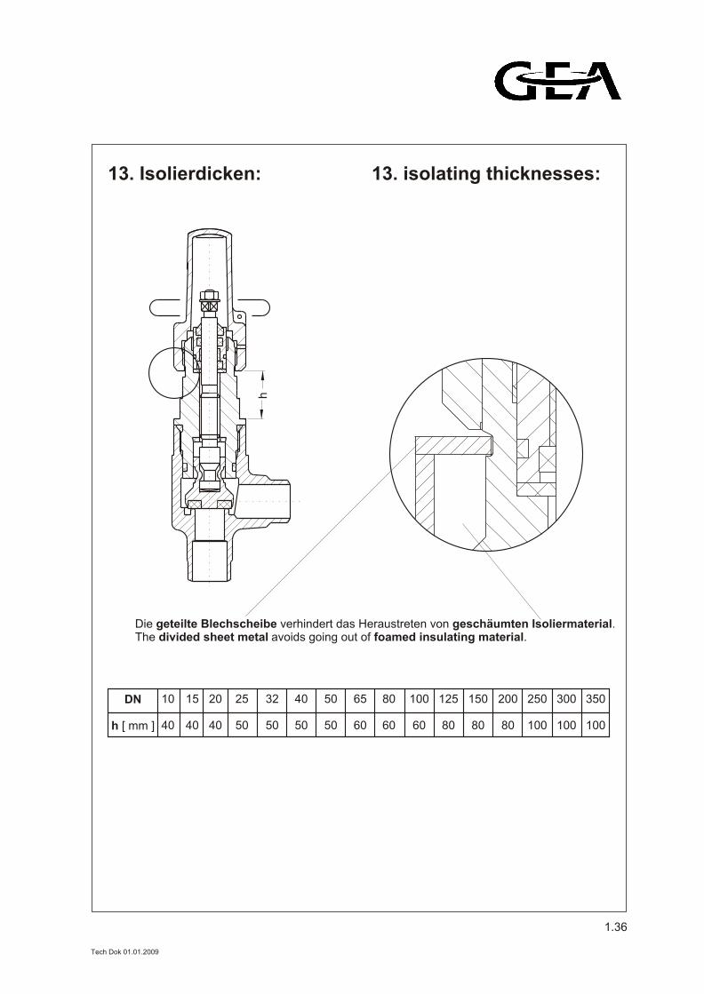
13. Isolierdicken: 13. isolating thicknesses:
Die geteilte Blechscheibe verhindert das Heraustreten von geschäumten Isoliermaterial.The divided sheet metal avoids going out of foamed insulating material.
DN
h [ mm ]
15
40
10
40
20
40
25
50
32
50
40
50
50
50
65
60
80
60
100
60
125
80
150
80
200
80
250
100
300
100
350
100
h
1.36
Tech Dok 01.01.2009
CE(Kennzeichen der Konformitätmit Richtlinie 97/23/EG,Druckgeräterichtlinie)
TÜVGermanischer LloydLloyd´s RegisterDet Norske VeritasBureau VeritasClass NKSAQRSUDTGostgortechnadzor Russia
Weitere auf Anfrage!
14. Zulassungen, Zertifikate
14. approvals, certificates
CE(mark of conformity accordingcode 97/23/EG,pressure devices)
TÜVGermanischer LloydLloyd´s RegisterDet Norske VeritasBureau VeritasClass NKSAQRSUDTGostgortechnadzor Russia
Further upon request!
1.37
Tech Dok 01.01.2009