Embed Size (px)
Citation preview

1
Pipeline Current MapperPCM+
Radiodetection PCM

2
The PCM can….
• Find contacts with other structures
• Evaluate Pipe Coating for defects
• Perform periodic Pipeline surveys
• Find defective Insulation joints
Radiodetection PCM

3
What is different about PCM• High output power Transmitter
• Low Frequency signal
• Current Direction of applied signal
• Data logging of current measurements
• A Frame pinpointing of coating holidays
Radiodetection PCM

4
Benefits of low frequency
Radiodetection PCM
testpoint
AC Tx
signalstrength(dBmA)
distance
DC
4Hz
1KHz

5
Benefits of low frequency
Radiodetection PCM
1A (1KHz)
400mA
600m
A200mA
400m
A
1A (4Hz)
40mA
960m
A900mA
60m
Afault

6
The Transmitter utilises..
• High output power (150W)
• Very low frequency
• This helps to…. increase range reduce coupling to other
services reduce field distortion
Radiodetection PCM

7
The Transmitter
• Can be powered from… 110/240Vac The D.C output of a
rectifier (20 to 50vD.C) External Automotive
batteries (24v to 48V)
Radiodetection PCM
8
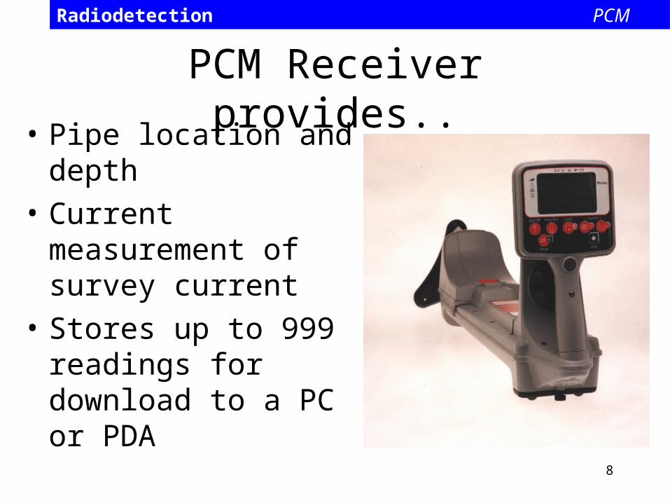
PCM Receiver provides..• Pipe location and
depth
• Current measurement of survey current
• Stores up to 999 readings for download to a PC or PDA
Radiodetection PCM

9
Transmitter connection• Typical rectifier
installation.
• Provides a perfect pipe connection point
• Anode provides perfect ground connection point
Radiodetection PCM

10
Transmitter Connection
• Disconnect the rectifier output from both pipe and Anode
• Connect the PCM transmitter in place of the rectifier
Radiodetection PCM

11
Setting the Transmitter
• Three output settings
4Hz and 98Hz
4Hz, 8Hz and 98Hz
4Hz, 8Hz and 512Hz
Radiodetection PCM

12
Setting the Transmitter
• Set Current switch to desired current
• The PCM transmitter is a constant current source, this ensures stable survey readings.
Radiodetection PCM

13
Taking current reading
• Ensure both PCM receiver is set to the same frequency as the Transmitter
• Pinpoint the pipe in the peak Mode
Radiodetection PCM
100%95%

14
Taking Current Readings• Hold the Receiver
Steady on the ground, press and hold the PCM Key.
• Current is displayed after approximately 3 seconds
Radiodetection PCM

15
PCM current v Line Drops
Radiodetection PCM
12
34
56
78
910
LOCATION Nr
000001111
AMPS
LINEAR COMPARISONS
Data obtained during comparative tests on site

16
Current Direction• This tells you in which direction the
Current is flowing – Aids fault analysis
Radiodetection PCM
Transmitter
short
target line

17
Datalogging
• 999 readings can be stored• Stored readings can be
reviewed on PCM+ or downloaded to PC
• Downloaded files are in text format and can be displayed using Excel or 123 speadsheets
Radiodetection PCM
18
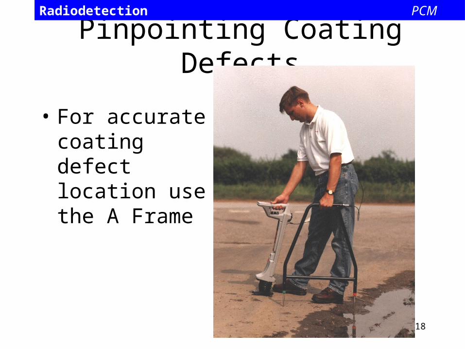
Pinpointing Coating Defects
• For accurate coating defect location use the A Frame
Radiodetection PCM

19
Finding Coating Defects
Radiodetection PCM
TransmitterA-Frame

20
Case Histories
Radiodetection PCM

21
Radiodetection PCM

22
Defects found by PCMCut away ready for repair
Radiodetection PCM

23
Close up view of cutaway showing area of metal loss
Radiodetection PCM

24
Cables in contact with pipe
Radiodetection PCM
25
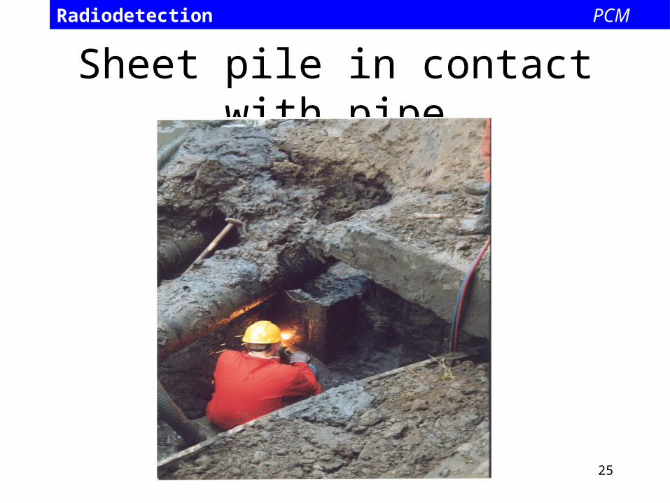
Sheet pile in contact with pipe
Radiodetection PCM

26
Current Attenuation GraphActual PCM Results
3 steps are different looking in mA but nearly identical in dB

AC Voltage Gradient• Can be part of Current tools• Becoming very popular• Extreme sensitivity• Rejection of interference• Very accurate location of faults
– typically better then 6"
• Sometimes part of Current Attenuation equipment• This method deserves to be considered as a solid
tool for integrity and the ECDA process.

ACVG in Operation• Both signal
strength and direction arrows lead user to holiday.
• Fault value is proportional to holiday size and
soil resistivity.

Pool of PotentialIs AC, but at any instant in time, there is a direction.Is AC, but at any instant in time, there is a direction.

ACVG Receiver Theory

ACVG Tuning
• Older systems used a simple DMM– Does not tune to any one frequency– 60 Hz, cable earth faults, telecom noise Rx’d
• Very tight tuning in the signal generator and receiver effectively increases sensitivity as it ignores current from other sources– SNR improves

• In this case the next fault was quite close (20-30m) which is why the left side of graph climbs quickly.
• Other cases may show 100s of meters of signal at 30 and under..

Dig Pictures