Embed Size (px)
Citation preview
Modelling of a novel in-pipe microrobot design withIPMC legsM Vahabi*, E Mehdizadeh, M Kabganian, and F Barazandeh
Department of Mechanical Engineering, Amirkabir University of Technology, Tehran, Iran
The manuscript was received on 13 March 2010 and was accepted after revision for publication on 23 June 2010.
DOI: 10.1243/09596518JSCE1042
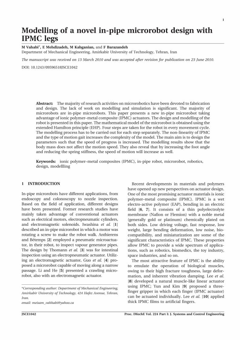
Abstract: The majority of research activities on microrobotics have been devoted to fabricationand design. The lack of work on modelling and simulation is significant. The majority ofmicrorobots are in-pipe microrobots. This paper presents a new in-pipe microrobot takingadvantage of ionic polymer–metal composite (IPMC) actuators. The design and modelling of therobot is presented in this paper. The mathematical model of the microrobot is obtained using theextended Hamilton principle (EHP). Four steps are taken for the robot in every movement cycle.The modelling process has to be carried out for each step separately. The non-linearity of IPMCand the type of motion gait increases the complexity of the model. The main aim is to design theparameters such that the speed of progress is increased. The modelling results show that thebody mass does not affect the motion speed. They also reveal that by increasing the foot angleand reducing the spring stiffness, the speed of motion will increase as well.
Keywords: ionic polymer–metal composites (IPMC), in-pipe robot, microrobot, robotics,design, modellling
1 INTRODUCTION
In-pipe microrobots have different applications, from
endoscopy and colonoscopy to nozzle inspection.
Based on the field of application, different designs
have been presented. Former research studies have
mainly taken advantage of conventional actuators
such as electrical motors, electropneumatic cylinders,
and electromagnetic solenoids. Iwashina et al. [1]
described an in-pipe microrobot in which a motor was
rotating a screw to make the robot walk. Anthierens
and Betemps [2] employed a pneumatic microactua-
tor, in their robot, to inspect vapour generator pipes.
The design by Thomann et al. [3] was for intestinal
inspection using an electropneumatic actuator. Utiliz-
ing an electromagnetic actuator, Guo et al. [4] pro-
posed a microrobot capable of moving along a narrow
passage. Li and He [5] presented a crawling micro-
robot, also with an electromagnetic actuator.
Recent developments in materials and polymers
have opened up new perspectives on actuator design.
One of the most promising actuator materials is ionic
polymer–metal composite (IPMC). IPMC is a wet
electro-active polymer (EAP), bending in an electric
field [6, 7]. It consists of a thin polyelectrolyte
membrane (Nafion or Flemion) with a noble metal
(generally gold or platinum) chemically plated on
both sides. Low driving voltage, fast response, low
weight, large bending deformation, low noise, bio-
compatibility, and miniaturization are some of the
significant characteristics of IPMC. These properties
allow IPMC to provide a wide spectrum of applica-
tions, such as robotics, biomedics, the toy industry,
space industries, and so on.
The most attractive feature of IPMC is the ability
to emulate the operation of biological muscles,
owing to their high fracture toughness, large defor-
mation, and inherent vibration damping. Lee et al.
[8] developed a natural muscle-like linear actuator
using IPMC; Yun and Kim [9] proposed a three-
finger gripper in which each finger (IPMC actuator)
can be actuated individually. Lee et al. [10] applied
thick IPMC films to artificial fingers.
*Corresponding author: Department of Mechanical Engineering,
Amirkabir University of Technology, 424 Hafez Avenue, Tehran,
Iran.
email: [email protected]
1
JSCE1042 Proc. IMechE Vol. 224 Part I: J. Systems and Control Engineering
In the context of walking robots, Tadokoro et al. [11]
presented an actuation device using one pair of IPMCs
called elliptic friction drive (EFD) actuator elements.
This element generates an elliptic motion as used in
ultrasonic motors to drive objects by friction. Kim et al.
[12] constructed a ciliary based eight-legged micro-
robot with cast film-based IPMC actuators, operating
in aqueous surroundings (as inside the human body).
Guo et al. [13] developed a new multi-degrees-of-
freedom (DOF) underwater microrobot with eight
IPMC actuators as legs and IPMC sensors as the
sensing device. Ye et al. [14] presented a crab-like
underwater microrobot with eight legs. Each leg was
made up of two pieces of IPMC.
None of the above research studies was directed to-
wards moving in narrow passages using IPMC actuators.
In self-contained systems, the capacity of batteries is
limited. Energy efficiency becomes important to prolong
the operating period. IPMC truly satisfies low energy
consumption because of its characteristics [15].
In the current paper the aim is to design and model
an autonomous in-pipe microrobot capable of mov-
ing in narrow confined areas. IPMC actuators are
hired for the legs. The microrobot can move slowly; in
pipes. First, the conceptual design of the microrobot
is carried out and the motion sequence is illustrated
comprehensively. Next, the equations of motion for
the proposed microrobot are derived using the
extended Hamilton principle (EHP). Then, the nu-
merical analysis results for the microrobot movement
are presented in terms of different voltage inputs.
Finally, the effect of various parameters such as body
mass, foot angle, and so on, on the movement of the
microrobot is examined.
2 CONCEPTUAL DESIGN OF IN-PIPEMICROROBOT
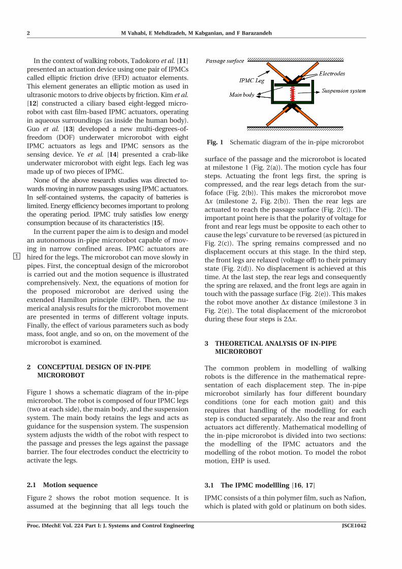
Figure 1 shows a schematic diagram of the in-pipe
microrobot. The robot is composed of four IPMC legs
(two at each side), the main body, and the suspension
system. The main body retains the legs and acts as
guidance for the suspension system. The suspension
system adjusts the width of the robot with respect to
the passage and presses the legs against the passage
barrier. The four electrodes conduct the electricity to
activate the legs.
2.1 Motion sequence
Figure 2 shows the robot motion sequence. It is
assumed at the beginning that all legs touch the
surface of the passage and the microrobot is located
at milestone 1 (Fig. 2(a)). The motion cycle has four
steps. Actuating the front legs first, the spring is
compressed, and the rear legs detach from the sur-
foface (Fig. 2(b)). This makes the microrobot move
Dx (milestone 2, Fig. 2(b)). Then the rear legs are
actuated to reach the passage surface (Fig. 2(c)). The
important point here is that the polarity of voltage for
front and rear legs must be opposite to each other to
cause the legs’ curvature to be reversed (as pictured in
Fig. 2(c)). The spring remains compressed and no
displacement occurs at this stage. In the third step,
the front legs are relaxed (voltage off) to their primary
state (Fig. 2(d)). No displacement is achieved at this
time. At the last step, the rear legs and consequently
the spring are relaxed, and the front legs are again in
touch with the passage surface (Fig. 2(e)). This makes
the robot move another Dx distance (milestone 3 in
Fig. 2(e)). The total displacement of the microrobot
during these four steps is 2Dx.
3 THEORETICAL ANALYSIS OF IN-PIPEMICROROBOT
The common problem in modelling of walking
robots is the difference in the mathematical repre-
sentation of each displacement step. The in-pipe
microrobot similarly has four different boundary
conditions (one for each motion gait) and this
requires that handling of the modelling for each
step is conducted separately. Also the rear and front
actuators act differently. Mathematical modelling of
the in-pipe microrobot is divided into two sections:
the modelling of the IPMC actuators and the
modelling of the robot motion. To model the robot
motion, EHP is used.
3.1 The IPMC modellling [16, 17]
IPMC consists of a thin polymer film, such as Nafion,
which is plated with gold or platinum on both sides.
Fig. 1 Schematic diagram of the in-pipe microrobot
2 M Vahabi, E Mehdizadeh, M Kabganian, and F Barazandeh
Proc. IMechE Vol. 224 Part I: J. Systems and Control Engineering JSCE1042
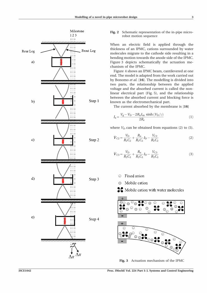
When an electric field is applied through the
thickness of an IPMC, cations surrounded by water
molecules migrate to the cathode side resulting in a
bending motion towards the anode side of the IPMC.
Figure 3 depicts schematically the actuation me-
chanism of the IPMC.
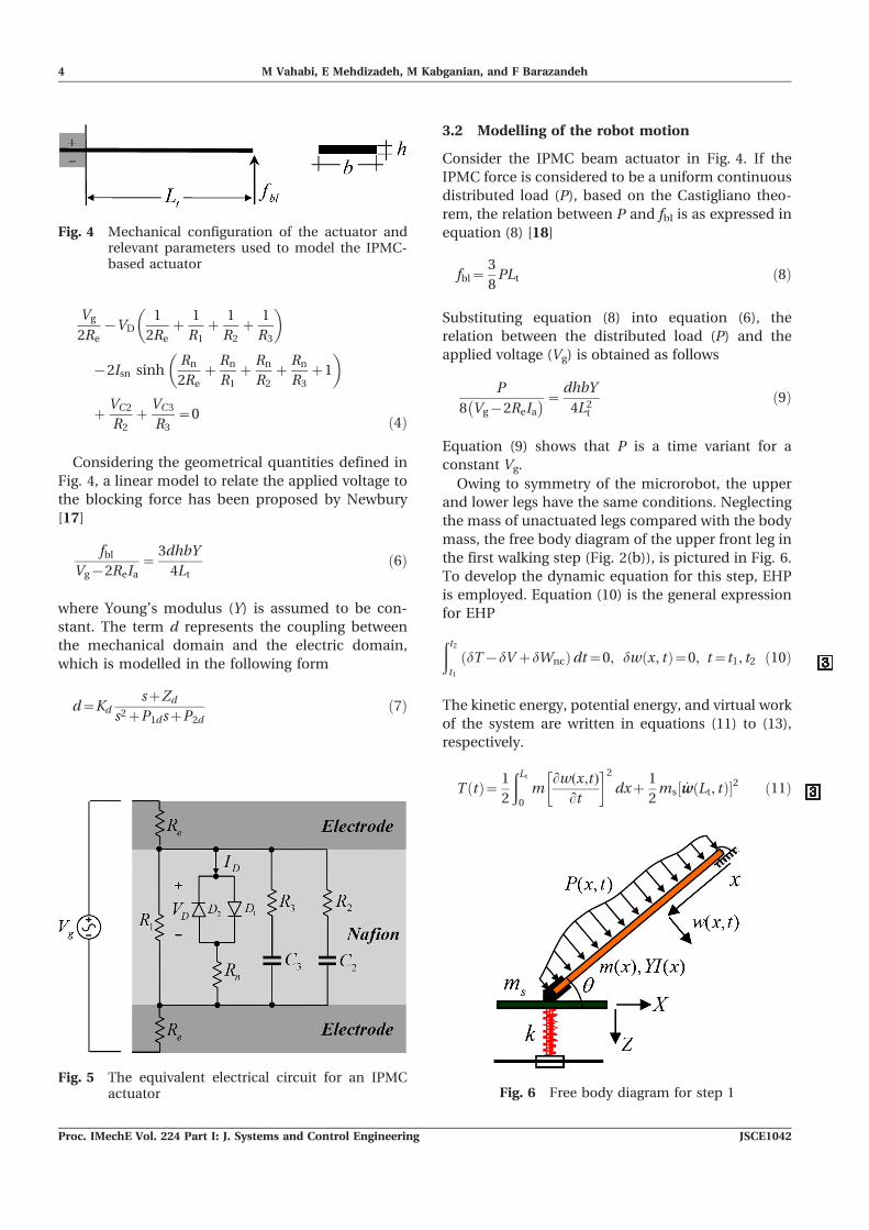
Figure 4 shows an IPMC beam, cantilevered at one
end. The model is adapted from the work carried out
by Bonomo et al. [16]. The modelling is divided into
two parts, the relationship between the applied
voltage and the absorbed current is called the non-
linear electrical part (Fig. 5), and the relationship
between the absorbed current and blocking force is
known as the electromechanical part.
The current absorbed by the membrane is [16]
Ia~Vg{VD{2RnIsn sinh VD=cð Þ
2Reð1Þ
where VD can be obtained from equations (2) to (5).
_VV C2~VD
R2C2z
Rn
R2C2ID{
VC2
R2C2ð2Þ
_VV C3~VD
R3C3z
Rn
R3C3ID{
VC3
R3C3ð3Þ
Fig. 2 Schematic representation of the in-pipe micro-robot motion sequence
Fig. 3 Actuation mechanism of the IPMC
Modelling of a novel in-pipe microrobot design 3
JSCE1042 Proc. IMechE Vol. 224 Part I: J. Systems and Control Engineering
Vg
2Re{VD
1
2Rez
1
R1z
1
R2z
1
R3
� �
{2Isn sinhRn
2Rez
Rn
R1z
Rn
R2z
Rn
R3z1
� �
zVC2
R2z
VC3
R3~0 ð4Þ
Considering the geometrical quantities defined in
Fig. 4, a linear model to relate the applied voltage to
the blocking force has been proposed by Newbury
[17]
fbl
Vg{2ReIa~
3dhbY
4Ltð6Þ
where Young’s modulus (Y) is assumed to be con-
stant. The term d represents the coupling between
the mechanical domain and the electric domain,
which is modelled in the following form
d~KdszZd
s2zP1dszP2dð7Þ
3.2 Modelling of the robot motion
Consider the IPMC beam actuator in Fig. 4. If the
IPMC force is considered to be a uniform continuous
distributed load (P), based on the Castigliano theo-
rem, the relation between P and fbl is as expressed in
equation (8) [18]
fbl~3
8PLt ð8Þ
Substituting equation (8) into equation (6), the
relation between the distributed load (P) and the
applied voltage (Vg) is obtained as follows
P
8 Vg{2ReIa
� �~dhbY
4L2t
ð9Þ
Equation (9) shows that P is a time variant for a
constant Vg.
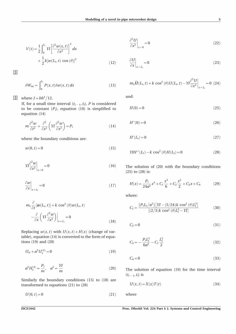
Owing to symmetry of the microrobot, the upper
and lower legs have the same conditions. Neglecting
the mass of unactuated legs compared with the body
mass, the free body diagram of the upper front leg in
the first walking step (Fig. 2(b)), is pictured in Fig. 6.
To develop the dynamic equation for this step, =EHP
is employed. Equation (10) is the general expression
for EHP
ðt2
t1
dT{dV zdWncð Þdt~0, dw x, tð Þ~0, t~t1, t2 ð10Þ
The kinetic energy, potential energy, and virtual work
of the system are written in equations (11) to (13),
respectively.
T tð Þ~ 1
2
ðLt
0
mLw(x,t)
Lt
� �2
dxz1
2ms _ww Lt, tð Þ½ �2 ð11Þ
Fig. 6 Free body diagram for step 1
Fig. 4 Mechanical configuration of the actuator andrelevant parameters used to model the IPMC-based actuator
Fig. 5 The equivalent electrical circuit for an IPMCactuator
===========================================================
===========================================================
4 M Vahabi, E Mehdizadeh, M Kabganian, and F Barazandeh
Proc. IMechE Vol. 224 Part I: J. Systems and Control Engineering JSCE1042
=
V tð Þ~ 1
2
ðLt
0
YIL2w x, tð Þ
Lx2
� �2
dx
z1
2k w Lt, tð Þ cos hð Þ½ �2 ð12Þ
=
dWnc~
ðLt
0
P x, tð Þdw x, tð Þdx ð13Þ
= where I~bh3�
12.
If, for a small time interval (ti 2 1, ti), P is considered
to be constant (Pi), equation (10) is simplified to
equation (14)
mL2w
Lt2z
L2
Lx2YI
L2w
Lx2
� �~Pi ð14Þ
where the boundary conditions are:
w 0, tð Þ~0 ð15Þ
YIL2w
Lx2
x~0
~0 ð16Þ
Lw
Lx
x~Lt
~0 ð17Þ
msLLt
_ww Lt, tð Þ½ �zk cos2 hð Þw Lt, tð Þ
{LLx
YIL2w
Lx2
� �x~Lt
~0ð18Þ
Replacing w x, tð Þ with U x, tð ÞzH xð Þ (change of var-
iable), equation (14) is converted to the form of equa-
tions (19) and (20)
Uttza2U 4ð Þx ~0 ð19Þ
a2H 4ð Þx ~
Pi
m, a2~
YI
mð20Þ
Similarly the boundary conditions (15) to (18) are
transformed to equations (21) to (28)
U 0, tð Þ~0 ð21Þ
L2U
Lx2
x~0
~0 ð22Þ
LU
Lx
x~Lt
~0 ð23Þ
ms€UU Lt, tð Þzk cos2 hð ÞU Lt, tð Þ{YI
L3U
Lx3
x~Lt
~0 ð24Þ
and:
H 0ð Þ~0 ð25Þ
H ’’ 0ð Þ~0 ð26Þ
H ’ Ltð Þ~0 ð27Þ
YIH ’’’ Ltð Þ{k cos2 hð ÞH Ltð Þ~0 ð28Þ
The solution of (20) with the boundary conditions
(25) to (28) is:
H xð Þ~ Pi
24a2x4zC1
x3
6zC2
x2
2zC3xzC4 ð29Þ
where:
C1~PiLt
�a2
� �YI{ 5=24ð Þk cos2 hð ÞL3
t
�2=3ð Þk cos2 hð ÞL3
t {YI½ � ð30Þ
C2~0 ð31Þ
C3~{PiL
3t
6a2{C1
L2t
2ð32Þ
C4~0 ð33Þ
The solution of equation (19) for the time interval
(ti 2 1, ti) is
U x, tð Þ~X xð ÞT tð Þ ð34Þ
where
Modelling of a novel in-pipe microrobot design 5
JSCE1042 Proc. IMechE Vol. 224 Part I: J. Systems and Control Engineering
X xð Þ~ sinh lxð ÞzB cosh lxð Þ
zC sin lxð ÞzD cos lxð Þ ð35Þ
T tð Þ~E sin al2t� �
zF cos al2t� �
ð36Þ
Replacing equation (34) in the boundary conditions
(21) to (24), the constants B, C, D, and l are obtained
as follows
B~D~0 ð37Þ
C~{cosh lLtð Þcos lLtð Þ ð38Þ
msa2l4{k cos2 hð Þ �
sinh lLtð Þ{ cosh lLtð Þ tan lLtð Þ½ �
z2YIl3 cosh lLtð Þ~0 ð39Þ
Considering the continuity of displacement U x, tið Þ~ð{H xð Þzw x, ti{1ð ÞÞ and setting the end condition of
the former time interval for the next sequence, the
following equations are derived by substituting equa-
tions (35) and (36) into equation (34)
al2X xð ÞE~ _ww x, ti{1ð Þ ð40Þ
X xð ÞF~{H xð Þzw x, ti{1ð Þ ð41Þ
Multiplying the equations (40) and (41) by X and
integrating (with respect to x), E and F are obtained
E~2
Ltal2
ðLt
0
_ww x, ti{1ð ÞX dx ð42Þ
Table 1 Initial and boundary conditions for different steps
Step no. Actuated leg Boundary conditions Initial conditions
Step 1(Fig. 2(b))
Front legw(0, t) 5 0,
Lw
Lx
x~Lt
~0, YIL2w
Lx2
x~0
~0,
msLLt
_ww Lt, tð Þ½ �zk cos2 hð Þw Lt, tð Þ{ LLx
YIL2w
Lx2
� �x~Lt
~0
w(x, 0) 5 0w(x, 0) 5 0
Step 2(Fig. 2(c))
Rear leg
w(0, t) 5 0,Lw
Lx
x~0
~0, YIL2w
Lx2
x~Lt
~0,
LLx
YIL2w
Lx2
� �x~Lt
~0
w(x, 0) 5 0w(x, 0) 5 0
Step 3(Fig. 2(d))
Front leg
w(0, t) 5 0,Lw
Lx
x~0
~0, YIL2w
Lx2
x~Lt
~0,
LLx
YIL2w
Lx2
� �x~Lt
~0
w(x, 0) 5 wf(x, tff)w(x, 0) 5 0
Step 4(Fig. 2(e))
Rear leg
w(0, t) 5 0,Lw
Lx
x~Lt
~0, YIL2w
Lx2
x~0
~0,
msLLt
_ww Lt, tð Þð Þzk cos2 hð Þw Lt, tð Þ{ LLx
YIL2w
Lx2
� �x~Lt
~0
w(x, 0) 5 wr(x, trr)w(x, 0) 5 0
Table 2 IPMC actuator characteristics
Parameters Re Rn R1 R2 R3 C2 C3 c Isn Y Kd Zd P1d P2d
Values 1.814 160 4196 293.8 67.6 0.06 0.01 0.3907 4.414e-5 9.9e7 2.144e-7 141.66 94.5 6 101.89
Fig. 7 The experimental set-up for identification ofthe IPMC parameters
===========================================================
6 M Vahabi, E Mehdizadeh, M Kabganian, and F Barazandeh
Proc. IMechE Vol. 224 Part I: J. Systems and Control Engineering JSCE1042
=F~
2
Lt
ðLt
0
{H xð Þzw x, ti{1ð Þ½ �X dx ð43Þ
= Likewise the modelling procedure for the other
walking steps is performed by replacing the boundary
conditions (15) to (18) with the equations listed in
Table 1. In Table 1, the subscripts f, r, ff, and fr refer to
front, rear, final condition of front legs, and final
condition of rear legs, respectively.
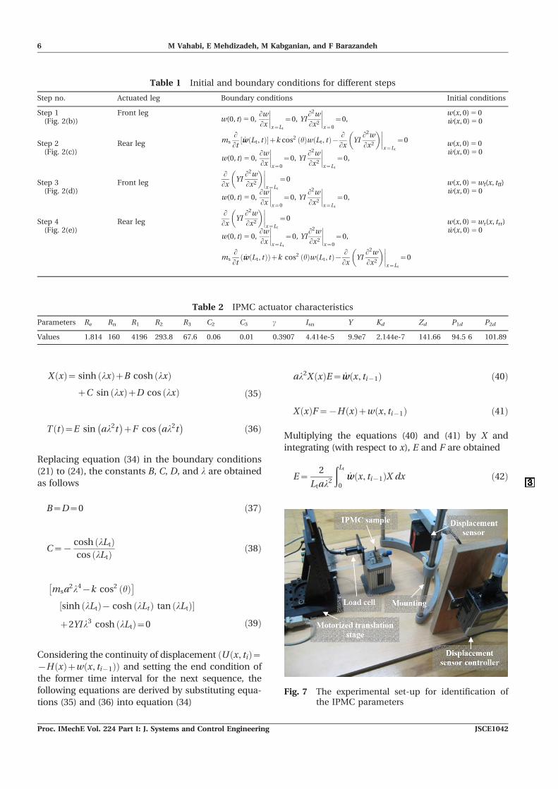
4 IDENTIFICATION OF IPMC PARAMETERS
In order to run the simulation, the IPMC parameters
must be identified. The identification is experimen-
tally performed using an incorporating non-linear
and linear least-squares method [19]. The identified
parameters are shown in Table 2. Figure 7 is the
experimental set-up for identification of IPMC para-
meters. The identification method will be explained
in another publication.
5 RESULTS AND DISCUSSION
5.1 Simulation results
After identifying the IPMC parameters, a primary
simulation run is conducted based on the values
presented in Tables 2 and 3. These values are the
same for all simulations in this paper, unless other-
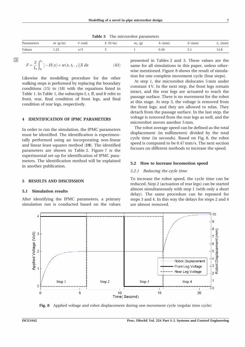
wise mentioned. Figure 8 shows the result of simula-
tion for one complete movement cycle (four steps).
At step 1, the microrobot dislocates 5 mm under
constant 4 V. In the next step, the front legs remain
intact, and the rear legs are actuated to reach the
passage surface. There is no movement for the robot
at this stage. At step 3, the voltage is removed from
the front legs; and they are allowed to relax. They
detach from the passage surface. In the last step, the
voltage is removed from the rear legs as well, and the
microrobot moves another 5 mm.
The robot average speed can be defined as the total
displacement (in millimetres) divided by the total
cycle time (in seconds). Based on Fig. 8, the robot
speed is computed to be 0.47 mm/s. The next section
focuses on different methods to increase the speed.
5.2 How to increase locomotion speed
5.2.1 Reducing the cycle time
To increase the robot speed, the cycle time can be
reduced. Step 2 (actuation of rear legs) can be started
almost simultaneously with step 1 (with only a short
delay). The same procedure can be repeated for
steps 3 and 4. In this way the delays for steps 2 and 4
are almost removed.
Table 3 The microrobot parameters
Parameters m (g/m) h (rad) k (N/m) ms (g) h (mm) b (mm) Lt (mm)
Values 1.25 p/3 5 1 0.36 5.1 14.8
Fig. 8 Applied voltage and robot displacement during one movement cycle (regular time cycle)
Modelling of a novel in-pipe microrobot design 7
JSCE1042 Proc. IMechE Vol. 224 Part I: J. Systems and Control Engineering
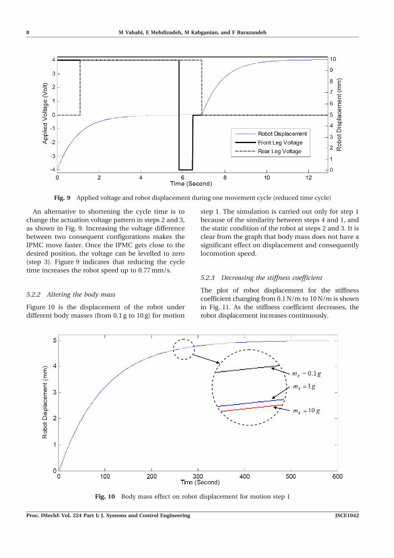
An alternative to shortening the cycle time is to
change the actuation voltage pattern in steps 2 and 3,
as shown in Fig. 9. Increasing the voltage difference
between two consequent configurations makes the
IPMC move faster. Once the IPMC gets close to the
desired position, the voltage can be levelled to zero
(step 3). Figure 9 indicates that reducing the cycle
time increases the robot speed up to 0.77 mm/s.
5.2.2 Altering the body mass
Figure 10 is the displacement of the robot under
different body masses (from 0.1 g to 10 g) for motion
step 1. The simulation is carried out only for step 1
because of the similarity between steps 4 and 1, and
the static condition of the robot at steps 2 and 3. It is
clear from the graph that body mass does not have a
significant effect on displacement and consequently
locomotion speed.
5.2.3 Decreasing the stiffness coefficient
The plot of robot displacement for the stiffness
coefficient changing from 0.1 N/m to 10 N/m is shown
in Fig. 11. As the stiffness coefficient decreases, the
robot displacement increases continuously.
Fig. 9 Applied voltage and robot displacement during one movement cycle (reduced time cycle)
Fig. 10 Body mass effect on robot displacement for motion step 1
8 M Vahabi, E Mehdizadeh, M Kabganian, and F Barazandeh
Proc. IMechE Vol. 224 Part I: J. Systems and Control Engineering JSCE1042
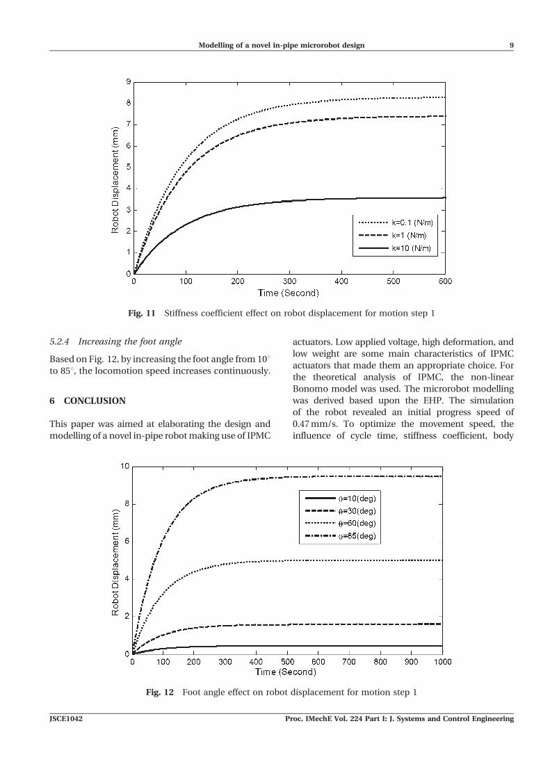
5.2.4 Increasing the foot angle
Based on Fig. 12, by increasing the foot angle from 10uto 85u, the locomotion speed increases continuously.
6 CONCLUSION
This paper was aimed at elaborating the design and
modelling of a novel in-pipe robot making use of IPMC
actuators. Low applied voltage, high deformation, and
low weight are some main characteristics of IPMC
actuators that made them an appropriate choice. For
the theoretical analysis of IPMC, the non-linear
Bonomo model was used. The microrobot modelling
was derived based upon the EHP. The simulation
of the robot revealed an initial progress speed of
0.47 mm/s. To optimize the movement speed, the
influence of cycle time, stiffness coefficient, body
Fig. 12 Foot angle effect on robot displacement for motion step 1
Fig. 11 Stiffness coefficient effect on robot displacement for motion step 1
Modelling of a novel in-pipe microrobot design 9
JSCE1042 Proc. IMechE Vol. 224 Part I: J. Systems and Control Engineering
mass, and foot angle were examined. These were
found to be able to increase the robot progress speed
up to 1.4 mm/s.
ACKNOWLEDGEMENT
The research presented in this paper is supportedby Iran National Science Foundation. The authorsgratefully acknowledge this support.
F Authors 2010
REFERENCES
1 Iwashina, S., Hayashi, I., Iwatsuki, N., andNakamura, K. Development of in-pipe operationmicrorobots. Proceedings of the 5th InternationalSymposium on Micro machine and human science,Nagoya, 2–4 October 1994, pp. 41–45.
2 Anthierens, C. and Betemps, M. Control design ofan electro pneumatic micro actuator for a mobilein-pipe micro robot. In Proceedings of the 5thFranco-Japanese Congress & 3rd European-AsianCongress, Mecatronics’01, Besancon, 9–11 October2001, pp. 360–365.
3 Thomann, G., Betemps, M., and Redarce, T. Thedesign of a new type of micro robot for theintestinal inspection. Proceedings of the IEEE/RSJInternational Conference on Intelligent robots andsystems, Switzerland, 30 September–5 October2002, pp. 1385–1390.
4 Guo, S., Pan, Q., and Khamesee, M. B. Develop-ment of a novel type of microrobot for biomedicalapplication. Microsystems Technol., 2008, 14(N3),307–314.
5 Li, C. and He, X. A bio-mimetic pipe crawlingmicrorobot driven based on self-excited vibration.Proceedings of the IEEE International Conferenceon Robotics and biomimetics, Sanya, 15–18 Decem-ber 2007, pp. 984–988.
6 Bar-Cohen, Y. Electroactive polymer (EAP) actua-tors as artificial muscles–reality, potential andchallenges, 2004 (SPIE Press, Washington).
7 Shahinpoor, M. and Kim, K. J. Ionic polymer–metal composites: I. Fundamentals. Int. J. SmartMater. Structs, 2001, 10, 819–833.
8 Lee, S., Kim, K. J., and Park, S. Modeling andexperiment of a muscle-like linear actuator usingan ionic polymer metal composite and its actua-tion characteristics. Int. J. Smart Mater. Structs,2007, 16, 583–588.
9 Yun, K. and Kim, W. J. System identification andmicroposition control of ionic polymer metalcomposite for three-finger gripper manipulation.Proc. IMechE, Part I: J. Systems and ControlEngineering, 2006, 220(7), 539–551. DOI: 10.1243/09596518JSCE215.
10 Lee, S. J., Han, M. J., Kim, S. J., Jho, J. Y., Lee, H.Y., and Kim, Y. H. A new fabrication method forIPMC actuators and application to artificial fingers.Int. J. Smart Mater. Structs, 2006, 15, 1217–1224.
11 Tadokoro, S., Murakami, T., Fuji, S., Kanno, R.,Hattori, M., and Takamori, T. An elliptic frictiondrive element using an ICPF actuator. Proceedingsof IEEE International Conference on Robotics andautomation, Minneapolis, 22–28 April 1996, pp.205–212.
12 Kim, B., Ryu, J., Jeong, Y., Tak, Y., Kim, B., andPark, J. A ciliary based 8-legged walking microrobot using cast IPMC actuators. Proceedings ofthe IEEE International Conference on Robotics andautomation, Taiwan, 14–19 September 2003, pp.2940–2945.
13 Guo, S., Shi, L., and Asaka, K. IPMC actuator-sensor based biomimetic underwater microrobotwith 8 legs. Proceedings of the IEEE InternationalConference on Automation and logistics, China, 1–3 September 2008, pp. 2495–2500.
14 Ye, X., Gao, B., Guo, S., Feng, W., and Wang, K. Anovel underwater crablike microrobot. Proceedingsof the IEEE International Conference on Mecha-tronics and automation, China, 25–28 June 2006,pp. 272–277.
15 Jung, K., Nam, J., and Choi, H. Investigations onactuation characteristics of IPMC artificial muscleactuator. Sensors and Actuators A, 2003, 107,183–192.
16 Bonomo, C., Fortuna, L., Giannone, P., andGraziani, S. A nonlinear model for ionic polymermetal composites as actuators. Int. J. Smart Mater.Structs, 2007, 16, 1–12.
17 Newbury, K. M. Characterization, modeling, andcontrol of ionic polymer transducers. PhD Thesis,Virginia Polytechnic Institute and State University,USA, 2002.
18 Shigley, J. E., Mischke, C. R., and Budynas, R. G.Mechanical engineering design, 2004 (McGraw-Hill,New York).
19 Vahabi, M. Adaptive control of a capsular micro-robot based on identification and experimentalvalidation of IPMC actuator. PhD Thesis, AmirkabirUniversity of Technology, Tehran, 2010.
APPENDIX
Notation
C2 electric equivalent of the slow
capacitive phenomenon
C3 electric equivalent of the fast
capacitive phenomenon
d coupling between the mechanical
domain and the electric domain
D1, D2 diodes associated with observed
non-linear phenomenon
10 M Vahabi, E Mehdizadeh, M Kabganian, and F Barazandeh
Proc. IMechE Vol. 224 Part I: J. Systems and Control Engineering JSCE1042
h, b dimensions of the IPMC
cross-section
fbl blocking force
I cross-sectional area moment of
inertia
Ia absorbed current by the IPMC
ID current flowing through the
non-linearity
Isn, c parameters of Shockley ideal diode
equation
k stiffness coefficient
Kd, P1d, P2d, Zd constants characterizing the
function d
Lt total free length of the IPMC (with-
out considering the length of the
pinned part)
m mass per unit length of IPMC
ms half of body mass
P distributed load
Pi distributed load in time interval
(ti 2 1, ti)
R1 equivalent bulk resistance of the
Nafion
R2 equivalent bulk resistance of the
Nafion against the charges involved
in fast phenomena
R3 equivalent bulk resistance of the
Nafion against the charges involved
in slow phenomena
Re resistance of the each electrode
Rn resistance associated with observed
nonlinear phenomena
s Laplace variable
t time variable
ti time at sample i
T kinetic energy of microrobot
V potential energy of microrobot
VC2, VC3 voltages across the capacitances C2
and C3
VD voltage drop across the
non-linear element
Vg value of the applied voltage
<leg deformation
Wnc virtual work due to the
non-conservative forces
X spatial variable
Y Young’s modulus
h foot angle
l natural frequency
Modelling of a novel in-pipe microrobot design 11
JSCE1042 Proc. IMechE Vol. 224 Part I: J. Systems and Control Engineering