Embed Size (px)
Citation preview
www.isocore.com
Isocore continuing its long tradition to demonstrate the current state of advanced networking technologies once again built one of the most comprehensive testbed validating the interoperability of leading vendors, and
co-existence of multiple technologies across a common infrastructure. The theme of MPLS2008 demonstration is showcasing the integration of Carrier Ethernet services and MPLS across domain boundaries while using PCE-
model as the basis for path computation. The event also investigated for the first time in the industry the GMPLS control of Ethernet label switching (GELS).
The test plan referenced for this event is a compilation of individual test plans that Isocore has developed in collaboration with its members from both
carrier and vendor community. These are constantly revised based on the new features as they get stabilized in various standard development organizations, such as IEEE, IETF, ITU and others. All technologies that
were considered within the scope of the testing have been recommended by the Isocore carrier member community, and are of general interest to both vendors and carriers. Representatives from over 13 companies supported
the event at Isocore’s headquarters in Washington metro area during the week of October 10,
2008. This white paper provides a high-level overview
of what was tested and how this massive test network was built and several
technologies were tested in the span of only four days. The paper also presents some of the scenarios that were successfully verified. Although several technology areas were examined, but the focus of the entire test was
based on the following: 1. Mobile Backhaul Services
2. Connectivity Services and OAM: Carrier Ethernet Services and MPLS a. Carrier Ethernet Services IEEE 802.1ad – Provider Bridging (PB) b. Carrier Ethernet Services IEEE 802.1ah – Provider Backbone
Bridging (PBB) c. VPLS and Provider Backbone Bridging Interworking d. H-VPLS Model with Ethernet Access and OAM
3. Inter-Carrier Aspects a. PCE-PCC for Inter-AS Path Computation b. Inter-AS H-VPLS with Multi-Segment PWs
c. Inter-AS IPv6 Provider Layer 3 VPNs 4. GMPLS Controlled Ethernet Label Switching (GELS) 5. Point to Multipoint Traffic Engineering
The extent of success achieved during span of four days, across wide variety of technologies and products from over fourteen Isocore members is
significant. This success is attributed to Isocore and its members successful test methodologies, willingness to adhere to standards and jointly working towards a common goal of faster adoption of newer technologies. It was a
monumental effort to get agreements, testing features, and validating both control and data plan in the span of four days but the mission was accomplished. The results speak for the hard work of the entire team of
engineers representing vendors participating at the event. Figure 1 illustrates the final integrated testbed at the conclusion of the fall
LEC/ MPLS2008 staging. The basic requirement for Isocore testbed design was to test end-to-end services while verifying the co-existence of multiple technologies on one testbed as any service provider is likely to build their
network. It is also very important that multiple autonomous systems are created with different network domains of transport, core, aggregation, metro, and both IPv6 and IPv4 subscriber base. The Isocore MPLS test network
was split into two ASes and the path computation beyond AS boundaries was performed by path computation elements (PCE). The carrier Ethernet metro, Ethernet aggregation, mobile backhaul, and GELS transport was
supported in one AS, and point-to-multipoint traffic engineering, was tested in another AS. The two layer-3 domains were connected via inter-carrier links enabling the verification of PCE based Inter-AS traffic engineering. In
addition, multi-segment-PWs (MS-PW) were used to extend H-VPLS across AS boundaries. IPv6 and IPv4 multiplay subscribers were supported across AS boundaries.
Testing Observations and Results The Isocore fall LEC testing offered an optimum platform for the hot-staging for our annual MPLS2008 demonstration, and also helped us to revisit some
of the key technologies verified in the spring 2008 LEC testing. The logical network diagram presented in Figure 1 represents the nodes and their participation in different domains built during the LEC testing, however does
not represent their physical connectivity. The testing was performed in groups ensuring that vendors participating in their domain can interoperate with other vendors in the same domain. Isocore members have been committed for over 8 years in enhancing the interoperability between different
implementations and offering more stable technology options to carriers worldwide. The following sections summarize the test scenarios executed and observations made during the fall LEC testing/ MPLS2008.
Figure 1: MPLS 2008: Complete Integrated Network
1. Mobile Backhaul Services The Isocore tests focused on interoperability of circuit emulation service
(CES) PWs for Mobile backhaul (MBH) networks over MPLS. The testing included the interoperability of structure agnostic (SAToP) pseudowires per IETF RFC 4553 and structure aware (CESoPSN) pseudowires per IETF RFC
5086. The PWs transport for the CES services was over a mix of LDP and RSVP-TE transport tunnels. In addition, GRE was also used as PSN tunnels. In all cases, there were multiple hops across the MPLS core.
Alcatel-Lucent, Cisco and Juniper Networks participated in this section of the interoperability. The interfaces used between the mobile base stations and base station controllers in this event included physical T1 cards as well as
channelized OC3 cards with circuits channelized down to the DS1 or nxDS0 level for CES. The base transceiver station (BTS) and radio network controller (RNC) were simulated using additional channelized T1 and OC3
cards on a separate node, which was offered by Alcatel-Lucent 7710. This node provided Interworking from an Ethernet attached Ixia tester to either ATM or Frame Relay encapsulated traffic on DS1 on nxDS0 circuits. Figure
2 shows the tests combinations that were successfully tested between the participating devices. Due to time limitations and the first time testing of such implementations, most time was spent on control plane testing only. Only
limited combinations were validated for data plane validity. Timing for the circuits was provided by the internal reference clock on the
node which simulated the BTS and RNC equipment. The nodes participating in the CES interoperability testing referenced the interface clock for the TDM circuit. This setup provided a stable clock reference for the lab environment.
The SAToP CES DS1 circuits were configured as unframed DS1s. The transported DS1 circuit was configured B8ZS encoding, extended super
frame (ESF) framing and was structured with all 24 DS0 channels. Frame Relay or ATM traffic was driven over the transported DS1 circuit.
The CESoPSN carried a mix of structured DS1s with all 24 DS0s or nxDS0 circuits. The CESoPSNs carrying nxDS0 circuits used either the first 12 DS0s (DS0s 1-12) or the last 12 DS0s (DS0s 13-24) of the same DS1 circuit
and carried them across two separate CESoPSN pseudowires. These were also configured with B8ZS encoding and ESF framing. Frame Relay or ATM traffic was driven over the transported DS1 circuits. As shown in the figure
Alcatel-Lucent 7750-SR7, Juniper Networks M7ia, and BX-7000, and Cisco 7600 series routers passed the combinations tested during the event. Alcatel-Lucent 7750-SR7 and Cisco 7600 additionally tested the CESoPSN
PWs with traffic verification.
www.isocore.com
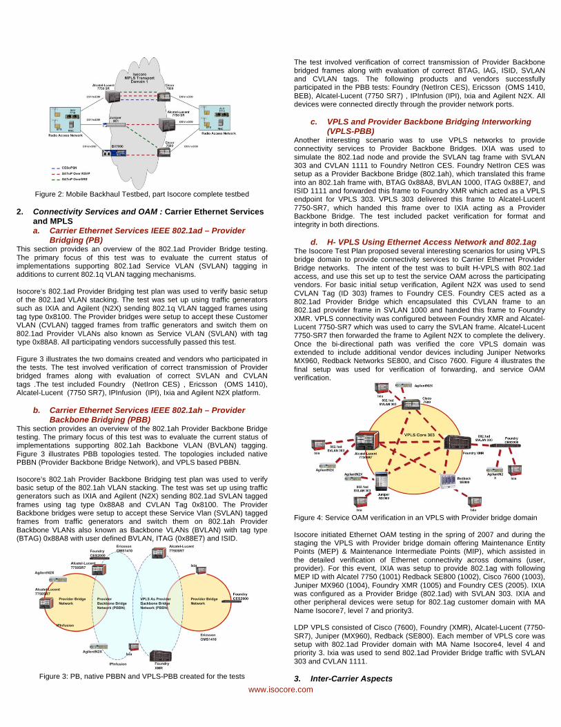
Figure 2: Mobile Backhaul Testbed, part Isocore complete testbed
2. Connectivity Services and OAM : Carrier Ethernet Services and MPLS a. Carrier Ethernet Services IEEE 802.1ad – Provider
Bridging (PB) This section provides an overview of the 802.1ad Provider Bridge testing.
The primary focus of this test was to evaluate the current status of implementations supporting 802.1ad Service VLAN (SVLAN) tagging in additions to current 802.1q VLAN tagging mechanisms.
Isocore’s 802.1ad Provider Bridging test plan was used to verify basic setup of the 802.1ad VLAN stacking. The test was set up using traffic generators
such as IXIA and Agilent (N2X) sending 802.1q VLAN tagged frames using tag type 0x8100. The Provider bridges were setup to accept these Customer VLAN (CVLAN) tagged frames from traffic generators and switch them on
802.1ad Provider VLANs also known as Service VLAN (SVLAN) with tag type 0x88A8. All participating vendors successfully passed this test.
Figure 3 illustrates the two domains created and vendors who participated in the tests. The test involved verification of correct transmission of Provider bridged frames along with evaluation of correct SVLAN and CVLAN
tags .The test included Foundry (NetIron CES) , Ericsson (OMS 1410), Alcatel-Lucent (7750 SR7), IPInfusion (IPI), Ixia and Agilent N2X platform.
b. Carrier Ethernet Services IEEE 802.1ah – Provider Backbone Bridging (PBB)
This section provides an overview of the 802.1ah Provider Backbone Bridge testing. The primary focus of this test was to evaluate the current status of implementations supporting 802.1ah Backbone VLAN (BVLAN) tagging.
Figure 3 illustrates PBB topologies tested. The topologies included native PBBN (Provider Backbone Bridge Network), and VPLS based PBBN.
Isocore’s 802.1ah Provider Backbone Bridging test plan was used to verify basic setup of the 802.1ah VLAN stacking. The test was set up using traffic generators such as IXIA and Agilent (N2X) sending 802.1ad SVLAN tagged
frames using tag type 0x88A8 and CVLAN Tag 0x8100. The Provider Backbone bridges were setup to accept these Service Vlan (SVLAN) tagged frames from traffic generators and switch them on 802.1ah Provider
Backbone VLANs also known as Backbone VLANs (BVLAN) with tag type (BTAG) 0x88A8 with user defined BVLAN, ITAG (0x88E7) and ISID.
Figure 3: PB, native PBBN and VPLS-PBB created for the tests
The test involved verification of correct transmission of Provider Backbone bridged frames along with evaluation of correct BTAG, IAG, ISID, SVLAN and CVLAN tags. The following products and vendors successfully participated in the PBB tests: Foundry (NetIron CES), Ericsson (OMS 1410,
BEB), Alcatel-Lucent (7750 SR7) , IPInfusion (IPI), Ixia and Agilent N2X. All devices were connected directly through the provider network ports.
c. VPLS and Provider Backbone Bridging Interworking (VPLS-PBB)
Another interesting scenario was to use VPLS networks to provide connectivity services to Provider Backbone Bridges. IXIA was used to
simulate the 802.1ad node and provide the SVLAN tag frame with SVLAN 303 and CVLAN 1111 to Foundry NetIron CES. Foundry NetIron CES was setup as a Provider Backbone Bridge (802.1ah), which translated this frame
into an 802.1ah frame with, BTAG 0x88A8, BVLAN 1000, ITAG 0x88E7, and ISID 1111 and forwarded this frame to Foundry XMR which acted as a VPLS endpoint for VPLS 303. VPLS 303 delivered this frame to Alcatel-Lucent
7750-SR7, which handed this frame over to IXIA acting as a Provider Backbone Bridge. The test included packet verification for format and integrity in both directions.
d. H- VPLS Using Ethernet Access Network and 802.1ag The Isocore Test Plan proposed several interesting scenarios for using VPLS bridge domain to provide connectivity services to Carrier Ethernet Provider
Bridge networks. The intent of the test was to built H-VPLS with 802.1ad access, and use this set up to test the service OAM across the participating vendors. For basic initial setup verification, Agilent N2X was used to send
CVLAN Tag (ID 303) frames to Foundry CES. Foundry CES acted as a 802.1ad Provider Bridge which encapsulated this CVLAN frame to an 802.1ad provider frame in SVLAN 1000 and handed this frame to Foundry
XMR. VPLS connectivity was configured between Foundry XMR and Alcatel-Lucent 7750-SR7 which was used to carry the SVLAN frame. Alcatel-Lucent 7750-SR7 then forwarded the frame to Agilent N2X to complete the delivery.
Once the bi-directional path was verified the core VPLS domain was extended to include additional vendor devices including Juniper Networks MX960, Redback Networks SE800, and Cisco 7600. Figure 4 illustrates the
final setup was used for verification of forwarding, and service OAM verification.
Figure 4: Service OAM verification in an VPLS with Provider bridge domain
Isocore initiated Ethernet OAM testing in the spring of 2007 and during the staging the VPLS with Provider bridge domain offering Maintenance Entity Points (MEP) & Maintenance Intermediate Points (MIP), which assisted in
the detailed verification of Ethernet connectivity across domains (user, provider). For this event, IXIA was setup to provide 802.1ag with following MEP ID with Alcatel 7750 (1001) Redback SE800 (1002), Cisco 7600 (1003),
Juniper MX960 (1004), Foundry XMR (1005) and Foundry CES (2005). IXIA was configured as a Provider Bridge (802.1ad) with SVLAN 303. IXIA and other peripheral devices were setup for 802.1ag customer domain with MA
Name Isocore7, level 7 and priority3. LDP VPLS consisted of Cisco (7600), Foundry (XMR), Alcatel-Lucent (7750-
SR7), Juniper (MX960), Redback (SE800). Each member of VPLS core was setup with 802.1ad Provider domain with MA Name Isocore4, level 4 and priority 3. Ixia was used to send 802.1ad Provider Bridge traffic with SVLAN
303 and CVLAN 1111.
3. Inter-Carrier Aspects
www.isocore.com
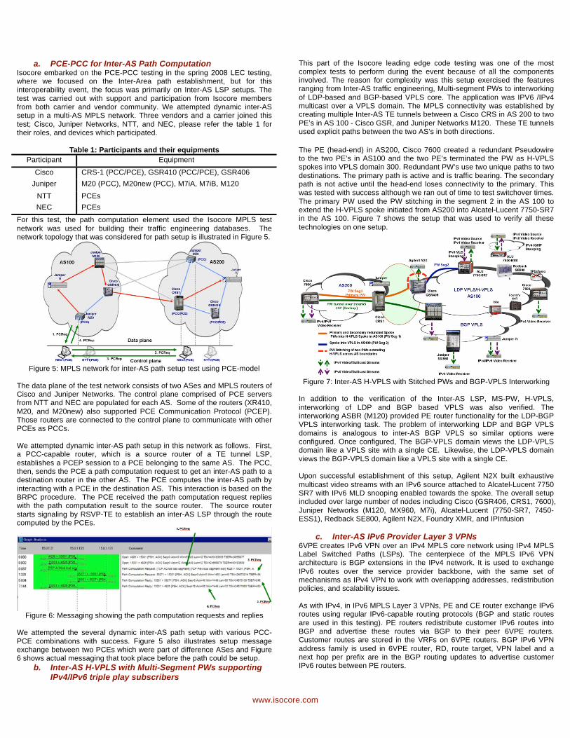
a. PCE-PCC for Inter-AS Path Computation Isocore embarked on the PCE-PCC testing in the spring 2008 LEC testing, where we focused on the Inter-Area path establishment, but for this interoperability event, the focus was primarily on Inter-AS LSP setups. The
test was carried out with support and participation from Isocore members from both carrier and vendor community. We attempted dynamic inter-AS setup in a multi-AS MPLS network. Three vendors and a carrier joined this
test; Cisco, Juniper Networks, NTT, and NEC, please refer the table 1 for their roles, and devices which participated.
Table 1: Participants and their equipments
Participant Equipment
Cisco CRS-1 (PCC/PCE), GSR410 (PCC/PCE), GSR406
Juniper M20 (PCC), M20new (PCC), M7iA, M7iB, M120
NTT PCEs
NEC PCEs
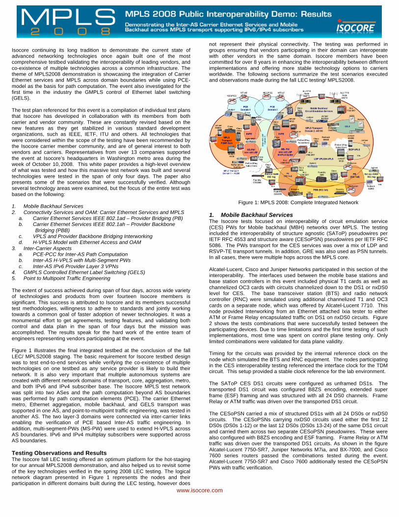
For this test, the path computation element used the Isocore MPLS test
network was used for building their traffic engineering databases. The network topology that was considered for path setup is illustrated in Figure 5.
Figure 5: MPLS network for inter-AS path setup test using PCE-model
The data plane of the test network consists of two ASes and MPLS routers of Cisco and Juniper Networks. The control plane comprised of PCE servers from NTT and NEC are populated for each AS. Some of the routers (XR410,
M20, and M20new) also supported PCE Communication Protocol (PCEP). Those routers are connected to the control plane to communicate with other PCEs as PCCs.
We attempted dynamic inter-AS path setup in this network as follows. First, a PCC-capable router, which is a source router of a TE tunnel LSP,
establishes a PCEP session to a PCE belonging to the same AS. The PCC, then, sends the PCE a path computation request to get an inter-AS path to a destination router in the other AS. The PCE computes the inter-AS path by
interacting with a PCE in the destination AS. This interaction is based on the BRPC procedure. The PCE received the path computation request replies with the path computation result to the source router. The source router
starts signaling by RSVP-TE to establish an inter-AS LSP through the route computed by the PCEs.
Figure 6: Messaging showing the path computation requests and replies
We attempted the several dynamic inter-AS path setup with various PCC-
PCE combinations with success. Figure 5 also illustrates setup message exchange between two PCEs which were part of difference ASes and Figure 6 shows actual messaging that took place before the path could be setup.
b. Inter-AS H-VPLS with Multi-Segment PWs supporting IPv4/IPv6 triple play subscribers
This part of the Isocore leading edge code testing was one of the most complex tests to perform during the event because of all the components involved. The reason for complexity was this setup exercised the features ranging from Inter-AS traffic engineering, Multi-segment PWs to interworking
of LDP-based and BGP-based VPLS core. The application was IPV6 /IPv4 multicast over a VPLS domain. The MPLS connectivity was established by creating multiple Inter-AS TE tunnels between a Cisco CRS in AS 200 to two
PE’s in AS 100 - Cisco GSR, and Juniper Networks M120. These TE tunnels used explicit paths between the two AS’s in both directions.
The PE (head-end) in AS200, Cisco 7600 created a redundant Pseudowire to the two PE’s in AS100 and the two PE’s terminated the PW as H-VPLS spokes into VPLS domain 300. Redundant PW’s use two unique paths to two
destinations. The primary path is active and is traffic bearing. The secondary path is not active until the head-end loses connectivity to the primary. This was tested with success although we ran out of time to test switchover times.
The primary PW used the PW stitching in the segment 2 in the AS 100 to extend the H-VPLS spoke initiated from AS200 into Alcatel-Lucent 7750-SR7 in the AS 100. Figure 7 shows the setup that was used to verify all these
technologies on one setup.
Figure 7: Inter-AS H-VPLS with Stitched PWs and BGP-VPLS Interworking
In addition to the verification of the Inter-AS LSP, MS-PW, H-VPLS,
interworking of LDP and BGP based VPLS was also verified. The interworking ASBR (M120) provided PE router functionality for the LDP-BGP VPLS interworking task. The problem of interworking LDP and BGP VPLS
domains is analogous to inter-AS BGP VPLS so similar options were configured. Once configured, The BGP-VPLS domain views the LDP-VPLS domain like a VPLS site with a single CE. Likewise, the LDP-VPLS domain
views the BGP-VPLS domain like a VPLS site with a single CE. Upon successful establishment of this setup, Agilent N2X built exhaustive
multicast video streams with an IPv6 source attached to Alcatel-Lucent 7750 SR7 with IPv6 MLD snooping enabled towards the spoke. The overall setup included over large number of nodes including Cisco (GSR406, CRS1, 7600),
Juniper Networks (M120, MX960, M7i), Alcatel-Lucent (7750-SR7, 7450-ESS1), Redback SE800, Agilent N2X, Foundry XMR, and IPInfusion
c. Inter-AS IPv6 Provider Layer 3 VPNs 6VPE creates IPv6 VPN over an IPv4 MPLS core network using IPv4 MPLS Label Switched Paths (LSPs). The centerpiece of the MPLS IPv6 VPN architecture is BGP extensions in the IPv4 network. It is used to exchange
IPv6 routes over the service provider backbone, with the same set of mechanisms as IPv4 VPN to work with overlapping addresses, redistribution policies, and scalability issues.
As with IPv4, in IPv6 MPLS Layer 3 VPNs, PE and CE router exchange IPv6 routes using regular IPv6-capable routing protocols (BGP and static routes
are used in this testing). PE routers redistribute customer IPv6 routes into BGP and advertise these routes via BGP to their peer 6VPE routers. Customer routes are stored in the VRFs on 6VPE routers. BGP IPv6 VPN
address family is used in 6VPE router, RD, route target, VPN label and a next hop per prefix are in the BGP routing updates to advertise customer IPv6 routes between PE routers.
www.isocore.com
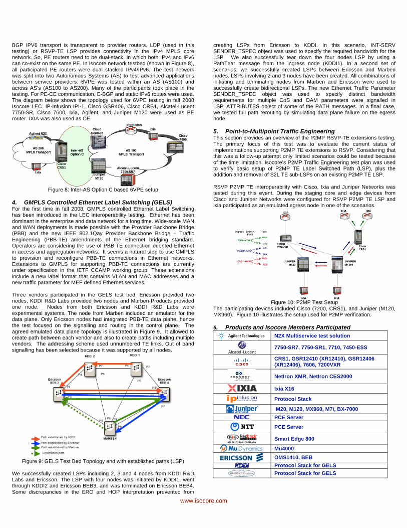
BGP IPV6 transport is transparent to provider routers. LDP (used in this testing) or RSVP-TE LSP provides connectivity in the IPv4 MPLS core network. So, PE routers need to be dual-stack, in which both IPv4 and IPv6 can co-exist on the same PE. In Isocore network testbed (shown in Figure 8),
all participated PE routers were dual stacked IPv4/IPv6. The test network was split into two Autonomous Systems (AS) to test advanced applications between service providers. 6VPE was tested within an AS (AS100) and
across AS’s (AS100 to AS200). Many of the participants took place in the testing. For PE-CE communication, E-BGP and static IPv6 routes were used. The diagram below shows the topology used for 6VPE testing in fall 2008
Isocore LEC. IP-Infusion IPI-1, Cisco GSR406, Cisco CRS1, Alcatel-Lucent 7750-SR, Cisco 7600, Ixia, Agilent, and Juniper M120 were used as PE router. IXIA was also used as CE.
Figure 8: Inter-AS Option C based 6VPE setup
4. GMPLS Controlled Ethernet Label Switching (GELS) For the first time in fall 2008, GMPLS controlled Ethernet Label Switching has been introduced in the LEC interoperability testing. Ethernet has been
dominant in the enterprise and data network for a long time. Wide-scale MAN and WAN deployments is made possible with the Provider Backbone Bridge (PBB) and the new IEEE 802.1Qay Provider Backbone Bridge – Traffic
Engineering (PBB-TE) amendments of the Ethernet bridging standard. Operators are considering the use of PBB-TE connection oriented Ethernet in access and aggregation networks. It seems a natural step to use GMPLS
to provision and reconfigure PBB-TE connections in Ethernet networks. Extensions to GMPLS for supporting PBB-TE connections are currently under specification in the IETF CCAMP working group. These extensions
include a new label format that contains VLAN and MAC addresses and a new traffic parameter for MEF defined Ethernet services.
Three vendors participated in the GELS test bed. Ericsson provided two nodes, KDDI R&D Labs provided two nodes and Marben-Products provided one node. Nodes from both Ericsson and KDDI R&D Labs were
experimental systems. The node from Marben included an emulator for the data plane. Only Ericsson nodes had integrated PBB-TE data plane, hence the test focused on the signalling and routing in the control plane. The
agreed emulated data plane topology is illustrated in Figure 9. It allowed to create path between each vendor and also to create paths including multiple vendors. The addressing scheme used unnumbered TE links. Out of band
signalling has been selected because it was supported by all nodes.
Figure 9: GELS Test Bed Topology and with established paths (LSP)
We successfully created LSPs including 2, 3 and 4 nodes from KDDI R&D Labs and Ericsson. The LSP with four nodes was initiated by KDDI1, went through KDDI2 and Ericsson BEB3, and was terminated on Ericsson BEB4.
Some discrepancies in the ERO and HOP interpretation prevented from
creating LSPs from Ericsson to KDDI. In this scenario, INT-SERV SENDER_TSPEC object was used to specify the required bandwidth for the LSP. We also successfully tear down the four nodes LSP by using a PathTear message from the ingress node (KDDI1). In a second set of
scenarios, we successfully created LSPs between Ericsson and Marben nodes. LSPs involving 2 and 3 nodes have been created. All combinations of initiating and terminating nodes from Marben and Ericsson were used to
successfully create bidirectional LSPs. The new Ethernet Traffic Parameter SENDER_TSPEC object was used to specify distinct bandwidth requirements for multiple CoS and OAM parameters were signalled in
LSP_ATTRIBUTES object of some of the PATH messages. In a final case, we tested full path rerouting by simulating data plane failure on the egress node.
5. Point-to-Multipoint Traffic Engineering This section provides an overview of the P2MP RSVP-TE extensions testing.
The primary focus of this test was to evaluate the current status of implementations supporting P2MP TE extensions to RSVP. Considering that this was a follow-up attempt only limited scenarios could be tested because
of the time limitation. Isocore’s P2MP Traffic Engineering test plan was used to verify basic setup of P2MP TE Label Switched Path (LSP), plus the addition and removal of S2L TE sub-LSPs on an existing P2MP TE LSP.
RSVP P2MP TE interoperability with Cisco, Ixia and Juniper Networks was tested during this event. During the staging core and edge devices from
Cisco and Juniper Networks were configured for RSVP P2MP TE LSP and ixia participated as an emulated egress node in one of the scenarios.
Figure 10: P2MP Test Setup
The participating devices included Cisco (7200, CRS1), and Juniper (M120, MX960). Figure 10 illustrates the setup used for P2MP verification.
6. Products and Isocore Members Participated
N2X Multiservice test solution
7750-SR7, 7750-SR1, 7710, 7450-ESS
CRS1, GSR12410 (XR12410), GSR12406 (XR12406), 7606, 7200VXR
NetIron XMR, NetIron CES2000
Ixia X16
Protocol Stack
M20, M120, MX960, M7i, BX-7000
PCE Server
PCE Server
Smart Edge 800
Mu4000
OMS1410, BEB
Protocol Stack for GELS
Protocol Stack for GELS