Embed Size (px)
Citation preview

1
Lecture 5Lecture 5
Object-Oriented Analysis

2
Disclaimer and Copyright Notice
This work is subject to copyright. All rights are reserved.
This course material is developed in conjunction with the courseware of Software Engineering: A Practitioner’s
Approach, 5/e and are provided with permission by R.S. Pressman & Associates, Inc., copyright © 1996, 2001.
The material provided is for reference only. It should not be redistributed with prior written consent. Proceeding beyond this notice implies willingness to comply with the terms.
3
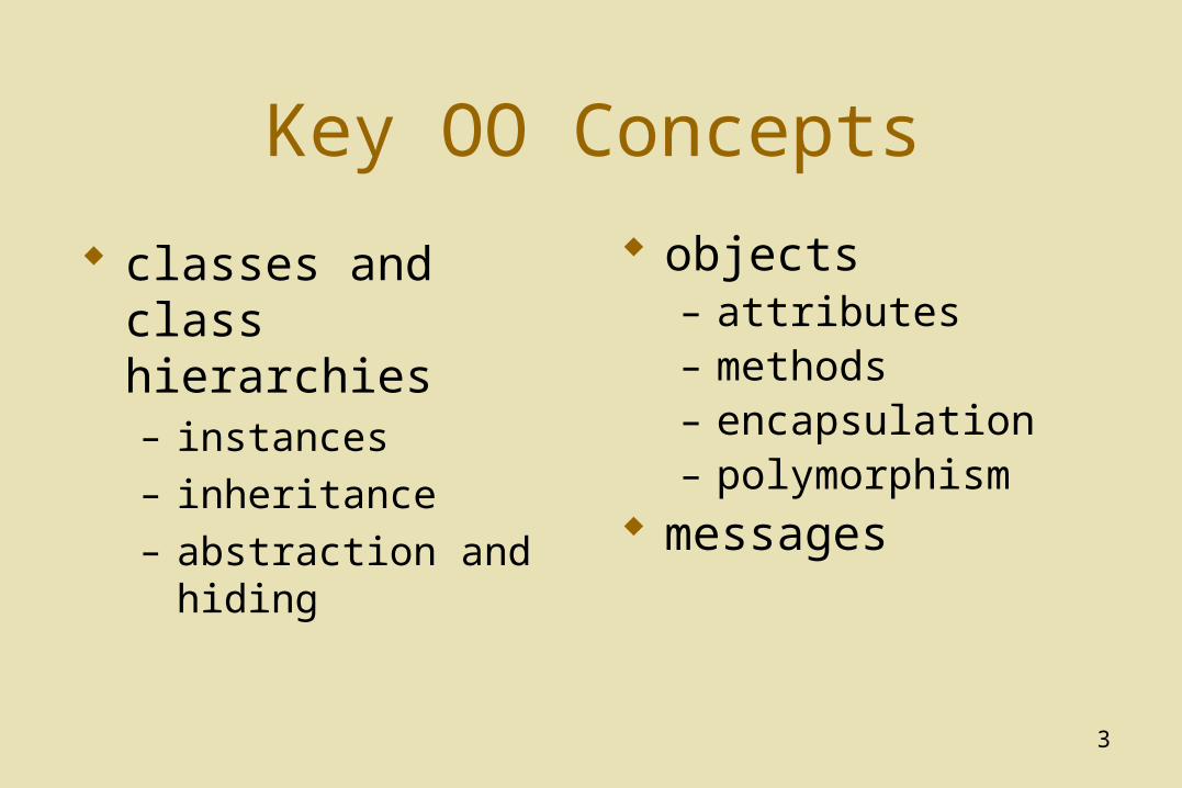
Key OO Concepts
classes and class hierarchies– instances– inheritance– abstraction and hiding
objects– attributes– methods– encapsulation– polymorphism
messages
4
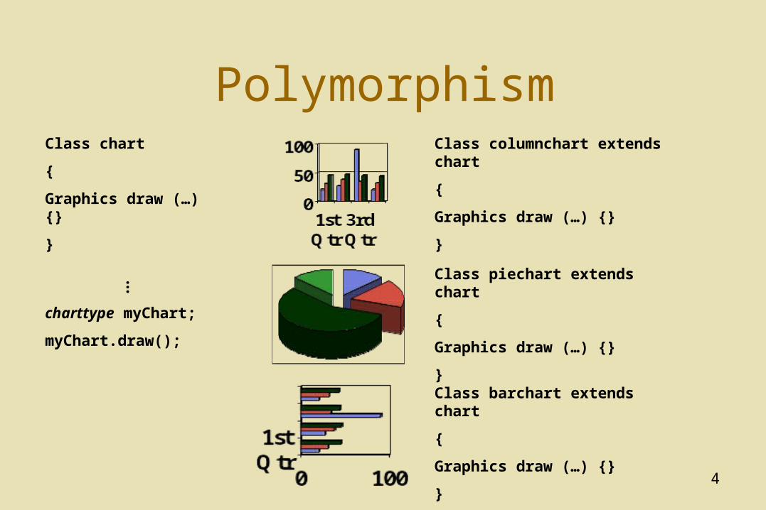
PolymorphismClass chart
{
Graphics draw (…) {}
}
...
charttype myChart;
myChart.draw();
Class columnchart extends chart
{
Graphics draw (…) {}
}
Class piechart extends chart
{
Graphics draw (…) {}
}
Class barchart extends chart
{
Graphics draw (…) {}
}
5
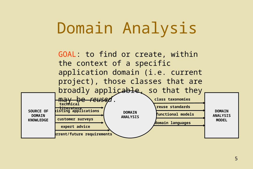
Domain Analysis
technical literature
existing applications
customer surveys
expert advice
current/future requirements
SOURCE OF DOMAIN
KNOWLEDGE
DOMAIN ANALYSIS
DOMAIN ANALYSIS
MODEL
class taxonomies
reuse standards
functional models
domain languages
GOAL: to find or create, within the context of a specific application domain (i.e. current project), those classes that are broadly applicable, so that they may be reused.
6
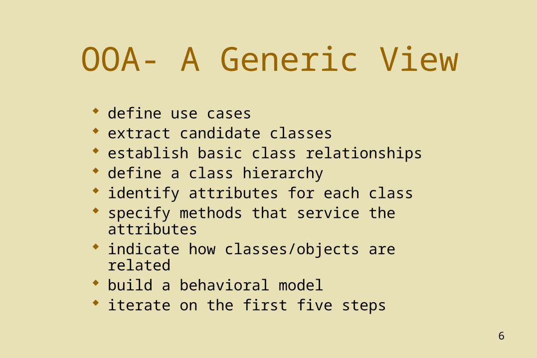
OOA- A Generic View
define use cases extract candidate classes establish basic class relationships define a class hierarchy identify attributes for each class specify methods that service the attributes indicate how classes/objects are related build a behavioral model iterate on the first five steps
7
Use Cases
a scenario that describes a “thread of usage” for a system
actors represent roles people or devices play as the system functions
users can play a number of different roles for a given scenario
8
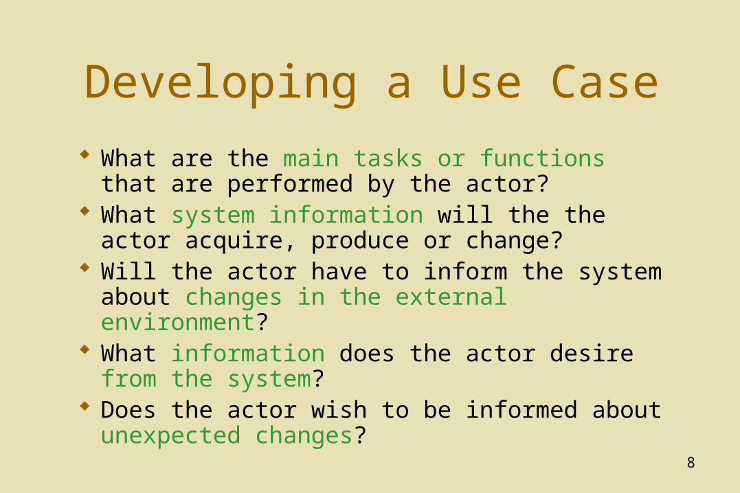
Developing a Use Case
What are the main tasks or functions that are performed by the actor?
What system information will the the actor acquire, produce or change?
Will the actor have to inform the system about changes in the external environment?
What information does the actor desire from the system?
Does the actor wish to be informed about unexpected changes?
9
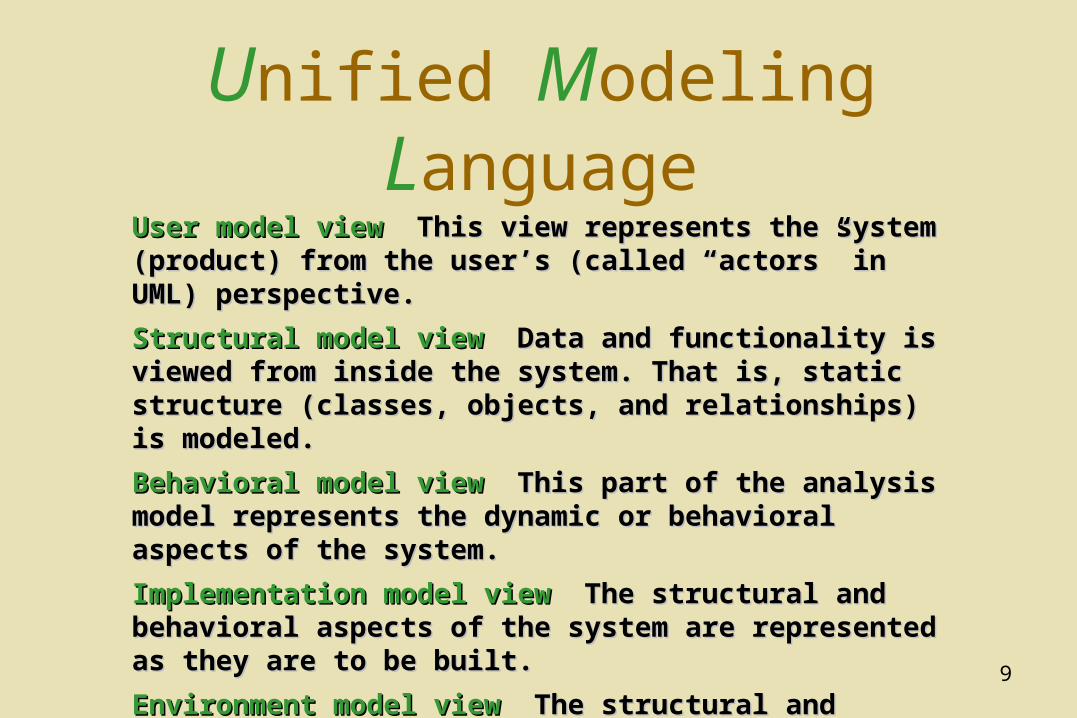
Unified Modeling Language
User model viewUser model view This view represents the system (product) This view represents the system (product) from the user’s (called “actors” in UML) perspective.from the user’s (called “actors” in UML) perspective.
Structural model viewStructural model view Data and functionality is viewed from Data and functionality is viewed from inside the system. That is, static structure (classes, objects, inside the system. That is, static structure (classes, objects, and relationships) is modeled.and relationships) is modeled.
Behavioral model viewBehavioral model view This part of the analysis model This part of the analysis model represents the dynamic or behavioral aspects of the system. represents the dynamic or behavioral aspects of the system.
Implementation model viewImplementation model view The structural and behavioral The structural and behavioral aspects of the system are represented as they are to be built.aspects of the system are represented as they are to be built.
Environment model viewEnvironment model view The structural and behavioral The structural and behavioral aspects of the environment in which the system is to be aspects of the environment in which the system is to be implemented are represented.implemented are represented.
10
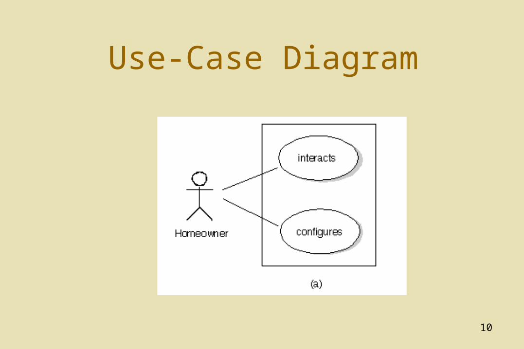
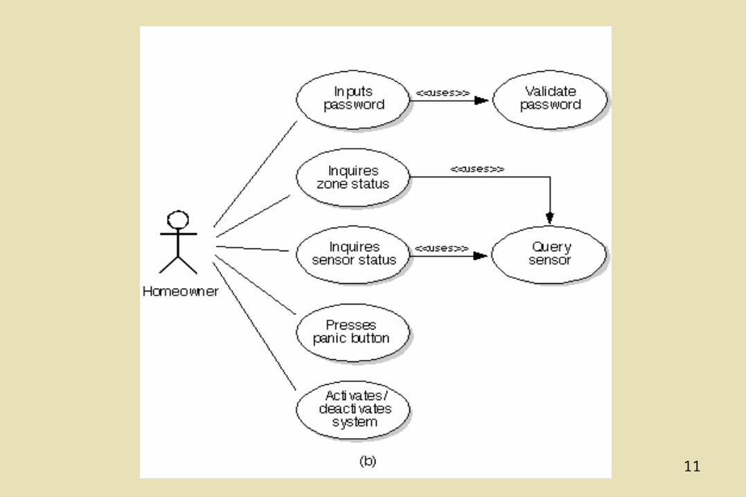
Use-Case Diagram
11
12
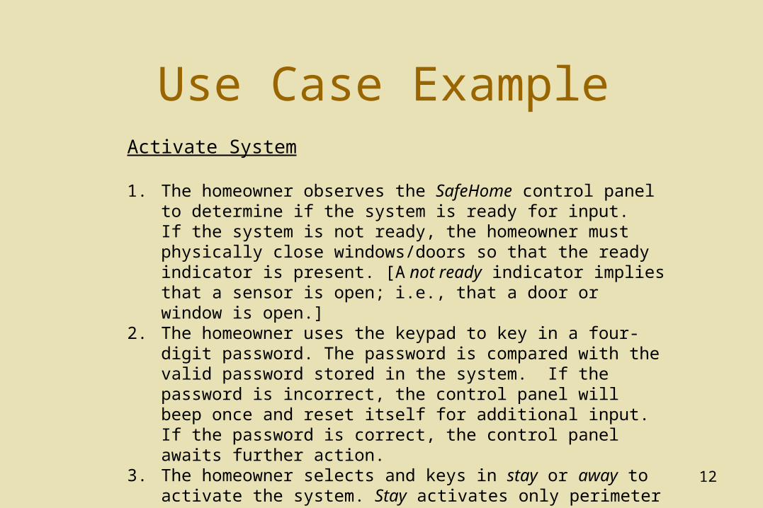
Use Case ExampleActivate System
1. The homeowner observes the SafeHome control panel to determine if the system is ready for input. If the system is not ready, the homeowner must physically close windows/doors so that the ready indicator is present. [A not ready indicator implies that a sensor is open; i.e., that a door or window is open.]
2. The homeowner uses the keypad to key in a four-digit password. The password is compared with the valid password stored in the system. If the password is incorrect, the control panel will beep once and reset itself for additional input. If the password is correct, the control panel awaits further action.
3. The homeowner selects and keys in stay or away to activate the system. Stay activates only perimeter sensors (inside motion detecting sensors are deactivated). Away activates all sensors.
4. When activation occurs, a red alarm light can be observed by the homeowner.
13
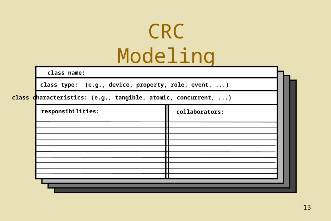
CRC Modeling
class name:
class type: (e.g., device, property, role, event, ...)
class characteristics: (e.g., tangible, atomic, concurrent, ...)
responsibilities: collaborators:
14
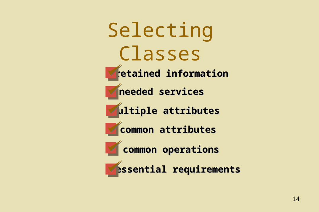
Selecting Classes
needed servicesneeded services
multiple attributesmultiple attributes
common attributescommon attributes
common operationscommon operations
essential requirementsessential requirements
retained informationretained information
15
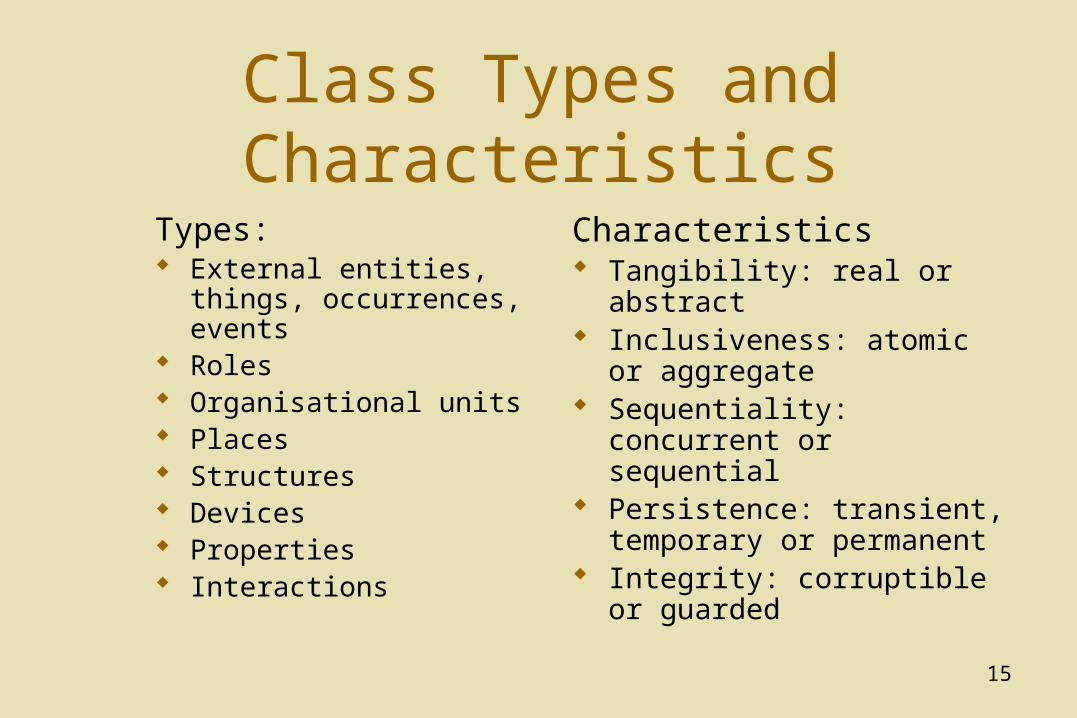
Class Types and Characteristics
Types: External entities, things,
occurrences, events Roles Organisational units Places Structures Devices Properties Interactions
Characteristics Tangibility: real or abstract Inclusiveness: atomic or
aggregate Sequentiality: concurrent or
sequential Persistence: transient,
temporary or permanent Integrity: corruptible or
guarded
16
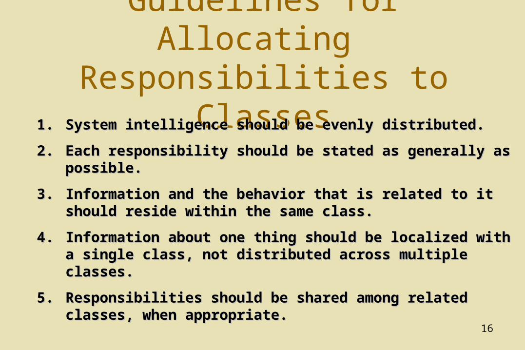
Guidelines for Allocating Responsibilities to Classes
1.1. System intelligence should be evenly distributed. System intelligence should be evenly distributed.
2.2. Each responsibility should be stated as generally as Each responsibility should be stated as generally as possible. possible.
3.3. Information and the behavior that is related to it should Information and the behavior that is related to it should reside within the same class. reside within the same class.
4.4. Information about one thing should be localized with a Information about one thing should be localized with a single class, not distributed across multiple classes.single class, not distributed across multiple classes.
5.5. Responsibilities should be shared among related classes, Responsibilities should be shared among related classes, when appropriate.when appropriate.
17
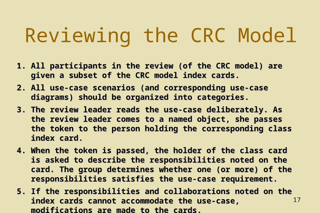
Reviewing the CRC Model1.1. All participants in the review (of the CRC model) are given a subset of All participants in the review (of the CRC model) are given a subset of
the CRC model index cards. the CRC model index cards.
2.2. All use-case scenarios (and corresponding use-case diagrams) should All use-case scenarios (and corresponding use-case diagrams) should be organized into categories.be organized into categories.
3.3. The review leader reads the use-case deliberately. As the review leader The review leader reads the use-case deliberately. As the review leader comes to a named object, she passes the token to the person holding comes to a named object, she passes the token to the person holding the corresponding class index card. the corresponding class index card.
4.4. When the token is passed, the holder of the class card is asked to When the token is passed, the holder of the class card is asked to describe the responsibilities noted on the card. The group determines describe the responsibilities noted on the card. The group determines whether one (or more) of the responsibilities satisfies the use-case whether one (or more) of the responsibilities satisfies the use-case requirement.requirement.
5.5. If the responsibilities and collaborations noted on the index cards If the responsibilities and collaborations noted on the index cards cannot accommodate the use-case, modifications are made to the cannot accommodate the use-case, modifications are made to the cards.cards.
18
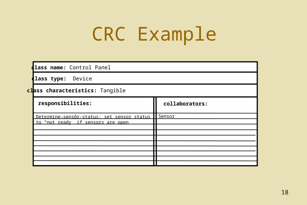
CRC Example
class name: Control Panel
class type: Device
class characteristics: Tangible
responsibilities: collaborators:
Determine-sensor-status: set sensor status to “not ready” if sensors are open
Sensor
19
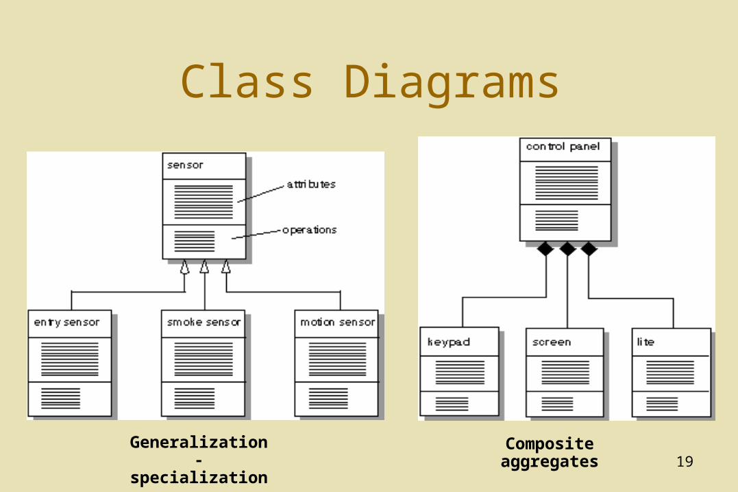
Class Diagrams
Generalization-specialization
Composite aggregates
20
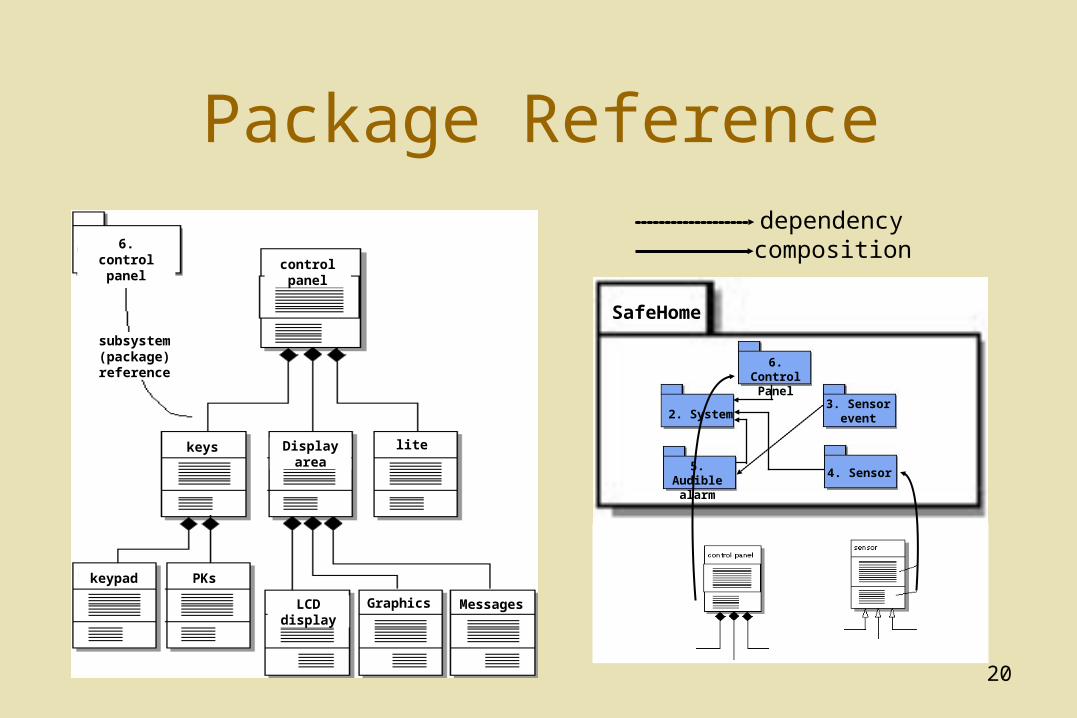
Package Reference
SafeHome
6. Control Panel
2. System
5. Audible alarm
3. Sensor event
4. Sensor
6. control panel control panel
keys Display area lite
keypad PKs
LCD display Graphics Messages
subsystem(package)reference
dependencycomposition
21
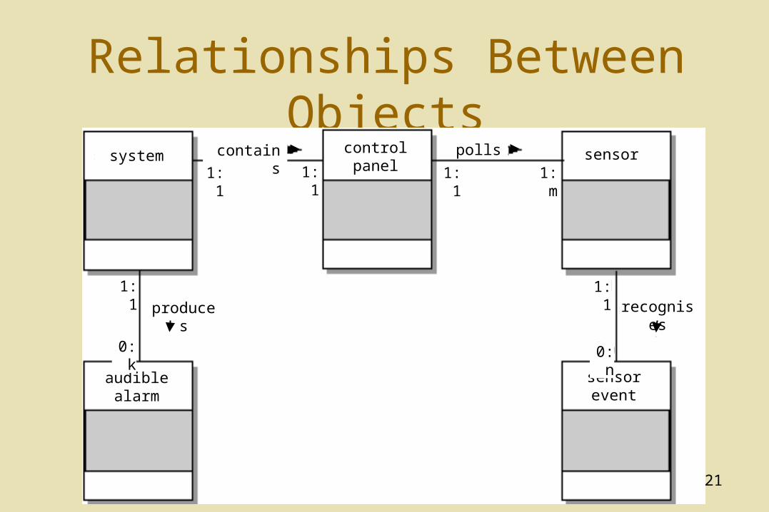
Relationships Between Objectscontainssystem control
panelsensor
sensor event
audible alarm
produces
polls
recognises1:1
1:1 1:1 1:1
1:1
1:m
0:k 0:n
22
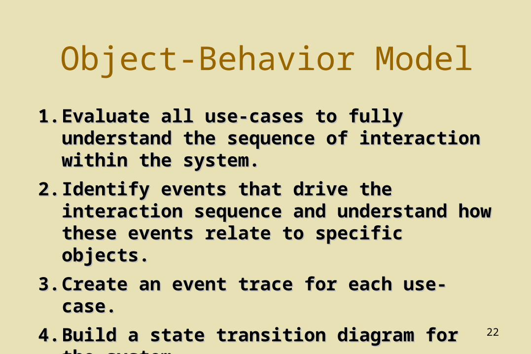
Object-Behavior Model
1.1. Evaluate all use-cases to fully understand the Evaluate all use-cases to fully understand the sequence of interaction within the system.sequence of interaction within the system.
2.2. Identify events that drive the interaction Identify events that drive the interaction sequence and understand how these events sequence and understand how these events relate to specific objects.relate to specific objects.
3.3. Create an event trace for each use-case.Create an event trace for each use-case.
4.4. Build a state transition diagram for the systemBuild a state transition diagram for the system
5.5. Review the object-behavior model to verify Review the object-behavior model to verify accuracy and consistency.accuracy and consistency.
23
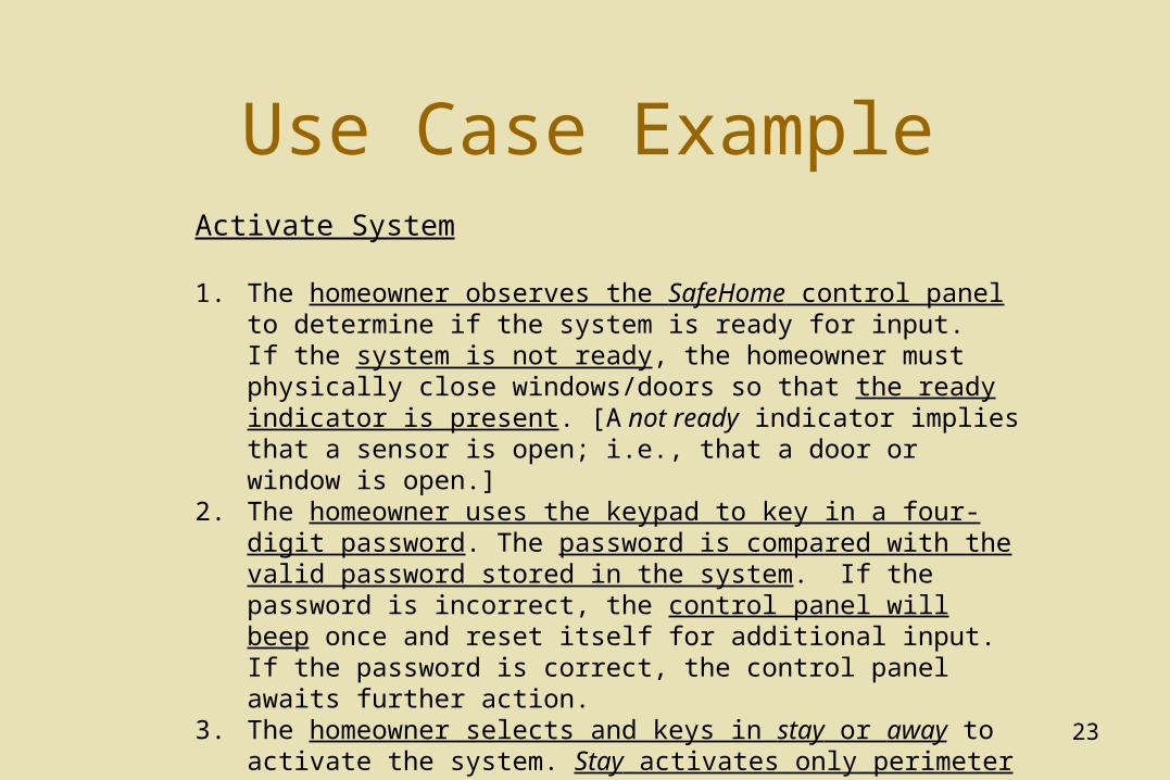
Use Case ExampleActivate System
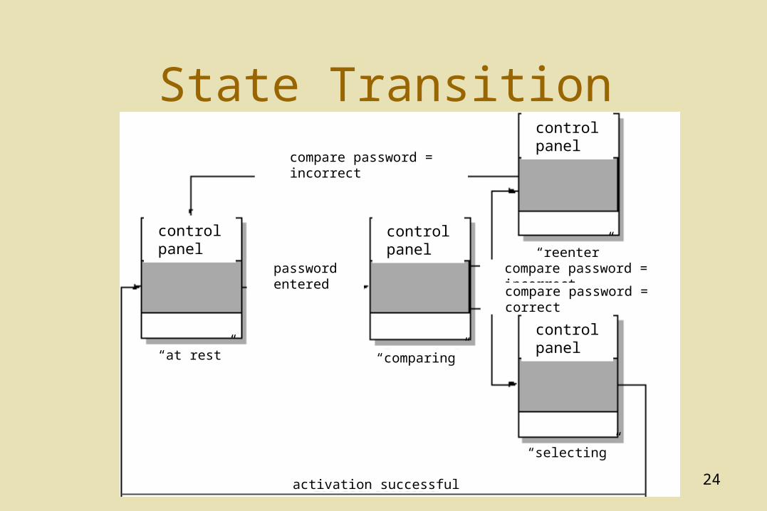
1. The homeowner observes the SafeHome control panel to determine if the system is ready for input. If the system is not ready, the homeowner must physically close windows/doors so that the ready indicator is present. [A not ready indicator implies that a sensor is open; i.e., that a door or window is open.]
2. The homeowner uses the keypad to key in a four-digit password. The password is compared with the valid password stored in the system. If the password is incorrect, the control panel will beep once and reset itself for additional input. If the password is correct, the control panel awaits further action.
3. The homeowner selects and keys in stay or away to activate the system. Stay activates only perimeter sensors (inside motion detecting sensors are deactivated). Away activates all sensors.
4. When activation occurs, a red alarm light can be observed by the homeowner.
24
State Transition
control panel control panel
control panel
control panel“at rest” “comparing”
“selecting”
“reenter”
compare password = incorrect
password entered compare password = incorrect
compare password = correct
activation successful
25
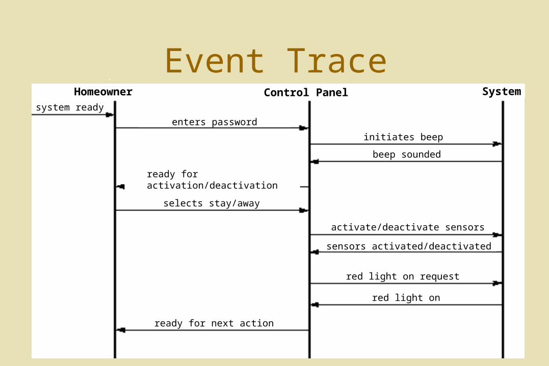
Event Trace
enters password
ready for activation/deactivation
selects stay/away
ready for next action
initiates beep
beep sounded
activate/deactivate sensors
sensors activated/deactivated
red light on request
red light on
system ready
Homeowner Control Panel System
26
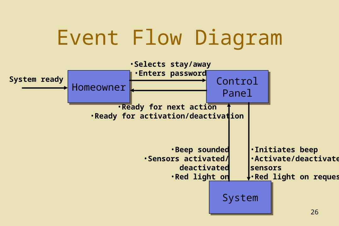
Event Flow Diagram
HomeownerHomeowner Control PanelControl Panel
SystemSystem
•Beep sounded•Sensors activated/
deactivated•Red light on
•Initiates beep•Activate/deactivatesensors•Red light on request
•Selects stay/away•Enters password
•Ready for next action•Ready for activation/deactivation
System ready
27
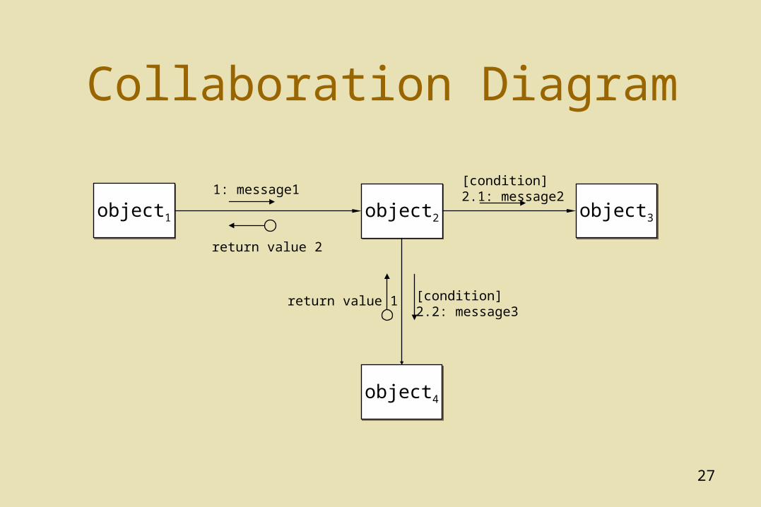
Collaboration Diagram
object1object1 object3object3object2object2
object4object4
1: message1[condition]2.1: message2
[condition]2.2: message3
return value 1
return value 2
28
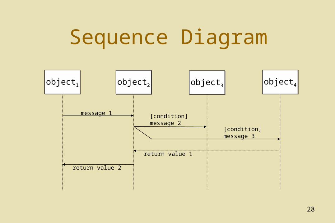
Sequence Diagram
object1object1 object3object3object2object2 object4object4
message 1
return value 2
[condition]message 2
[condition]message 3
return value 1
29
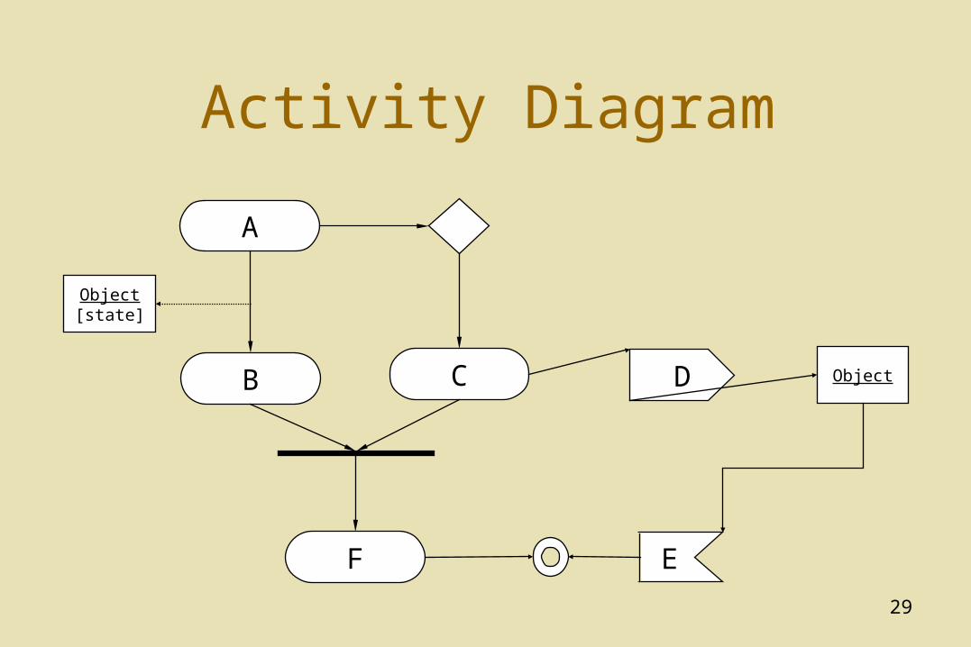
Activity Diagram
A
B C
F
Object[state]
D
E
Object
30
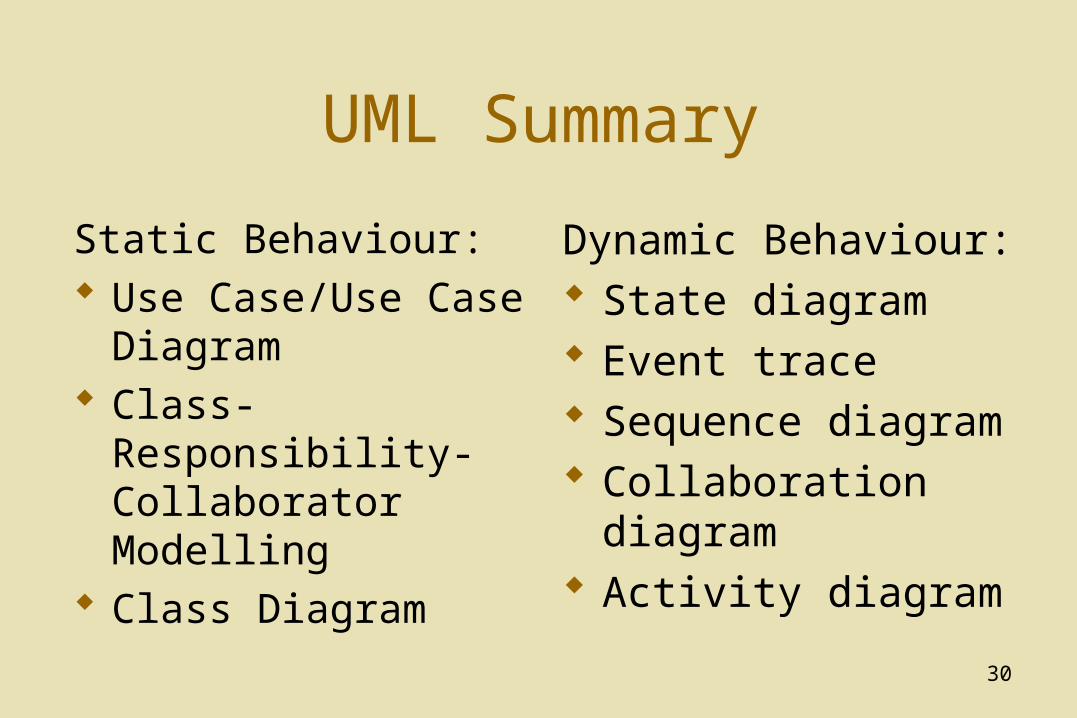
UML Summary
Static Behaviour: Use Case/Use Case
Diagram Class-Responsibility-
Collaborator Modelling Class Diagram
Dynamic Behaviour: State diagram Event trace Sequence diagram Collaboration diagram Activity diagram