Embed Size (px)
Citation preview

Preface
PrefaceCopyrightThis publication, including all photographs, illustrations and software, is protectedunder international copyright laws, with all rights reserved. Neither this manual, norany of the material contained herein, may be reproduced without written consent ofthe author.
Version 1.0C
DisclaimerThe information in this document is subject to change without notice. The manufac-turer makes no representations or warranties with respect to the contents hereof andspecifically disclaims any implied warranties of merchantability or fitness for anyparticular purpose. The manufacturer reserves the right to revise this publication andto make changes from time to time in the content hereof without obligation of themanufacturer to notify any person of such revision or changes.
Trademark RecognitionMicrosoft, MS-DOS and Windows are registered trademarks of Microsoft Corp.
MMX, Pentium, Pentium-II, Pentium-III, Celeron are registered trademarks of IntelCorporation.
Other product names used in this manual are the properties of their respectiveowners and are acknowledged.
Federal Communications Commission (FCC)This equipment has been tested and found to comply with the limits for a Class Bdigital device, pursuant to Part 15 of the FCC Rules. These limits are designed toprovide reasonable protection against harmful interference in a residential installa-tion. This equipment generates, uses, and can radiate radio frequency energy and, ifnot installed and used in accordance with the instructions, may cause harmful inter-ference to radio communications. However, there is no guarantee that interferencewill not occur in a particular installation. If this equipment does cause harmfulinterference to radio or television reception, which can be determined by turning theequipment off and on, the user is encouraged to try to correct the interference by oneor more of the following measures:
• Reorient or relocate the receiving antenna• Increase the separation between the equipment and the receiver• Connect the equipment onto an outlet on a circuit different from that to
which the receiver is connected• Consult the dealer or an experienced radio/TV technician for help
Shielded interconnect cables and a shielded AC power cable must be employed withthis equipment to ensure compliance with the pertinent RF emission limits governingthis device. Changes or modifications not expressly approved by the system’s manu-facturer could void the user’s authority to operate the equipment.

ii
Preface
Declaration of ConformityThis device complies with part 15 of the FCC rules. Operation is subject to thefollowing conditions:
• This device may not cause harmful interference.• This device must accept any interference received, including interfer-
ence that may cause undesired operation.
Canadian Department of CommunicationsThis class B digital apparatus meets all requirements of the Canadian Interference-causing Equipment Regulations.Cet appareil numérique de la classe B respecte toutes les exigences du Réglement surle matériel brouilieur du Canada.
About the ManualThe manual consists of the following:
Describes features of themotherboard.
Go to page 1
Describes installation ofmotherboard components.
Go to page 9
Go to page 29
Go to page 63
Describes the motherboardsoftware
Chapter 2
Installing the Motherboard
Chapter 1
Introducing the Motherboard
Chapter 3
Using BIOS
Chapter 4
Using the Motherboard Software
Chatper 5
Trouble Shooting Provides basic trouble shoot
ing tipspage 67Go to
Provides information on usingthe BIOS Setup Utility.

iii
Chapter 2 9Installing the Motherboard 9
Safety Precautions............................................................................9Choosing a Computer Case.............................................................9Installing the Motherboard in a Case............................................9Checking Jumper Settings.............................................................10 Setting Jumpers......................................................................10 Checking Jumper Settings......................................................11
Jumper Settings......................................................................11 Installing Hardware...................................................................12
Installing the Processor..........................................................12 Installing Memory Modules...................................................14 Expansion Slots......................................................................16 Connecting Optional Devices.................................................18
Installing a SATA Hard Drive................................................22 Connecting I/O Devices............................................................... 23Connecting Case Components.....................................................24
Front Panel Header................................................................27
TTTTTABLE OF CONTENTSABLE OF CONTENTSABLE OF CONTENTSABLE OF CONTENTSABLE OF CONTENTS
Preface i
Chapter 1 1Introducing the Motherboard 1
Introduction...................................................................................1 Feature............................................................................................2 Specifications................................................................................4 Motherboard Components..........................................................6
Chapter 3 29Using BIOS 29
About the Setup Utility........................ ......................................... 29 The Standard Configuration........................ ...........................29
Entering the Setup Utility......................................................29Resetting the Default CMOS Values....................................30
Using BIOS......................................................................................30 BIOS Navigation Key.............................................................31
Main Menu.............................................................................32 Advanced Menu......................................................................33
Chipset Menu..........................................................................45 M.I.B.III (MB Intelligent Bios III) Menu.................................52 Boot Menu...............................................................................55

iv
Security Menu.........................................................................57 Exit Menu...............................................................................60 Updating the BIOS..................................................................61
Chapter 4 63Using the Motherboard Software 63
Auto-installing under Windows XP/7/8.......................................63 Running Setup.........................................................................63Manual Installation...........................................................................65ECS Utility Software .......................................................................65
Chapter 5 67Trouble Shooting 67
Start up problems during assembly..............................................67Start up problems after prolong use............................................68Maintenance and care tips..............................................................68Basic Troubleshooting Flowchart...................................................69

1
Introducing the Motherboard
Chapter 1Introducing the Motherboard
IntroductionThank you for choosing H67H2-M2 motherboard. This motherboard is a highperformance, enhanced-function motherboard designed to support the LGA1155socket for new 2nd & 3rd Generation Intel® CoreTM Family/ Pentium® / Celeron®
processors*1. To reach the optimum system performance. Combined with ECSunique M.I.B III BIOS interface, it makes a simple, fast platform for high-endbusiness or personal desktop market.
This motherboard is based on Intel® H67 Chipset for best desktop platform solution.H67 is a single-chip, highly integrated, high performance Hyper-Threading periph-eral controller, unmatched by any other single-chip device controller. Thismotherboard supports up to 16 GB of system memory with dual channel DDR31600*2/1333/1066 SDRAM. It cooperates one PCIe 16X graphic interface. It alsoprovides two PCI rev 3.0 slots and one PCI Express x1 rev 2.0 slot for extendingusage. It implements an EHCI compliant interface that provides twelve USB 2.0ports (four USB ports and four USB 2.0 headers support additional eight USB ports).The gray USB 2.0 header provides EZ charger technology, please refer to chapter2 of Front Panel USB headers to check the detail information. This motherboardimplements extra USB 3.0 chip which provide two USB3.0 ports*3 at rear I/O withblue connector (USB 3.0 feature is optional) also.
The motherboard is equipped with advanced full set of I/O ports in the rear panel,including one PS/2 keyboard and PS/2 mouse connector, one Ethernet LAN port,four USB 2.0 ports, two USB 3.0 ports (blue connector) running at 5 Gb/s, one D-sub (VGA) port, One DVI port (HDMI Port Optional), one Audio Port formicrophone, line-in, line-out and optical SPIDF out.
In addition, this motherboard supports two SATA 6Gb/s connectors and four SATA3Gb/s connectors for expansion.
*3 The USB 3.0 connectors are optimized for SuperSpeed USB 3.0 devices,aslo are fully backwards-compatible with Hi-Speed USB 2.0 devices.
*1 When accommodating Intel 3rd Generation CPU, the PCI Express 16Xslot can run at Gen3 speed, which accelerates on 32GB/s rate that effectivelydelivers double of PCI Express Gen2 speed.
*2 When you use this MB with 3rd Generation Intel® CoreTM Family Proces-sors.

2
Introducing the Motherboard
Feature
• Accommodates LGA1155 socket for new 2nd & 3rd Generation Intel®CoreTM Family/ Pentium® / Celeron® processors
• Supports “Hyper-Threading” technology CPU• One PCI Express x16 slot supporting up to 5 GB/s direction peak band-
width “Hyper-Threading” technology enables the operating system into thinking it’s hooked up to two processors, allowing two threads to be run in parallel, both on separate “logical” processors within the same physical processor.
The motherboard uses an LGA1155 type of socket that carries the followingfeatures:
Processor
ChipsetThe Intel® H67 Chipset is a single-chip with proven reliability and performance.
• Supports one PCI Express x1 Gen2 slot• Integrated four SATA 3.0 Gb/s ports and two SATA 6.0 Gb/s ports• Twelve USB 2.0 ports supported• Serial Peripheral Interface (SPI) support• Integrated Graphics Support with PAVP 1.5• Intel® High Definition Audio Controller
• Supports DDR3 1600*/1333/1066 DDR3 SDRAM with Dual-channel ar-chitecture
• Accommodates four unbuffered DIMMs• Up to 4 GB per DIMM with maximum memory size up to 16 GB
Memory
Audio
• 7.1+2 Channel High Definition Audio Codec • Meets Microsoft WLP3.x (Windows Logo Program) audio
requirements • DACs with 97dB SNR(A-weighting), ADCs with 90dB SNR (A- weighting) • All ADCs and DACs supports 44.1k/48k/96k/192kHz sample rate • 16/20/24-bit S/PDIF-OUT supports 32k/44.1k/48k/88.2k/96k/192kHz sample rate
• ITE IT8893 Bridge supports two PCI slots expansion• Etron USB 3.0 Controller supports two USB 3.0 ports at the back panel
(Compatible with USB 2.0)
Extra Chips (Optional)
* When you use this MB with 3rd Generation Intel® CoreTM FamilyProcessors.

3
Introducing the Motherboard
The motherboard comes with the following expansion options:
• One PCI Express x16 slot for Graphic interface• One PCI Express Gen 2 x1 slot• Two 32-bit PCI v2.2 compliant slots• four SATA 3.0 Gb/s connectors and two SATA 6.0 Gb/s connectors
Expansion Options
Onboard LAN
• Supports PCI ExpressTM 1.1• Integrated 10/100/1000 transceiver• Wake-on-LAN and remote wake-up support
The motherboard has a full set of I/O ports and connectors:
Integrated I/O
• One PS/2 Keyboard and one PS/2 Mouse connectors• One Giga LAN port (10/100M LAN port optional)• Four USB 2.0 ports• Two USB 3.0 ports (USB 3.0 optional & compatible with USB 2.0)• One D-sub (VGA) port• One DVI Port (HDMI Port Optional)• One Audio port with 5 audio jacks (Line in, microphone in, line out)and
1 optical SPDIF out
The firmware can also be used to set parameters for different processor clockspeeds.
• Power management• Wake-up alarms• CPU parameters• CPU and memory timing• Graphic parameters
BIOS Firmware
This motherboard uses AMI BIOS that enables users to configure many systemfeatures including the following:
1. Some hardware specifications and software items are subject to changewithout prior notice.2. Due to chipset limitation, we recommend that motherboard be operatedin the ambiance between 0 and 50 ° C.
• Supports PCI ExpressTM 1.1• Integrated 10/100 transceiver• Wake-on-LAN and remote wake-up support
• Content Protection for Full Rate loss-less DVD Audio, Blue-Ray DVD and HD-DVD audio content playback (with selected versions of Win-DVD/PowerDVD/TMT) • Direct Sound 3D. compatible

4
Introducing the Motherboard
• Intel® H67 Express Chipset
• LGA1155 socket for new 2nd & 3rd Generation Intel® CoreTM
Family/ Pentium® / Celeron® processors• Supports “Hyper-Threading” technology CPU• DMI 5.0 GT/S
• Dual-channel DDR3 memory architecture• 4 x 240-pin DDR3 DIMM sockets support up to 16 GB• Supports 1600*/1333/1066 DDR3 SDRAM
ChipsetMemory
CPUSpecifications
• Realtek ALC892 8-Ch HD audio CODEC• Compliant with HD audio specification
• 1 x PS/2 keyboard & PS/2 mouse connectors• 1 x D-sub (VGA)• 2 x USB3.0 ports (USB 3.0 optional & compatible with
USB2.0)• 4 x USB2.0 ports• 1 x DVI Port (HDMI Port Optional)• 1 x RJ45 LAN connectors• 1 x Audio port with 5 audio jacks (Line in, microphone in,
line out) and 1 optical SPDIF out• 1 x 4-pin CPU_FAN connector• 1 x 3-pin SYS_FAN connector• 4 x Serial ATA 3Gb/s connectors• 2 x Serial ATA 6Gb/s connectors• 1 x Front panel switch/LED header• 1 x Front panel audio header• 1 x Speaker header• 4 x USB2.0 headers support additional 8 USB ports (F_USB1
supports EZ Charger)• 1 x Clear CMOS header• 1 x LPT header• 1 x COM header• 1 x SPDIF out header• 1 x 24-pin ATX Power Supply connector• 1 x 4-pin ATX Power Supply connector
Audio
Giga LAN
Internal I/OConnectors &Headers
Rear Panel I/O• Realteck 8111E Gigabit Lan (10/100 Lan optional)
• Supported by Intel® H67 Chipsets• 4 x SATAII 3.0 Gb/s Host Controllers• 2 x SATAIII 6.0 Gb/s Host Controllers
Storage
• 1 x PCI Express x16 slot• 1 x PCI Express Gen2 x1 slot• 2 x PCI slots
ExpansionSlots
• ITE IT8893 Bridge supports two PCI slots expansion• Etron USB 3.0 Controller supports two USB 3.0 ports at the
back panel (Compatible with USB 2.0)
Extra Chips(Optional)
* When you use this MB with 3rd Generation Intel® CoreTM
Family Processors.

5
Introducing the Motherboard
• Audio, LAN, can be disabled in BIOS• F7 hot key for boot up devices option• Supports Pgup clear CMOS Hotkey• Supports ACPI 3.0 revision• Supports Graphic Over-Clocking• Supports Dual-Monitor function• Supports ECS M.I.B III Utility -CPU Voltage Adjustable
-Memory Voltage Adjustable-IMC Voltage Adjustable-Graphic Voltage Adjustable
Form Factor • mATX Size, 244mm x 220mm
• AMI BIOS with 32 Mb SPI Flash ROM• Supports Plug and Play, STR (S3)/STD (S4), Hardware moni-
tor, Multi Boot• Supports ACPI & DMI
System BIOS

6
Introducing the Motherboard
Motherboard Components

7
Introducing the Motherboard
Table of Motherboard Components
This concludes Chapter 1. The next chapter explains how to install the motherboard.
LABEL COMPONENTS
2. CPU_FAN CPU cooling fan connector3. DDR3_1~4 240-pin DDR3 SDRAM slots4. ATX_POWER Standard 24-pin ATX power connector5. SATA1~2 Serial ATA connectors (Support SATA 6Gb/s)6. SPI_DEBUG SPI debug header-for factory use only7. SATA3~6 Serial ATA connectors (Support SATA 3Gb/s)8. F_PANEL Front panel switch/LED header9. F_USB1~2 Front panel USB header (F_USB1 supports EZ Charger)10. CASE CASE open header11. ME_UNLOCK ME unlock header-for factory use only12. F_USB3~4 Front panel USB header 13. SPK Speaker header14. COM Onboard serial port header15. LPT Parallel port header16. CLR_CMOS Clear CMOS jumper17. SYS_FAN System cooling fan connector18. SPDIFO SPDIF out header19. F_AUDIO Front panel audio header20. PCI1~2 32-bit add-on card slot21. PCIE PCI Express x1 slot22. PCIEX16 PCI Express x16 slot for graphics interface23. ATX12V 4-pin +12V power connector
1. CPU Socket LGA1155 socket for new 2nd & 3rd Generation Intel® CoreTM
Family/ Pentium®/Celeron® Processors

8
Introducing the Motherboard
Memo

9
Installing the Motherboard
Chapter 2Installing the Motherboard
Safety Precautions• Follow these safety precautions when installing the motherboard• Wear a grounding strap attached to a grounded device to avoid dam-
age from static electricity• Discharge static electricity by touching the metal case of a safely
grounded object before working on the motherboard• Leave components in the static-proof bags they came in• Hold all circuit boards by the edges. Do not bend circuit boards
There are many types of computer cases on the market. The motherboard complieswith the specifications for the ATX system case. Some features on the motherboardare implemented by cabling connectors on the motherboard to indicators and switcheson the system case. Make sure that your case supports all the features required.
Most cases have a choice of I/O templates in the rear panel. Make sure that the I/Otemplate in the case matches the I/O ports installed on the rear edge of themotherboard.
This motherboard carries an mATX form factor of 244 x 220 mm. Choose a casethat accommodates this form factor.
Refer to the following illustration and instructions for installing the motherboard ina case.Most system cases have mounting brackets installed in the case, which correspondthe holes in the motherboard. Place the motherboard over the mounting bracketsand secure the motherboard onto the mounting brackets with screws.Ensure that your case has an I/O template that supports the I/O ports and expansionslots on your motherboard.
Choosing a Computer Case
Installing the Motherboard in a Case

10
Installing the Motherboard
Do not over-tighten the screws as this can stress the motherboard.
Checking Jumper SettingsThis section explains how to set jumpers for correct configuration of the motherboard.
Setting JumpersUse the motherboard jumpers to set system configuration options. Jumpers withmore than one pin are numbered. When setting the jumpers, ensure that the jumpercaps are placed on the correct pins.
The illustrations show a 2-pin jumper. Whenthe jumper cap is placed on both pins, thejumper is SHORT. If you remove the jumpercap, or place the jumper cap on just one pin,the jumper is OPEN.
This illustration shows a 3-pin jumper. Pins1 and 2 are SHORT.
SHORT OPEN

11
Installing the Motherboard
Checking Jumper SettingsThe following illustration shows the location of the motherboard jumpers. Pin 1 islabeled.
Jumper Settings
To avoid the system instability after clearing CMOS, we recommendusers to enter the main BIOS setting page to “Load Default Settings”and then “Save and Exit Setup”.
Jumper Type Description Setting (default)
CLR_CMOS 3-pin Clear CMOS
1-2: NORMAL
2-3: CLEARBefore clearing theCMOS, make sure toturn off the system.
CLR_CMOS1

12
Installing the Motherboard
Installing HardwareInstalling the Processor
Caution: When installing a CPU heatsink and cooling fan make sure thatyou DO NOT scratch the motherboard or any of the surface-mount resis-tors with the clip of the cooling fan. If the clip of the cooling fan scrapesacross the motherboard, you may cause serious damage to the motherboardor its components.
On most motherboards, there are small surface-mount resistors near theprocessor socket, which may be damaged if the cooling fan is carelesslyinstalled.
Avoid using cooling fans with sharp edges on the fan casing and the clips.Also, install the cooling fan in a well-lit work area so that you can clearlysee the motherboard and processor socket.
Before installing the ProcessorThis motherboard automatically determines the CPU clock frequency and systembus frequency for the processor. You may be able to change the settings in the systemSetup Utility. We strongly recommend that you do not over-clock processors orother components to run faster than their rated speed.
This motherboard has an LGA1155 socket. When choosing a processor, consider theperformance requirements of the system. Performance is based on the processordesign, the clock speed and system bus frequency of the processor, and the quantityof internal cache memory and external cache memory.
Warning:
1. Over-clocking components can adversely affect the reliability of thesystem and introduce errors into your system. Over-clocking can perma-nently damage the motherboard by generating excess heat in componentsthat are run beyond the rated limits.
2. Always remove the AC power by unplugging the power cord from thepower outlet before installing or removing the motherboard or otherhardware components.
Fail-Safe Procedures for Over-clockingWhen end-users encounter failure after attempting over-clocking, please take thefollowing steps to recover from it.1. Shut down the computer.2. Press and hold the “Page Up Key (PgUp)” of the keyboard, and then boot thePC up.3. Two seconds after the PC boots up, release the “Page Up Key (PgUp)”.
4. The BIOS returns to the default setting by itself.

13
Installing the Motherboard
A. Opening of the Load Plate· Put your thumb on the tail of the loadplate and press the tail down.· Rotate the load plate to fully openposition.
B. Disengaging of the Load Lever· Hold the hook of lever and pull it to theleft side to clear retention tab.· Rotate the load lever to fully openposition.
C. Removing the Cap· Be careful not to touch the contact atany time.
D. Inserting the Package· Grasp the package. Ensure to grasp onthe edge of the substrate.· Make sure pin 1 indicator is on yourbottom-left side.· Aim at the socket and place the packagecarefully into the socket by purelyvertical motion.
E. Closing the Load Plate· Rotate the load plate onto the packageIHS (Intergraded Heat Spreader).· Engage the load lever while pressingdown lightly onto the load plate.· Secure the load lever with the hookunder retention tab.
F. Fasten the cooling fan supporting base onto the CPU socket on the motherboard.
G. Make sure the CPU fan is plugged to the CPU fan connector. Please refer to the CPU cooling fan user’s manual for more detail installation procedure.
CPU Installation ProcedureThe following illustration shows CPU installation components.

14
Installing the Motherboard
Installing Memory ModulesThis motherboard accommodates four memory modules. It can support four 240-pinDDR3 1600*/1333/1066 SDRAM. The total memory capacity is 16 GB.
You must install at least one module in any of the four slots. Total memory capacityis 16 GB.
Channel A: DDR3_1, DDR3_2
Channel B: DDR3_3, DDR3_4
The four DDR3 memory sockets (DDR3_1, DDR3_2, DDR3_3 and DDR3_4) aredivided into two channels and each channel has two memory sockets as following:
1. To achieve better airflow rates and heat dissipation, we suggest that youuse a high quality fan with 3800 rpm at least. CPU fan and heatsink instal-lation procedures may vary with the type of CPU fan/heatsink supplied. Theform and size of fan/heatsink may also vary.
2. DO NOT remove the CPU cap from the socket before installing a CPU.
3. Return Material Authorization (RMA) requests will be accepted only if themotherboard comes with the cap on the LGA1155 socket.
Recommend memory configuration
DDR3_1 DDR3_2 DDR3_3 DDR3_4
1 DIMM -- Populated -- --
1 DIMM -- -- -- Populated
2 DIMMs -- Populated -- Populated
3 DIMMs Populated Populated -- Populated
3 DIMMs -- Populated Populated Populated
4 DIMMs Populated Populated Populated Populated
ModeSockets
Due to Intel CPU spec definition, please follow the table above for recom-mended memory configuration.
DDR3 SDRAM memory module table
Memory module Memory Bus
DDR3 1066 533 MHz DDR3 1333 667 MHz DDR3 1600 800 MHz
* When you use this MB with 3rd Generation Intel® CoreTM Family Processors.

15
Installing the Motherboard
Do not remove any memory module from its antistatic packaginguntil you are ready to install it on the motherboard. Handle themodules only by their edges. Do not touch the components or metalparts. Always wear a grounding strap when you handle the modules.
Installation ProcedureRefer to the following to install the memory modules.
1 This motherboard supports unbuffered DDR3 SDRAM .2 Push the latches on each side of the DIMM slot down.3 Align the memory module with the slot. The DIMM slots are keyed with
notches and the DIMMs are keyed with cutouts so that they can only beinstalled correctly.
4 Check that the cutouts on the DIMM module edge connector match thenotches in the DIMM slot.
5 Install the DIMM module into the slot and press it firmly down until itseats correctly. The slot latches are levered upwards and latch on tothe edges of the DIMM.
6 Install any remaining DIMM modules.
1. For best performance and compatibility, we recommend that usersgive priority to the white DIMMs (DDR3_2/DDR3_4 when installingDIMMs.
2. We suggest users not mix memory type. It is recommended to usethe same brand and type memory on this motherboard.
* For reference only

16
Installing the Motherboard
Installing Add-on CardsThe slots on this motherboard are designed to hold expansion cards and connect themto the system bus. Expansion slots are a means of adding or enhancing themotherboard’s features and capabilities. With these efficient facilities, you can in-crease the motherboard’s capabilities by adding hardware that performs tasks that arenot part of the basic system.
Before installing an add-on card, check the documentation for the cardcarefully. If the card is not Plug and Play, you may have to manuallyconfigure the card before installation.
This motherboard is equipped with two standard PCI slots. PCIstands for Peripheral Component Interconnect and is a bus stan-dard for expansion cards, which for the most part, is a supple-ment of the older ISA bus standard. The PCI slots on this boardare PCI v2.2 compliant.
PCI1~2 Slots
Expansion Slots
The PCI Express x1 slot is fully compliant to the PCI ExpressBase Specification revision 2.0.
PCIE Slot
PCIEX16 Slot The PCI Express x16 slot is used to install an external PCIExpress graphics card.

17
Installing the Motherboard
Follow these instructions to install an add-on card:
1 Remove a blanking plate from the system case corresponding to theslot you are going to use.
2 Install the edge connector of the add-on card into the expansion slot.Ensure that the edge connector is correctly seated in the slot.
3 Secure the metal bracket of the card to the system case with a screw.
2. The onboard PCI interface does not support 64-bit SCSI cards.
1. For some add-on cards, for example graphics adapters and networkadapters, you have to install drivers and software before you can begin usingthe add-on card.
* For reference only

18
Installing the Motherboard
Connecting Optional DevicesRefer to the following for information on connecting the motherboard’s optionaldevices:
F_AUDIO: Front Panel Audio headerThis header allows the user to install auxiliary front-oriented microphone and line-out ports for easier access.
SATA1~2: Serial ATAIII connectorsThese connectors are used to support the Serial ATA devices for the highest datatransfer rates (6.0 Gb/s), simpler disk drive cabling and easier PC assembly. It doublesthe transfer rate of current SATA 3.0Gb/s interface.
1 Ground 2 TX+
3 TX- 4 Ground
5 RX- 6 RX+
7 Ground - -
Pin Signal NamePin Signal Name
1 PORT 1L 2 AUD_GND
3 PORT 1R 4 PRESENCE#
5 PORT 2R 6 SENSE1_RETURN
7 SENSE_SEND 8 KEY
Pin Signal Name Pin Signal Name
9 PORT 2L 10 SENSE2_RETURN
19
Installing the Motherboard
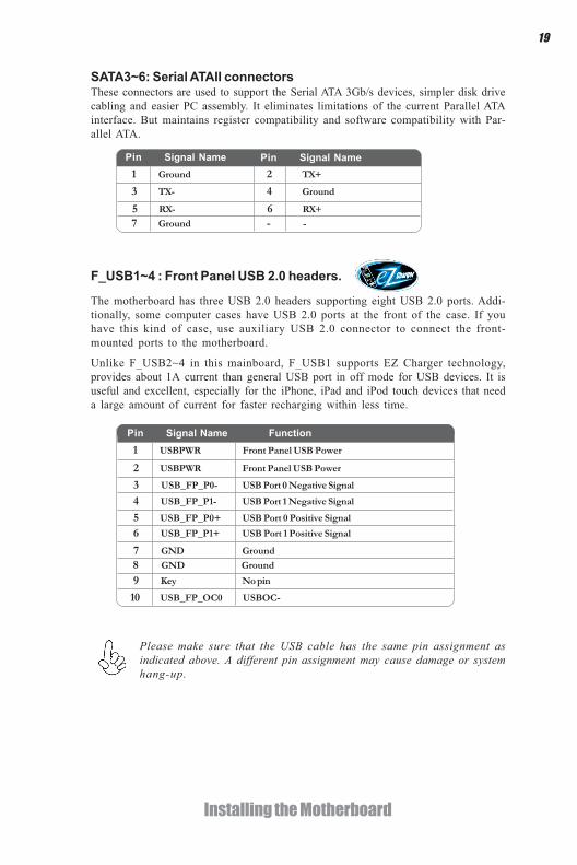
F_USB1~4 : Front Panel USB 2.0 headers.
SATA3~6: Serial ATAII connectorsThese connectors are used to support the Serial ATA 3Gb/s devices, simpler disk drivecabling and easier PC assembly. It eliminates limitations of the current Parallel ATAinterface. But maintains register compatibility and software compatibility with Par-allel ATA.
1 Ground 2 TX+
3 TX- 4 Ground
5 RX- 6 RX+
7 Ground - -
Pin Signal NamePin Signal Name
Unlike F_USB2~4 in this mainboard, F_USB1 supports EZ Charger technology,provides about 1A current than general USB port in off mode for USB devices. It isuseful and excellent, especially for the iPhone, iPad and iPod touch devices that needa large amount of current for faster recharging within less time.
Please make sure that the USB cable has the same pin assignment asindicated above. A different pin assignment may cause damage or systemhang-up.
1 USBPWR Front Panel USB Power
2 USBPWR Front Panel USB Power
3 USB_FP_P0- USB Port 0 Negative Signal
4 USB_FP_P1- USB Port 1 Negative Signal
5 USB_FP_P0+ USB Port 0 Positive Signal
6 USB_FP_P1+ USB Port 1 Positive Signal
7 GND Ground
8 GND Ground
9 Key No pin
10 USB_FP_OC0 USBOC-
Pin Signal Name Function
The motherboard has three USB 2.0 headers supporting eight USB 2.0 ports. Addi-tionally, some computer cases have USB 2.0 ports at the front of the case. If youhave this kind of case, use auxiliary USB 2.0 connector to connect the front-mounted ports to the motherboard.

20
Installing the Motherboard
CASE: Chassis Intrusion Detect HeaderThis detects if the chassis cover has been removed. This function needs a chassisequipped with instrusion detection switch and needs to be enabled in BIOS.
This is a header that can be used to connect to the printer, scanner or other devices.
LPT: Onboard parallel port header
1 STB 14 AFD
2 PD0 15 ERR
3 PD1 16 PRNINIT
4 PD2 17 SLIN
5 PD3 18 GND
6 PD4 19 GND1
7 PD5 20 GND2
Pin Signal Name Pin Signal Name
8 PD6 21 GND3
9 PD7 22 GND4
10 ACK 23 GND5
11 BUSY 24 GND6
12 PE 25 GND7
13 SLCT 26 Key
Connect a serial port extension bracket to this header to add a serial port to yoursystem.
COM: Onboard serial port header
Short Chassis cover is removed
Open Chassis cover is closed
Pin 1-2 Function
Pin Signal Name Pin Signal Name
1 DCD 2 RX
3 TX 4 DTR
5 Ground 6 OSR
7 RTS 8 CTS
9 RL 10 Key

21
Installing the Motherboard
This 16 MB DEBUG contains the programmable BIOS program.
SPI_DEBUG: SPI Debug header
1 CHIPSELECT Select chip
2 VCC VCC
3 DATA OUTPUT data output
4 HOLD hold
5 WRITE PROTECT BIOS write protect
6 CLOCK clock
7 GND Ground
8 DATA INPUT data input
Pin Signal Name Function
ME_UNLOCK: ME Unlock Header
SPDIFO: SPDIF out headerThis is an optional header that provides an SPDIFO (Sony/Philips Digital Interface)output to digital multimedia device through optical fiber or coaxial connector.
Short Unlock
Open Lock
Pin 1-2 Function
1 SPDIFOUT
2 +5V
3 Key
4 GND
Pin Signal Name

22
Installing the Motherboard
Installing SATA Hard DrivesThis section describes how to install SATA devices such as a hard disk drive and a CD-ROM drive.
SATA cable (optional) SATA power cable (optional)
About SATA ConnectorsYour motherboard features four SATA 3.0 Gb/s connectors and four SATA 6.0Gb/sconnectors supporting a total of eight drives SATA refers to Serial ATA (AdvancedTechnology Attachment) is the standard interface for the SATA hard drives whichare currently used in most PCs. These connectors are well designed and will only fitin one orientation. Locate the SATA connectors on the motherboard and follow theillustration below to install the SATA hard drives.
Installing Serial ATA Hard DrivesTo install the Serial ATA (SATA) hard drives, use the SATA cable that supports theSerial ATA protocol. You can connect either end of the SATA cable to the SATA harddrive or the connector on the motherboard.
Refer to the illustration below for proper installation:
This motherboard supports the “Hot-Plug” function.
1 Attach either cable end to the connector on the motherboard.2 Attach the other cable end to the SATA hard drive.3 Attach the SATA power cable to the SATA hard drive and connect the
other end to the power supply.
* For reference only

23
Installing the Motherboard
Connecting I/O DevicesThe backplane of the motherboard has the following I/O ports:
VGA Port Connect the VGA port to the monitor.
PS/2 Keyboard Port
LAN Ports
USB 2.0 Ports
Connect an RJ-45 jack to the LAN port to connect yourcomputer to the Network.
Use the USB 2.0 ports to connect USB 2.0 devices.
USB 3.0 Ports Use the USB 3.0 ports to connect USB 3.0 devices.
PS/2 Mouse Port
Use the upper PS/2 port to connect a PS/2 pointingdevice.
Use the lower PS/2 port to connect a PS/2 keyboard.
DVI Port Connect the DVI port (or HDMI port) to the monitor.
Audio Ports Use the audio jacks to connect audio devices. The C portis for stereo line-in signal, while the E port is for micro-phone in signal. This motherboard supports audio de-vices that correspond to the A, B, and D port respec-tively. In addition, both of the 2 ports, B, and D provideusers with both right & left channels individually. Usersplease refer to the following note for specific port func-tion definition.
The above port definition can be changed to audio inputor audio output by changing the driver utility setting.
A: Center & Woofer D: Front Out B: Back Surround E: M ic_in Rear C: Line-in -
Optical SPDIF Output This jack connects to external optical digital audio out-put devices.
USB3.0 optional & compatible with USB 2.0.
(HDMI Port Optional)

24
Installing the Motherboard
Connecting Case ComponentsAfter you have installed the motherboard into a case, you can begin connecting themotherboard components. Refer to the following:
1 Connect the CPU cooling fan cable to CPU_FAN.2 Connect the system cooling fan connector to SYS_FAN.3 Connect the case speaker cable to SPK.4 Connect the case switches and indicator LEDs to the F_PANEL.5 Connect the standard power supply connector to ATX_POWER.6 Connect the auxiliary case power supply connector to ATX12V.
The ATX 24-pin connector allows you to connect to ATX v2.x power supply.
With ATX v2.x power supply, users please notethat when installing 24-pin power cable, thelatches of power cable and the ATX_POWERmatch perfectly.
1. Connecting 24-pin power cable
24-pin power cable

25
Installing the Motherboard
Users please note that the fan connector supports the CPU cooling fan of1.1A ~ 2.2A (26.4W max) at +12V.
CPU_FAN: CPU cooling FAN Power Connector
The ATX12V power connector is used to provide power to the CPU.2. Connecting 4 power cable
SYS_FAN: System cooling FAN Power Connector
1 GND System Ground
3 Sense Sensor
4 CONTROL CONTROL
Pin Signal Name Function
2 +12V Power +12V
ATX_ POWER: ATX 24-pin Power Connector
Pin Signal Name Pin Signal Name1 +3.3V 13 +3.3V
2 +3.3V 14 -12V
3 Ground 15 Ground
4 +5V 16 PS_ON
5 Ground 17 Ground
6 +5V 18 Ground
7 Ground 19 Ground
8 PWRGD 20 -5V
9 +5VSB 21 +5V
10 +12V 22 +5V
11 +12V 23 +5V
12 +3.3V 24 Ground
1 GND System Ground
3 Sense Sensor
Pin Signal Name Function
2 +12V Power +12V
When installing 4-pin power cable, the latchesof power cable and the ATX12V match per-fectly.
4-pin power cable

26
Installing the Motherboard
SPK: External Speaker header
ATX12V: ATX 12V Power Connector
Pin Signal Name
4 +12V
3 +12V
2 Ground
1 Ground
1 VCC
2 Key
3 GND
4 Signal
Pin Signal Name

27
Installing the Motherboard
Hard Drive Activity LEDConnecting pins 1 and 3 to a front panel mounted LED provides visual indicationthat data is being read from or written to the hard drive. For the LED to functionproperly, an IDE drive should be connected to the onboard IDE interface. The LEDwill also show activity for devices connected to the SCSI (hard drive activity LED)connector.
Power/Sleep/Message waiting LEDConnecting pins 2 and 4 to a single or dual-color, front panel mounted LED providespower on/off, sleep, and message waiting indication.
Reset SwitchSupporting the reset function requires connecting pin 5 and 7 to a momentary-contact switch that is normally open. When the switch is closed, the board resets andruns POST.
Power SwitchSupporting the power on/off function requires connecting pins 6 and 8 to a momen-tary-contact switch that is normally open. The switch should maintain contact for atleast 50 ms to signal the power supply to switch on or off. The time requirement isdue to internal de-bounce circuitry. After receiving a power on/off signal, at least twoseconds elapses before the power supply recognizes another on/off signal.
This concludes Chapter 2. The next chapter covers the BIOS.
Front Panel HeaderThe panel header (PANEL) provides a standard set of switch and LED headerscommonly found on ATX or Micro ATX cases. Refer to the table below for informa-tion:
Pin Signal Function Pin Signal Function1 HD_LED_P Hard disk LED(+) 2 FP PWR/SLP *MSG LED(+)
3 HD_LED_N Hard disk LED(- )
5 RST_SW_N Reset Switch(-)7 RST_SW_P Reset Switch(+)
9 RSVD Reserved
4 FP PWR/SLP *MSG LED(-)6 PWR_SW_P Power Switch(+)
8 PWR_SW_N Power Switch(-)
10 Key No pin
* MSG LED (dual color or single color)
Users please note that the above picture is for reference only, you shoulddetermine the header pin definition by the actual key pin location.

28
Installing the Motherboard
Memo

29
Using BIOS
About the Setup UtilityThe computer uses the latest “American Megatrends Inc. ” BIOS with support forWindows Plug and Play. The CMOS chip on the motherboard contains the ROMsetup instructions for configuring the motherboard BIOS.
The BIOS (Basic Input and Output System) Setup Utility displays the system’sconfiguration status and provides you with options to set system parameters. Theparameters are stored in battery-backed-up CMOS RAM that saves this informationwhen the power is turned off. When the system is turned back on, the system isconfigured with the values you stored in CMOS.
The BIOS Setup Utility enables you to configure:
• Hard drives, diskette drives and peripherals• Video display type and display options• Password protection from unauthorized use• Power Management features
The settings made in the Setup Utility affect how the computer performs. Beforeusing the Setup Utility, ensure that you understand the Setup Utility options.
This chapter provides explanations for Setup Utility options.
The Standard ConfigurationA standard configuration has already been set in the Setup Utility. However, werecommend that you read this chapter in case you need to make any changes in thefuture.
This Setup Utility should be used:• when changing the system configuration• when a configuration error is detected and you are prompted to make
changes to the Setup Utility• when trying to resolve IRQ conflicts• when making changes to the Power Management configuration• when changing the password or making other changes to the Security
Setup
Entering the Setup UtilityWhen you power on the system, BIOS enters the Power-On Self Test (POST)routines. POST is a series of built-in diagnostics performed by the BIOS. After thePOST routines are completed, the following message appears:
Press DEL to enter SETUP
Chapter 3
Using BIOS

30
Using BIOS
Press the delete key to access BIOS Setup Utility.
Using BIOSWhen you start the Setup Utility, the main menu appears. The main menu of theSetup Utility displays a list of the options that are available. A highlight indicateswhich option is currently selected. Use the cursor arrow keys to move the highlightto other options. When an option is highlighted, execute the option by pressing<Enter>.
Some options lead to pop-up dialog boxes that prompt you to verify that you wish toexecute that option. Other options lead to dialog boxes that prompt you for infor-mation.
Some options (marked with a triangle ) lead to submenus that enable you to changethe values for the option. Use the cursor arrow keys to scroll through the items in thesubmenu.
Resetting the Default CMOS ValuesWhen powering on for the first time, the POST screen may show a “CMOSSettings Wrong” message. This standard message will appear following a clearCMOS data at factory by the manufacturer. You simply need to Load DefaultSettings to reset the default CMOS values.
Note: Changes to system hardware such as different CPU, memories, etc. may alsotrigger this message.
BIOS Information
System Language [English]
System Date [ Mon 09/10/2012]System Time [21:54:45]
Choose the system defaultlanguage.
Aptio Setup Utility - Copyright (C) 2012 American Megatrends, Inc.
Version 2.15.1229. Copyright (C) 2012, American Megatrends, Inc.
Main Advanced Chipset M.I.B III Boot Security Exit
F1:General Help+/- : Change Opt.Enter : Select
:Select Screen:Select Item
F2:Previous Values F3:Optimized Defaults F4:Save & Exit ESC:Exit

31
Using BIOS
The default BIOS setting for this motherboard apply for most conditionswith optimum performance. We do not suggest users change the defaultvalues in the BIOS setup and take no responsibility to any damagecaused by changing the BIOS settings.
BIOS Navigation KeysThe BIOS navigation keys are listed below:
KEY FUNCTION
Scrolls through the items on a menu
+/- Modifies the selected field’s values
F2 Previous Value
F3 Optimized Defaults
F1 General Help
ESC Exits the current menu
Enter Select
In this manual, default values are enclosed in parenthesis. Submenu items are denotedby a triangle .
F4 Save & Exit
For the purpose of better product maintenance, the manufacture reservesthe right to change the BIOS items presented in this manual. The BIOSsetup screens shown in this chapter are for reference only and may differfrom the actual BIOS. Please visit the manufacture’s website for updatedmanual.

32
Using BIOS
System Date & TimeThe Date and Time items show the current date and time on the computer. If you arerunning a Windows OS, these items are automatically updated whenever you makechanges to the Windows Date and Time Properties utility.
When you enter the BIOS Setup program, the main menu appears, giving you anoverview of the basic system information. Select an item and press <Enter> todisplay the submenu.
Main Menu
BIOS Information
System Language [English]
System Date [ Mon 09/10/2012]System Time [21:54:45]
Choose the system defaultlanguage.
Aptio Setup Utility - Copyright (C) 2012 American Megatrends, Inc.
Version 2.15.1229. Copyright (C) 2012, American Megatrends, Inc.
Main Advanced Chipset M.I.B III Boot Security Exit
F1:General Help+/- : Change Opt.Enter : Select
:Select Screen:Select Item
F2:Previous Values F3:Optimized Defaults F4:Save & Exit ESC:Exit
System Language (English)This item is used to set system language.

33
Using BIOS
The Advanced menu items allow you to change the settings for the CPU and othersystem.
Advanced Menu
Onboard LAN Controller (Enabled)Use this item to enable or disable the Onboard LAN.
Press <Esc> to return to the Advanced Menu page.
LAN ConfigurationThe item in the menu shows the LAN-related information that the BIOSautomatically detects.
Enable/Disable Onboard LANController
Aptio Setup Utility - Copyright (C) 2012 American Megatrends, Inc.
Version 2.02.1205. Copyright (C) 2010, American Megatrends, Inc.
LAN Configuration PC Health Status Power Management Setup ACPI Settings CPU Configuration SATA Configuration USB Configuration Super IO Configuration Intel(R) Smart Connect Technology
LAN Configuration Parameters
Aptio Setup Utility - Copyright (C) 2012 American Megatrends, Inc.
F1:General Help+/- : Change Opt.Enter : Select
:Select Screen:Select Item
F2:Previous Values F3:Optimized Defaults F4:Save & Exit ESC:Exit
F1:General Help+/- : Change Opt.Enter : Select
:Select Screen:Select Item
F2:Previous Values F3:Optimized Defaults F4:Save & Exit ESC:Exit
Version 2.15.1229. Copyright (C) 2012, American Megatrends, Inc.
Main Advanced Chipset M.I.B III Boot Security Exit
Version 2.15.1229. Copyright (C) 2012, American Megatrends, Inc.
Main Advanced Chipset M.I.B III Boot Security Exit
LAN Configuration
Onboard LAN Controller [Enabled]
Network Stack [Enabled]Ipv4 PXE Support [Enabled]Ipv6 PXE Support [Enabled]
Network stack (Enabled)Use this item to enable or disable UEFI network stack.Ipv4/6 PXE Support (Enabled)Use these items to enable Ipv4/6 PXE Boot Support. If disabled Ipv4/6 PXE, bootoption will not be created.
34
Using BIOS
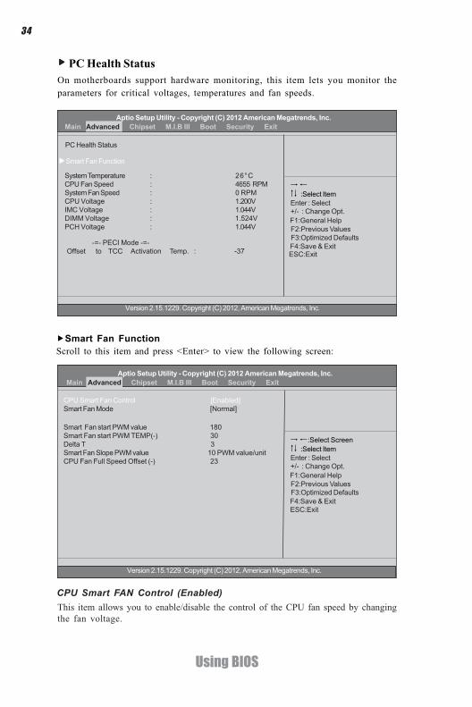
PC Health StatusOn motherboards support hardware monitoring, this item lets you monitor theparameters for critical voltages, temperatures and fan speeds.
-=- PECI Mode -=-Offset to TCC Activation Temp : -27
+/- : Change Opt.Enter : Select
:Select Item
F1:General Help F2:Previous Values F3:Optimized Defaults F4:Save & Exit
System Temperature : 26°CCPU Fan Speed : 4655 RPMSystem Fan Speed : 0 RPMCPU Voltage : 1.200VIMC Voltage : 1.044VDIMM Voltage : 1.524VPCH Voltage : 1.044V
Smart Fan Function
ESC:Exit -=- PECI Mode -=-Offset to TCC Activation Temp. : -37
CPU Smart FAN Control (Enabled)This item allows you to enable/disable the control of the CPU fan speed by changingthe fan voltage.
Version 2.02.1205. Copyright (C) 2012, American Megatrends, Inc.Scroll to this item and press <Enter> to view the following screen:Smart Fan Function
Aptio Setup Utility - Copyright (C) 2010 American Megatrends, Inc.
+/- : Change Opt.Enter : Select
:Select Screen:Select Item
F1:General Help F2:Previous Values F3:Optimized Defaults F4:Save & Exit ESC:Exit
CPU Smart Fan Control [Enabled]Smart Fan Mode [Normal]
Smart Fan start PWM value 180Smart Fan start PWM TEMP(-) 30Delta T 3Smart Fan Slope PWM value 10 PWM value/unitCPU Fan Full Speed Offset (-) 23
PC Health Status
Aptio Setup Utility - Copyright (C) 2012 American Megatrends, Inc.
Version 2.15.1229. Copyright (C) 2012, American Megatrends, Inc.
Main Advanced Chipset M.I.B III Boot Security Exit
Aptio Setup Utility - Copyright (C) 2012 American Megatrends, Inc.
Version 2.15.1229. Copyright (C) 2012, American Megatrends, Inc.
Main Advanced Chipset M.I.B III Boot Security Exit

35
Using BIOS
Smart Fan start PWM value (180)
Smart Fan start PWM TEMP(-) (30)This item is used to set the start PWM value of the smart fan.
This item is used to set the start temperature of the smart fan.
DeltaT (3)This item specifies the range that controls CPU temperature and keeps it from goingso high or so low when smart fan works.
Smart Fan Slope PWM value (10 PWM value/unit)This item is used to set the Slope Select PWM of the smart fan.
This item is used to set the CPU fan full speed offset value.CPU Fan Full Speed Offset(-) (23)
Smart Fan Mode (Normal)This item allows you to select the fan mode (Normal, Quiet, Silent, or Manual) for abetter operation environment. If you choose Normal mode, the fan speed will be autoadjusted depending on the CPU temperature. If you choose Quiet mode, the fan speedwill be auto minimized for quiet environment. If you choose Silent mode, the fanspeed will be auto restricted to make system more quietly. If you choose Manualmode, the fan speed will be adjust depending on users’ parameters.
Press <Esc> to return to the PC Health Status page.
• System Temperature • CPU Fan Speed • System Fan Speed • CPU Voltage • IMC Voltage • DIMM Voltage • PCH Voltage
System Component CharacteristicsThese items display the monitoring of the overall inboard hardware health events,such as System temperature, CPU & DIMM voltage, CPU & system fan speed...etc.
Press <Esc> to return to the Advanced Menu page.

36
Using BIOS
+/- : Change Opt.Enter : Select
:Select Screen:Select Item
Power Management Setup
Resume by RING [Disabled]Resume By PME [Disabled]Resume By USB (S3) [Disabled]Resume By PS2 KB (S3) [Disabled]Resume By PS2 MS (S3) [Disabled]EUP Function [Enabled]Power LED Type [Dual Color LED]
F1:General Help F2:Previous Values F3:Optimized Defaults F4:Save & Exit ESC:Exit
About Resume by Ring
Power Management SetupThis page sets up some parameters for system power management operation.
Resume by Ring (Disabled)An input signal on the serial Ring Indicator (RI) line (in other words, an incoming callon the modem) awakens the system from a soft off state.
Resume By PME (Disabled)The system can be turned off with a software command. If you enable this item, thesystem can automatically resume if there is an incoming call on the PCI Modem orPCI LAN card. You must use an ATX power supply in order to use this feature. Usethis item to do wake-up action if inserting the PCI card.
Resume By USB (S3) (Disabled)This item allows you to enable/disable the USB device wakeup function from S3mode.
Resume By PS2 KB (S3) (Disabled)This item enables or disables you to allow keyboard activity to awaken the systemfrom power saving mode.Resume By PS2 MS (S3) (Disabled)This item enables or disables you to allow mouse activity to awaken the system frompower saving mode.
EUP Support (Enabled)This item allows user to enable or disable EUP support.
Power LED Type (Dual Color LED)This item allows user to enable or disable EUP support.
Press <Esc> to return to the Advanced Menu page.
Aptio Setup Utility - Copyright (C) 2012 American Megatrends, Inc.
Version 2.15.1229. Copyright (C) 2012, American Megatrends, Inc.
Main Advanced Chipset M.I.B III Boot Security Exit

37
Using BIOS
ACPI ConfigurationThe item in the menu shows the highest ACPI sleep state when the system enterssuspend.
ACPI Sleep State (S3(Suspend to RAM))This item allows user to enter the ACPI S3 (Suspend toRAM) Sleep State (default).
Press <Esc> to return to the Advanced Menu page.
+/- : Change Opt.Enter : Select
:Select Screen:Select Item
ACPI Settings
ACPI Sleep State [S3 (Suspend to RAM)]
F1:General Help F2:Previous Values F3:Optimized Defaults F4:Save & Exit ESC:Exit
Select the highest ACPI sleepstate the system will enterwhen the SUSPEND button ispressed.
Aptio Setup Utility - Copyright (C) 2012 American Megatrends, Inc.
Version 2.15.1229. Copyright (C) 2012, American Megatrends, Inc.
Main Advanced Chipset M.I.B III Boot Security Exit

38
Using BIOS
CPU ConfigurationThe item in the menu shows the CPU .
CPU Configuration
Inter(R) Pentium(R) CPU G860 @ 3.00 GHzEM64T SupportedProcessor Speed 3000 MHzProcessor Stepping 206a7Microcode Revision 25Processor Cores 2Intel HT Technology Not SupportedIntel VT-x Technology Supported
Active Processor Cores [All]Limit CPUID Maximum [Disabled]Execute Disable Bit [Enabled]Intel Virtualization Technology [Enabled]CPU C3 Report [Disabled]CPU C6 Report [Enabled]Enhanced Halt (C1E) [Enabled]
+/- : Change Opt.
:Select Screen:Select Item
F1:General Help F2:Previous Values F3:Optimized Defaults F4:Save & Exit ESC:Exit
Enter : Select
Number of Cores to enable ineach processor package.
Inter(R) Pentium(R) CPU G860 @ 3.00 GHzThis is display-only field and diaplays the information of the CPU installed in yourcomputer.
EM64T (Supported)This item shows the computer supports EM64T.
Processor Speed (3000MHz)This item shows the processor speed.
Processor Stepping (206a7)This item shows the information of processor stepping.
Microcode Revision (25)This item shows the Microcode revision.
Processor Cores (2)This item shows the information of the processor cores.
Intel HT Technology (Not Supported)This item shows your computer does not support Intel HT technology.
Intel VT-x Technology (Supported)This item shows your computer support Intel VT-x technology.
Aptio Setup Utility - Copyright (C) 2012 American Megatrends, Inc.
Version 2.15.1229. Copyright (C) 2012, American Megatrends, Inc.
Main Advanced Chipset M.I.B III Boot Security Exit

39
Using BIOS
Excute Disable Bit (Enabled)This item allows the processor to classify areas in memory by where application codecan execute and where it cannot. When a malicious worm attempts to insert code inthe buffer, the processor disables code execution, preventing damage or worm propa-gation. Replacing older computers with Execute Disable Bit enabled systems can haltworm attacks, reducing the need for virus related repair.
Intel Virtualization Technology (Enabled)When enabled, a VMM can utilize the additional hardware capabilities provided byVandor Pool Technology.
CPU C3 Report (Disabled)Use this item to enable or disable CPU C3(ACPI C2) report to OS.
Press <Esc> to return to the Advanced Menu page.
Limit CPUID Maximum (Disabled)Use this item to enable or disable the maximum CPUID value limit. When supportsPrescott and LGA775 CPUs, enables this to prevent the system from “rebooting”when trying to install Windows NT 4.0.
CPU C6 Report (Enabled)Use this item to enable or disable CPU C6(ACPI C3) report to OS.
Enhanced Halt (C1E) (Enabled)Use this item to enable the CPU energy-saving function when the system is notrunning.

40
Using BIOS
SATA ConfigurationUse this item to show the mode of serial SATA configuration options.
SATA Configuration
SATA Mode [IDE Mode]
SATA Port1 Not Present
SATA Port2 Not Present
SATA Port3 Not Present
SATA Port4 Not Present
SATA Port5 Not Present
SATA Port6 Not Present
+/- : Change Opt.
:Select Screen:Select Item
F1:General Help F2:Previous Values F3:Optimized Defaults F4:Save & Exit ESC:Exit
Enter : Select
Determines how SATAcontroller(s) operate.
SATA Mode (IDE Mode)Use this item to select SATA mode.
SATA Port1~6This motherboard supports six SATA channel and each channel allows one SATAdevice to be installed. Use these items to configure each device on the SATA channel.
Press <Esc> to return to the Advanced Menu page.
Aptio Setup Utility - Copyright (C) 2012 American Megatrends, Inc.
Version 2.15.1229. Copyright (C) 2012, American Megatrends, Inc.
Main Advanced Chipset M.I.B III Boot Security Exit

41
Using BIOS
All USB Devices (Enabled)Use this item to enable or disable all USB devices.
USB ConfigurationUse this item to show the information of USB configuration.
+/- : Change Opt.Enter : Select
:Select Screen:Select Item
USB Configuration
All USB Devices [Enabled]
OnChip USB 3.0 Controller [Enabled]
F1:General Help F2:Previous Values F3:Optimized Defaults F4:Save & Exit ESC:Exit
USB Support Parameters
Legacy USB Support [Enabled]
OnChip USB 3.0 Controller (Enabled)Use this item to enable or disable USB 3.0 controller. We recommend users keep thedefault value. Disabling it might cause the USB devices not to work properly.
Legacy USB Support (Enabled)Use this item to enable or disable support for legacy USB devices.
Press <Esc> to return to the Advanced Menu page.
Aptio Setup Utility - Copyright (C) 2012 American Megatrends, Inc.
Version 2.15.1229. Copyright (C) 2012, American Megatrends, Inc.
Main Advanced Chipset M.I.B III Boot Security Exit

42
Using BIOS
Super IO ConfigurationUse this item to show the information of Super IO configuration.
+/- : Change Opt.Enter : Select
:Select Screen:Select Item
Super IO Configuration
Super IO Chip IT8728Serial Port 0 ConfigurationParallel Port Configuration
F1:General Help F2:Previous Values F3:Optimized Defaults F4:Save & Exit ESC:Exit
Set Parameters of Serial Port0 (COMA)
Serial Port 0 ConfigurationScroll to this item and press <Enter> and view the following screen.
Serial Port (Enabled)This item allows you to enable or disable serial port.Device Settings (IO=3F8h; IRQ=4)This item shows the information of the device settings.
Change Settings (Auto)Use this item to change device settings.
Press <Esc> to return to the Super IO Configuration page.
+/- : Change Opt.Enter : Select
:Select Screen:Select Item
Serial Port 0 Configuration
Serial Port [Enabled]Device Settings IO=3F8h; IRQ=4;
Change Settings [Auto]
F1:General Help F2:Previous Values F3:Optimized Defaults F4:Save & Exit ESC:Exit
Enable or Disable Serial Port(COM)
Aptio Setup Utility - Copyright (C) 2012 American Megatrends, Inc.
Version 2.15.1229. Copyright (C) 2012, American Megatrends, Inc.
Main Advanced Chipset M.I.B III Boot Security Exit
Aptio Setup Utility - Copyright (C) 2012 American Megatrends, Inc.
Version 2.15.1229. Copyright (C) 2012, American Megatrends, Inc.
Main Advanced Chipset M.I.B III Boot Security Exit

43
Using BIOS
Parallel Port ConfigurationScroll to this item and press <Enter> and view the following screen.
Parallel Port (Enabled)This item allows you to enable or disable serial port.Device Settings (IO=378h; IRQ=5)This item shows the information of the device settings.
Change Settings (Auto)Use this item to change device settings.
+/- : Change Opt.Enter : Select
:Select Screen:Select Item
Parallel Port Configuration
Parallel Port [Enabled]Device Settings IO=378h; IRQ=5;
Change Settings [Auto]Device Mode [Standard Parallel ... ]
F1:General Help F2:Previous Values F3:Optimized Defaults F4:Save & Exit ESC:Exit
Enable or Disable ParallelPort (LPT/LPTE)
Device Mode (Standard Parallel... )This item allows you to select the device mode for a better operation environment.
Press <Esc> to return to the Super IO Configuration page.
Aptio Setup Utility - Copyright (C) 2012 American Megatrends, Inc.
Version 2.15.1229. Copyright (C) 2012, American Megatrends, Inc.
Main Advanced Chipset M.I.B III Boot Security Exit

44
Using BIOS
Intel(R) Smart Connect TechnologyUse this item to show the information of Intel(R) Smart Connect Technology.
Aptio Setup Utility - Copyright (C) 2012 American Megatrends, Inc.
F1:General Help+/- : Change Opt.Enter : Select
:Select Screen:Select Item
F2:Previous Values F3:Optimized Defaults F4:Save & Exit ESC:Exit
Version 2.15.1229. Copyright (C) 2012, American Megatrends, Inc.
Main Advanced Chipset M.I.B III Boot Security Exit
ISCT Configuration [Enabled]
ISCT Notification Control [Enabled]ISCT WLAN Power Control [Enabled]ISCT WWAN Power Control [Enabled]ISCT Sleep Duration Value Format [Actual Time]
Enabled/Disabled ISCT Configura-tion
ISCT Configuration (Enabled)Use this item to enable/disable ISCT Configuration.
ISCT Notification Control (Enabled)Use this item to enable/disable ISCT Notification Control.
ISCT WLAN Power Control (Enabled)Use this item to enable/disable ISCT WLAN Power Control.
ISCT WWAN Power Control (Enabled)Use this item to enable/disable ISCT WWAN Power Control.
ISCT Sleep Duration Value Format (Actual Time)Use this item to select actual time or duration in seconds. (ISCT 2.0)

45
Using BIOS
The chipset menu items allow you to change the settings for the North chipset,South chipset and other system.
Chipset Menu
System Agent ConfigurationScroll to this item and press <Enter> and view the following screen.
Initate Graphic Adapter (Auto)This item allows you to select graphics controller to use as the primary boot device.
+/- : Change Opt.Enter : Select
:Select Screen:Select Item
F1:General Help F2:Previous Values F3:Optimized Defaults F4:Save & Exit ESC:Exit
System Agent (SA) ParametersSystem Agent ConfigurationPCH ConfigurationME Configuration
+/- : Change Opt.Enter : Select
:Select Screen:Select Item
F1:General Help F2:Previous Values F3:Optimized Defaults F4:Save & Exit ESC:Exit
Select which of IGFX/PEG/PCIGraphics device should be PrimaryDisplay or select SG for SwitchableGfx.
System Agent Configuration
Initate Graphic Adapter [Auto]IGD Memory [64M]DVMT Memory [256M]IGD Multi-Monitor [Disabled]
IGD Memory (64M)This item shows the information of the IGD(Internal Graphics device) memory.
DVMT Memory (256M)When set to Fixed Mode, the graphics driver will reserve a fixed position of thesystem memory as graphics memory, according to system and graphics requirements.
IGD Multi-Monitor (Disabled)This item enables or disables IGD(Internal Graphics device) multi-monitor.
Aptio Setup Utility - Copyright (C) 2012 American Megatrends, Inc.
Version 2.15.1229. Copyright (C) 2012, American Megatrends, Inc.
Main Advanced Chipset M.I.B III Boot Security Exit
Aptio Setup Utility - Copyright (C) 2012 American Megatrends, Inc.
Version 2.15.1229. Copyright (C) 2012, American Megatrends, Inc.
Main Advanced Chipset M.I.B III Boot Security Exit

46
Using BIOS
Press <Esc> to return to the chipset menu page.
Multi-Monitor technology
Please note that Multi-Monitor technology supports up to four monitors:one or two Intel integrated Graphics and one or two PCI-Express graphicsdevices under Windows 7/8.
Multi-Monitor technology can help you to increase the area available for programsrunning on a single computer system through using multiple display devices.It is not only to increase larger screen viewing but aslo to improving personalproductivity.
Step 1. Insert ECS drives DVD to run Auto setup or browse the DVD to install Intelchipset drivers, VGA and sound drivers.(If you want know the detail information,please refer to chapter 4.)
Intel Integrated Graphics PCI-Express Graphics
The DVD versionis for referenceonly.

47
Using BIOS
+/- : ValueEnter : Select
:Select Screen:Select Item
F1:General Help F2:Previous Value F3:Optimized Defaults F4:Save & Exit ESC:Exit
System Agent Configuration
Initate Graphic Adapter [Auto]IGD Memory [64M]DVM Memory [256MB]IGD Multi-Monitor [Disabled]
Step 3. Enable IGD Multi-Monitor from BIOS. In the following BIOS screen, pleaseset IGD Multi-Monitor to [Enabled].
Step 2. Install all the drivers of PCI-Express graphic cards. Click the Browse CDitem, then appears the following screen. Select the driver you want to install(e.gNVIDIA GeForce 8400 GS(Microsoft Corporation-WDDM v1.1)) and double clickit.
Select which of IGFX/PEG/PCIGraphics device should be PrimaryDisplay or select SG for SwitchableGfx.
Aptio Setup Utility - Copyright (C) 2012 American Megatrends, Inc.
Version 2.15.1229. Copyright (C) 2012, American Megatrends, Inc.
Main Advanced Chipset M.I.B III Boot Security Exit

48
Using BIOS
2.Select display devices, set the multiple displays option and to extend destop fordisplay “Multi-Monitor technology”.
Change the apprearance of your displays
Control Panel All Control Panel Items Display Screen Resolution Search Control Panel
13 4 Detect
Identify
3. DELL U2410Display:
Resolution: 1920 x 1200 (recommended)
Orientation: Landscape
Disconnect this displayMultiple displays:
Make this my main display Advance settingsMake text and other items larger or smallerWhat display settings should I choose?
OK Cancel Apply
2
You must select Apply before making additional changes.!Extend desktop to this displayDisconnect this display
Step 4. Change the appearance of your displays under Windows 7/8.
Change the apprearance of your displays
Control Panel All Control Panel Items Display Screen Resolution Search Control Panel
12 3 4 Detect
Identify
1. DELL U2410Display:
Resolution: 1920 x 1200 (recommended)
Orientation: Landscape
Extend desktop to this displayMultiple displays:
This is currently your main display. Advance settingsMake text and other items larger or smallerWhat display settings should I choose?
OK Cancel Apply
Show the path of the setting location
Display devices
The type of the display
Set the multiple displays
1. Enter the Control Panel menu, select the Display in the All Control Panel Itemsand click the Screen Resolution, then appears the following screen.

49
Using BIOS
Change the apprearance of your displays
Control Panel All Control Panel Items Display Screen Resolution Search Control Panel
1 Detect
Identify
4. AL1717Display:
Resolution: 1920 x 1200 (recommended)
Orientation: Landscape
Disconnect this displayMultiple displays:
Make this my main display Advance settingsMake text and other items larger or smallerWhat display settings should I choose?
OK Cancel Apply
2
You must select Apply before making additional changes.!
3 4
3
Change the apprearance of your displays
Control Panel All Control Panel Items Display Screen Resolution Search Control Panel
1 Detect
Identify
4. AL1717Display:
Resolution: 1920 x 1200 (recommended)
Orientation: Landscape
Extend desktop to this displayMultiple displays:
Make this my main display Advance settingsMake text and other items larger or smallerWhat display settings should I choose?
OK Cancel Apply
2
You must select Apply before making additional changes.!
3 4

50
Using BIOS
PCH ConfigurationScroll to this item and press <Enter> to view the following screen.
+/- : Change Opt.Enter : Select
:Select Screen:Select Item
F1:General Help F2:Previous Values F3:Optimized Defaults F4:Save & Exit ESC:Exit
Select AC power state whenpower is re-applied after apower failure
PCH Configuration
Restore AC Power Loss [Power Off]
Audio ConfigurationAzalia HD Audio [Enabled]Azalia internal HDMI codec [Enabled]
Case Open Warning [Disabled]Chassis Opened [No]
Restore AC Power Loss (Power Off)This item specifies what state to go to when power is re-applied after a power failure(G3 state).Audio ConfigurationThis item shows the information of the audio configuration.
Azalia HD Audio (Enabled)This item enables or disables Azalia HD audio.
Press <Esc> to return to the chipset menu page.
Case Open Warning (Disabled)This item enables or disables the warning if the case is opened up, and the item belowindicates the current status of the case.
Chassis Opened (No)This item indicates whether the case has been opened.
Azalia internal HDMI Codec (Enabled)This item enables or disables Azalia internal HDMI codec.
Aptio Setup Utility - Copyright (C) 2012 American Megatrends, Inc.
Version 2.15.1229. Copyright (C) 2012, American Megatrends, Inc.
Main Advanced Chipset M.I.B III Boot Security Exit

51
Using BIOS
Azalia HD Audio
EnabledDisabled
+/- : Change Opt.Enter : Select
:Select Screen:Select Item
F1:General Help F2:Previous Values F3:Optimized Defaults F4:Save & Exit ESC:Exit
Management Engine Technology Configuration
ME Version 8.1.0.1248
ME ConfigurationScroll to this item and press <Enter> to view the following screen.
ME Version (8.1.0.1248)This item shows the ME version.
Press <Esc> to return to the chipset menu page.
Aptio Setup Utility - Copyright (C) 2012 American Megatrends, Inc.
Version 2.15.1229. Copyright (C) 2012, American Megatrends, Inc.
Main Advanced Chipset M.I.B III Boot Security Exit

52
Using BIOS
This page enables you to set the clock speed and system bus for your system. Theclock speed and system bus are determined by the kind of processor you haveinstalled in your system.
M.I.B III (MB Intelligent BIOS III) Menu
M.I.B III (MB Intellient BIOS III)
CPU OverClocking ConfigurationChipset OverClocking Configuration
B.O.M.P Technology [Enabled]
Auto Detect DIMM/PCI Clk [Enabled]Spread Spectrum [Enabled]
CPU Voltage [Auto]IMC Voltage [Auto]DIMM Voltage [Auto]PCH Voltage [Auto]
Intel(R) Core(TM) i5-2400 CPU @ 3.10GHzProcessor Speed 3000 MHzMemory Frequency 1333 MHzTotal Memory 2048 MB (DDR3)CPU Current Voltage 1.200VIMC Current Voltage 1.044VDIMM Current Voltage 1.524V
+/- : Change Opt.
:Select Screen:Select Item
F1:General Help F2:Previous Values F3:Optimized Defaults F4:Save & Exit ESC:Exit
Enter : Select
CPU OverClocking Configuration
CPU OverClocking ConfigurationScroll to this item to view the following screen:
Enhanced Intel SpeedStepTechnology
F1:General Help+/- : Change Opt.Enter : Select
:Select Screen:Select Item
F2:Previous Values F3:Optimized Defaults F4:Save & Exit ESC:Exit
CPU OverClocking Configuration
CPU Frequency (1/100 MHz) 10000CPU Ratio 30Enhanced Intel SpeedStep Technology [Enabled]
CPU Ratio (30)This item allows users to control non turbo CPU ratio.
CPU Frequency (1/100MHz)This item shows the information of the CPU frequency.
Aptio Setup Utility - Copyright (C) 2012 American Megatrends, Inc.
Version 2.15.1229. Copyright (C) 2012, American Megatrends, Inc.
Main Advanced Chipset M.I.B III Boot Security Exit
Aptio Setup Utility - Copyright (C) 2012 American Megatrends, Inc.
Version 2.15.1229. Copyright (C) 2012, American Megatrends, Inc.
Main Advanced Chipset M.I.B III Boot Security Exit

53
Using BIOS
-
The selection of PerformanceMemory Profiles which impactsmemory sizing behavior.
F1:General Help+/- : Change Opt.Enter : Select
:Select Screen:Select Item
F2:Previous Values F3:Optimized Defaults F4:Save & Exit ESC:Exit
Chipset OverClocking ConfigurationScroll to this item to view the following screen:
Memory Multiplier Configuration
Performance Memory Profiles [Automatic]
Memory Timing Configuration
CAS# Latency (tCL) 9RAS# to CAS# Delay (tRCD) 9Row Precharge Time (tRP) 9RAS# Active Time ( tRAS) 24Write Recovery Time (tWR) 10Row Refresh Cycle Time (tRFC) 74Active to Active Delay (tRRD) 4Write to Read Delay (tWTR) 5Read CAS# Precharge (tRTP) 5Four Active Window Delay (tFAW) 20
Row Precharge Time (tRP) (9)This item specifies Row precharge to Active or Auto-Refresh of the same bank.
CAS Latency (tCL) (9)This item determines the operation of DDR SDRAM memory CAS (colulmn addressstrobe). It is recommended that you leave this item at the default value. The 2Tsetting requires faster memory that specifically supports this mode.
RAS# to CAS# Delay (tRCD) (9)This item specifies the RAS# to CAS# delay to Rd/Wr command to the same bank.
Row Refresh Cycle Time (tRFC) (74)This item specifies the row refresh cycle time.
RAS# Active Time (tRAS) (24)This item specifies the RAS# active time.Write Recovery Time (tWR) (10)This item specifies the write recovery time.
Active to Active Delay (tRRDmin) (4)This item controls the ACTIVE bank x to ACTIVE bank y in memory clock cycles.
Write to Read Delay (twTR) (5)This item specifies the write to read delay time.
Enhanced Intel SpeedStep Technology (Enabled)This item allows users to enable or disable the EIST(Enhanced Intel SpeedStepTechnology).
Intel Graphics Configuration
Graphics Core Ratio Limit 22Graphics Voltage(1/256) 0
Aptio Setup Utility - Copyright (C) 2012 American Megatrends, Inc.
Version 2.15.1229. Copyright (C) 2012, American Megatrends, Inc.
Main Advanced Chipset M.I.B III Boot Security Exit

54
Using BIOS
Read CAS# Precharge (tRTP) (5)
This item controls the four bank activate time in memory clock cycles.Four Active Window Delay (tFAW) (20)
This item controls the Read to PRECHARGE delay for memory devices, in memoryclock cycles.
Press <Esc> to return to the M.I.B III menu page.
B.O.M.P Technology (Enabled)This item allows users to enable or disable B.O.M.P technology. This function canrun safe setting to setup menu when system boot fail 3 times.
Spread Spectrum (Enabled)If you enable spread spectrum, it can significantly reduce the EMI (Electro-MagneticInterference) generated by the system.
Intel(R) Pentium (R) CPU G860 @ 3.00GHzThis is display-only field and displays the information of the CPU installed in yourcomputer.
Processor Speed (3000 MHz)This item shows the CPU speed.Memory Frequency (1333MHz)This item shows the momery frequency.
Auto Detect DIMM/PCI Clk (Enabled)When this item is enabled, BIOS will disable the clock signal of free DIMM/PCI slots.
Total Memory (2048MB(DDR3))This item shows the total momery of DDR3.
55
Using BIOS
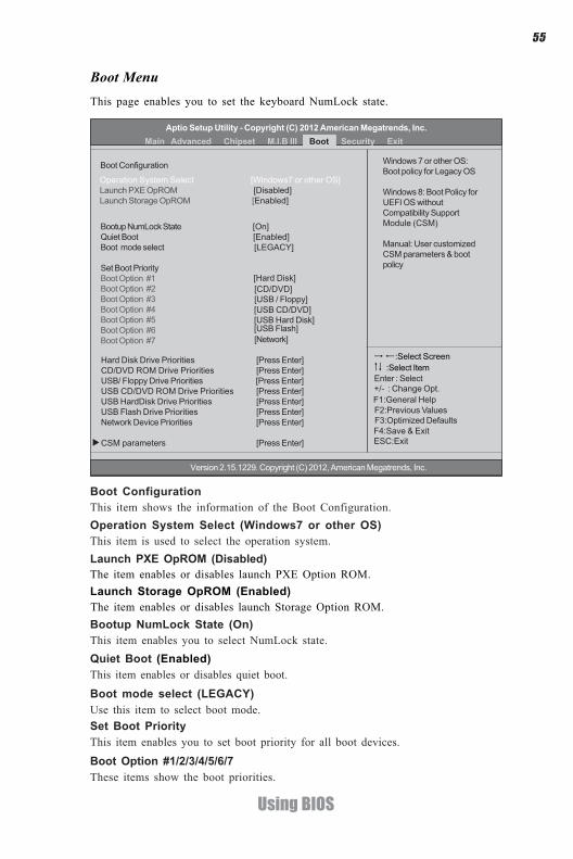
This page enables you to set the keyboard NumLock state.
Boot Menu
Boot ConfigurationThis item shows the information of the Boot Configuration.
Bootup NumLock State (On)This item enables you to select NumLock state.Quiet Boot (Enabled)This item enables or disables quiet boot.
Boot mode select (LEGACY)Use this item to select boot mode.
Operation System Select (Windows7 or other OS)This item is used to select the operation system.Launch PXE OpROM (Disabled)The item enables or disables launch PXE Option ROM.Launch Storage OpROM (Enabled)The item enables or disables launch Storage Option ROM.
Set Boot PriorityThis item enables you to set boot priority for all boot devices.
Boot Option #1/2/3/4/5/6/7These items show the boot priorities.
Aptio Setup Utility - Copyright (C) 2012 American Megatrends, Inc.
F1:General Help+/- : Change Opt.Enter : Select
:Select Screen:Select Item
F2:Previous Values F3:Optimized Defaults F4:Save & Exit ESC:Exit
Version 2.15.1229. Copyright (C) 2012, American Megatrends, Inc.
Main Advanced Chipset M.I.B III Boot Security Exit
Windows 7 or other OS:Boot policy for Legacy OS
Windows 8: Boot Policy forUEFI OS withoutCompatibility SupportModule (CSM)
Manual: User customizedCSM parameters & bootpolicy
Hard Disk Drive Priorities [Press Enter]CD/DVD ROM Drive Priorities [Press Enter]USB/ Floppy Drive Priorities [Press Enter]USB CD/DVD ROM Drive Priorities [Press Enter]USB HardDisk Drive Priorities [Press Enter]USB Flash Drive Priorities [Press Enter]Network Device Priorities [Press Enter]
CSM parameters [Press Enter]
Boot Configuration
Operation System Select [Windows7 or other OS]Launch PXE OpROM [Disabled]Launch Storage OpROM [Enabled]
Bootup NumLock State [On]Quiet Boot [Enabled]Boot mode select [LEGACY]
Set Boot PriorityBoot Option #1Boot Option #2Boot Option #3Boot Option #4Boot Option #5Boot Option #6Boot Option #7
[USB CD/DVD][USB Hard Disk][USB Flash][Network]
[USB / Floppy]
[Hard Disk] [CD/DVD]

56
Using BIOS
CSM parametersScroll to this item and press <Enter> to view the following screen.
Launch CSM
Boot option filter
Launch PXE OpROM policyThis controls the execution of UEFI and Legacy PXE OpROM.
Launch Storage OpROM policyThis controls the execution of UEFI and Legacy Storage OpROM.
Launch Video OpROM policyThis controls the execution of UEFI and Legacy Video OpROM.Other PCI device ROM priorityFor PCI devices other than Network, Mass storage or Video defines which OpROM tolaunch.
This option controls if CSM will be launched.
Press <Esc> to return to the Boot Menu page.
CSM parametersOpROM execution, boot options filter,etc.
This option controls what devices system can boot to.
Hard Disk / CD/DVD ROM / USB Floppy / USB CD/DVD ROM / USB HardDisk /USB Flash / Network Boot Drive PrioritiesThese items enable you to specify the sequence of loading the operating system.Press <Enter> to see the submenu.
Aptio Setup Utility - Copyright (C) 2012 American Megatrends, Inc.
F1:General Help+/- : Change Opt.Enter : Select
:Select Screen:Select Item
F2:Previous Values F3:Optimized Defaults F4:Save & Exit ESC:Exit
Version 2.15.1229. Copyright (C) 2012, American Megatrends, Inc.
Launch CSM [Always]Boot option filter [UEFI and Legacy]Launch PXE OpROM policy [Do not launch]Launch Storage OpROM policy [Legacy only]Launch Video OpROM policy [Legacy only]Other PCI device ROM priority [Legacy OpROM]
This option controls if CSMwill be launched
Main Advanced Chipset M.I.B III Boot Security Exit

57
Using BIOS
This page enables you to set setup administrator password and user password.
Security Menu
Administrator Password Status (Not Install)This item shows administrator password installed or not.User Password Status (Not Install)This item shows user password installed or not.
System Mode state (Setup)This item shows system mode setup or not.Secure Boot state (Disabled)This item allows you to enable or disable the secure boot state.
Secure Boot (Enabled)This item is used to control the secure boot flow, it is possible only if system runs inUser Mode.Secure Boot Mode (Custom)This item is used to select secure boot mode, when you select standard mode, secureboot policy is fixed; when you select custom mode, the image execution policy andsecure boot key databases are changeable.
Aptio Setup Utility - Copyright (C) 2012 American Megatrends, Inc.
F1:General Help+/- : Change Opt.Enter : Select
:Select Screen:Select Item
F2:Previous Values F3:Optimized Defaults F4:Save & Exit ESC:Exit
Version 2.15.1229. Copyright (C) 2012, American Megatrends, Inc.
Administrator Password Status Not InstallUser Password Status Not Install
Administrator Password
System Mode state SetupSecure Boot state Disabled
Secure Boot [Enabled]Secure Boot Mode [Custom]Image Execution Policy Key Management
Secure Boot mode selector. ‘Stan-dard’ -fixed Secure boot policy,‘Custom’ -changeable Image Ex-ecution policy and Secure Boot Keydata bases
Main Advanced Chipset M.I.B III Boot Security Exit

58
Using BIOS
Internal FV/Option ROM/Removable Media/Fixed Media (Always Execute/Deny Execute)These items allow you to select image execution policy per device path on securityviolation. Only users logged with administrative password can exercise query userpolicy setting.
Image Execution PolicyScroll to this item to view the following screen:
Press <Esc> to return to the Security Menu page.
Aptio Setup Utility - Copyright (C) 2012 American Megatrends, Inc.
F1:General Help+/- : Change Opt.Enter : Select
:Select Screen:Select Item
F2:Previous Values F3:Optimized Defaults F4:Save & Exit ESC:Exit
Version 2.15.1229. Copyright (C) 2012, American Megatrends, Inc.
Main Advanced Chipset M.I.B III Boot Security Exit
Image Execution Policy per devicepath on Security Violation. Note:Only users logged withAdministrative password canexercise Query User policy setting
Internal FV [Always Execute]Option ROM [Deny Execute]Removable Media [Deny Execute]Fixed Media [Deny Execute]
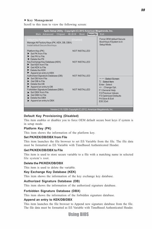
59
Using BIOS
Key ManagementScroll to this item to view the following screen:
Platform Key (PK)This item shows the information of the platform key.Set PK/KEK/DB/DBX from FileThis item launches the file browser to set Efi Variable from the file. The file datamust be formatted as Efi Variable with TimeBased Authenticated Header.
Get PK/KEK/DB/DBX to FileThis item is used to store secure variable to a file with a matching name in selectedfile system’s root.
Delete the PK/KEK/DB/DBXThis item is used to delete the variable.Key Exchange Key Database (KEK)This item shows the information of the key exchange key database.Authorized Signature Database (DB)This item shows the information of the authorized signature database.
Default Key Provisioning (Disabled)This item enables or disables you to force OEM default secure boot keys if system isin setup mode.
Append an entry to KEK/DB/DBXThis item launches the file browser to Append new signature database from the file.The file data must be formatted as Efi Variable with TimeBased Authenticated Header.
Forbidden Signature Database (DBX)This item shows the information of the forbidden signature database.
Aptio Setup Utility - Copyright (C) 2012 American Megatrends, Inc.
F1:General Help+/- : Change Opt.Enter : Select
:Select Screen:Select Item
F2:Previous Values F3:Optimized Defaults F4:Save & Exit ESC:Exit
Version 2.15.1229. Copyright (C) 2012, American Megatrends, Inc.
Force OEM default SecureBoot Keys if System is inSetup Mode.
Default Key Provisioning [Disabled]Manage All Factory Keys (PK, KEK, DB, DBX)Install default Secure Boot keys
Platform Key (PK) NOT INSTALLED Set PK from File
Get PK to File Delete the PKKey Exchange Key Database (KEK) NOT INSTALLED
Set KEK from File Get KEK to File Delete the KEK Append an entry to KEKAuthorized Signature Database (DB) NOT INSTALLED
Set DB from File Get DB to File Delete the DB Append an entry to DBForbidden Signature Database (DBX) NOT INSTALLED
Set DBX from File Get DBX to File Delete the DBX Append an entry to DBX
Main Advanced Chipset M.I.B III Boot Security Exit

60
Using BIOS
Save OptionsUse this item enables you to save the options that you have made.
Save ChangesUse this item enables you to save the changes that you have made.
Discard ChangesUse this item enables you to discard any changes that you have made.
Restore DefaultsUse this item enables you to restore the system defaults.
Save as User DefaultsUse this item enables you to save the changes that you have made as user defaults.
Restore User DefaultsUse this item enables you to restore user defaults to all the setup options.
Save Changes and ExitUse this item enables you to exit system setup after saving the changes.
Discard Changes and ExitUse this item enables you to exit system setup without saving any changes.
Save Changes and ResetUse this item enables you to reset the system setup after saving the changes.
Discard Changes and ResetUse this item enables you to reset system setup without saving any changes.
This page enables you to exit system setup after saving or without saving thechanges.
Exit Menu
Save Changes and ExitDiscard Changes and ExitSave Changes and ResetDiscard Changes and Reset
Save OptionsSave ChangesDiscard Changes
Restore DefaultsSave as User DefaultsRestore User Defaults
Boot Override +/- : Change Opt.
:Select Screen:Select Item
F1:General Help F2:Previous Values F3:Optimized Defaults F4:Save & Exit ESC:Exit
Enter : Select
Exit system setup after savingthe changes.
Main Advanced Chipset M.I.B III Boot Security ExitAptio Setup Utility - Copyright (C) 2012 American Megatrends, Inc.
Version 2.15.1229. Copyright (C) 2012, American Megatrends, Inc.
61
Using BIOS
Updating the BIOSYou can download and install updated BIOS for this motherboard from themanufacturer’s Web site. New BIOS provides support for new peripherals, improve-ments in performance, or fixes for known bugs. Install new BIOS as follows:
This concludes Chapter 3. Refer to the next chapter for information on the softwaresupplied with the motherboard.
1 If your motherboard has a BIOS protection jumper, change the setting toallow BIOS flashing.
2 If your motherboard has an item called Firmware Write Protect in Ad-vanced BIOS features, disable it. (Firmware Write Protect preventsBIOS from being overwritten.)
3 Prepare a bootable device or create a bootable system disk. (Refer toWindows online help for information on creating a bootable systemdisk.)
4 Download the Flash Utility and new BIOS file from the manufacturer’sWeb site. Copy these files to the bootable device.
5 Turn off your computer and insert the bootable device in your com-puter. (You might need to run the Setup Utility and change the the bootpriority items on the Advanced BIOS Features Setup page, to forceyour computer to boot from the bootable device first.)
6 At the C:\ or A:\ prompt, type the Flash Utility program name and the filename of the new BIOS and then press <Enter>. Example: AFUDOS.EXE040706.ROM
7 When the installation is complete, remove the bootable device from thecomputer and restart your computer. If your motherboard has a FlashBIOS jumper, reset the jumper to protect the newly installed BIOS frombeing overwritten. The computer will restart automatically.
Boot OverrideUse this item enables you to set the device order.

62
Using BIOS
Memo

63
Using the Motherboard Software
Chapter 4
Using the Motherboard Software
The auto-install DVD-ROM makes it easy for you to install the drivers and software.The support software DVD-ROM disc loads automatically under Windows XP/7/8.When you insert the DVD-ROM disc in the DVD-ROM drive, the auto-run featurewill automatically bring up the installation screen. The screen has four buttons on it:Setup, Utilities, Browse CD and Exit.
Auto-installing under Windows XP/7/8
Displays the path for allsoftware and driversavailable on the disk.
Open Windows Explorerand show the contentsof the support disk.
Click “Exit” button toclose the Auto-Setupwindow.
Browse CD:
Click the “Setup”button to select andrun the softwareinstallation program.
Click the “ Utilities”button to select andinstall ECS IntelligentUtility.
Information:
Follow these instructions to install device drivers and software for the motherboard:
The following screens are examples only. The screens and driver lists willbe different according to the motherboard you are installing.
1. Click Setup. The installation program begins:
Running Setup
The motherboard identification is located in the upper left-hand corner.

64
Using the Motherboard Software
2. Click Next. The following screen appears:
3. Check the box next to the items you want to install. The default options are recommended.
5. Follow the instructions on the screen to install the items.
Drivers and software are automatically installed in sequence. Follow theonscreen instructions, confirm commands and allow the computer torestart a few times to complete the installation.Windows 8 will show the following screen after system restart, youmust select “Desktop” in the bottom left to install the next driver.
4. Click Next to run the Installation Wizard. An item installation screen appears:
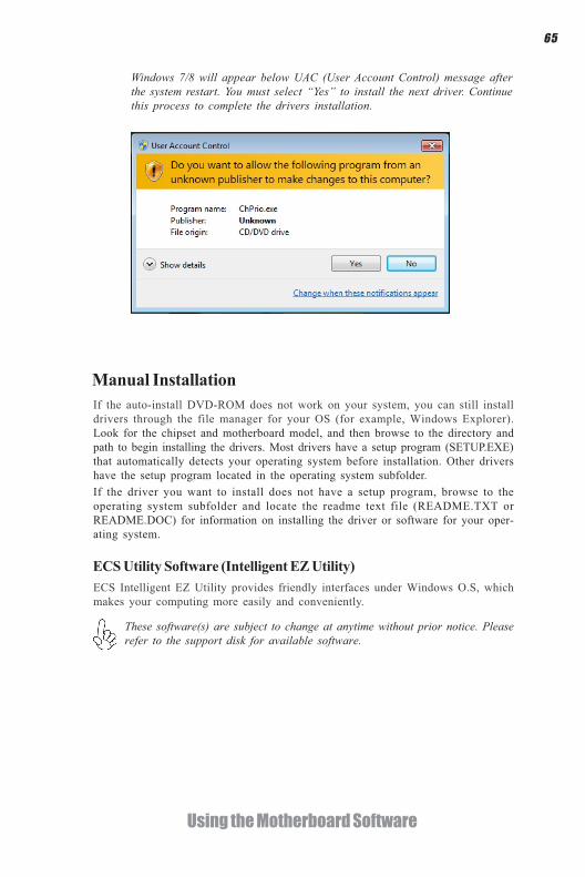
65
Using the Motherboard Software
Windows 7/8 will appear below UAC (User Account Control) message afterthe system restart. You must select “Yes” to install the next driver. Continuethis process to complete the drivers installation.
If the auto-install DVD-ROM does not work on your system, you can still installdrivers through the file manager for your OS (for example, Windows Explorer).Look for the chipset and motherboard model, and then browse to the directory andpath to begin installing the drivers. Most drivers have a setup program (SETUP.EXE)that automatically detects your operating system before installation. Other drivershave the setup program located in the operating system subfolder.
Manual Installation
ECS Utility Software (Intelligent EZ Utility)ECS Intelligent EZ Utility provides friendly interfaces under Windows O.S, whichmakes your computing more easily and conveniently.
If the driver you want to install does not have a setup program, browse to theoperating system subfolder and locate the readme text file (README.TXT orREADME.DOC) for information on installing the driver or software for your oper-ating system.
These software(s) are subject to change at anytime without prior notice. Pleaserefer to the support disk for available software.

66
Using the Motherboard Software
eBLUECS eBLU utility makes BIOS update faster and easier. eBLU will list the latest BIOSwith a default check-mark. Click”install” button to install.
eDLUECS eDLU utility makes updating drivers fast and easy. eDLU saves time and hassleby listing all the latest drivers online. Just select the one you prefer and start todownload and install the drivers.
eSFeSF(Smart Fan) utility provides easy and safe way to adjust fan speed in accordancewith your PC’s system loading and temperature.It has five modes to adjust fan speed in a safe range without entering the BIOS tooptimize your system cooling environment.
Microsoft .NET Framework 3.5 is required.
Microsoft .NET Framework 3.5 is required.

67
Trouble Shooting
Chapter 5
Trouble Shooting
Start up problems during assembly
After assembling the PC for the first time you may experience some start upproblems. Before calling for technical support or returning for warranty, this chaptermay help to address some of the common questions using some basic troubleshootingtips.
a) System does not power up and the fans are not running.
1.Disassemble the PC to remove the VGA adaptor card, DDR memory, LAN, USBand other peripherals including keyboard and mouse. Leave only the motherboard,CPU with CPU cooler and power supply connected. Turn on again to see if theCPU and power supply fans are running.
2. Make sure to remove any unused screws or other metal objects such as screwdriversfrom the inside PC case. This is to prevent damage from short circuit.
3. Check the CPU FAN connector is connected to the motherboard.
4. For Intel platforms check the pins on the CPU socket for damage or bent. A bentpin may cause failure to boot and sometimes permanent damage from short circuit.
5. Check the 12V power connector is connected to the motherboard.
6. Check that the 12V power & ATX connectors are fully inserted into themotherboard connectors. Make sure the latches of the cable and connector arelocked into place.
b) Power is on, fans are running but there is no display
1. Make sure the monitor is turned on and the monitor cable is properly connectedto the PC.
2. Check the VGA adapter card (if applicable) is inserted properly.
3. Listen for beep sounds. If you are using internal PC speaker make sure it isconnected. a. continuous 3 short beeps: memory not detected b. 1 long beep and 8 short beeps: VGA not detected
c) The PC suddenly shuts down while booting up.1. The CPU may experience overheating so it will shutdown to protect itself.Ensure the CPU fan is working properly.

68
Trouble Shooting
Your computer, like any electrical appliance, requires proper care and maintenance.Here are some basic PC care tips to help prolong the life of the motherboard andkeep it running as best as it can.
Start up problems after prolong useAfter a prolong period of use your PC may experience start up problems again.This may be caused by breakdown of devices connected to the motherboard such asHDD, CPU fan, etc. The following tips may help to revive the PC or identify thecause of failure.1. Clear the CMOS values using the CLR_CMOS jumper. Refer to CLR_CMOSjumper in Chapter 2 for Checking Jumper Settings in this user manual. Whencompleted, follow up with a Load Optimised Default in the BIOS setup.
2. Check the CPU cooler fan for dust. Long term accumulation of dust will reduceits effectiveness to cool the processor. Clean the cooler or replace a new one ifnecessary.
3. Check that the 12V power & ATX connectors are fully inserted into themotherboard connectors. Make sure the latches of the cable and connector arelocked into place.
4. Remove the hard drive, optical drive or DDR memory to determine which ofthese components may be at fault.
Maintenance and care tips
2. From the BIOS setting, try to disable the Smartfan function to let the fan run atdefault speed. Doing a Load Optimised Default will also disable the Smartfan.
1. Keep your computer in a well ventilated area. Leave some space between the PC and the wall for sufficient airflow.
2. Keep your computer in a cool dry place. Avoid dusty areas, direct sunlight and areas of high moisture content.
3. Routinely clean the CPU cooler fan to remove dust and hair.
4. In places of hot and humid weather you should turn on your computer once every other week to circulate the air and prevent damage from humility.
5. Add more memory to your computer if possible. This not only speeds up the system but also reduces the loading of your hard drive to prolong its life span.
6. If possible, ensure the power cord has an earth ground pin directly from the wall outlet. This will reduce voltage fluctuation that may damage sensitive devices.
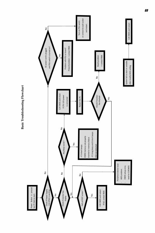
Pow
er B
uon
is
pres
sed
but P
C fa
ils to
star
t.
Yes
Chec
k if
Pow
er S
uppl
y Un
it(P
SU) i
s wor
king
No NoAn
y Be
ep so
und
NoCL
R CM
OS a
nd ch
eck
if CP
U 12
V po
wer
is co
nnec
ted
art t
he P
C st
Re
Prob
lem
with
PSU
or b
oard
?
If bo
ard
prob
lem
-> co
ntac
t RM
A
AC p
ower
cord
is p
lued
gg
and
PSU
switc
h is
turn
ed o
n?
Yes
oble
m
rBo
ard
p
-> co
ntac
t RM
A
No
- If 3
shor
t bee
ps:
DIM
M m
emor
y no
t pro
perly
inse
rted
or m
emor
y fa
ilure
- If 1
long
bee
p an
d 8
shor
t bee
ps:
VGA
not d
etec
ted
Yes
Yes
Halt
at P
OST
scre
en
Yes
R CM
OLC
S an
d re
star
t.
If fa
il, co
ntac
t RM
A
Yes
No
Perip
hera
l dev
ice is
sue
-HD
D pr
oble
m.
-CM
OS se
tup
erro
r,
dne
e to
CLR
CMOS
. Sy
stem
fail
to st
art o
r uns
tabl
e
aer
mod
ify B
IOS
seng
. M
CLR
COS
and
rest
art
Turn
on
PSU
switc
h
or co
nnec
t to
wal
l soc
ket
star
t. e
and
rNo
Chec
k if
mon
itor h
sadi
s pla
y
Chec
k if
mon
itor
has
disp
lay 6
69
Basic
Tro
uble
shoo
ting
Flow
char
t

70
Trouble Shooting
Memo