Embed Size (px)
Citation preview
1
Kavaya – IIP-2004
Summary of NASA Laser/Lidar Working Group Status
by
Michael J. KavayaNASA Langley Research Center
Bruce M. GentryNASA Goddard Space Flight Center
to
Working Group on Space-Based Lidar WindsJan. 17-20, 2006Key West, Florida
2
Kavaya – IIP-2004
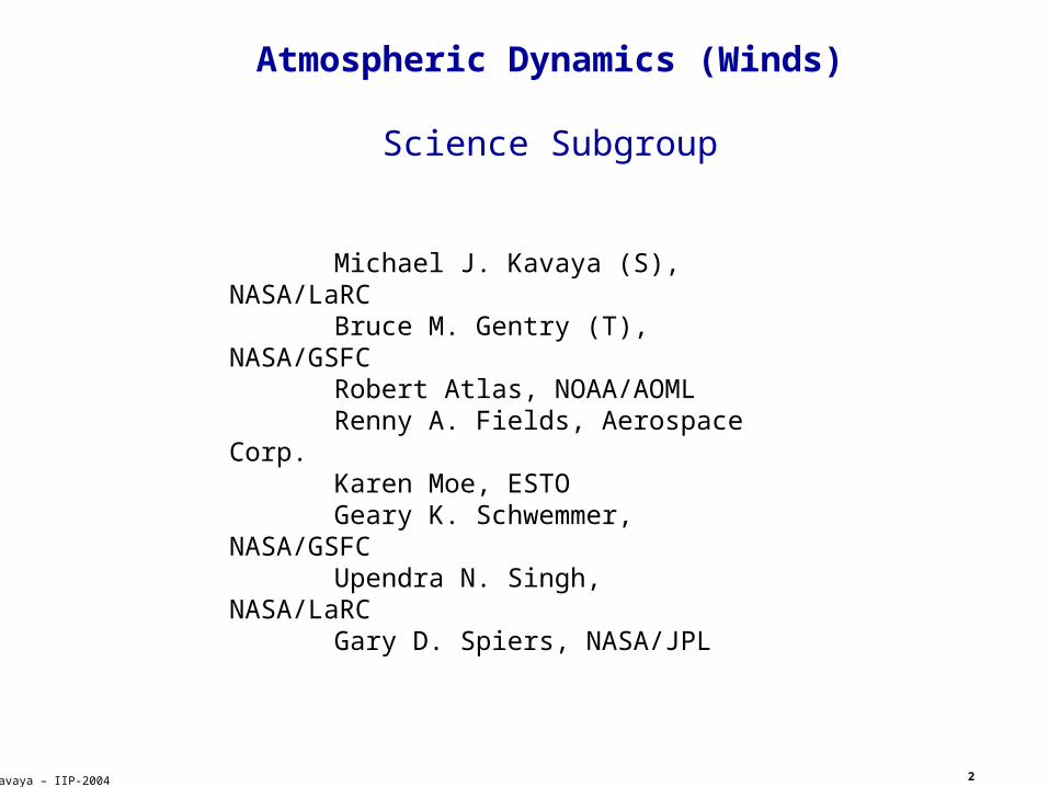
Atmospheric Dynamics (Winds)
Science Subgroup
Michael J. Kavaya (S), NASA/LaRC
Bruce M. Gentry (T), NASA/GSFC
Robert Atlas, NOAA/AOMLRenny A. Fields, Aerospace
Corp.Karen Moe, ESTOGeary K. Schwemmer,
NASA/GSFCUpendra N. Singh,
NASA/LaRCGary D. Spiers, NASA/JPL
(S) = Science lead (T) = Technology lead

3
Kavaya – IIP-2004
Overview of Requirement Definition Process
Measurement Scenarios
Measurement Scenarios
Technology ChallengesTechnology Challenges
Laser Transmitter
Laser Transmitter
Data Acquisition
Data Acquisition
Capability Breakdown
Structure (CBS)
Capability Breakdown
Structure (CBS)
Final ReportFinal Report
RoadmapsRoadmaps
Atmospheric CompositionAtmospheric Composition
Atmospheric Dynamics
Atmospheric Dynamics
Topography & Oceans
Topography & Oceans
Detection, Processing,
Optics
Detection, Processing,
Optics
Data Utilization
Data Utilization
Science RequirementsScience RequirementsPhase A:
Science
Phase B: Technolog
y
Phase C: Integrat
ion
4
Kavaya – IIP-2004
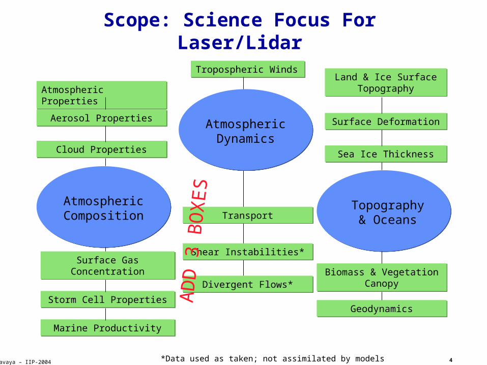
Scope: Science Focus For Laser/Lidar
Atmospheric Dynamics
Atmospheric Composition
Topography & Oceans
Tropospheric WindsTropospheric Winds
Atmospheric PropertiesAtmospheric Properties
Aerosol PropertiesAerosol Properties
Cloud PropertiesCloud Properties
Land & Ice Surface Topography
Land & Ice Surface Topography
Surface DeformationSurface Deformation
Sea Ice ThicknessSea Ice Thickness
Biomass & Vegetation Canopy
Biomass & Vegetation Canopy
GeodynamicsGeodynamics
Surface Gas ConcentrationSurface Gas Concentration
Storm Cell PropertiesStorm Cell Properties
Marine ProductivityMarine Productivity
TransportTransport
Shear Instabilities*Shear Instabilities*
Divergent Flows*Divergent Flows*
*Data used as taken; not assimilated by models
ADD 3 BOXES
5
Kavaya – IIP-2004
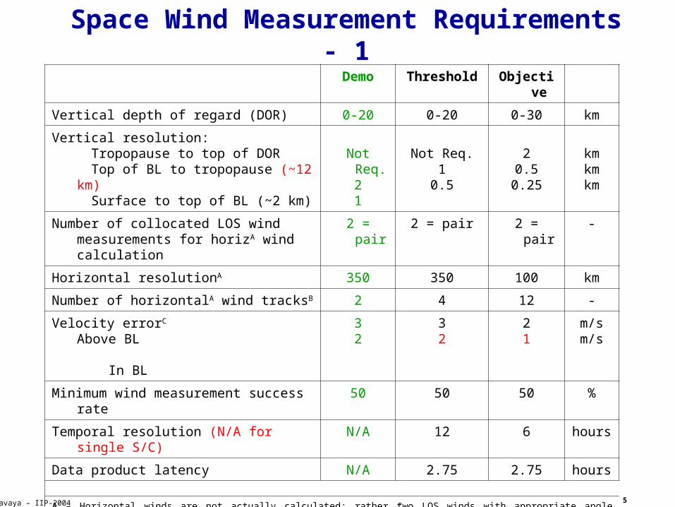
Space Wind Measurement Requirements - 1Demo Threshold Objective
Vertical depth of regard (DOR) 0-20 0-20 0-30 km
Vertical resolution: Tropopause to top of DOR Top of BL to tropopause (~12 km) Surface to top of BL (~2 km)
Not Req.21
Not Req.1
0.5
20.5
0.25
kmkmkm
Number of collocated LOS wind measurements for horizA wind calculation
2 = pair 2 = pair 2 = pair -
Horizontal resolutionA 350 350 100 km
Number of horizontalA wind tracksB 2 4 12 -
Velocity errorC Above BL In BL
32
32
21
m/sm/s
Minimum wind measurement success rate 50 50 50 %
Temporal resolution (N/A for single S/C) N/A 12 6 hours
Data product latency N/A 2.75 2.75 hours
A – Horizontal winds are not actually calculated; rather two LOS winds with appropriate angle spacing and collocation are measured for an “effective” horizontal wind measurement. The two LOS winds are reported to the user.
B – The 4 cross-track measurements do not have to occur at the same along-track coordinate; staggering is OK.C – Error = 1 LOS wind random error, projected to a horizontal plane; from all lidar, geometry, pointing, atmosphere, signal processing, and
sampling effects. The true wind is defined as the linear average, over a 100 x 100 km box (or 175 km or 25 km) box centered on the LOS wind location, of the true 3-D wind projected onto the lidar beam direction provided with the data.
(original errata that have been corrected) (Added to/clarified requirements during NASA ESTO ESTIPS Laser/Lidar Working Group)
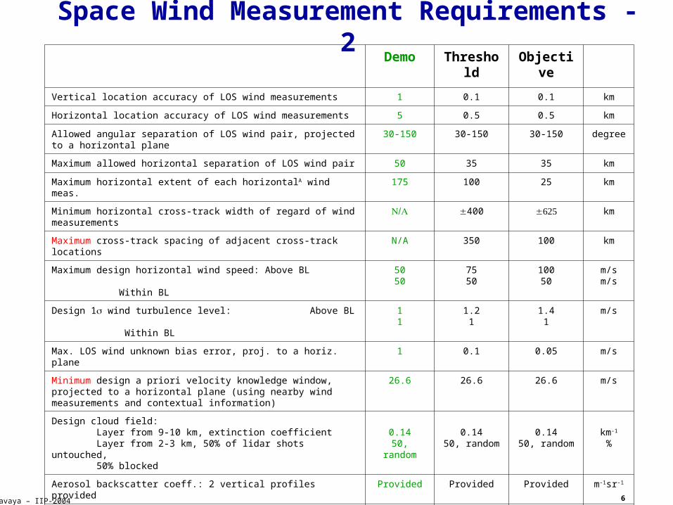
6
Kavaya – IIP-2004
Space Wind Measurement Requirements - 2
Demo Threshold Objective
Vertical location accuracy of LOS wind measurements 1 0.1 0.1 km
Horizontal location accuracy of LOS wind measurements 5 0.5 0.5 km
Allowed angular separation of LOS wind pair, projected to a horizontal plane 30-150 30-150 30-150 degree
Maximum allowed horizontal separation of LOS wind pair 50 35 35 km
Maximum horizontal extent of each horizontalA wind meas. 175 100 25 km
Minimum horizontal cross-track width of regard of wind measurements 400 km
Maximum cross-track spacing of adjacent cross-track locations N/A 350 100 km
Maximum design horizontal wind speed: Above BL Within BL
5050
7550
10050
m/sm/s
Design 1 wind turbulence level: Above BL Within BL
11
1.21
1.41
m/s
Max. LOS wind unknown bias error, proj. to a horiz. plane 1 0.1 0.05 m/s
Minimum design a priori velocity knowledge window, projected to a horizontal plane (using nearby wind measurements and contextual information)
26.6 26.6 26.6 m/s
Design cloud field: Layer from 9-10 km, extinction coefficient Layer from 2-3 km, 50% of lidar shots untouched, 50% blocked
0.1450, random
0.1450, random
0.1450, random
km-1
%
Aerosol backscatter coeff.: 2 vertical profiles provided Provided Provided Provided m-1sr-1
Aerosol backscatter: Probability density function (PDF) PDF width
LognormalProvided
LognormalProvided
LognormalProvided
m srm-1sr-1
Atmospheric extinction coefficient: 2 vertical profiles provided Provided Provided Provided km-1
Orbit latitude coverage N/A 80N to 80S 80N to 80S Degree
Downlinked data All All TBD -
(original errata that have been corrected) (Added to/clarified requirements during NASA ESTO ESTIPS Laser/Lidar Working Group)
7
Kavaya – IIP-2004
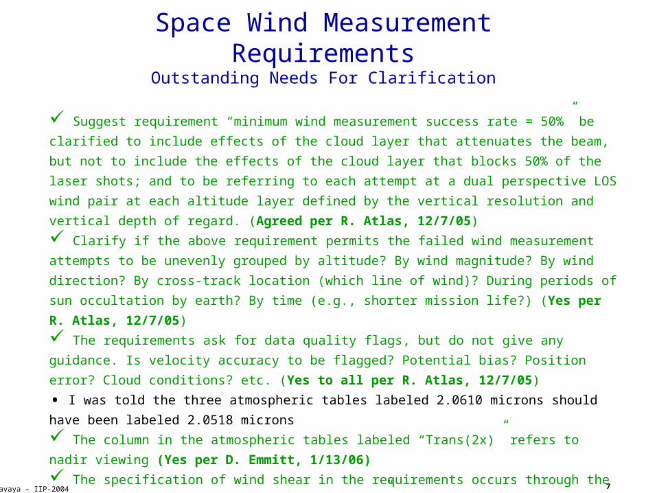
Space Wind Measurement RequirementsOutstanding Needs For Clarification
Suggest requirement “minimum wind measurement success rate = 50%” be
clarified to include effects of the cloud layer that attenuates the beam,
but not to include the effects of the cloud layer that blocks 50% of the
laser shots; and to be referring to each attempt at a dual perspective LOS
wind pair at each altitude layer defined by the vertical resolution and
vertical depth of regard. (Agreed per R. Atlas, 12/7/05)
Clarify if the above requirement permits the failed wind measurement
attempts to be unevenly grouped by altitude? By wind magnitude? By wind
direction? By cross-track location (which line of wind)? During periods of
sun occultation by earth? By time (e.g., shorter mission life?) (Yes per
R. Atlas, 12/7/05)
The requirements ask for data quality flags, but do not give any
guidance. Is velocity accuracy to be flagged? Potential bias? Position
error? Cloud conditions? etc. (Yes to all per R. Atlas, 12/7/05)
• I was told the three atmospheric tables labeled 2.0610 microns should have been labeled 2.0518 microns
The column in the atmospheric tables labeled “Trans(2x)” refers to
nadir viewing (Yes per D. Emmitt, 1/13/06)
The specification of wind shear in the requirements occurs through the
column in the atmospheric tables labeled “U”. The wind velocity should
always be assumed to be in the direction of the horizontally projected
laser beam. (Yes per D. Emmitt, 1/13/06)
(Added to/clarified requirements during NASA ESTO ESTIPS Laser/Lidar
Working Group)
8
Kavaya – IIP-2004
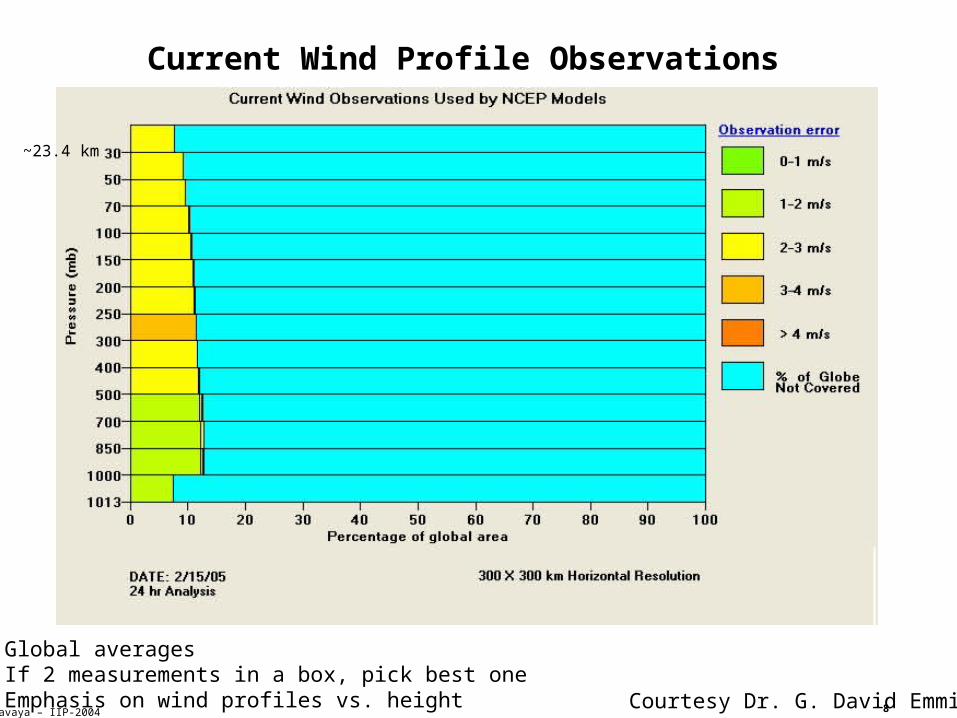
Current Wind Profile Observations
Courtesy Dr. G. David Emmitt
• Global averages• If 2 measurements in a box, pick best one• Emphasis on wind profiles vs. height
~23.4 km
9
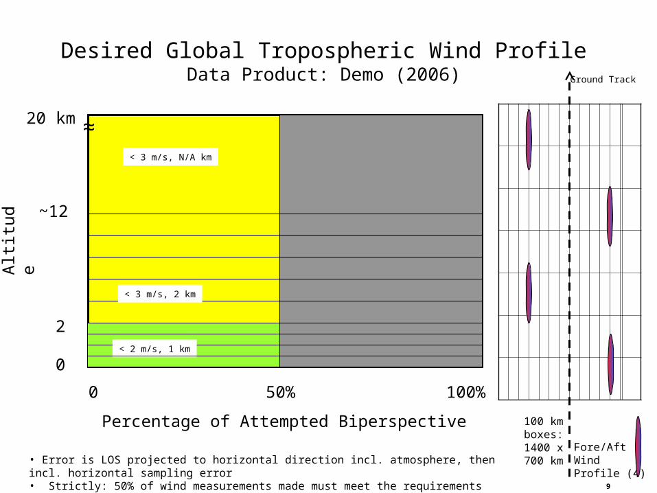
Percentage of Attempted Biperspective
• Error is LOS projected to horizontal direction incl. atmosphere, then incl. horizontal sampling error• Strictly: 50% of wind measurements made must meet the requirements
Desired Global Tropospheric Wind ProfileData Product: Demo (2006)
Alti
tud
e
2
20 km
0
100%0
~12
50%
< 2 m/s, 1 km
< 3 m/s, 2 km
< 3 m/s, N/A km
Fore/AftWindProfile (4)
100 kmboxes:1400 x700 km
Ground Track
≈
10
Alti
tud
e
2
20 km
0
100%0
• Error is LOS projected to horizontal direction incl. atmosphere, then incl. horizontal sampling error• Strictly: 50% of wind measurements made must meet the requirements
~12
50%
< 3 m/s, N/A km
Desired Global Tropospheric Wind ProfileData Product: Threshold (NASA/NOAA, 2001)
Fore/AftWindProfile (8)
Ground Track
< 2 m/s, 0.5 km
< 3 m/s, 1 km
≈
100 kmboxes:1400 x700 km
Percentage of Attempted Biperspective
11
Fore/AftWindProfile (84)
Alti
tud
e
2
20 km
0
100%0
• Error is LOS projected to horizontal direction incl. atmosphere, then incl. horizontal sampling error• Strictly: 50% of wind measurements made must meet the requirements
~12
50%
< 2 m/s, 2 km
Desired Global Tropospheric Wind ProfileData Product: Objective (NASA/NOAA, 2001)
30 kmGround Track
< 2 m/s, 0.5 km
< 1 m/s, 0.25 km
≈
100 kmboxes:1400 x700 km
Percentage of Attempted Biperspective
12
Kavaya – IIP-2004
ZORBIT
RCT,MAX
30° fore/aft anglein horiz. Plane (required 30-
150°)
FOREAFT
Two Perspectives /MeasurementNadir Angle Depends on RCT,MAX
L
SF = 75°SA = 105°
ZORBIT RCT,MAX L,MIN
400 km 200 km 27°
400 km 300 km 37°
400 km 400 km 45°
833 km 400 km 26°
833 km 500 km 31°
833 km 600 km 36°
833 km 700 km 40°
13
Kavaya – IIP-2004
Atmospheric Winds
Recommended Roadmap
Past
1 Micron Altimetry
2 Micron Winds
0.355 & 2 Micron Winds
0.355 & 2 Micron WindsSpace-like Geometry & Scanning
0.355 & 2 Micron WindsNPOESS833 kmDemo
0.355 & 2 Micron WindsNASA400 km
Threshold, 3 yr.
Œ
Ž
14
Kavaya – IIP-2004
Conclusions
• The NASA Laser/Lidar Working Group is trying to do a very ambitious undertaking in a short amount of time with a few volunteers
• For the winds portion, we are trying to clarify, correct, and extend the NASA/NOAA 2001 wind measurement requirements to include a logical demonstration space mission
• Space mission scenarios are proposed to try to cover the possible technologies that will be needed
• We are working with Dave Emmitt to provide vetted lidar technology requirements to go with the scenarios
• The final report may influence NASA’s future funding of lidar technologies
• We welcome inputs from the community
15
BACK UP SLIDES
16
Kavaya – IIP-2004
Space Wind Measurement RequirementsComments
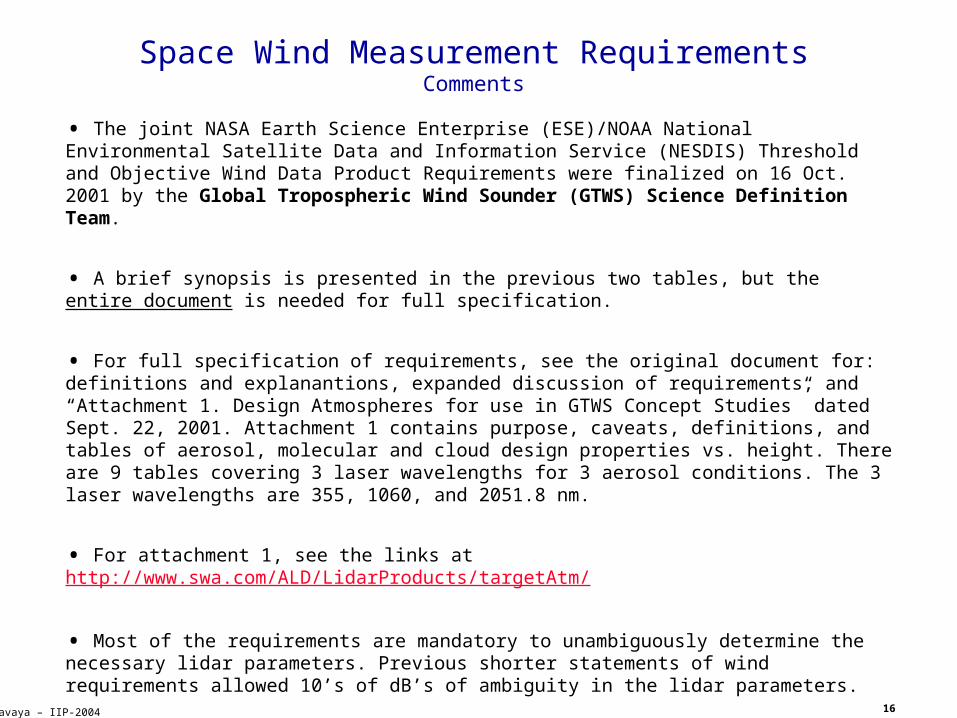
• The joint NASA Earth Science Enterprise (ESE)/NOAA National Environmental Satellite Data and Information Service (NESDIS) Threshold and Objective Wind Data Product Requirements were finalized on 16 Oct. 2001 by the Global Tropospheric Wind Sounder (GTWS) Science Definition Team.
• A brief synopsis is presented in the previous two tables, but the entire document is needed for full specification.
• For full specification of requirements, see the original document for: definitions and explanantions, expanded discussion of requirements, and “Attachment 1. Design Atmospheres for use in GTWS Concept Studies” dated Sept. 22, 2001. Attachment 1 contains purpose, caveats, definitions, and tables of aerosol, molecular and cloud design properties vs. height. There are 9 tables covering 3 laser wavelengths for 3 aerosol conditions. The 3 laser wavelengths are 355, 1060, and 2051.8 nm.
• For attachment 1, see the links at http://www.swa.com/ALD/LidarProducts/targetAtm/
• Most of the requirements are mandatory to unambiguously determine the necessary lidar parameters. Previous shorter statements of wind requirements allowed 10’s of dB’s of ambiguity in the lidar parameters.
• GTWS Science Definition Team:Dr. Robert Atlas, NASA/GSFC, co-lead (now Director NOAA/AOML)Dr. Jim Yoe, NOAA/NESDIS, co-leadDr. Wayman Baker, NOAA/NWS; Dr. G. David. Emmitt, Simpson Weather Associates; Dr. Rod Frehlich, Univ. of Colorado; Dr. Donald R. Johnson, Univ. of Wisconsin; Dr. Steve Koch, NOAA/OAR/FSL; Dr. T. N. Krishnamurti, Florida State Univ.; Dr. Frank Marks, NOAA/AOML; Dr. Robert T. Menzies, NASA/JPL; Dr. Jan Paegle, Univ. of Utah
17
Kavaya – IIP-2004
Space Wind Measurement RequirementsText From Requirements Document - 1
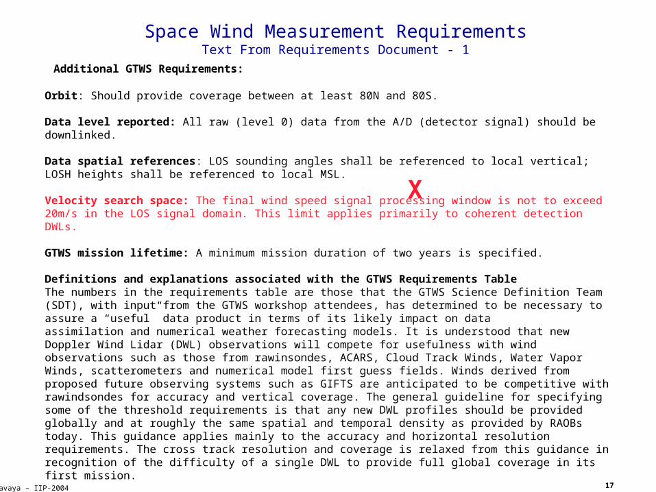
Additional GTWS Requirements:
Orbit: Should provide coverage between at least 80N and 80S.
Data level reported: All raw (level 0) data from the A/D (detector signal) should be downlinked.
Data spatial references: LOS sounding angles shall be referenced to local vertical; LOSH heights shall be referenced to local MSL.
Velocity search space: The final wind speed signal processing window is not to exceed 20m/s in the LOS signal domain. This limit applies primarily to coherent detection DWLs.
GTWS mission lifetime: A minimum mission duration of two years is specified.
Definitions and explanations associated with the GTWS Requirements TableThe numbers in the requirements table are those that the GTWS Science Definition Team (SDT), with input from the GTWS workshop attendees, has determined to be necessary to assure a “useful” data product in terms of its likely impact on dataassimilation and numerical weather forecasting models. It is understood that new Doppler Wind Lidar (DWL) observations will compete for usefulness with wind observations such as those from rawinsondes, ACARS, Cloud Track Winds, Water Vapor Winds, scatterometers and numerical model first guess fields. Winds derived from proposed future observing systems such as GIFTS are anticipated to be competitive with rawindsondes for accuracy and vertical coverage. The general guideline for specifying some of the threshold requirements is that any new DWL profiles should be provided globally and at roughly the same spatial and temporal density as provided by RAOBs today. This guidance applies mainly to the accuracy and horizontal resolution requirements. The cross track resolution and coverage is relaxed from this guidance in recognition of the difficulty of a single DWL to provide full global coverage in its first mission.
OBJECTIVE: These values represent the desired data requirement for space-based lidar winds. The SDT is confident that an instrument meeting the objective requirements would have a significant impact on both science and operational weather prediction in the 2005 – 2010 time frame.
THRESHOLD: These values represent the minimum data requirements for space-based lidar winds. A GTWS instrument that meets the threshold requirements would likely result in meaningful impact on science and operational weather prediction.
X
18
Kavaya – IIP-2004
Space Wind Measurement RequirementsText From Requirements Document - 2
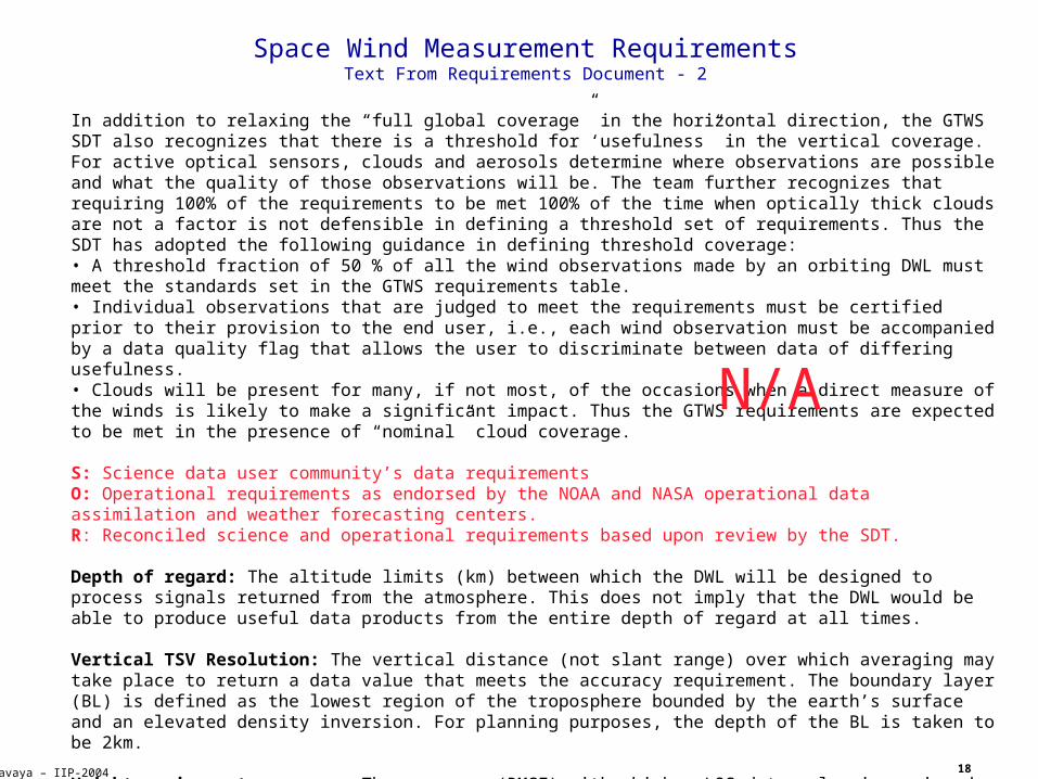
In addition to relaxing the “full global coverage” in the horizontal direction, the GTWS SDT also recognizes that there is a threshold for ‘usefulness” in the vertical coverage. For active optical sensors, clouds and aerosols determine where observations are possible and what the quality of those observations will be. The team further recognizes that requiring 100% of the requirements to be met 100% of the time when optically thick clouds are not a factor is not defensible in defining a threshold set of requirements. Thus the SDT has adopted the following guidance in defining threshold coverage:• A threshold fraction of 50 % of all the wind observations made by an orbiting DWL must meet the standards set in the GTWS requirements table.• Individual observations that are judged to meet the requirements must be certified prior to their provision to the end user, i.e., each wind observation must be accompanied by a data quality flag that allows the user to discriminate between data of differing usefulness.• Clouds will be present for many, if not most, of the occasions when a direct measure of the winds is likely to make a significant impact. Thus the GTWS requirements are expected to be met in the presence of “nominal” cloud coverage.
S: Science data user community’s data requirementsO: Operational requirements as endorsed by the NOAA and NASA operational data assimilation and weather forecasting centers.R: Reconciled science and operational requirements based upon review by the SDT.
Depth of regard: The altitude limits (km) between which the DWL will be designed to process signals returned from the atmosphere. This does not imply that the DWL would be able to produce useful data products from the entire depth of regard at all times.
Vertical TSV Resolution: The vertical distance (not slant range) over which averaging may take place to return a data value that meets the accuracy requirement. The boundary layer (BL) is defined as the lowest region of the troposphere bounded by the earth’s surface and an elevated density inversion. For planning purposes, the depth of the BL is taken to be 2km.
Height assignment accuracy: The accuracy (RMSE) with which a LOS data value is assigned to the height that most properly represents the signal weighted mean of the averaged velocity information.
N/A
19
Kavaya – IIP-2004
Space Wind Measurement RequirementsText From Requirements Document - 3
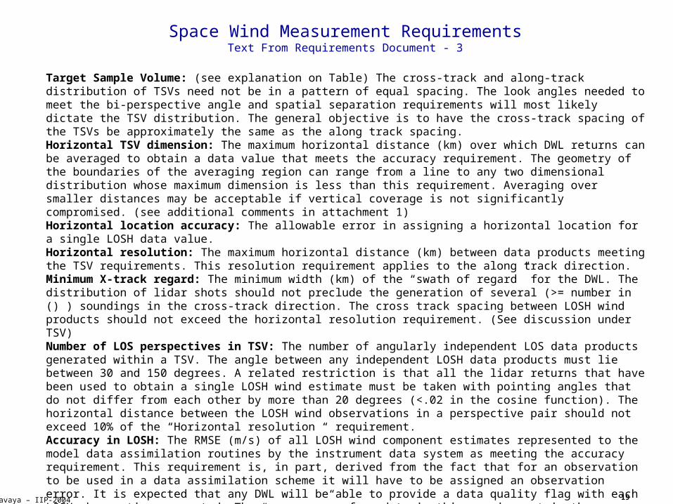
Target Sample Volume: (see explanation on Table) The cross-track and along-track distribution of TSVs need not be in a pattern of equal spacing. The look angles needed to meet the bi-perspective angle and spatial separation requirements will most likely dictate the TSV distribution. The general objective is to have the cross-track spacing of the TSVs be approximately the same as the along track spacing.Horizontal TSV dimension: The maximum horizontal distance (km) over which DWL returns can be averaged to obtain a data value that meets the accuracy requirement. The geometry of the boundaries of the averaging region can range from a line to any two dimensional distribution whose maximum dimension is less than this requirement. Averaging over smaller distances may be acceptable if vertical coverage is not significantly compromised. (see additional comments in attachment 1)Horizontal location accuracy: The allowable error in assigning a horizontal location for a single LOSH data value.Horizontal resolution: The maximum horizontal distance (km) between data products meeting the TSV requirements. This resolution requirement applies to the along track direction.Minimum X-track regard: The minimum width (km) of the “swath of regard” for the DWL. The distribution of lidar shots should not preclude the generation of several (>= number in () ) soundings in the cross-track direction. The cross track spacing between LOSH wind products should not exceed the horizontal resolution requirement. (See discussion under TSV)Number of LOS perspectives in TSV: The number of angularly independent LOS data products generated within a TSV. The angle between any independent LOSH data products must lie between 30 and 150 degrees. A related restriction is that all the lidar returns that have been used to obtain a single LOSH wind estimate must be taken with pointing angles that do not differ from each other by more than 20 degrees (<.02 in the cosine function). The horizontal distance between the LOSH wind observations in a perspective pair should not exceed 10% of the “Horizontal resolution “ requirement.Accuracy in LOSH: The RMSE (m/s) of all LOSH wind component estimates represented to the model data assimilation routines by the instrument data system as meeting the accuracy requirement. This requirement is, in part, derived from the fact that for an observation to be used in a data assimilation scheme it will have to be assigned an observation error. It is expected that any DWL will be able to provide a data quality flag with each LOSH observation generated. The “accuracy” referred to in this requirement is the measurement accuracy of the instrument. It includes all known sources of error such as pointing knowledge, frequency jitter, signal processing uncertainty and atmospheric turbulence. The LOSH accuracy is defined as the total estimation error projected onto thehorizontal plane for the average motion of the backscatter media within the illuminated volume along a LOS perspective. For example, a LOS estimation error of 1.5 m/s with a DWL using a 30 degree nadir scan angle would result in a 3.0 m/s uncertainty in the LOSH component. This accuracy requirement is expressed for both the BL and the rest of the troposphere. A set of “Design Atmospheres” will be provided to serve in establishing a point design. (see attached examples in Attachment 1.
20
Kavaya – IIP-2004
Space Wind Measurement RequirementsText From Requirements Document - 4
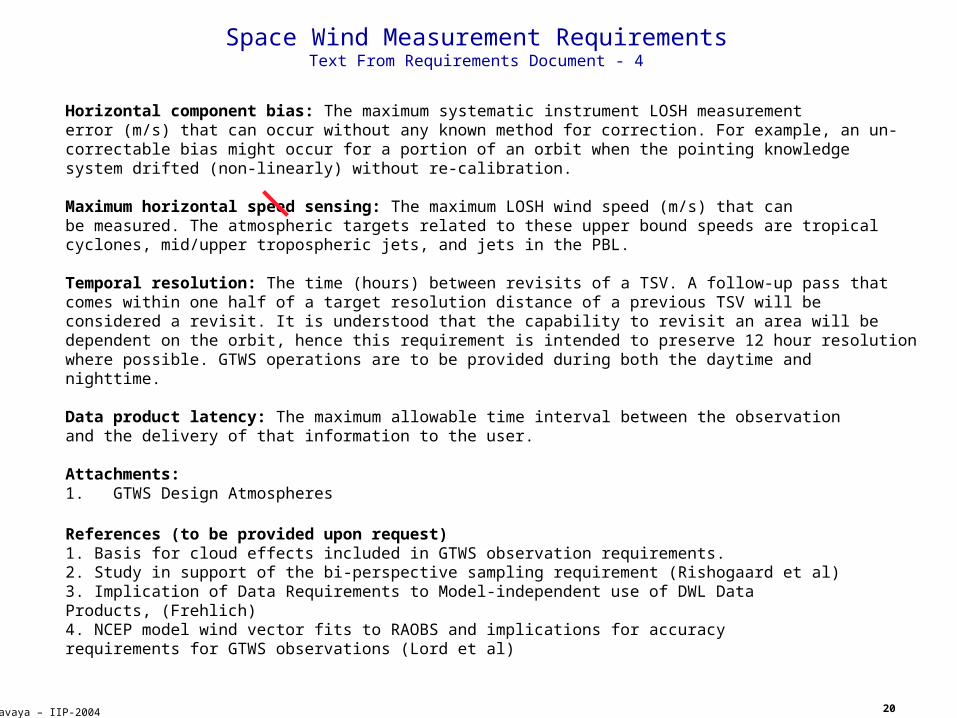
Horizontal component bias: The maximum systematic instrument LOSH measurementerror (m/s) that can occur without any known method for correction. For example, an un-correctable bias might occur for a portion of an orbit when the pointing knowledgesystem drifted (non-linearly) without re-calibration.
Maximum horizontal speed sensing: The maximum LOSH wind speed (m/s) that canbe measured. The atmospheric targets related to these upper bound speeds are tropicalcyclones, mid/upper tropospheric jets, and jets in the PBL.
Temporal resolution: The time (hours) between revisits of a TSV. A follow-up pass thatcomes within one half of a target resolution distance of a previous TSV will beconsidered a revisit. It is understood that the capability to revisit an area will bedependent on the orbit, hence this requirement is intended to preserve 12 hour resolutionwhere possible. GTWS operations are to be provided during both the daytime andnighttime.
Data product latency: The maximum allowable time interval between the observationand the delivery of that information to the user.
Attachments:1. GTWS Design Atmospheres
References (to be provided upon request)1. Basis for cloud effects included in GTWS observation requirements.2. Study in support of the bi-perspective sampling requirement (Rishogaard et al)3. Implication of Data Requirements to Model-independent use of DWL DataProducts, (Frehlich)4. NCEP model wind vector fits to RAOBS and implications for accuracyrequirements for GTWS observations (Lord et al)
21
Kavaya – IIP-2004
Space Wind Measurement RequirementsText From Requirements Document - 5
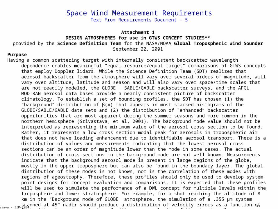
Attachment 1DESIGN ATMOSPHERES for use in GTWS CONCEPT STUDIES**
provided by the Science Definition Team for the NASA/NOAA Global Tropospheric Wind SounderSeptember 22, 2001
PurposeHaving a common scattering target with internally consistent backscatter wavelength
dependence enables meaningful "equal resource/equal target“ comparisons of GTWS concepts that employ Doppler lidars. While the Science Definition Team (SDT) realizes that aerosol backscatter from the atmosphere will vary over several orders of magnitude, will vary over altitude, latitude and season and will also vary over space/time scales that are not readily modeled, the GLOBE , SABLE/GABLE backscatter surveys, and the AFGL MODTRAN aerosol data bases provide a nearly consistent picture of backscatter climatology. To establish a set of bounding profiles, the SDT has chosen (1) the "background" distribution of β(π) that appears in most stacked histograms of the GLOBE/SABLE/GABLE data sets and (2) the distribution of "enhanced“ backscatter opportunities that are most apparent during the summer seasons and more common in the northern hemisphere (Srivastava, et al, 2001). The background mode value should not be interpreted as representing the minimum value of the aerosol cross section to be found. Rather, it represents a low cross section modal peak for aerosols in tropospheric air that does not have loading enhancement due to identifiable aerosol transport. There is a distribution of values and measurements indicating that the lowest aerosol cross sections can be an order of magnitude lower than the mode in some cases. The actual distribution of cross sections in the background mode are not well known. Measurements indicate that the background aerosol mode is present in large regions of the globe, mostly in the upper troposphere but can also be found in the boundary layer. The global distribution of these modes is not known, nor is the correlation of these modes with regions of ageostrophy. Therefore, these profiles should only be used to develop system point designs for concept evaluation and comparisons. It is expected that these profiles will be used to simulate the performance of a DWL concept for multiple levels within the troposphere and lower stratosphere. For example, for a shot reaching the altitude of 8 km in the “Background mode of GLOBE” atmosphere, the simulation of a .355 µm system scanned at 45° nadir should produce a distribution of velocity errors as a function of β(π) with a 2-way transmission of .498, a mean velocity of 25 m-1 s-1, a layer mean shear of 15.0 E-3 s-1, and a "shot scale" turbulence with a standard deviation of 3.5 m s-1. The distribution would be for the "background" aerosol mode that has a geometric mean of 4.4 E-8 m-1 sr-1 and a width of ln(s) = .8. A complete description of the point design including the energy/pulse, prf, integration time, mirror diameter, etc. should accompany any presentation of the simulated results. The effort to provide common reference atmospheres is on-going. Suggestion for improving these profiles and/or their application should becommunicated to the co-chairs of the SDT ([email protected] or [email protected] ). References Srivastava, V. , J. Rothermel, A. D. Clarke, J. D. Spinhirne, R.T. Menzies, D.R. Cutten, M.A. Jarzembski, D.A. Bowdle, and E.W. McCaul, 2001: Wavelength dependence of backscatter by use of aerosol microphysics and lidar data sets: application to 2.1um wavelength for space-based and airborne lidars. Applied Optics, V40, 4759-4769.
22
Kavaya – IIP-2004
Space Wind Measurement RequirementsText From Requirements Document - 6
Kavayats1. These atmospheres are meant only for the purpose of enabling "equal
target" comparisons of different DWL concepts and their potential LOS data products. Emphasis is on measurement accuracy and not representativeness or coverage. Furthermore, there is no claim to the frequency of occurrence of the two backscatter modes.
2. The wavelength dependency of the backscatter coefficient across the 1-2 orders of magnitude width of the background mode is thought to vary from λ-3 on the left side (lower on the left side (lower β) to λ-1.5 on the right side (higher on the right side (higher β)). A λ-2.5 was used in these tables going from 1.06 µm data to 2.0518 and .355 µm at and above 3 km. Since a different λ coefficient was used below 3 km, some smoothing of the resulting profiles has been done to make the transition more realistic. Even so, there are some “jumps” between the mid-troposphere and boundary layer values due in part to the use of different phase functions for the aerosol attenuation in those two regions.
3. Issues related to sampling and averaging (or co-processing) within regions of realistic wind variability are not addressed with these reference atmospheres. Significant differences will result from different scanning patterns and laser shot densities.
DefinitionsWavelength: expressed in micro-meters. Number in () is the line (cm-1) used
in FASCODE.Background mode: based upon GLOBE data representing the "background“ aerosol
mode found in both northern and southern hemisphere data sets.Enhanced mode: based upon GLOBE data taken during periods when aerosol
backscatter was clearly enhanced over the background cases. Enhancementincludes effects of elevated dust layers, convective pumping, biomass
burning, etc.MODTRAN: based upon the atmospheric transmission data for a maritime
tropical airmass with 50km visibility and 23km visibility in the boundary layer.
Trans(2x): two way transmission from space (nadir looking) to the bottom of the layer and back (units: fraction)
23
Kavaya – IIP-2004
Space Wind Measurement RequirementsText From Requirements Document - 7
Altitude: taken to be the top of the layer; data is assumed to be a point value for that altitude, except for surface wind which is taken to be at 10 m. For example the value of “B-back” = 0.490E-07 in the .355 tables (background mode) is to be interpreted as being at 3km. To obtain the average aerosol backscatter for the layer between 2 and 3 km, the value of 0.700E-07 at 2km should be used to compute the layer average of .595E-07. (units: km)
B-back: assumed to be the geometric mean of a lognormal distribution of GLOBE "background" aerosol mode data with ln(s) = .8 (units: m-1 sr-1). “s” is the distribution width.
B-enhan: values provided are the geometric layer mean of a lognormal distribution of the backscatter events that are in excess of the "background“ aerosol mode of backscatter, sometimes referred to as the convective mode. The width of this distribution is ln(s) = 1.0.
B-MOD: values of aerosol backscatter from MODTRAN data bases.Α-totl: total attenuation coefficient (aerosol scattering, aerosol
absorption, molecular scattering, molecular absorption) based on FASCODE (units: km-1).
M-back: molecular backscatter β(π) taken from MODTRAN (units: m-1 sr-1)U: based upon global averages from ECMWF T106 Nature Run; exception is the
jet superimposed at 10 km (units: m s-1)Sigma: "reasonable" values of uncorrelated wind variability on scales less
than 10 km (units: m s-1)Cld: clouds are expressed in terms of their optical depth (units: km-1). The
physical thickness is assumed to be 1 km (eg. cloud listed at 10km is located between 9 and 10km). The percent coverage of the Target Sample Volume(TSV) is taken to be 100% for the cloud between 9 and 10 km and 50% for the cloud between 2 and 3 km. The cloud between 2 and 3km is assumed to be composed of scattered small clouds that have horizontal dimensions equal to the spacing between individual lidar shots. Thus each shot has the same probability of being terminated by a cloud.
A-ext: aerosol extinction coefficient derived using the same backscatter/extinction ratios as those used in MODTRAN (units: km-1)
M-scat: attenuation due to molecular scattering (units: km-1)M-abs: attenuation due to molecular absorption (units: km-1)Trans(2x): two way transmission from space (nadir looking) to the bottom of
the layer and back (units: fraction)
24
Kavaya – IIP-2004
Space Wind Measurement RequirementsText From Requirements Document - 8
Wavelength: 2.0518 ( 4873.77)Background mode of GLOBE
z(km) B-back A-totl M-back U Sigma Cld A-ext M-scat M-abs Trans(2x)25. 0.256E-09 0.909E-05 0.233E-09 15. 1. 0.00 0.516E-05 0.198E-05 0.196E-05 0.100E+0124. 0.387E-09 0.123E-04 0.275E-09 15. 1. 0.00 0.780E-05 0.234E-05 0.216E-05 0.100E+0123. 0.587E-09 0.170E-04 0.323E-09 15. 1. 0.00 0.118E-04 0.274E-05 0.243E-05 0.100E+0122. 0.822E-09 0.227E-04 0.377E-09 15. 1. 0.00 0.166E-04 0.320E-05 0.294E-05 0.100E+0121. 0.984E-09 0.269E-04 0.442E-09 15. 1. 0.00 0.198E-04 0.376E-05 0.331E-05 0.100E+0120. 0.115E-08 0.317E-04 0.519E-09 15. 1. 0.00 0.232E-04 0.441E-05 0.413E-05 0.100E+0119. 0.114E-08 0.370E-04 0.609E-09 15. 1. 0.00 0.230E-04 0.518E-05 0.888E-05 0.100E+0118. 0.102E-08 0.428E-04 0.715E-09 15. 1. 0.00 0.206E-04 0.607E-05 0.161E-04 0.100E+0117. 0.831E-09 0.520E-04 0.844E-09 15. 1. 0.00 0.167E-04 0.717E-05 0.281E-04 0.999E+0016. 0.747E-09 0.790E-04 0.984E-09 15. 1. 0.00 0.150E-04 0.836E-05 0.556E-04 0.999E+0015. 0.773E-09 0.170E-03 0.115E-08 18. 1. 0.00 0.156E-04 0.981E-05 0.145E-03 0.999E+0014. 0.867E-09 0.385E-03 0.136E-08 22. 1. 0.00 0.175E-04 0.115E-04 0.356E-03 0.998E+0013. 0.700E-09 0.475E-03 0.159E-08 26. 1. 0.00 0.143E-04 0.135E-04 0.447E-03 0.997E+0012. 0.620E-09 0.754E-03 0.180E-08 28. 2. 0.00 0.130E-04 0.153E-04 0.725E-03 0.996E+0011. 0.590E-09 0.110E-02 0.203E-08 35. 5. 0.00 0.126E-04 0.172E-04 0.107E-02 0.994E+0010. 0.550E-09 0.155E-02 0.228E-08 50. 10. 0.14 0.123E-04 0.194E-04 0.152E-02 0.991E+009. 0.540E-09 0.222E-02 0.256E-08 40. 5. 0.00 0.316E-04 0.218E-04 0.216E-02 0.986E+008. 0.530E-09 0.302E-02 0.286E-08 25. 2. 0.00 0.440E-04 0.243E-04 0.295E-02 0.980E+007. 0.510E-09 0.409E-02 0.319E-08 18. 1. 0.00 0.667E-04 0.271E-04 0.400E-02 0.972E+006. 0.450E-09 0.525E-02 0.356E-08 16. 1. 0.00 0.770E-04 0.302E-04 0.515E-02 0.962E+005. 0.440E-09 0.715E-02 0.395E-08 14. 1. 0.00 0.897E-04 0.336E-04 0.703E-02 0.948E+004. 0.510E-09 0.920E-02 0.439E-08 13. 1. 0.00 0.167E-03 0.373E-04 0.900E-02 0.931E+003. 0.560E-09 0.240E-01 0.485E-08 12. 1. 5.00 0.300E-03 0.412E-04 0.236E-01 0.887E+002. 0.350E-08 0.184E-01 0.537E-08 11. 1. 0.00 0.818E-03 0.456E-04 0.175E-01 0.855E+001. 0.250E-07 0.340E-01 0.592E-08 10. 2. 0.00 0.236E-02 0.503E-04 0.315E-01 0.799E+000. 0.500E-07 0.492E-01 0.656E-08 2. 1. 0.00 0.432E-02 0.557E-04 0.448E-01 0.724E+00
25
Kavaya – IIP-2004
Space Wind Measurement RequirementsText From Requirements Document - 9
Wavelength: 2.0518 ( 4873.77)Enhanced mode of GLOBE
z(km) B-back A-totl M-back U Sigma Cld A-ext M-scat M-abs Trans(2x)25. 0.256E-09 0.909E-05 0.233E-09 15. 1. 0.00 0.516E-05 0.198E-05 0.196E-05 0.100E+0124. 0.387E-09 0.123E-04 0.275E-09 15. 1. 0.00 0.780E-05 0.234E-05 0.216E-05 0.100E+0123. 0.587E-09 0.170E-04 0.323E-09 15. 1. 0.00 0.118E-04 0.274E-05 0.243E-05 0.100E+0122. 0.822E-09 0.227E-04 0.377E-09 15. 1. 0.00 0.166E-04 0.320E-05 0.294E-05 0.100E+0121. 0.984E-09 0.269E-04 0.442E-09 15. 1. 0.00 0.198E-04 0.376E-05 0.331E-05 0.100E+0120. 0.115E-08 0.317E-04 0.519E-09 15. 1. 0.00 0.232E-04 0.441E-05 0.413E-05 0.100E+0119. 0.114E-08 0.370E-04 0.609E-09 15. 1. 0.00 0.230E-04 0.518E-05 0.888E-05 0.100E+0118. 0.102E-08 0.428E-04 0.715E-09 15. 1. 0.00 0.206E-04 0.607E-05 0.161E-04 0.100E+0117. 0.831E-09 0.520E-04 0.844E-09 15. 1. 0.00 0.167E-04 0.717E-05 0.281E-04 0.999E+0016. 0.747E-09 0.790E-04 0.984E-09 15. 1. 0.00 0.150E-04 0.836E-05 0.556E-04 0.999E+0015. 0.773E-09 0.170E-03 0.115E-08 18. 1. 0.00 0.156E-04 0.981E-05 0.145E-03 0.999E+0014. 0.867E-09 0.385E-03 0.136E-08 22. 1. 0.00 0.175E-04 0.115E-04 0.356E-03 0.998E+0013. 0.700E-09 0.475E-03 0.159E-08 26. 1. 0.00 0.143E-04 0.135E-04 0.447E-03 0.997E+0012. 0.280E-08 0.796E-03 0.180E-08 28. 2. 0.00 0.553E-04 0.153E-04 0.725E-03 0.996E+0011. 0.480E-08 0.118E-02 0.203E-08 35. 5. 0.00 0.943E-04 0.172E-04 0.107E-02 0.993E+0010. 0.150E-07 0.183E-02 0.228E-08 50. 10. 0.14 0.293E-03 0.194E-04 0.152E-02 0.990E+009. 0.160E-07 0.270E-02 0.256E-08 40. 5. 0.00 0.512E-03 0.218E-04 0.216E-02 0.984E+008. 0.180E-07 0.356E-02 0.286E-08 25. 2. 0.00 0.587E-03 0.243E-04 0.295E-02 0.977E+007. 0.210E-07 0.473E-02 0.319E-08 18. 1. 0.00 0.704E-03 0.271E-04 0.400E-02 0.968E+006. 0.250E-07 0.602E-02 0.356E-08 16. 1. 0.00 0.840E-03 0.302E-04 0.515E-02 0.957E+005. 0.290E-07 0.804E-02 0.395E-08 14. 1. 0.00 0.978E-03 0.336E-04 0.703E-02 0.941E+004. 0.300E-07 0.101E-01 0.439E-08 13. 1. 0.00 0.108E-02 0.373E-04 0.900E-02 0.923E+003. 0.280E-07 0.248E-01 0.485E-08 12. 1. 5.00 0.115E-02 0.412E-04 0.236E-01 0.878E+002. 0.300E-07 0.198E-01 0.537E-08 11. 1. 0.00 0.226E-02 0.456E-04 0.175E-01 0.844E+001. 0.250E-06 0.462E-01 0.592E-08 10. 2. 0.00 0.146E-01 0.503E-04 0.315E-01 0.769E+000. 0.500E-06 0.737E-01 0.656E-08 2. 1. 0.00 0.288E-01 0.557E-04 0.448E-01 0.664E+00
26
Kavaya – IIP-2004
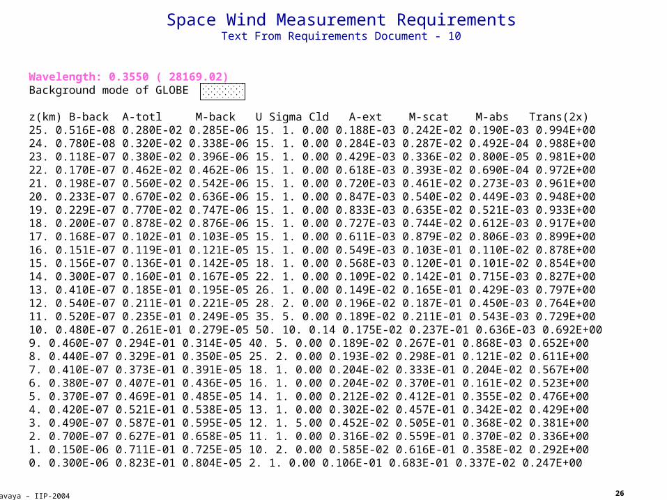
Space Wind Measurement RequirementsText From Requirements Document - 10
Wavelength: 0.3550 ( 28169.02)Background mode of GLOBE
z(km) B-back A-totl M-back U Sigma Cld A-ext M-scat M-abs Trans(2x)25. 0.516E-08 0.280E-02 0.285E-06 15. 1. 0.00 0.188E-03 0.242E-02 0.190E-03 0.994E+0024. 0.780E-08 0.320E-02 0.338E-06 15. 1. 0.00 0.284E-03 0.287E-02 0.492E-04 0.988E+0023. 0.118E-07 0.380E-02 0.396E-06 15. 1. 0.00 0.429E-03 0.336E-02 0.800E-05 0.981E+0022. 0.170E-07 0.462E-02 0.462E-06 15. 1. 0.00 0.618E-03 0.393E-02 0.690E-04 0.972E+0021. 0.198E-07 0.560E-02 0.542E-06 15. 1. 0.00 0.720E-03 0.461E-02 0.273E-03 0.961E+0020. 0.233E-07 0.670E-02 0.636E-06 15. 1. 0.00 0.847E-03 0.540E-02 0.449E-03 0.948E+0019. 0.229E-07 0.770E-02 0.747E-06 15. 1. 0.00 0.833E-03 0.635E-02 0.521E-03 0.933E+0018. 0.200E-07 0.878E-02 0.876E-06 15. 1. 0.00 0.727E-03 0.744E-02 0.612E-03 0.917E+0017. 0.168E-07 0.102E-01 0.103E-05 15. 1. 0.00 0.611E-03 0.879E-02 0.806E-03 0.899E+0016. 0.151E-07 0.119E-01 0.121E-05 15. 1. 0.00 0.549E-03 0.103E-01 0.110E-02 0.878E+0015. 0.156E-07 0.136E-01 0.142E-05 18. 1. 0.00 0.568E-03 0.120E-01 0.101E-02 0.854E+0014. 0.300E-07 0.160E-01 0.167E-05 22. 1. 0.00 0.109E-02 0.142E-01 0.715E-03 0.827E+0013. 0.410E-07 0.185E-01 0.195E-05 26. 1. 0.00 0.149E-02 0.165E-01 0.429E-03 0.797E+0012. 0.540E-07 0.211E-01 0.221E-05 28. 2. 0.00 0.196E-02 0.187E-01 0.450E-03 0.764E+0011. 0.520E-07 0.235E-01 0.249E-05 35. 5. 0.00 0.189E-02 0.211E-01 0.543E-03 0.729E+0010. 0.480E-07 0.261E-01 0.279E-05 50. 10. 0.14 0.175E-02 0.237E-01 0.636E-03 0.692E+009. 0.460E-07 0.294E-01 0.314E-05 40. 5. 0.00 0.189E-02 0.267E-01 0.868E-03 0.652E+008. 0.440E-07 0.329E-01 0.350E-05 25. 2. 0.00 0.193E-02 0.298E-01 0.121E-02 0.611E+007. 0.410E-07 0.373E-01 0.391E-05 18. 1. 0.00 0.204E-02 0.333E-01 0.204E-02 0.567E+006. 0.380E-07 0.407E-01 0.436E-05 16. 1. 0.00 0.204E-02 0.370E-01 0.161E-02 0.523E+005. 0.370E-07 0.469E-01 0.485E-05 14. 1. 0.00 0.212E-02 0.412E-01 0.355E-02 0.476E+004. 0.420E-07 0.521E-01 0.538E-05 13. 1. 0.00 0.302E-02 0.457E-01 0.342E-02 0.429E+003. 0.490E-07 0.587E-01 0.595E-05 12. 1. 5.00 0.452E-02 0.505E-01 0.368E-02 0.381E+002. 0.700E-07 0.627E-01 0.658E-05 11. 1. 0.00 0.316E-02 0.559E-01 0.370E-02 0.336E+001. 0.150E-06 0.711E-01 0.725E-05 10. 2. 0.00 0.585E-02 0.616E-01 0.358E-02 0.292E+000. 0.300E-06 0.823E-01 0.804E-05 2. 1. 0.00 0.106E-01 0.683E-01 0.337E-02 0.247E+00
27
Kavaya – IIP-2004
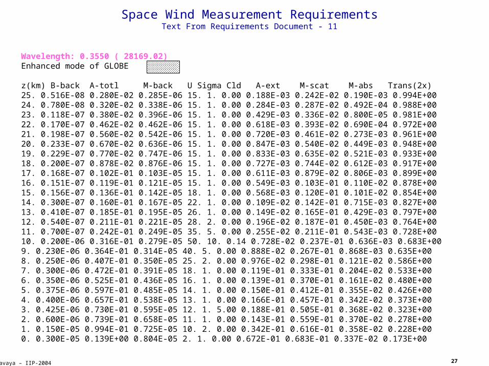
Space Wind Measurement RequirementsText From Requirements Document - 11
Wavelength: 0.3550 ( 28169.02)Enhanced mode of GLOBE
z(km) B-back A-totl M-back U Sigma Cld A-ext M-scat M-abs Trans(2x)25. 0.516E-08 0.280E-02 0.285E-06 15. 1. 0.00 0.188E-03 0.242E-02 0.190E-03 0.994E+0024. 0.780E-08 0.320E-02 0.338E-06 15. 1. 0.00 0.284E-03 0.287E-02 0.492E-04 0.988E+0023. 0.118E-07 0.380E-02 0.396E-06 15. 1. 0.00 0.429E-03 0.336E-02 0.800E-05 0.981E+0022. 0.170E-07 0.462E-02 0.462E-06 15. 1. 0.00 0.618E-03 0.393E-02 0.690E-04 0.972E+0021. 0.198E-07 0.560E-02 0.542E-06 15. 1. 0.00 0.720E-03 0.461E-02 0.273E-03 0.961E+0020. 0.233E-07 0.670E-02 0.636E-06 15. 1. 0.00 0.847E-03 0.540E-02 0.449E-03 0.948E+0019. 0.229E-07 0.770E-02 0.747E-06 15. 1. 0.00 0.833E-03 0.635E-02 0.521E-03 0.933E+0018. 0.200E-07 0.878E-02 0.876E-06 15. 1. 0.00 0.727E-03 0.744E-02 0.612E-03 0.917E+0017. 0.168E-07 0.102E-01 0.103E-05 15. 1. 0.00 0.611E-03 0.879E-02 0.806E-03 0.899E+0016. 0.151E-07 0.119E-01 0.121E-05 15. 1. 0.00 0.549E-03 0.103E-01 0.110E-02 0.878E+0015. 0.156E-07 0.136E-01 0.142E-05 18. 1. 0.00 0.568E-03 0.120E-01 0.101E-02 0.854E+0014. 0.300E-07 0.160E-01 0.167E-05 22. 1. 0.00 0.109E-02 0.142E-01 0.715E-03 0.827E+0013. 0.410E-07 0.185E-01 0.195E-05 26. 1. 0.00 0.149E-02 0.165E-01 0.429E-03 0.797E+0012. 0.540E-07 0.211E-01 0.221E-05 28. 2. 0.00 0.196E-02 0.187E-01 0.450E-03 0.764E+0011. 0.700E-07 0.242E-01 0.249E-05 35. 5. 0.00 0.255E-02 0.211E-01 0.543E-03 0.728E+0010. 0.200E-06 0.316E-01 0.279E-05 50. 10. 0.14 0.728E-02 0.237E-01 0.636E-03 0.683E+009. 0.230E-06 0.364E-01 0.314E-05 40. 5. 0.00 0.888E-02 0.267E-01 0.868E-03 0.635E+008. 0.250E-06 0.407E-01 0.350E-05 25. 2. 0.00 0.976E-02 0.298E-01 0.121E-02 0.586E+007. 0.300E-06 0.472E-01 0.391E-05 18. 1. 0.00 0.119E-01 0.333E-01 0.204E-02 0.533E+006. 0.350E-06 0.525E-01 0.436E-05 16. 1. 0.00 0.139E-01 0.370E-01 0.161E-02 0.480E+005. 0.375E-06 0.597E-01 0.485E-05 14. 1. 0.00 0.150E-01 0.412E-01 0.355E-02 0.426E+004. 0.400E-06 0.657E-01 0.538E-05 13. 1. 0.00 0.166E-01 0.457E-01 0.342E-02 0.373E+003. 0.425E-06 0.730E-01 0.595E-05 12. 1. 5.00 0.188E-01 0.505E-01 0.368E-02 0.323E+002. 0.600E-06 0.739E-01 0.658E-05 11. 1. 0.00 0.143E-01 0.559E-01 0.370E-02 0.278E+001. 0.150E-05 0.994E-01 0.725E-05 10. 2. 0.00 0.342E-01 0.616E-01 0.358E-02 0.228E+000. 0.300E-05 0.139E+00 0.804E-05 2. 1. 0.00 0.672E-01 0.683E-01 0.337E-02 0.173E+00
28
Kavaya – IIP-2004
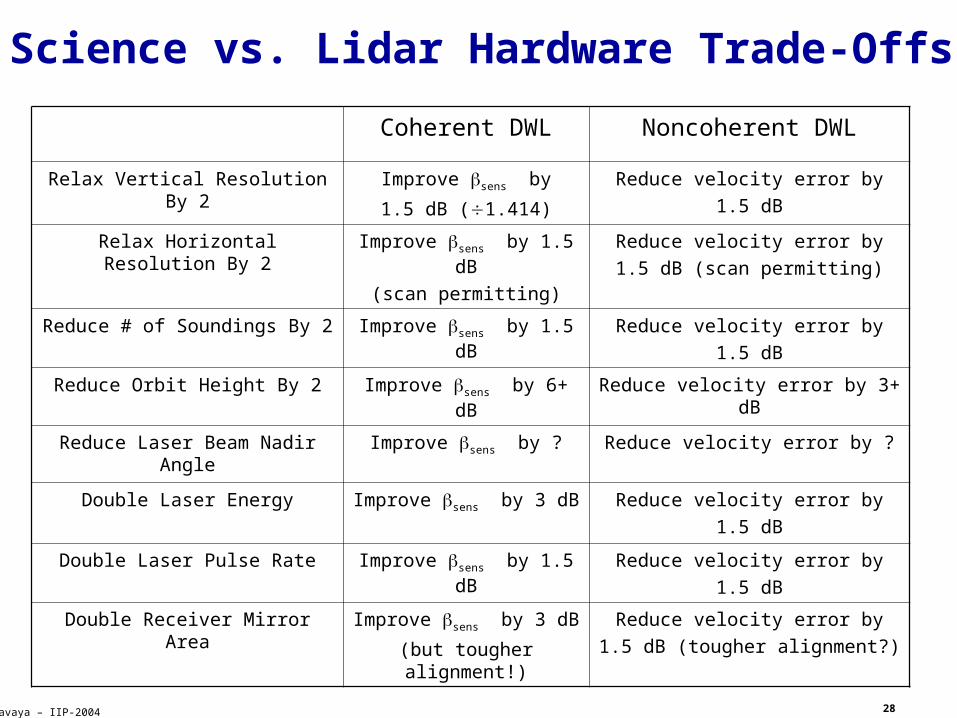
Science vs. Lidar Hardware Trade-Offs
Coherent DWL Noncoherent DWL
Relax Vertical Resolution By 2 Improve sens by
1.5 dB (1.414)
Reduce velocity error by
1.5 dB
Relax Horizontal Resolution By 2 Improve sens by 1.5 dB
(scan permitting)
Reduce velocity error by
1.5 dB (scan permitting)
Reduce # of Soundings By 2 Improve sens by 1.5 dB Reduce velocity error by
1.5 dB
Reduce Orbit Height By 2 Improve sens by 6+ dB Reduce velocity error by 3+ dB
Reduce Laser Beam Nadir Angle Improve sens by ? Reduce velocity error by ?
Double Laser Energy Improve sens by 3 dB Reduce velocity error by
1.5 dB
Double Laser Pulse Rate Improve sens by 1.5 dB Reduce velocity error by
1.5 dB
Double Receiver Mirror Area Improve sens by 3 dB
(but tougher alignment!)
Reduce velocity error by
1.5 dB (tougher alignment?)