Embed Size (px)
Citation preview

Getting Started - 1
1 - Introduction
Thank you for purchasing the E-MU 1616 or E-MU 1616M digital audio system. We’ve designed your E-MU Digital Audio System to be logical, intuitive and above all, to provide you with pristine sound quality. Both systems provide true studio-quality, 24-bit/192kHz multi-channel recording and playback at a truly astounding price.
System Requirements
• Genuine Intel
®
Pentium
®
III, AMD
®
K6
®
class processor operating at 500 MHz or faster• Intel, AMD or 100% compatible motherboard & chipset• Windows 2000 SP4, or Windows XP SP1• 256 MB RAM• 500 MB of free hard disk space for full installation.• Available CardBus (type 2) compliant slot• XVGA Video (1024 x 768)• CD-ROM drive required for software installation.• Headphones or amplified speakers
Other applications may have higher system requirements or may require a microphone.
Package Contents
E-MU 1616 E-MU 1616M
• E-MU 02 CardBus card• MicroDock• +48VDC AC Adapter• EDI (E-MU Digital Interface) cable• MIDI Breakout Cable• E-MU Digital Audio System Software/Driver Install CD-ROM• Production Tools Software Bundle CD-ROM• This Quick Start guide
• E-MU 02 CardBus card• MIcroDock M
(Mastering-grade converters)
• +48VDC AC Adapter• EDI (E-MU Digital Interface) cable• MIDI Breakout Cable• E-MU Digital Audio System Software/Driver Install CD-ROM• Production Tools Software Bundle CD-ROM• This Quick Start guide
Mana GS.fm Page 1 Thursday, March 10, 2005 2:59 PM

2 - E-MU Digital Audio System
2 - Hardware Installation
The E-MU 02 CardBus Card
The E-MU 02 CardBus card is the heart of the system and contains E-MU’s powerful E-DSP chip. The powerful hardware DSP on this little card leaves more CPU power free on your computer for additional software plug-ins and other tasks.
CardBus Connector
Connects the E-MU 02 CardBus card to your computer.
Removing the CardBus Card
Before removing the CardBus card, you need to select “Safely Remove Hardware” from the Taskbar. Otherwise ASIO channels will remain allocated to the Digital Audio System and your other audio applications may develop problems or hang.
1. From the Taskbar, select the icon. The “Safely Remove Hardware” pop-up window appears.
2. Choose OK, then press the Eject button on the CardBus slot to eject the card.
Monitor Output
This output is designed to drive stereo headphones or any line-level input. Adjust the monitor output level in the PatchMix DSP application to control the volume of this output.
EDI ConnectorConnect to MicroDock
Monitor OutputLine Level or Headphones
CardBus ConnectorConnect to Computer
E-MU 02 CardBus Card
Mana GS.fm Page 2 Thursday, March 10, 2005 2:59 PM
Getting Started - 3
Connecting the MicroDock to the 02 CardBus Card
Connect the supplied EDI cable from the RJ-45 jack on the E-MU 02 CardBus card labeled “EDI” to the matching connector labeled “EDI” on the MicroDock.The cable type is a standard CAT 5e network cable which is specially shielded to prevent RF emissions. Contact E-MU Systems if you need a replacement cable.
CAUTION:
Do not connect the MicroDock or 02 CardBus Card to Ethernet or network connectors. Doing so may result in permanent damage to either your computer, the E-MU hardware or both.
Supplying Power to the MicroDock
The MicroDock is powered from the supplied +48VDC Adapter. Connect the Adapter to the jack marked +48VDC on the back panel of the MicroDock. Turn the MicroDock on by turning the Headphone Volume control up.
EDI
48 VDC+ -
+48V DC Adapter
02 CardBus CardThe Headphone Volume Control is also the Power Switch.
Important - Read Before InstallationIf you are currently using the Creative Audigy 2 ZS Notebook Sound Blaster, you should UNINSTALL the Creative software and drivers from your PC BEFORE installing the E-MU drivers. Once the E-MU drivers have been success-fully installed, you should be able to reinstall the Audigy 2 ZS drivers if desired.
Mana GS.fm Page 3 Thursday, March 10, 2005 2:59 PM

4 - E-MU Digital Audio System
3 - Software Installation
Installing and Uninstalling the Digital Audio System Drivers and Applications
Install the Patchmix DSP software and drivers the first time you restart your PC after installing the E-MU 02 CardBus card.
Windows 2000 or Windows XP
(The software is not compatible with other versions of Windows.)
1. After you have installed the 02 CardBus card, turn on your computer. Windows automatically detects the audio card and searches for device drivers.
2. When prompted by the New Hardware Wizard for the audio drivers, click the
Cancel
button. 3. Insert the E-MU software Installation CD into your CD-ROM drive. If Windows AutoPlay mode is enabled for your
CD-ROM drive, the CD starts running automatically. If not, from your Windows desktop, click
Start
->
Run
and type
d:\setup.exe
(replace
d:\
with the drive letter of your CD-ROM drive). You can also simply open the CD and double-click
setup.exe
.4. The installation splash screen appears. Follow the instructions on the screen to complete the installation. 5. Choose “Continue Anyway” when you encounter the “Windows Logo Testing” warning screen.6. When prompted, restart your computer.
Uninstalling all Audio Drivers and Applications
At times you may need to uninstall or reinstall some or all of the audio card's applications and device drivers to correct problems, change configurations, or upgrade outdated drivers or applications. Before you begin, close all audio card applications. Applications still running during the uninstallation will not be removed.
1. Click
Start
->
Settings
->
Control Panel
. 2. Double-click the
Add/Remove Programs
icon. 3. Click the
Install/Uninstall
tab (or
Change or Remove Programs
button).4. Select the
E-MU 1616
entry and then click the
Change/Remove
button.5. In the
InstallShield Wizard
dialog box, select the
Remove ALL
option.6. Click the
Yes
button. 7. Restart your computer when prompted.8. You may now re-install existing or updated E-MU 02 CardBus card device drivers or applications.
Mana GS.fm Page 4 Thursday, March 10, 2005 2:59 PM
Getting Started - 5
4 - Connections
EDI
In
1L 1R 2L 2R
3L 3R2L 2R
Out
1L 1R
PhonoGnd2L 2R
1 2Out
48 VDC+ -
MIDI Cable
3
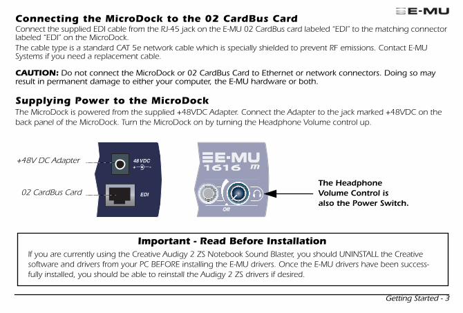
BasicConnections Turntable
* *
MIDI 1
MIDI In
MIDI Out
PoweredDesktopSpeakers
MIDI Synthesizer
Mixer&
Speakers
Audiofrom
Synthesizer
Audioto
Monitors
ConnectDesktop
Speakers to1/8" jacks
CardBusCard
AC Adapter
Stereo
In
Out
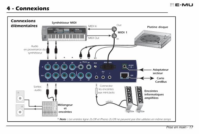
* Note: Line Inputs 2L/2R and Phono 2L/2R cannot be used at the same time.
Mana GS.fm Page 5 Thursday, March 10, 2005 2:59 PM
6 - E-MU Digital Audio System
LineA Mic
-15 0
Line -Mic -
Clip
+50
LineB Mic
+65-15 0
48V
+50+65
S/PDIF
In Out
-3-6
-12-20
SL
Clip -3-6
-12-20
SL
Off
Instrument
Mic
StereoHeadphones
On/Off& Phone Volume
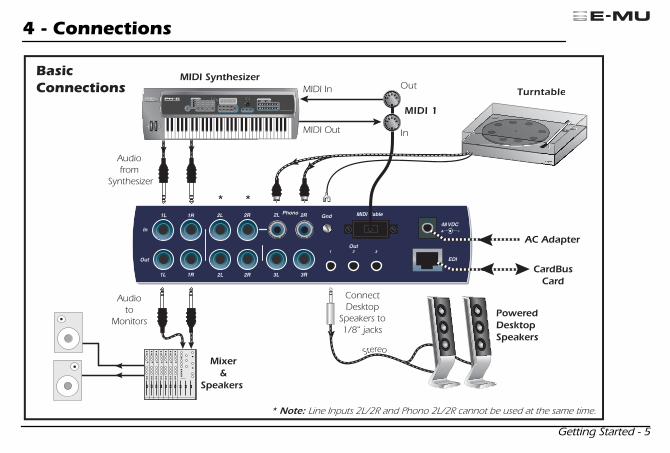
Front PanelAnalog Connections
Use the centerPhone Jack for
High Impedanceinstruments suchas electric guitar
or bass.
Use the 3-pin XLR jackfor Low Impedance
microphones.
Mana GS.fm Page 6 Thursday, March 10, 2005 2:59 PM
Getting Started - 7
MIDI 1
S/PDIF(Coax)
ADAT(Optical)
MIDI Keyboard
EMULATOR
P R E S E T
S A M P L E
S E Q U E N C E R
P A G E
L E V E L
P R E S E T S E L E C T
R E A L T I M E C O N T R O L L E R SA S S I G N A B L E K E Y S
E N T E RE X I T
R E T U R N
0 .987654321
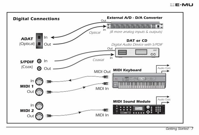
Digital Connections
DAT or CDDigital Audio Device with S/PDIF
(8 more analog inputs & outputs)
Coaxial
Optical
I
VOLUME
O
TRANSPOSE DIGITAL PROCESSINGSAMPLE MANAGEMENT
SAMPLE
PRESET
MASTER/GLOBAL
MULTIMODE PRESET MANAGEMENT DYNAMIC PROCESINGPRESET DEFINITION
DRIVE SELECT LOAD SAVE AUDITION TRIGGER MODEESCAPE
MIDI
ENTER
DEC/NO
INC/YES ABC
JKL
TUV
DEF
MNO
WXY
QZ
GHI
PRS
TRIGGERS
1 2 3
4 5 6
7 8 9
0
MIDI Sound Module
In
Out
In
MIDI 2Out
In
MIDI Out
In
In
Out
Out
MIDI In
Out
In
Out
MIDI In
1 2 3 4 5 6 7 8
External A/D - D/A Converter
Audio Outs
Audio Outs
Mana GS.fm Page 7 Thursday, March 10, 2005 2:59 PM
8 - E-MU Digital Audio System
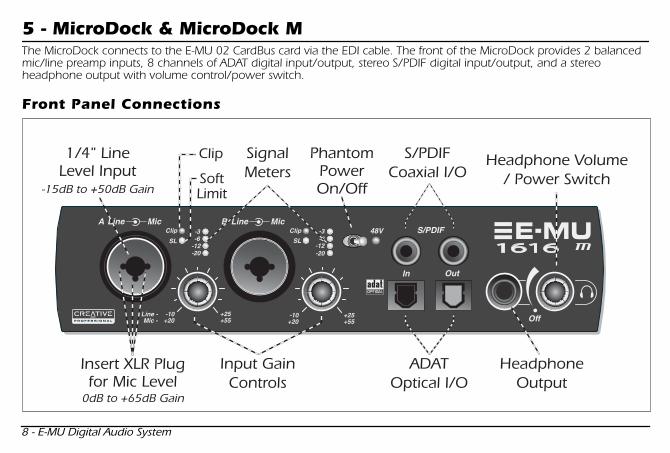
5 - MicroDock & MicroDock M
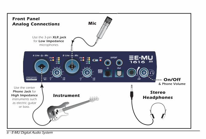
The MicroDock connects to the E-MU 02 CardBus card via the EDI cable. The front of the MicroDock provides 2 balanced mic/line preamp inputs, 8 channels of ADAT digital input/output, stereo S/PDIF digital input/output, and a stereo headphone output with volume control/power switch.
Front Panel Connections
LineA Mic
-10+20
Line -Mic -
Clip
+25
LineB Mic
+55-10+20
48V
+25+55
S/PDIF
In Out
-3-6
-12-20
SL
Clip -3-6
-12-20
SL
Off
1/4" LineLevel Input
PhantomPowerOn/Off
SignalMeters
Clip
SoftLimit
Input GainControls
HeadphoneOutput
Headphone Volume/ Power Switch
S/PDIFCoaxial I/O
ADATOptical I/O
Insert XLR Plugfor Mic Level
0dB to +65dB Gain
-15dB to +50dB Gain
Mana GS.fm Page 8 Thursday, March 10, 2005 2:59 PM
Getting Started - 9
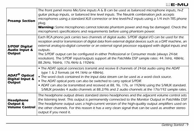
Preamp Section
The front panel mono Mic/Line inputs A & B can be used as balanced microphone inputs, hi-Z guitar pickup inputs, or balanced line level inputs. The Neutrik combination jack accepts microphones using a standard XLR connector or line level/hi-Z inputs using a 1/4 inch TRS phone plug.
Warning:
Some microphones cannot tolerate phantom power and may be damaged. Check the microphone’s specifications and requirements before using phantom power.
S/PDIF Digital Audio Input & Output
Each RCA phono jack carries two channels of digital audio. S/PDIF digital I/O can be used for the reception and/or transmission of digital data from external digital devices such as a DAT machine, an external analog-to-digital converter or an external signal processor equipped with digital inputs and outputs. The S/PDIF output can be configured in either Professional or Consumer mode (always 24-bit resolution). The S/PDIF input/outputs support all the PatchMix DSP sample rates: 44.1kHz, 48kHz, 88.2kHz, 96kHz, 176.4kHz & 192kHz.
ADAT
®
Optical Digital Input & Output
• The ADAT optical connectors transmit and receive 8 channels of 24-bit audio using the ADAT type 1 & 2 formats (at 44.1kHz or 48kHz).
• The word clock contained in the input data stream can be used as a word clock source. • The ADAT optical ports can also be switched to carry optical S/PDIF.• ADAT can also be transmitted and received at 88, 96, 176, or 192kHz using the S/MUX standard.
S/MUX provides 4 audio channels at 88.2/96 and 2 audio channels at the 176/192 sample rates.
Headphone Output & Volume Control
The headphone output drives standard stereo headphones and the adjacent volume control sets the listening level. This output is permanently connected to the Monitor Output in PatchMix DSP.The headphone output uses a high-current version of the high-quality output amplifiers used on the other channels. For this reason it has a very clean signal that can be used as another stereo output if you need it.
Mana GS.fm Page 9 Thursday, March 10, 2005 2:59 PM
10 - E-MU Digital Audio System
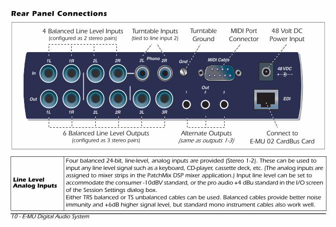
Rear Panel Connections
Line Level Analog Inputs
Four balanced 24-bit, line-level, analog inputs are provided (Stereo 1-2). These can be used to input any line level signal such as a keyboard, CD-player, cassette deck, etc. (The analog inputs are assigned to mixer strips in the PatchMix DSP mixer application.) Input line level can be set to accommodate the consumer -10dBV standard, or the pro audio +4 dBu standard in the I/O screen of the Session Settings dialog box. Either TRS balanced or TS unbalanced cables can be used. Balanced cables provide better noise immunity and +6dB higher signal level, but standard mono instrument cables also work well.
EDI
In
1L 1R 2L 2R
3L 3R2L 2R
Out
1L 1R
PhonoGnd2L 2R
1 2Out
48 VDC+ -
MIDI Cable
3
4 Balanced Line Level Inputs(configured as 2 stereo pairs)
Turntable Inputs(tied to line input 2)
TurntableGround
Alternate Outputs6 Balanced Line Level Outputs(configured as 3 stereo pairs)
MIDI PortConnector
48 Volt DCPower Input
Connect toE-MU 02 CardBus Card(same as outputs 1-3)
Mana GS.fm Page 10 Thursday, March 10, 2005 2:59 PM
Getting Started - 11
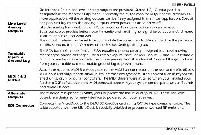
Line Level Analog Outputs
Six balanced 24-bit, line-level, analog outputs are provided (Stereo 1-3). Output pair 1 is designated as the Monitor Output and is normally fed by the monitor output of the PatchMix DSP mixer application. All the analog outputs can be freely assigned in the mixer application. Special anti-pop circuitry mutes the analog outputs when power is turned on or off. Like the analog line inputs, either TRS balanced or TS unbalanced cables can be used. Balanced cables provide better noise immunity and +6dB higher signal level, but standard mono instrument cables also work well. The output line level can be set to accommodate the consumer -10dBV standard, or the pro audio +4 dBu standard in the I/O screen of the Session Settings dialog box.
Turntable Inputs & Ground Lug
The RCA turntable inputs feed an RIAA equalized phono preamp designed to accept moving magnet type phono cartridges. The turntable inputs share line level inputs 2L and 2R. Inserting a plug into Line Input 2 disconnects the phono preamp from that channel. Connect the ground lead from your turntable to the turntable ground lug to prevent hum.
MIDI 1& 2 In/Out
Attach the supplied MIDI Breakout cable to the MIDI Port connector on the rear of the MicroDock.MIDI input and output ports allow you to interface any type of MIDI equipment such as keyboards, effect units, drum or guitar controllers. The MIDI drivers were installed when you installed your Patchmix DSP software and the MIDI ports will appear in your system control panel under “Sounds and Audio Devices”.
AlternateOutputs
These stereo mini-phone (3.5mm) jacks duplicate the line level outputs 1-3. These line level outputs are designed for easy interface to powered computer speakers.
EDI Connector
Connects the MicroDock to the E-MU 02 CardBus card using CAT 5e type computer cable. The cable supplied with the MicroDock is specially shielded to prevent unwanted RF emissions.
Mana GS.fm Page 11 Thursday, March 10, 2005 2:59 PM
12 - E-MU Digital Audio System
Getting More Information
The
“Product Default”
Session is automatically loaded on boot-up and has all the inputs and outputs assigned to ASIO channels. However, you must configure your audio recording applications to use
“E-MU ASIO”
.
Please refer to the various online Help files and the Owner’s Manual (on CD) for detailed information on the E-MU Digital Audio System and various software applications. See: “Program Files -> Creative Professional -> E-MU 1616 Documents”
Technical Support
As the E-MU Digital Audio System expands, you’ll want to keep up with the latest software and new options for your E-MU Digital Audio System. You can find all of this—plus other helpful information—at
www.emu.com
. Refer to your Owner’s Manual PDF on the supplied CD for the technical support phone number.
Information in this document is subject to change without notice and does not represent a commitment on the part of E-MU Systems, Inc. No part of this manual may be reproduced or transmitted in any form or by any means, electronic or mechanical, including photocopying and recording, for any purpose without the written permission of E-MU Systems, Inc. The software described in this document is furnished under a license agreement and may be used or copied only in accor-dance with the terms of the license agreement. It is against the law to copy the software on any other medium except as specifically allowed in the license agreement. The licensee may make one copy of the software for backup purposes only. E-MU is a registered trademark of E-MU Systems, Inc. in the United States and/or other countries.
Copyright © 2005 by E-MU Systems, Inc. All rights reserved. Version 1.00 April 2005
Warning
Handling the cord(s) on this product may expose you to lead, a chemical known to the State of California to cause cancer or birth defects or other reproductive harm. Wash hands after handling.
Mana GS.fm Page 12 Thursday, March 10, 2005 2:59 PM

Prise en main - 13
1 - Introduction
Merci d’avoir choisi le système audionumérique E-MU 1616 ou E-MU 1616M. Nous avons conçu ce système E-MU afin qu’il soit logique et intuitif et qu’il vous offre une qualité sonore irréprochable. Les deux systèmes offrent une qualité professionnelle, un enregistrement et une lecture multipiste 24 bits/192 kHz pour un prix incroyablement réduit.
Système requis
• Processeurs Intel
®
Pentium
®
III, AMD
®
K6
®
à 500 MHz ou plus rapides• Puce et carte mère Intel, AMD ou 100 % compatible• Windows 2000 SP4, ou Windows XP SP1• 256 Mo de RAM• 500 Mo d’espace libre sur le disque dur pour la totalité de l’installation• Port compatible CardBus (type 2)• Vidéo XVGA (1024 x 768)• Lecteur de CD-ROM pour l’installation logicielle• Casque ou enceintes amplifiées
Certaines applications peuvent nécessiter une configuration plus puissante ou l’utilisation d’un micro.
Contenu
E-MU 1616 E-MU 1616M
• Carte CardBus E-MU 02• MicroDock• Adaptateur secteur +48 Vcc• Câble EDI (E-MU Digital Interface)• Câble MIDI spécial• CD d’installation et d’application• Mode d’emploi (sur le CD)• Ce guide de prise en main
• Carte CardBus E-MU 02• MIcroDock M
(convertisseurs de Mastering)
• Adaptateur secteur +48 Vcc• Câble EDI (E-MU Digital Interface)• Câble MIDI spécial• CD d’installation et d’application• Mode d’emploi (sur le CD)• Ce guide de prise en main
French Mana GS.fm Page 13 Thursday, March 10, 2005 3:04 PM

14 - Système audionumérique E-MU
2 - Installation matérielle
Carte CardBus E-MU 02
La carte CardBus E-MU 02 est au coeur du système et contient la puissante puce E-DSP d’E-MU. Le DSP de cette carte compacte libère le processeur de votre ordinateur pour vos Plug-ins et autres tâches.
Connecteur CardBus
Connecte la carte CardBus E-MU 02 à votre ordinateur.
Retrait de la carte CardBus
Avant de retirer la carte CardBus, vous devez sélectionner “Safely Remove Hardware” (retrait du périphérique) dans la barre de tâche. Sinon les canaux ASIO restent alloués au système Emu et vos autres applications audio risquent de planter.
1. Dans la barre de tâches, sélectionnez l’icône . La fenêtre “Safely Remove Hardware” s’affiche.
2. Sélectionnez OK et appuyez sur Eject sur le port CardBus pour éjecter la carte.
Sortie écoute
Cette sortie a été conçue pour alimenter un casque stéréo ou une entrée stéréo ligne. Réglez le niveau de sortie dans PatchMix DSP.
Connecteur EDIVers MicroDock
Sortie d’écouteNiveau ligne ou casque
Connecteur CardBusvers l’ordinateur
Carte CardBus E-MU 02
French Mana GS.fm Page 14 Thursday, March 10, 2005 3:04 PM
Prise en main - 15
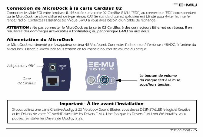
Connexion de MicroDock à la carte CardBus 02
Connectez le câble EDI entre l’embase RJ-45 située sur la carte 02 CardBus E-MU (“EDI”) au connecteur “EDI” correspondant sur le MicroDock. Le câble utilisé est de type réseau CAT 5e standard qui est spécialement blindé pour éviter les interfé-rences radio. Contactez l’assistance technique E-MU si vous avez besoin d’un câble de rechange.
ATTENTION :
Ne pas connecter le MicroDock ou la carte 02 CardBus à des connecteurs Ethernet ou réseau. Il en résulterait des dommages irréversibles à l’ordinateur, au périphérique E-MU ou aux deux.
Alimentation du MicroDock
Le MicroDock est alimenté par l’adaptateur secteur 48 Vcc fourni. Connectez l’adaptateur à l’embase +48VDC, à l’arrière du MicroDock. Placez le MicroDock sous tension en tournant le bouton de volume du casque.
Adaptateur +48V
Carte 02 CardBus
Le bouton de volume du casque sert à la mise sous/hors tension.
Important - À lire avant l’installationSi vous utilisez une carte Creative Audigy 2 ZS Notebook Sound Blaster, vous devez DÉSINSTALLER le logiciel Creative et les Drivers de votre PC AVANT d’installer les Drivers E-MU. Une fois que les Drivers E-MU ont été installés, vous pouvez réinstaller les Drivers de l’Audigy 2 ZS.
French Mana GS.fm Page 15 Thursday, March 10, 2005 3:04 PM
16 - Système audionumérique E-MU
3 - Installation logicielle
Installation/désinstallation des Drivers et applications Digital Audio System
Installez Patchmix DSP et les Drivers lors du premier démarrage de votre PC après l’installation de la carte E-MU 02 CardBus.
Windows 2000 ou Windows XP
(Le logiciel n’est pas compatible avec d’autres versions de Windows).
1. Après avoir installé la carte 02 CardBus, allumez l’ordinateur. Windows détecte la carte audio et recherche les Drivers du périphérique.
2. Lorsque l’écran Assistant d’installation d’un nouveau périphérique vous demande de sélectionner le Driver audio, cliquez sur
Annuler
. 3. Insérez le CD d’installation E-MU dans le lecteur de CD-ROM. Si le mode automatique de Windows est activé pour
le lecteur de CD-ROM, le CD démarre. Sinon, dans Windows, cliquez sur
Démarrer
->
Exécuter
et saisissez
d:\setup.exe
(
d:\
est la lettre de votre lecteur de CD-ROM), ou ouvrez le CD et double-cliquez sur
setup.exe
.4. L’écran d’installation s’affiche. Suivez les instructions à l’écran pour terminer l’installation. 5. Sélectionnez “Continuer quand même” lorsque l’écran “Test de logo Windows” s’affiche.6. Lorsque l’ordinateur vous le demande, redémarrez.
Désinstallation de tous les Drivers audio et de toutes les applications
Vous pourrez être amené à désinstaller ou réinstaller les applications et Drivers de la carte son afin de corriger des problèmes, modifier des configurations ou pour mettre à jour les Drivers ou applications. Avant de commencer, fermez toutes les applications de la carte son. Les applications qui tournent lors de la désinstallation ne sont pas supprimées.
1. Cliquez sur
Démarrer -> Paramètres -> Panneau de configuration
. 2. Double-cliquez sur l’icône
Ajout/Suppression de programmes
. 3. Cliquez sur l’onglet
Installer/Désinstaller
(ou sur le bouton
Modifier/Supprimer
des programmes).4. Sélectionnez
E-MU 1616
puis cliquez sur Modifier
/Supprimer
.5. Dans la fenêtre
InstallShield Wizard
sélectionnez l’option
Tout supprimer
.6. Cliquez sur le bouton
Oui
. 7. À l'invite, redémarrez votre ordinateur.8. Vous pouvez réinstaller les Drivers ou les applications de la carte E-MU 02 CardBus existants ou mis à jour.
French Mana GS.fm Page 16 Thursday, March 10, 2005 3:04 PM
Prise en main - 17
4 - Connexions
French Mana GS.fm Page 17 Thursday, March 10, 2005 3:04 PM
18 - Système audionumérique E-MU
French Mana GS.fm Page 18 Thursday, March 10, 2005 3:04 PM

Prise en main - 19
French Mana GS.fm Page 19 Thursday, March 10, 2005 3:04 PM
20 - Système audionumérique E-MU
5 - MicroDock et MicroDock M
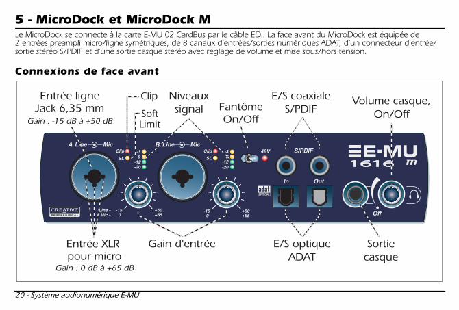
Le MicroDock se connecte à la carte E-MU 02 CardBus par le câble EDI. La face avant du MicroDock est équipée de 2 entrées préampli micro/ligne symétriques, de 8 canaux d’entrées/sorties numériques ADAT, d’un connecteur d’entrée/sortie stéréo S/PDIF et d’une sortie casque stéréo avec réglage de volume et mise sous/hors tension.
Connexions de face avant
French Mana GS.fm Page 20 Thursday, March 10, 2005 3:04 PM

Prise en main - 21
Section préampli
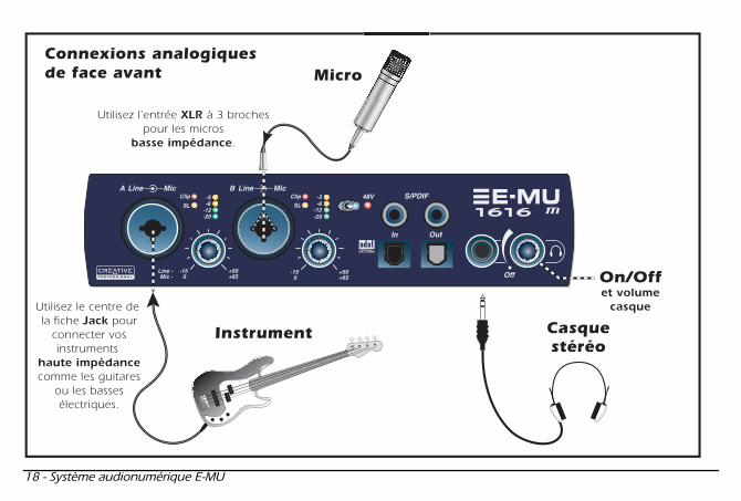
Les entrées mono Mic/Line A et B de face avant peuvent être utilisées comme entrées micro symétriques, comme entrées guitare haute impédance, ou comme entrées ligne symétriques. Les connecteurs combinés Neutrik acceptent des connecteurs standards XLR ou des Jacks 6,35 mm stéréo ou mono à niveau ligne ou haute impédance (guitare).
Attention :
Certains micros peuvent être endommagés par l’alimentation fantôme. Consultez le mode d’emploi du micro avant d’utiliser l’alimentation fantôme.
Entrées/sorties audio-numériques S/PDIF
Chaque connecteur RCA dispose de deux canaux pour le son numérique. L’entrée et la sortie numérique S/PDIF peuvent être utilisées pour la réception et/ou la transmission de données numériques en provenance d’appareils numériques tels qu’un enregistreur, un convertisseur analogique/numérique externe ou un processeur externe avec entrées et sorties numériques.La sortie S/PDIF peut être configurée au format professionnel ou grand public (toujours en 24-bits). les entrées/sorties S/PDIF sont compatibles avec les fréquences d’échantillonnage de 44,1kHz, 48 kHz, 96 kHz et 192 kHz.
Entrée/sortie numérique optique ADAT
®
• Les connecteurs optiques ADAT transmettent et reçoivent les informations sur 8 canaux à 24-bits aux formats ADAT 1 et 2 (à 44,1 kHz ou 48 kHz).
• Les données Wordclock reçues en entrée peuvent être utilisées comme source d’horloge. • Les ports optiques ADAT peuvent également porter un signal optique au format S/PDIF.• Les données ADAT peuvent être reçues et transmises à 96 kHz ou 192 kHz au format S/MUX.
Le format S/MUX offre 4 canaux audio à 96 kHz et 2 canaux audio à 192 kHz.
Sortie casque et réglage de volume
La sortie casque permet la connexion de casques stéréo standards. Le bouton de volume détermine le niveau d’écoute. Cette sortie est connectée de façon permanente à la sortie Monitor Output de PatchMix DSP.La sortie casque utilise une version à fort courant des sorties amplifiées des autres canaux. Pour cette raison, le son est très propre et elle peut être utilisée comme sortie ligne stéréo.
French Mana GS.fm Page 21 Thursday, March 10, 2005 3:04 PM
22 - Système audionumérique E-MU
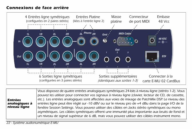
Connexions de face arrière
Entréesanalogiques à niveau ligne
Vous disposez de quatre entrées analogiques symétriques 24-bits à niveau ligne (stéréo 1-2). Vous pouvez les utiliser pour connecter vos signaux à niveau ligne (clavier, lecteur de CD, de cassette, etc.). Les entrées analogiques sont affectées aux voies de mixage de PatchMix DSP. Le niveau des entrées ligne peut être réglé sur -10 dBV ou sur le niveau pro de +4 dBu dans la page I/O de la fenêtre Session Settings. Vous pouvez utiliser des câbles en Jacks stéréo symétriques ou mono asymétriques. Les câbles symétriques offrent une immunité plus importante aux bruits de fond et un niveau de signal supérieur de 6 dB, mais vous pouvez utiliser des câbles instrument mono.
French Mana GS.fm Page 22 Thursday, March 10, 2005 3:04 PM

Prise en main - 23
Sorties analogiques à niveau ligne
Vous disposez de six sorties analogiques symétriques 24-bits à niveau ligne (Stereo 1-3). La paire de sorties 1 sert de sortie Monitor Out. Elle est en général alimentée par la sortie Monitor du mélangeur de PatchMix DSP. Toutes les sorties analogiques peuvent être librement affectées dans l’application de mixage. Une temporisation spéciale coupe ces sorties lors de la mise sous tension pour éviter les bruits de pop. Comme pour les entrées ligne analogiques, vous pouvez utiliser des câbles en Jacks symétriques ou asymétriques. Les câbles symétriques offrent une immunité plus importante aux bruits de fond et un niveau de signal supérieur de 6 dB, mais vous pouvez utiliser des câbles instrument mono. Le niveau des sorties ligne peut être réglé sur -10 dBV ou sur le niveau pro de +4 dBu dans la page I/O de la fenêtre Session Settings
Entrée platine et plot de masse
Les entrées platine en RCA alimentent un préamplificateur RIAA conçu pour accepter les cellules phono magnétiques. Les entrées Phono utilisent les mêmes circuits que les entrées ligne 2L et 2R. Insérez un connecteur dans l’entrée ligne 2 pour déconnecter l’entrée Phono. Connectez le fil de masse de votre platine au plot de masse pour éviter les ronflements.
E/S MIDI 1et 2
Connectez le câble MIDI spécial fourni à l’embase MIDI située en face arrière du MicroDock.Les ports d’entrée et de sortie MIDI vous permettent d’utiliser tout type d’appareils MIDI comme les claviers, les processeurs d’effets, les boîtes à rythmes, ou les guitares MIDI. Les Drivers MIDI ont été installés lors de l’installation de Patchmix DSP. Les ports MIDI s’affichent dans le panneau de contrôle de votre système dans “Sons et périphériques audio”.
Sortiessupplémentaires
Ces mini-Jacks stéréo (3,5 mm) reprennent les signaux des sorties ligne 1-3. Ces sorties à niveau ligne ont été conçues pour permettre la connexion directe à vos enceintes informatiques amplifiées.
Connecteur EDI
Connecte le MicroDock à la carte 02 CardBus E-MU à l’aide du câble CAT 5e. Le câble fourni avec le MicroDock est spécialement blindé pour éviter toute émission HF parasite (interférences).
French Mana GS.fm Page 23 Thursday, March 10, 2005 3:04 PM

24 - Système audionumérique E-MU
Informations supplémentaires
La session
“Product Default”
est automatiquement chargée lors du démarrage avec toutes les entrées et sorties assignées aux voies ASIO. Cependant, vous devez configurer votre application d’enregistrement audio pour utiliser
“E-MU ASIO”
. Prenez le temps de consulter les divers fichiers d’aide en ligne (Help) et le mode d’emploi (sur le CD) pour obtenir de plus amples informations sur le système audionumérique E-MU et les diverses applications. Voir : “Program Files -> Creative Professional -> E-MU 1616 Documents”
Assistance technique
Vous pouvez vous assurer de la mise à jour de votre système audionumérique E-MU en consultant le site Internet
www.emu.com
. Vous y trouverez également de très nombreuses informations très utiles.Consultez le PDF du mode d’emploi sur le CD fourni pour obtenir le numéro de téléphone de l’assistance technique.
Les informations divulguées dans ce document sont sujettes à modification sans préavis et n’engagent aucune responsa-bilité de la part d’E-MU Systems, Inc. Interdiction de reproduire ou de transmettre ce document de façon électronique ou mécanique (ce qui comprend la photocopie et l’enregistrement) sans l’autorisation écrite d’E-MU Systems, Inc. Le logiciel décrit dans ce document est fourni avec un accord de licence que vous devez accepter. Il ne peut être utilisé ou copié que selon les termes de l’accord de licence. Il est illégal de copier le logiciel sur un autre support, excepté tel qu’autorisé spécifi-quement dans l’accord de licence. Le détenteur de la licence peut effectuer une copie du logiciel à des fins de sauvegarde uniquement. E-MU est une marque déposée d’E-MU Systems, Inc. aux USA et dans d’autres pays. Copyright © 2005 par E-MU Systems, Inc. Tous droits réservés. Version 1.00 Mars 2005
Mise en garde
La manipulation des câbles de ce produit peut vous mettre en contact avec le plomb, un agent chimique connu en Californie comme cause de cancers, de malformations congénitales, ou autres problèmes. Lavez-vous les mains après toute manipulation.
French Mana GS.fm Page 24 Thursday, March 10, 2005 3:04 PM

Erste Schritte - 25
1 - Einleitung
Herzlichen Dank für den Kauf des E-MU 1616 oder E-MU 1616M Digitalaudio-Systems. Das E-MU Digital Audio System ist logisch, intuitiv und liefert vor allem eine erstklassige Klangqualität. Beide Systeme ermöglichen die Mehrkanalaufnahme und -wiedergabe mit 24-Bit/192kHz in echter Studioqualität zu einem wirklich erstaunlichen Preis.
Systemanforderungen
• Prozessor der Klasse Intel
®
Pentium
®
III, AMD
®
K6
®
mit 500 MHz oder schneller• Intel, AMD oder 100% kompatibles Motherboard & Chipsatz• Windows 2000 SP4 oder Windows XP SP1• 256 MB RAM• 500 MB freier Festplattenspeicher bei vollständiger Installation• CardBus (Typ 2) kompatibler Steckplatz• XVGA Video (1024 x 768)• CD-ROM Laufwerk für die Software-Installation• Kopfhörer oder Aktivboxen
Andere Anwendungen stellen möglicherweise höhere Systemanforderungen oder erfordern ein Mikrofon.
Lieferumfang
E-MU 1616 E-MU 1616M
• E-MU 02 CardBus Card• MicroDock• +48VDC AC-Adapter• EDI (E-MU Digital Interface) Kabel• MIDI Breakout-Kabel• Installations- und Anwendungs-CD• Bedienungshandbuch (auf CD)• Diese Schnellstart-Anleitung
• E-MU 02 CardBus Card• MIcroDock M (Konverter der Mastering-Stufe)• +48VDC AC-Adapter• EDI (E-MU Digital Interface) Kabel• MIDI Breakout-Kabel• Installations- und Anwendungs-CD• Bedienungshandbuch (auf CD)• Diese Schnellstart-Anleitung
Mana GS (DE).fm Page 25 Thursday, March 10, 2005 3:07 PM
26 - E-MU Digital Audio System
2 - Hardware-Installation
Die E-MU 02 CardBus Card
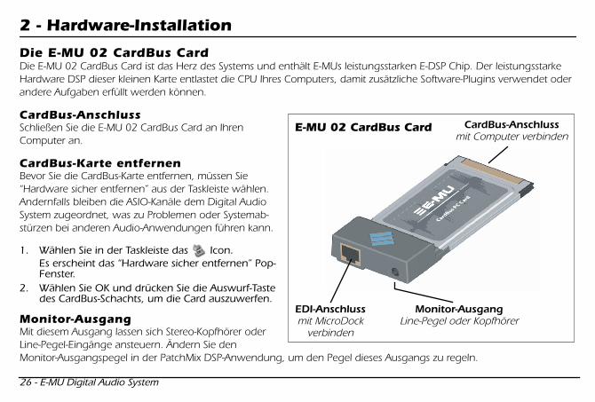
Die E-MU 02 CardBus Card ist das Herz des Systems und enthält E-MUs leistungsstarken E-DSP Chip. Der leistungsstarke Hardware DSP dieser kleinen Karte entlastet die CPU Ihres Computers, damit zusätzliche Software-Plugins verwendet oder andere Aufgaben erfüllt werden können.
CardBus-Anschluss
Schließen Sie die E-MU 02 CardBus Card an Ihren Computer an.
CardBus-Karte entfernen
Bevor Sie die CardBus-Karte entfernen, müssen Sie “Hardware sicher entfernen” aus der Taskleiste wählen. Andernfalls bleiben die ASIO-Kanäle dem Digital Audio System zugeordnet, was zu Problemen oder Systemab-stürzen bei anderen Audio-Anwendungen führen kann.
1. Wählen Sie in der Taskleiste das Icon. Es erscheint das “Hardware sicher entfernen” Pop-Fenster.
2. Wählen Sie OK und drücken Sie die Auswurf-Taste des CardBus-Schachts, um die Card auszuwerfen.
Monitor-Ausgang
Mit diesem Ausgang lassen sich Stereo-Kopfhörer oder Line-Pegel-Eingänge ansteuern. Ändern Sie den Monitor-Ausgangspegel in der PatchMix DSP-Anwendung, um den Pegel dieses Ausgangs zu regeln.
EDI-Anschlussmit MicroDock
verbinden
Monitor-AusgangLine-Pegel oder Kopfhörer
CardBus-Anschlussmit Computer verbinden
E-MU 02 CardBus Card
Mana GS (DE).fm Page 26 Thursday, March 10, 2005 3:07 PM
Erste Schritte - 27
MicroDock an die 02 CardBus Card anschließen
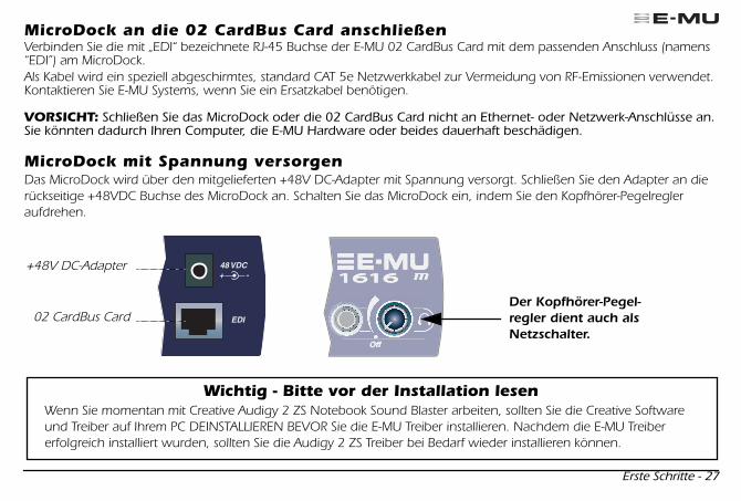
Verbinden Sie die mit „EDI“ bezeichnete RJ-45 Buchse der E-MU 02 CardBus Card mit dem passenden Anschluss (namens “EDI”) am MicroDock.Als Kabel wird ein speziell abgeschirmtes, standard CAT 5e Netzwerkkabel zur Vermeidung von RF-Emissionen verwendet. Kontaktieren Sie E-MU Systems, wenn Sie ein Ersatzkabel benötigen.
VORSICHT:
Schließen Sie das MicroDock oder die 02 CardBus Card nicht an Ethernet- oder Netzwerk-Anschlüsse an. Sie könnten dadurch Ihren Computer, die E-MU Hardware oder beides dauerhaft beschädigen.
MicroDock mit Spannung versorgen
Das MicroDock wird über den mitgelieferten +48V DC-Adapter mit Spannung versorgt. Schließen Sie den Adapter an die rückseitige +48VDC Buchse des MicroDock an. Schalten Sie das MicroDock ein, indem Sie den Kopfhörer-Pegelregler aufdrehen.
+48V DC-Adapter
02 CardBus CardDer Kopfhörer-Pegel-regler dient auch als Netzschalter.
Wichtig - Bitte vor der Installation lesenWenn Sie momentan mit Creative Audigy 2 ZS Notebook Sound Blaster arbeiten, sollten Sie die Creative Software und Treiber auf Ihrem PC DEINSTALLIEREN BEVOR Sie die E-MU Treiber installieren. Nachdem die E-MU Treiber erfolgreich installiert wurden, sollten Sie die Audigy 2 ZS Treiber bei Bedarf wieder installieren können.
Mana GS (DE).fm Page 27 Thursday, March 10, 2005 3:07 PM

28 - E-MU Digital Audio System
3 - Software-Installation
Digital Audio System-Treiber und -Anwendungen installieren/deinstallieren
Installieren Sie die Patchmix DSP Software und Treiber, sobald Sie die E-MU 02 CardBus Card installiert und Ihren PC neu gestartet haben.
Windows 2000 oder Windows XP
(Die Software ist mit anderen Windows-Versionen nicht kompatibel.)
1. Schalten Sie nach der Installation der 02 CardBus Card Ihren Computer ein. Windows erkennt automatisch die Audio-Card und sucht nach Geräte-Treibern.
2. Wenn Sie vom Hardware-Assistent nach Audio-Treibern gefragt werden, klicken Sie auf den
Cancel
Button. 3. Legen Sie die E-MU Software Installations-CD in Ihr CD-ROM Laufwerk ein. Wenn der Windows AutoPlay-Modus bei
Ihrem CD-ROM Laufwerk aktiviert ist, startet die CD automatisch. Andernfalls klicken Sie auf dem Windows Desktop auf
Start
->
Ausführen
und geben
d:\setup.exe
ein (
d:\
durch den Laufwerks-Buchstaben Ihres CD-ROM Laufwerks ersetzen). Sie können auch einfach das CD-Verzeichnis öffnen und auf
setup.exe
doppelklicken.4. Es erscheint der Start-Bildschirm der Installation. Gehen Sie nach den Anleitungen des Bildschirms vor, um die
Installation abzuschließen. 5. Klicken Sie auf “Fortfahren”, wenn die “Windows Logo Testing” Warnung erscheint.6. Starten Sie bei der entsprechenden Aufforderung Ihren Computer neu.
Alle Audio-Treiber und Anwendungen deinstallieren
Manchmal werden Sie einige oder alle Anwendungen und Geräte-Treiber der Audio Card de- oder neu installieren müssen, um Probleme zu lösen, Konfigurationen zu ändern oder veraltete Treiber und Anwendungen zu aktualisieren. Bevor Sie beginnen, sollten Sie alle Audio Card-Anwendungen schließen. Anwendungen, die bei der Deinstallation noch laufen, werden nicht entfernt.
1. Klicken Sie auf
Start
->
Einstellungen
->
Systemsteuerung
. 2. Doppelklicken Sie auf das Icon
Programme hinzufügen/entfernen
. 3. Klicken Sie auf das
Installieren/Deinstallieren
Register (oder den
Programme ändern/entfernen
Button).4. Wählen Sie den
E-MU 1616
Eintrag und klicken Sie auf den
Ändern/Entfernen
Button.5. In der
InstallShield Wizard
Dialogbox wählen Sie die Option
ALLES entfernen
.6. Klicken Sie auf den
Ja
Button. 7. Starten Sie bei der entsprechenden Aufforderung Ihren Computer neu.8. Jetzt können Sie bestehende oder aktualisierte Gerätetreiber oder Anwendungen für die E-MU 02 Card neu installieren.
Mana GS (DE).fm Page 28 Thursday, March 10, 2005 3:07 PM

Erste Schritte - 29
4 - Anschlüsse
EDI
In
1L 1R 2L 2R
3L 3R2L 2R
Out
1L 1R
PhonoGnd2L 2R
1 2Out
48 VDC+ -
MIDI Cable
3
ElementareAnschlüsse Plattenspieler
* *
MIDI 1
MIDI In
MIDI Out
Desktop-Aktivboxen
MIDI-Synthesizer
Mischer&
Boxen
Audiovom
Synthesizer
Audiozu den
Monitoren
Desktop-Boxen an
1/8" Buchsenanschließen
CardBusCard
AC-Adapter
Stereo
In
Out
* Hinweis: Die Line Inputs 2L/2R und Phono 2L/2R können nicht gleichzeitig benutzt werden.
Mana GS (DE).fm Page 29 Thursday, March 10, 2005 3:07 PM

30 - E-MU Digital Audio System
Mana GS (DE).fm Page 30 Thursday, March 10, 2005 3:07 PM
Erste Schritte - 31
Mana GS (DE).fm Page 31 Thursday, March 10, 2005 3:07 PM
32 - E-MU Digital Audio System
5 - MicroDock & MicroDock M
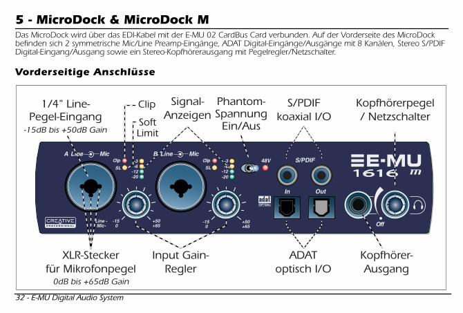
Das MicroDock wird über das EDI-Kabel mit der E-MU 02 CardBus Card verbunden. Auf der Vorderseite des MicroDock befinden sich 2 symmetrische Mic/Line Preamp-Eingänge, ADAT Digital-Eingänge/Ausgänge mit 8 Kanälen, Stereo S/PDIF Digital-Eingang/Ausgang sowie ein Stereo-Kopfhörerausgang mit Pegelregler/Netzschalter.
Vorderseitige Anschlüsse
Mana GS (DE).fm Page 32 Thursday, March 10, 2005 3:07 PM

Erste Schritte - 33
Preamp-Sektion
Die vorderseitigen Mono Mic/Line-Eingänge A & B sind als symmetrische Mikrofon-Eingänge, hochohmige Gitarren-Pickup-Eingänge oder symmetrische Line-Pegel-Eingänge einsetzbar. Die Neutrik-Kombibuchse akzeptiert Mikrofone mit standard XLR-Anschluss oder Line-Pegel/hochohmige Eingänge mit 1/4“ TRS-Klinkenstecker.
Warnung:
Manche Mikrofone können durch Phantomspannung beschädigt werden. Prüfen Sie vor dem Einsatz von Phantomspannung die Spezifikationen und Anforderungen des Mikrofons.
S/PDIF Digital- audio Eingang & Ausgang
Jeder Cinch-Stecker überträgt zwei Kanäle mit Digitalaudio. Der S/PDIF Digital I/O ist einsetzbar für den Empfang/die Übertragung von Digitaldaten von/zu externen Digitalgeräten, wie DAT Player, externer A/D-Konverter oder externer Signalprozessor mit Digital-Eingängen/Ausgängen.Der S/PDIF-Ausgang kann als Professional- oder Consumer-Modus (immer mit 24-Bit Auflösung) konfiguriert werden. Die S/PDIF Ein-/Ausgänge unterstützen die Sampleraten 44.1kHz, 48kHz, 96kHz & 192kHz.
ADAT
®
Optische Digital-Eingänge & Ausgänge
• Die optischen ADAT-Anschlüsse senden und empfangen 8 Kanäle mit 24-Bit Audio im ADAT Type 1 & 2 Format (bei 44.1kHz oder 48kHz).
• Die im Eingangs-Datenstrom enthaltene Word Clock kann als Word Clock-Quelle benutzt werden. • Die optischen ADAT-Ports können auch auf die Übertragung von optischem S/PDIF umgeschaltet
werden.• ADAT kann auch unter Verwendung des S/MUX Standards mit 96kHz oder 192kHz gesendet/
empfangen werden. S/MUX bietet 4 Audiokanäle bei 96kHz und 2 Audiokanäle bei 192kHz Samplerate.
Kopfhörer-ausgang & Pegelregler
Der Kopfhörerausgang eignet sich für standard Stereo-Kopfhörer und der benachbarte Pegelregler steuert den Abhörpegel. Dieser Ausgang ist fest mit dem Monitor Output in PatchMix DSP verbunden.Der Kopfhörer-Ausgang benutzt eine Hochspannungsversion der hochwertigen Ausgangs-verstärker der anderen Kanäle. Er liefert daher ein sehr sauberes Signal, das bei Bedarf als zusätzlicher Stereo-Ausgang einsetzbar ist.
Mana GS (DE).fm Page 33 Thursday, March 10, 2005 3:07 PM
34 - E-MU Digital Audio System
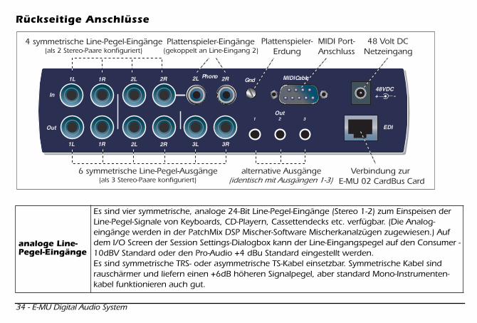
Rückseitige Anschlüsse
analoge Line-Pegel-Eingänge
Es sind vier symmetrische, analoge 24-Bit Line-Pegel-Eingänge (Stereo 1-2) zum Einspeisen der Line-Pegel-Signale von Keyboards, CD-Playern, Cassettendecks etc. verfügbar. (Die Analog-eingänge werden in der PatchMix DSP Mischer-Software Mischerkanalzügen zugewiesen.) Auf dem I/O Screen der Session Settings-Dialogbox kann der Line-Eingangspegel auf den Consumer -10dBV Standard oder den Pro-Audio +4 dBu Standard eingestellt werden. Es sind symmetrische TRS- oder asymmetrische TS-Kabel einsetzbar. Symmetrische Kabel sind rauschärmer und liefern einen +6dB höheren Signalpegel, aber standard Mono-Instrumenten-kabel funktionieren auch gut.
Mana GS (DE).fm Page 34 Thursday, March 10, 2005 3:07 PM
Erste Schritte - 35
analoge Line-Pegel-Ausgänge
Es sind sechs symmetrische, analoge 24-Bit Line-Pegel-Ausgänge (Stereo 1-3) verfügbar. Das Ausgangspaar 1 ist als Monitor-Ausgang konzipiert und wird normalerweise vom Monitor-Ausgang der PatchMix DSP Mischer-Software gespeist. Alle Analogausgänge sind in der Mischer-Applikation frei zuweisbar. Eine spezielle Antipop-Schaltung schaltet die Analogausgänge beim Ein-/Ausschalten des Geräts stumm. Wie bei den analogen Line-Eingängen sind symmetrische TRS- oder asymmetrische TS-Kabel verwendbar. Symmetrische Kabel sind rauschärmer und liefern einen +6dB höheren Signalpegel, aber standard Mono-Instrumentenkabel funktionieren auch gut. Auf dem I/O Screen der Session Settings-Dialogbox kann der Line-Ausgangspegel auf den Consumer -10dBV Standard oder den Pro-Audio +4 dBu Standard eingestellt werden.
Plattenspieler-Eingänge & Erdungs-anschluss
Die Plattenspieler-Cinch-Eingänge speisen einen RIAA entzerrten Phono-Preamp, der Drehmagnet-Phono-Tonabnehmer akzeptiert. Die Plattenspieler-Eingänge laufen über die Line-Pegel-Eingänge 2L und 2R. Wird ein Stecker an Line Input 2 angeschlossen, wird der Phono-Preamp von diesem Kanal getrennt. Verbinden Sie das Erdungskabel des Plattenspielers mit dem Plattenspieler-Erdungsanschluss, um Brummen zu vermeiden.
MIDI 1& 2 In/Out
Verbinden Sie das mitgelieferte MIDI Breakout-Kabel mit dem MIDI Port-Anschluss auf der Rückseite des MicroDock. Über die MIDI Ein- und Ausgangs-Ports können Sie alle MIDI-Geräte, z. B. Keyboards, Effektgeräte, Drum Machines oder Gitarren-Controller, integrieren. Die MIDI-Treiber wurden mit Ihrer Patchmix DSP Software installiert und die MIDI Ports erscheinen in der Systemsteuerung unter “Sounds und Audiogeräte”.
AlternativeAusgänge
Diese Stereo-Mini-Klinkenbuchsen (3.5 mm) duplizieren die Line-Pegel-Ausgänge 1-3 und sind für die einfache Verbindung mit Computer-Aktivboxen konzipiert.
EDI-Anschluss
Verbindet das MicroDock über ein CAT 5e Computerkabel mit der E-MU 02 CardBus Card. Das mit dem MicroDock gelieferte Kabel ist speziell abgeschirmt, um unerwünschte RF-Emissionen zu verhindern.
Mana GS (DE).fm Page 35 Thursday, March 10, 2005 3:07 PM
36 - E-MU Digital Audio System
Weitere Informationen
Beim Starten des Computers wird die
“Product Default”
Session automatisch geladen und alle Ein- und Ausgänge werden ASIO-Kanälen zugewiesen. Sie müssen Ihre Audio-Aufnahme-Software allerdings auf die Verwendung von
“E-MU ASIO”
konfigurieren
.
In den verschiedenen online Help-Dateien und im Bedienungshandbuch (auf CD) finden Sie detaillierte Infos zum E-MU Digital Audio System und verschiedenen Software-Applikationen. Siehe: “Program Files -> Creative Professional -> E-MU 1616 Documents”
Technischer Support
Da das E-MU Digital Audio System ständig erweitert wird, möchten Sie wahrscheinlich in puncto Software und neuen Optionen für Ihr E-MU Digital Audio System auf dem neuesten Stand bleiben. All dies — und weitere hilfreiche Infos — finden Sie unter
www.emu.com
. Die Telefonnummer des Technischen Supports finden Sie im PDF des Bedienungshandbuchs auf der mitgelieferten CD.Die Informationen dieses Handbuchs können ohne Ankündigung geändert werden und stellen keine Verpflichtung seitens E-MU Systems, Inc dar. Kein Teil dieses Handbuchs darf ohne die schriftliche Erlaubnis von E-MU Systems, Inc. in irgendeiner Form oder mit irgendwelchen Mitteln - elektronisch oder mechanisch, inklusive Photokopieren und Aufzeichnen – zu irgen-deinem Zweck reproduziert oder übertragen werden. Die in diesem Dokument beschriebene Software wird unter einem Lizenzvertrag geliefert und darf nur entsprechend den Bedingungen des Lizenzvertrags benutzt oder kopiert werden. Es ist gesetzeswidrig, die Software auf ein anderes Medium zu kopieren, falls dies im Lizenzvertrag nicht explizit erlaubt ist. Der Lizenznehmer darf eine Kopie der Software nur zu Sicherheitszwecken erstellen. E-MU ist eingetragenes Warenzeichen von E-MU Systems, Inc. in den USA und/oder anderen Ländern.
Copyright © 2005 E-MU Systems, Inc. Alle Rechte vorbehalten. Version 1.00 April 2005
Mana GS (DE).fm Page 36 Thursday, March 10, 2005 3:07 PM

Inicio rápido - 37
1 - Introducción
Felicidades y gracias por comprar el sistema audio digital E-MU 1616 o E-MU 1616M. Hemos diseñado este E-MU Digital Audio System para que sea lógico, intuitivo y, por encima de todo, para ofrecerle la máxima calidad de sonido. Ambos sistemas le ofrece una auténtica calidad de estudio y grabación y reproducción multicanal de 24 bits/192kHz a un precio verdaderamente increíble.
Requisitos del sistema
• Genuino procesador Intel
®
Pentium
®
III, AMD
®
K6
®
que funcione a una velocidad de 500 MHz o superior• Placa base y chipset Intel, AMD o 100% compatible• Sistema operativo Windows 2000 SP4 o Windows XP SP1• 256 MB de memoria RAM• 500 MB de espacio en el disco duro para la instalación completa.• Una ranura CardBus (tipo 2) disponible• Placa de vídeo XVGA (1024 x 768)• Unidad de CD-ROM para la instalación del software.• Auriculares o altavoces autoamplificados
Otros programas pueden necesitar requisitos del sistema superiores o el uso de un micrófono.
Elementos incluidos
E-MU 1616 E-MU 1616M
• Tarjeta CardBus E-MU 02• MicroDock• Adaptador AC +48 VDC• Cable EDI (Interface digital E-MU)• Cable de ruptura MIDI• CD de instalación de driver/software del Sistema de audio digital E-MU• CD con paquete de programas de herramientas de producción• Este manual de Inicio rápido
• Tarjeta CardBus E-MU 02• MIcroDock M
(convertidor de masterización)
• Adaptador AC +48 VDC• Cable EDI (Interface digital E-MU)• Cable de ruptura MIDI• CD de instalación de driver/software del
Sistema de audio digital E-MU• CD con paquete de programas de
herramientas de producción• Este manual de Inicio rápido
Spanish Mana.fm Page 37 Thursday, March 10, 2005 3:09 PM
38 - E-MU Digital Audio System
2 - Instalación del hardware
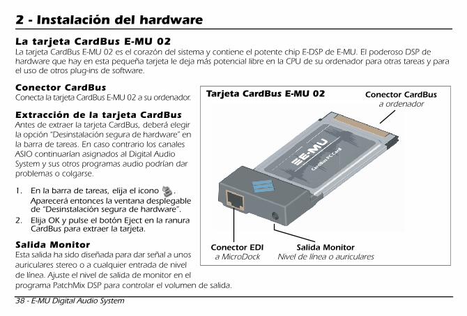
La tarjeta CardBus E-MU 02
La tarjeta CardBus E-MU 02 es el corazón del sistema y contiene el potente chip E-DSP de E-MU. El poderoso DSP de hardware que hay en esta pequeña tarjeta le deja más potencial libre en la CPU de su ordenador para otras tareas y para el uso de otros plug-ins de software.
Conector CardBus
Conecta la tarjeta CardBus E-MU 02 a su ordenador.
Extracción de la tarjeta CardBus
Antes de extraer la tarjeta CardBus, deberá elegir la opción “Desinstalación segura de hardware” en la barra de tareas. En caso contrario los canales ASIO continuarían asignados al Digital Audio System y sus otros programas audio podrían dar problemas o colgarse.
1. En la barra de tareas, elija el icono . Aparecerá entonces la ventana desplegable de “Desinstalación segura de hardware”.
2. Elija OK y pulse el botón Eject en la ranura CardBus para extraer la tarjeta.
Salida Monitor
Esta salida ha sido diseñada para dar señal a unos auriculares stereo o a cualquier entrada de nivel de línea. Ajuste el nivel de salida de monitor en el programa PatchMix DSP para controlar el volumen de salida.
Conector EDIa MicroDock
Salida MonitorNivel de línea o auriculares
Conector CardBusa ordenador
Tarjeta CardBus E-MU 02
Spanish Mana.fm Page 38 Thursday, March 10, 2005 3:09 PM
Inicio rápido - 39
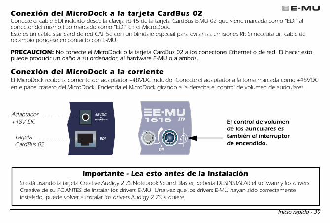
Conexión del MicroDock a la tarjeta CardBus 02
Conecte el cable EDI incluido desde la clavija RJ-45 de la tarjeta CardBus E-MU 02 que viene marcada como “EDI” al conector del mismo tipo marcado como “EDI” en el MicroDock.Este es un cable standard de red CAT 5e con un blindaje especial para evitar las emisiones RF. Si necesita un cable de recambio póngase en contacto con E-MU.
PRECAUCION:
No conecte el MicroDock o la tarjeta CardBus 02 a los conectores Ethernet o de red. El hacer esto puede producir un daño a su ordenador, al hardware E-MU o a ambos.
Conexión del MicroDock a la corriente
El MicroDock recibe la corriente del adaptador +48VDC incluido. Conecte el adaptador a la toma marcada como +48VDC en e panel trasero del MicroDock. Encienda el MicroDock girando a la derecha el control de volumen de auriculares.
Adaptador +48V DC
Tarjeta CardBus 02
El control de volumen de los auriculares es también el interruptorde encendido.
Importante - Lea esto antes de la instalaciónSi está usando la tarjeta Creative Audigy 2 ZS Notebook Sound Blaster, debería DESINSTALAR el software y los drivers Creative de su PC ANTES de instalar los drivers E-MU. Una vez que los drivers E-MU hayan sido correctamente instalado, puede volver a instalar los drivers Audigy 2 ZS si quiere.
Spanish Mana.fm Page 39 Thursday, March 10, 2005 3:09 PM
40 - E-MU Digital Audio System
3 - Instalación de software
Instalación y desinstalación de los Drivers y Aplicaciones del Digital Audio System
Instale el programa Patchmix DSP y los drivers la primera vez que arranque su PC después de instalar la tarjeta CardBus E-MU 02.
Windows 2000 o Windows XP
(El software no es compatible con otras versiones de Windows).
1. Una vez que haya instalado su tarjeta CardBus 02, encienda el ordenador. El sistema Windows detectará automáticamente la tarjeta audio y buscará los drivers para ese dispositivo.
2. Cuando el Asistente de Nuevo Hardware solicite los drivers audio, haga clic en el botón
Cancel
. 3. Introduzca el CD de instalación de software E-MU en su unidad de CD-ROM. Si el modo de autoreproducción de
Windows está activado para su unidad de CD-ROM, el CD se ejecutará de forma automática. Si no, desde su escritorio de Windows, haga clic en
Inicio
->
Ejecutar
y teclee
d:\setup.exe
(sustituya
d:\
si hace falta por la letra de su unidad de CD-ROM). También puede sencillamente abrir el CD y hacer doble clic sobre
setup.exe
.4. Aparecerá la ventana de inicio de instalación. Siga las instrucciones de pantalla para completar la instalación. 5. Elija la opción “Continue Anyway” cuando se encuentre con la pantalla de aviso “Windows Logo Testing”.6. Cuando el programa se lo solicite, reinicie su ordenador.
Desinstalación de todos los drivers y aplicaciones audio
Puede que en algún momento tenga que desinstalar o reinstalar parte o todas las aplicaciones y drivers de la tarjeta audio para corregir problemas, cambiar la configuración o actualizar algo. Antes de empezar, cierre todas las aplicaciones de la tarjeta audio. Las aplicaciones que se sigan ejecutando durante la desinstalación no serán eliminadas.
1. Haga clic en
Inicio
->
Configuración
->
Panel de control
. 2. Haga doble clic en el icono
Añadir/eliminar programas
. 3. Haga clic en la pestaña
Instalar/desinstalar
(o el botón
Cambiar o eliminar programas
).4. Elija la entrada
E-MU 1616
y haga clic en el botón
Cambiar/eliminar
.5. En el cuadro de diálogo del
Asistente de instalación
, elija la opción
Eliminar TODO
.6. Haga clic en el botón
Sí
. 7. Reinicie su ordenador cuando el programa así se lo indique.8. Ahora puede volver a instalar o actualizar los drivers o aplicaciones de la tarjeta CardBus E-MU 02.
Spanish Mana.fm Page 40 Thursday, March 10, 2005 3:09 PM

Inicio rápido - 41
4 - Conexiones
Spanish Mana.fm Page 41 Thursday, March 10, 2005 3:09 PM

42 - E-MU Digital Audio System
Spanish Mana.fm Page 42 Thursday, March 10, 2005 3:09 PM
Inicio rápido - 43
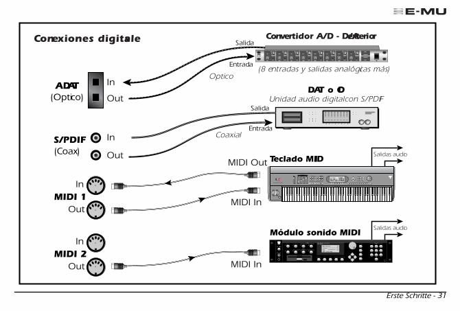
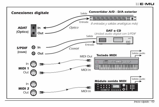
DAT o CD
Convertidor A/D - D/A exterior
8 entradas y salidas analógicas más)
Teclado MIDI
Módulo sonido MIDI
MIDI In
MIDI In
MIDI Out
Salida
Entrada
Salida
Salidas audio
Salidas audio
Entrada
Optico
Coaxial
MIDI 1
S/PDIF(coax)
ADAT(Optico)
MIDI 2
In
Out
In
Out
In
Out
In
Out
Conexiones digitale
Spanish Mana.fm Page 43 Thursday, March 10, 2005 3:09 PM

44 - E-MU Digital Audio System
5 - MicroDock & MicroDock M
El MicroDock se conecta a la tarjeta CardBus E-MU 02 por medio del cable EDI. El panel frontal de este MicroDock le ofrece 2 entradas balanceadas de preamplificador de micro/línea, 8 canales de entrada/salida digital ADAT, entrada/salida digital S/PDIF stereo y una salida de auriculares stereo con control de volumen/interruptor de encendido.
Conexiones del panel frontal
Spanish Mana.fm Page 44 Thursday, March 10, 2005 3:09 PM

Inicio rápido - 45
Sección de preamplificador
Puede usar las entradas mono de micro/línea A y B del panel frontal como entradas balanceadas de micrófono, entradas de pastillas hi-Z
de
guitarra, o entradas balanceadas de nivel de línea. Las clavijas combinadas Neutrik aceptan micros que usen un conector XLR standard o entradas de nivel de línea/hi-Z que usen clavijas TRS de 6,3 mm.
Precaución:
Algunos micros no admiten la alimentación fantasma y pueden dañarse. Compruebe las especificaciones y requisitos de su micro antes de usar la alimentación fantasma.
Entrada y salida digital audio S/PDIF
Cada clavija RCA lleva dos canales de audio digital. Puede usar la E/S S/PDIF para la recepción y/o transmisión de datos digitales desde dispositivos digitales externos como unidades DAT, un convertidor analógico-digital o un procesador de señal equipado con entradas y salidas digitales.Puede configurar la salida S/PDIF en el modo tanto Profesional como No-Pro (siempre con resolución de 24 bits). La entrada/salida S/PDIF admite frecuencias de muestreo de 44.1, 48, 96 y 192 kHz.
Entrada y salida digital óptica ADAT
®
• Los conectores ópticos ADAT transmiten y reciben 8 canales de audio a 24 bits usando el formato ADAT tipo 1 y 2 (a 44.1 kHz o 48 kHz).
• Puede usar la señal de reloj word contenida en el torrente de datos de entrada como una fuente de señal de reloj word.
• Puede conmutar los puertos ópticos ADAT para que lleven también S/PDIF óptico.• La señal ADAT también puede ser transmitida y recibida a 96 o 192 kHz usando el standard S/MUX.
El S/MUX ofrece 4 canales audio a 96 kHz y 2 canales audio a la frecuencia de 192 kHz.
Salida de auriculares y control de volumen
Esta salida da señal a unos auriculares stereo standard y el control de volumen que está al lado le permite ajustar el nivel de escucha. Esta salida está conectada de forma permanente con la salida Monitor del PatchMix DSP.La salida de auriculares usa una versión de alta corriente de los amplificadores de salida de alta calidad usados en los otros canales. Por esta razón ofrece una señal muy limpia que puede usar como otra salida stereo si la necesita.
Spanish Mana.fm Page 45 Thursday, March 10, 2005 3:09 PM

46 - E-MU Digital Audio System
Conexiones del panel trasero
Entradas analógicas de nivel de línea
Dispone de cuatro entradas analógicas de nivel de línea balanceadas de 24 bits (Stereo 1-2). Puede usarlas para dar entrada a cualquier señal de nivel de línea como un teclado, reproductor de CD, pletina, etc. (Las entradas analógicas son asignadas a bandas del mezclador en el programa mezclador PatchMix DSP). Puede ajustar el nivel de entrada al standard no-profesional de -10dBV o al audio Pro de +4 en la pantalla I/O del cuadro de diálogo Session Settings. Puede usar cables tanto TRS balanceados como TS no balanceados. Los cables balanceados ofrecen una mejor inmunidad al ruido y un nivel de señal superior en +6 dB, aunque los cables de instrumento mono standard también dan buenos resultados.
Spanish Mana.fm Page 46 Thursday, March 10, 2005 3:09 PM
Inicio rápido - 47
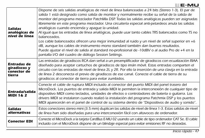
Salidasanalógicas de nivel de línea
Dispone de seis salidas analógicas de nivel de línea balanceadas a 24 bits (Stereo 1-3). El par de salida 1 está designado como salida de monitor y normalmente recibe su señal de la salida de monitor del programa mezclador PatchMix DSP. Todas las salidas analógicas pueden ser asignadas libremente en este programa mezclador. Una circuitería especial anti-petardeos anula las salidas analógicas cuando encienda y apague la unidad. Al igual que las entradas de línea analógicas, puede usar tanto cables TRS balancados como TS no balanceados. Los cable balanceados ofrecen una mejor inmunidad al ruido y un nivel de señal superior en +6 dB, aunque los cables de instrumento mono standard también dan buenos resultados. Puede ajustar el nivel de salida al standard no-profesional de -10dBV o al audio Pro de +4 en la pantalla I/O del cuadro de diálogo Session Settings.
Entradas de giradiscos y conector de tierra
Las entradas de giradiscos RCA dan señal a un preamplificador de giradiscos con ecualización RIAA diseñado para aceptar cartuchos de giradiscos de tipo imán móvil. Estas entradas comparten el circuito con las entradas de nivel de línea 2L y 2R. Por ello la inserción de una clavija en la entrada de línea 2 desconecta el previo de giradiscos de ese canal. Conecte el cable de tierra de su giradiscos al conector de tierra para evitar zumbidos.
Entrada/salida MIDI 1& 2
Conecte el cable de ruptura MIDI incluido al conector del puerto MIDI del panel trasero del MicroDock. Los puertos de entrada y salida MIDI le permiten la interconexión de cualquier tipo de dispositivo MIDI como teclados, unidades de efectos o controladores de batería o guitarra. Los drivers MIDI se instalaron cuando realizó la instalación del programa Patchmix DSP y los puertos MIDI aparecerán en el panel de control de su sistema dentro de “Dispositivos de audio y sonido”.
Salidas alternativas
Estos conectores stereo mini (3.5 mm) duplican las salidas de nivel de línea 1-3. Estas salidas de nivel de línea han sido diseñadas para una interconexión fácil con altavoces de ordenador.
Conector EDI
Conecte el MicroDock a la tarjeta CardBus E-MU 02 usando un cable de tipo ordenador CAT 5e. El cable incluido con el MicroDock dispone de un blindaje especial para evitar emisiones RF no deseadas.
Spanish Mana.fm Page 47 Thursday, March 10, 2005 3:09 PM
48 - E-MU Digital Audio System
Si necesita más información
La sesión
“Product Default”
se carga automáticamente al arrancar la unidad y tiene todas las entradas y salidas asignadas a canales ASIO. No obstante, debe configurar sus programas de grabación audio para que usen
“E-MU ASIO”
.
Consulte los diversos ficheros de ayuda online y el manual de instrucciones (en CD) para una mayor información acerca del E-MU Digital Audio System y los distintos programas. Vea: “Program Files -> Creative Professional -> E-MU 1616 Documents”
Soporte técnico
Dado que nuestro E-MU Digital Audio System va creciendo día a día, querrá disponer siempre de las últimas actualizaciones y el software más moderno para él. Puede encontrar todo esto—y otras informaciones de ayuda—en
www.emu.com
. Consulte el fichero PDF del manual de instrucciones que hay en el CD para localizar el número de teléfono del departamento de soporte técnico.
La información de este documento está sujeta a cambios sin previo aviso y no representa ningún tipo de responsabilidad por parte de E-MU Systems, Inc. Este manual no puede ser reproducido ni transmitido para ningún fin, ni entero ni por partes, por ningún medio, electrónico o mecánico, incluyendo las fotocopias o grabaciones, sin el permiso expreso y por escrito de E-MU Systems, Inc. El software descrito en este documento se envía con un acuerdo de licencia y puede ser usado o copiado solo de acuerdo a lo indicado en dicho acuerdo. La copia de este software en cualquier otro medio salvo lo específicamente permitido en el acuerdo de licencia representa un delito. El usuario solo puede realizar una copia del software con fines de copia de seguridad. E-MU es una marca registrada de E-MU Systems, Inc. en los Estados Unidos de América y/o en otros países.
Copyright © 2005 by E-MU Systems, Inc. Reservados todos los derechos. Versión 1.00 Abril de 2005
Precaución
El manejo de los cables de este aparato puede hacer que quede expuesto al plomo, una sustancia química que, de acuerdo al Estado de California, puede producir cáncer o defectos congénitos. Lávese las manos después de usar esta unidad.
Spanish Mana.fm Page 48 Thursday, March 10, 2005 3:09 PM

Guia Rápido - 49
1 - Introdução
Obrigado por adquirir o Sistema de Áudio Digital E-MU 1616 ou E-MU 1616M. Nós designamos o Sistema de Áudio Digital E-MU para ser lógico, intuitivo e acima de tudo, para fornecer som de alta fidelidade. Ambos os sistemas fornecem gravação e reprodução multicanal de 24-bits/192kHz em uma qualidade de estúdio verdadeiro por um preço fantástico.
Requerimentos do Sistema
• Processador de Intel Genuíno Pentium III, AMD K6 operando em 500 MHz ou superior• Placa Mãe e chipset 100% compatível com Intel ou AMD• Windows 2000 SP4, ou Windows XP SP1• 256 MB RAM• 500 MB de espaço livre no seu disco rígido para instalação completa• Slot disponível tipo 2 (Cardbus)• XVGA Video (1024 x 768)• CD-ROM drive para instalação do software• Fone de ouvidos ou caixas acústicas amplificadas
Outros aplicativos podem ter requerimentos de sistema maiores ou podem requer um microfone.
Componentes Incluídos
E-MU 1616 E-MU 1616M
• Placa E-MU 02 CardBus• MicroDock• Adaptador AC +48VDC • Cabo EDI (E-MU Interface Digital)• Cabo MIDI Breakout• CD de Instalção e de Aplicativos• Manual de Instruções (no CD)• Este Guia Rápido
• Placa E-MU 02 CardBus• MicroDock M
(Conversores classif. Master)
• Adaptador AC +48VDC• Cabo EDI (E-MU Interface Digital)• Cabo MIDI Breakout• CD de Instalação e de Aplicativos• Manual de Instruções (no CD)• Este Guia Rápido
1616 GS.fm Page 49 Thursday, March 10, 2005 3:16 PM
50 - Sistema de Áudio Digital E-MU
2 - Instalação do Hardware
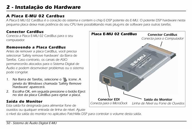
A Placa E-MU 02 Cardbus
A Placa E-MU 02 CardBus é o coração do sistema e contem o chip E-DSP potente do E-MU. O potente DSP hardware nesta pequena placa deixa mais potência do seu CPU livre possibilitando mais plug-ins de software para outras tarefas.
Conector CardBus
Conecta a Placa E-MU 02 CardBus para o seu computador.
Removendo a Placa CardBus
Antes de remover a placa CardBus, você precisa selecionar 'Safety remove hardware' da Barra de Tarefas. Caso contrario, os canais de ASIO permanecerão alocados para o Sistema Digital de Áudio e podem desenvolver problemas ou o sistema pode congelar.
1. Na Barra de Tarefas, selecione o ícone. A janela do Windows chamada 'Safety Remove Hardware' aparecerá.
2. Escolha OK, em seguida pressione o botão Eject no slot da placa CardBus para ejetar a placa.
Saída do Monitor
Esta saída foi designada para alimentar fone de ouvidos ou qualquer entrada de linha de nível. Ajuste o nível da saída do monitor no aplicativo PatchMix DSP para controlar o volume desta saída.
Conector EDIConecta para o MicroDock
Saída do MonitorLinha de Nível ou Fone de Ouvidos
Conector CardBusConecta para o Computador
Placa E-MU 02 CardBus
1616 GS.fm Page 50 Thursday, March 10, 2005 3:16 PM

Guia Rápido - 51
Conectando o MicroDock para a Placa 02 CardBus
Conecte o cabo EDI (incluído no pacote) da tomada RJ-45 na placa E-MU 2 CardBus com a etiqueta 'EDI', para a tomada com a etiqueta 'EDI no MicroDock.O tipo de cabo é de rede padrão CAT 5e que é especificamente protegido para prevenir emissões RF. Entre em contato com E-MU Systems caso você necessite trocar de cabo.
AVISO:
Não conecte o MicroDock ou placa 02 CardBus para conectores de Ethernet ou rede. Fazendo isto pode resultar em danos permanentes ao seu computador, hardware E-MU ou ambos.
Fornecendo potência ao MicroDock
O MicoDock recebe alimentação através do adaptador +48VDC fornecido. Conecte o adaptador para a tomada marcada com +48VDC no painel traseiro do MicroDock. Ligue o MicroDock girando o controle de volume de fone de ouvidos.
EDI
48 VDC+ -
Adaptador+48V DC
Placa 02 CardBusO controle de volume do fone de ouvidos também serve como interruptor de
Importante - Leia antes de instalarSe você esta utilizando o Creative Audigy 2 ZS Notebook Sound Blaster, você deve desinstalar o software do Creative e drivers do seu sistema ANTES de instalar os drivers do E-MU. A partir do momento que os drivers do E-MU forem instalados corretamente, você pode reinstalar os drivers do Audigy 2 ZS caso queira.
1616 GS.fm Page 51 Thursday, March 10, 2005 3:16 PM

52 - Sistema de Áudio Digital E-MU
3- Instalação de Software
Instalando e desinstalando os drivers do Sistema de Áudio Digital e aplicativos
Instale o Software Patchmix DSP e drivers na primeira vez que você reiniciar o seu PC após a instalação da placa E-MU 02 CardBus.
Windows 2000 ou Windows XP
(Este software não está compatível com outras versões de Windows.)
1. Após ter instalado o seu Sistema de Áudio Digital, ligue o seu computador. O Windows irá detectar automaticamente o Sistema de Áudio Digital e procurar pelos drivers dos dispositivos.
2. Quando os drivers de áudio forem solicitados, clique no botão
Cancelar (Cancel)..
3. Insira o CD de instalação do software E-MU em seu drive de CD-ROM. Se o modo AutoPlay do Windows estiver habilitado para o drive do CD-ROM, a leitura do CD começa automaticamente. Caso contrário, no desktop do seu Windows, clique em Iniciar (Start) -> Executar (Run) e digite
d:\setup.exe
(substitua
d:\
pela letra do drive do seu CD-ROM drive). Você pode também abrir o CD e clicar duas vezes em setup.exe
4. Uma nova tela de instalação aparece. Siga as instruções da tela para completar a instalação. 5. Escolha "Continue de qualquer forma" ("Continue Anyway") quando aparecer o aviso na tela "Windows Logo
Testing". 6. Quando finalizado, reinicie o seu computador.
Desinstalando todos os Drivers de Áudio e Aplicativos
Às vezes, você talvez tenha que desinstalar ou reinstalar alguns ou todos os aplicativos da placa de áudio e dispositivos de drivers para corrigir problemas, alterar configurações, ou atualizar drivers ou aplicativos obsoletos. Antes de começar, feche todos os aplicativos da placa de áudio. Os aplicativos que estiverem abertos durante a desinstalação não serão removidos.
1. Clique em
Iniciar
->
Configurações -> Painel de Controle.
2. Clique duas vezes no ícone
Adicionar/Remover Programas.
3. Clique em
Instale/Desinstale
ou no botão
Alterar ou Remover Programas.
4. Selecione o driver/aplicativo da
E-MU 1616
na lista e depois clique no botão
Adicionar/ Remover
ou
Alterar/Remover.
5. Na caixa de diálogo
InstallShield Wizard
, selecione a opção
Remover.
6. Clique no botão
Sim.
7.
Reinicie
o seu computador quando finalizado. 8. Você pode agora
reinstalar
os dispositivos dos drivers da placa
PCI E-MU 02 CardBus
já existentes ou atualizados.
1616 GS.fm Page 52 Thursday, March 10, 2005 3:16 PM
Guia Rápido - 53
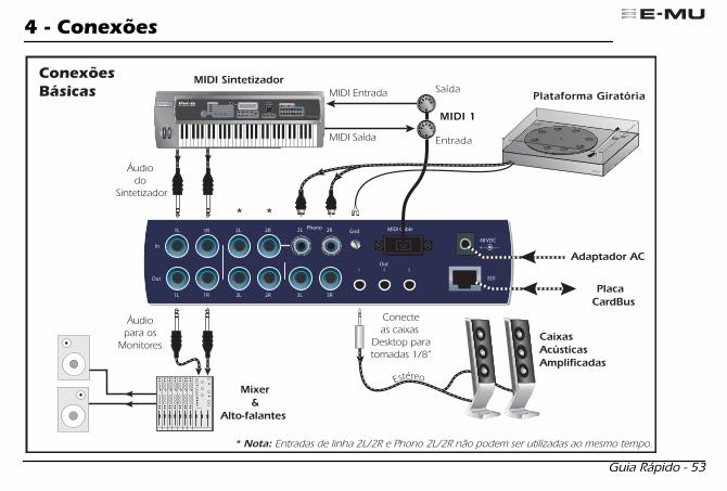
4 - Conexões
1616 GS.fm Page 53 Thursday, March 10, 2005 3:16 PM
54 - Sistema de Áudio Digital E-MU
1616 GS.fm Page 54 Thursday, March 10, 2005 3:16 PM

Guia Rápido - 55
1616 GS.fm Page 55 Thursday, March 10, 2005 3:16 PM
56 - Sistema de Áudio Digital E-MU
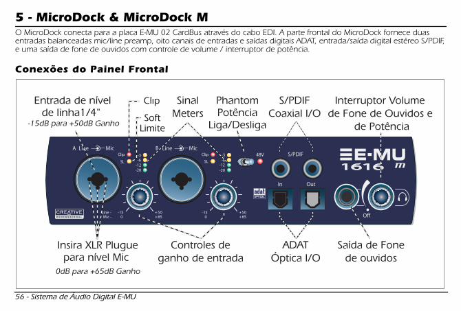
5 - MicroDock & MicroDock M
O MicroDock conecta para a placa E-MU 02 CardBus através do cabo EDI. A parte frontal do MicroDock fornece duas entradas balanceadas mic/line preamp, oito canais de entradas e saídas digitais ADAT, entrada/saída digital estéreo S/PDIF, e uma saída de fone de ouvidos com controle de volume / interruptor de potência.
Conexões do Painel Frontal
1616 GS.fm Page 56 Thursday, March 10, 2005 3:16 PM
Guia Rápido - 57
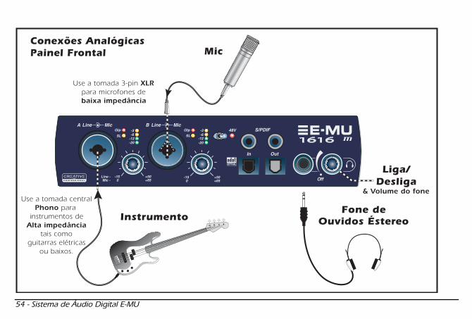
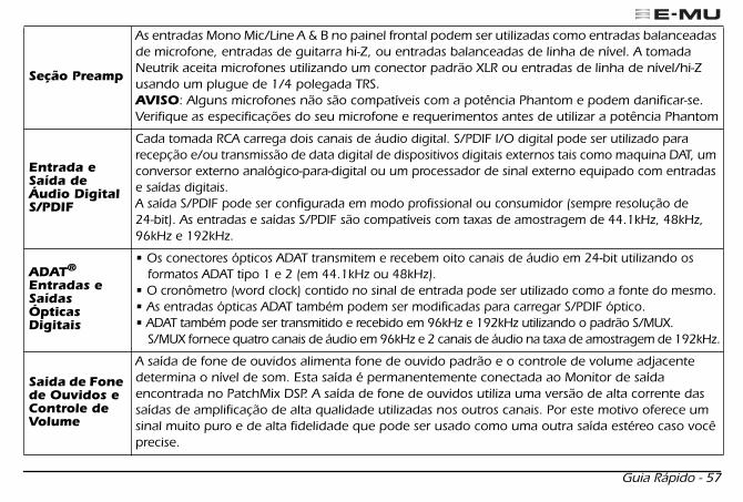
Seção Preamp
As entradas Mono Mic/Line A & B no painel frontal podem ser utilizadas como entradas balanceadas de microfone, entradas de guitarra hi-Z, ou entradas balanceadas de linha de nível. A tomada Neutrik aceita microfones utilizando um conector padrão XLR ou entradas de linha de nível/hi-Z usando um plugue de 1/4 polegada TRS.
AVISO
: Alguns microfones não são compatíveis com a potência Phantom e podem danificar-se. Verifique as especificações do seu microfone e requerimentos antes de utilizar a potência Phantom
Entrada e Saída de Áudio Digital S/PDIF
Cada tomada RCA carrega dois canais de áudio digital. S/PDIF I/O digital pode ser utilizado para recepção e/ou transmissão de data digital de dispositivos digitais externos tais como maquina DAT, um conversor externo analógico-para-digital ou um processador de sinal externo equipado com entradas e saídas digitais.A saída S/PDIF pode ser configurada em modo profissional ou consumidor (sempre resolução de 24-bit). As entradas e saídas S/PDIF são compatíveis com taxas de amostragem de 44.1kHz, 48kHz, 96kHz e 192kHz.
ADAT
®
Entradas e Saídas Ópticas Digitais
• Os conectores ópticos ADAT transmitem e recebem oito canais de áudio em 24-bit utilizando os formatos ADAT tipo 1 e 2 (em 44.1kHz ou 48kHz).
• O cronômetro (word clock) contido no sinal de entrada pode ser utilizado como a fonte do mesmo. • As entradas ópticas ADAT também podem ser modificadas para carregar S/PDIF óptico.• ADAT também pode ser transmitido e recebido em 96kHz e 192kHz utilizando o padrão S/MUX.
S/MUX fornece quatro canais de áudio em 96kHz e 2 canais de áudio na taxa de amostragem de 192kHz.
Saída de Fone de Ouvidos e Controle de Volume
A saída de fone de ouvidos alimenta fone de ouvido padrão e o controle de volume adjacente determina o nível de som. Esta saída é permanentemente conectada ao Monitor de saída encontrada no PatchMix DSP. A saída de fone de ouvidos utiliza uma versão de alta corrente das saídas de amplificação de alta qualidade utilizadas nos outros canais. Por este motivo oferece um sinal muito puro e de alta fidelidade que pode ser usado como uma outra saída estéreo caso você precise.
1616 GS.fm Page 57 Thursday, March 10, 2005 3:16 PM
58 - Sistema de Áudio Digital E-MU
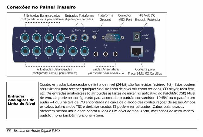
Conexôes no Painel Traseiro
Entradas Analógicas de Linha de Nível
Quatro entradas balanceadas de linha de nível (24-bit) são fornecidas (estéreo 1-2). Estas podem ser utilizadas para receber qualquer sinal de linha de nível tais como teclados, CD-player, toca-fitas, etc. (As entradas analógicas são atribuídas às faixas de mixer no aplicativo do PatchMix DSP.) Nível de entrada pode ser configurado para acomodar o padrão consumidor -10dBV, ou o padrão pro áudio +4 dBu na tela de I/O encontrada na caixa de dialogo das configurações de sessão.Ambos os cabos balanceados TRS e desbalanceados TS podem ser utilizados. Cabos balanceados oferecem melhor imunidade contra ruídos e um nível de sinal +6dB, mas cabos de instrumento padrão mono também funcionam bem.
1616 GS.fm Page 58 Thursday, March 10, 2005 3:16 PM
Guia Rápido - 59
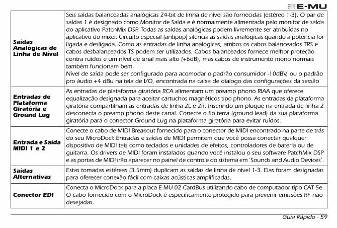
Saídas Analógicas de Linha de Nível
Seis saídas balanceadas analógicas 24-bit de linha de nível são fornecidas (estéreo 1-3). O par de saídas 1 é designado como Monitor de Saída e é normalmente alimentada pelo monitor de saída do aplicativo PatchMix DSP. Todas as saídas analógicas podem livremente ser atribuídas no aplicativo do mixer. Circuito especial (antipop) silencia as saídas analógicas quando a potência for ligada e desligada. Como as entradas de linha analógicas, ambos os cabos balanceados TRS e cabos desbalanceados TS podem ser utilizados. Cabos balanceados fornece melhor proteção contra ruídos e um nível de sinal mais alto (+6dB), mas cabos de instrumento mono normais também funcionam bem.Nível de saída pode ser configurado para acomodar o padrão consumidor -10dBV, ou o padrão pro áudio +4 dBu na tela de I/O, encontrada na caixa de dialogo das configurações da sessão
Entradas de Plataforma Giratória e Ground Lug
As entradas de plataforma giratória RCA alimentam um preamp phono RIAA que oferece equalização designada para aceitar cartuchos magnéticos tipo phono. As entradas da plataforma giratória compartilham as entradas de linha 2L e 2R. Inserindo um plugue na entrada de linha 2 desconecta o preamp phono deste canal. Conecte o fio terra (ground lead) da sua plataforma giratória para o conector Ground Lug na plataforma giratória para evitar ruídos.
Entrada e Saída MIDI 1 e 2
Conecte o cabo de MIDI Breakout fornecido para o conector de MIDI encontrado na parte de trás do seu MicroDock.Entradas e saídas de MIDI permitem que você possa conectar qualquer dispositivo de MIDI tais como teclados e unidades de efeitos, controladores de bateria ou de guitarra. Os drivers de MIDI foram instalados quando você instalou o seu software PatchMix DSP e as portas de MIDI irão aparecer no painel de controle do sistema em ́ Sounds and Audio Devices´.
Saídas Alternativas
Estas tomadas estéreas (3.5mm) duplicam as saídas de linha de nível 1-3. Elas foram designadas para oferecer conexão fácil com caixas acústicas amplificadas.
Conector EDI
Conecta o MicroDock para a placa E-MU 02 CardBus utilizando cabo de computador tipo CAT 5e. O cabo fornecido com o MicroDock é especificamente protegido para prevenir emissões RF não desejadas.
1616 GS.fm Page 59 Thursday, March 10, 2005 3:16 PM
60 - Sistema de Áudio Digital E-MU
Obtendo Maiores Informações
A sessão ́
Product Default
´ é automaticamente carregada durante reinicio e possui todas as entradas e saídas configuradas para os canais ASIO. Entretanto, você deve configurar os seus aplicativos de gravação de áudio para utilizar
"E-MU ASIO".
Por favor, consulte os vários arquivos de ajuda na Internet e o manual de instruções (no CD) para informação mais detalhada do Sistema de Áudio Digital E-MU e vários aplicativos. Veja: “Program Files -> Creative Professional -> E-MU 1616 Documents”
Suporte Técnico
Conforme a expansão do Sistema de Áudio Digital do E-MU, você pode se manter atualizado com os softwares mais recentes e novas opções para o seu Sistema de Áudio Digital E-MU. Você pode encontrar tudo isso - e outras informações interessantes- no site
www.emu.com.
Consulte o manual de instruções em formato PDF no CD fornecido para obter o numero de telefone do suporte técnico.
Informação neste documento é sujeito a alterações sem aviso prévio e não representa compromisso por parte da E-MU. Este manual não pode ser reproduzido de forma alguma, seja eletrônica, mecânico, incluindo fotocópia e gravação sem a permissão escrita do E-MU Systems Inc.O software descrito neste documento foi elaborado sob acordo de licencia e pode ser utilizado ou copiado somente de acordo com os termos da mesma. Reprodução de software é contra a lei em quaisquer mídia excetos aquelas especificadas no acordo de licencia. Esta licencia permite ao usuário fazer uma copia do software somente para fins de backup.E-MU é marca registrada do E-MU Systems, Inc nos Estados Unidos e/ou qualquer outro pais.
Copyright © 2005 E-MU Systems, Inc. Todos os diretos reservados.Versão 1.00 Abril 2005
1616 GS.fm Page 60 Thursday, March 10, 2005 3:16 PM

���������� - 61
1 - �� �� �� �� ��� Creative Professional E-MU ������������� E-MU 1616 m� E-MU 1616������ !"#$% &'()*�+�",-�� E-MU�������������./012340567(895:* �;�<=>$?'�@��ABC<DE�F��G���HI#�C<JK���� 24bit/192kHz)�*����LM<��N��O�P�QQR<S�TC���<U /VT�F��(895�����VGW��<UX������Y<Z)[\=]",-
^̂̂̂7777____ `̀̀̀ • Intel
®
Pentium
®
III 500 MHzab�VGW�L
• IntelcdQ�VW��ef • Microsoft® Windows® 2000 Professional SP4ab�"� Windows XP SP1abg 1 • 256MB ab�����hiN • 500 MB�j!kl�mn�o�����p�qrs��<����tu • vw895E�F�r��V 2u�G�� • XGAr 1024 x 768uab�xy(895���VT�z{V��)i|�� • Bs�M}z��<����w CD-ROMp�q"� DVD-ROMp�q • �<��S�� ~�895_`r�F��p�FDzVN���Y<��z�V��� ��ug 2 • ��s�<�"�z���q�J�E�����r��'u��zVN���Y< :n$�:'������DP��Gs�<5������(�� 5�1�#>"]�-g 1 Windows 2000 Server / Advanced Server�?:� 64bit � Windows XP ��#$?'"]�g 2 �<��S�� ~�,�����w?����)5'",
AAAA������������������������
g 1 L�A����Bs�M}z�L����n$?'"]�-�� ¡=�-
E-MU 1616 E-MU 1616
m
• E-MU 02 CardBus PCMCIA E� • MicroDock• +48VDC ACz{V�� • EDIr E-MU Digital Interfaceu��q� • MIDIqT��zM���q� • E-MU Digital Audio System Software/Driver Install CD• Production Tools Software Bundle CDrL�A����Bs�M}zug 1
• ��¢�£P|Kz�r�<���� CD ¤¥u • ����������r¦§u
• E-MU 02 CardBus PCMCIAE� • MIcroDock MrP��N<UUT�C<F��u • +48VDC ACz{V�� • EDIr E-MU Digital Interfaceu��q� • MIDIqT��zM���q� • E-MU Digital Audio System Software/Driver Install CD• Production Tools Software Bundle CDrL�A����Bs�M}zug 1
• ��¢�£P|Kz�r�<���� CD ¤¥u • ����������r¦§u
�❂�❂ ✴✺�❇� ✩✤�� ����������������������

62 - E-MU�������������
2 - o�M}z�o�M}z�o�M}z�o�M}z�¨̈̈̈''''©©©©ªªªª E-MU 02 CardBus PCMCIA E�E�E�E�
E-MU 02 CardBus PCMCIAE�ra¡ E-MU 02 PCE�u� E-MU��������������«¬)�®",-�¯9 E-DSPVGW�L�°±#�C<JK����²�� CPU �#$³´µ��¶O�·t 16 ¸ab���¹º5o�M}z»���������N���¼s}���Nz���� vw,��)(O!",-
E-MU 02 PCEEEE��������HHHH½½½½,,,,���� E-MU 02 PCE��?v��C<JK���� PCMCIA�G�� ¾�#",- PCE�d#�¿!O5ª>À�d#ÁÂ#ÃÄ�)(O!"]��O��ÅÆ¡=�-
E-MU 02 PCEEEE��������¨̈̈̈''''ÇÇÇÇ#### E-MU 02 PCE��¨'Ç,È ��É Windows���F�1Ê "o�M}z�¨'Ç# "�ËÌ#�¨'Ç#�ÍÎ�ÏÐ#$1Ê�E��C<JK���1ʨ'Ç#$¡=�-��7Ñ��ÒÉ o�M}z�¨'Ç#�ÓÔ� E-MU�������������) ASIO ��zVN���Y<ÕO ASIO QR<S�(Ö'×$Ê>�"")5'�zVN���Y<bOØÙ(ÚÛ#�'�sN�£,�89¯(&'",-
1. Windows ���F�b� z�C<bOPM���
N��#�xy=>� "o�M}z�¨'Ç# ")�*Ü���Vz�V�ËÌ#",-
2. o�M}z�ÍÎ(ÏÐ=>��)�ÝÊ]�{�zGUÞ���(xy=>",�O� OKÞ�<��N��#$1Ê� E-MU 02 PCE��C<JK���1Êß!¨'",-
iiii||||��������ààààáááá��àáâã���T���s�<"�p�<�áâã�m2�ä�~�,��)(O!",-��àá�ÞNK���©å,� PatchMix DSPæçL�zVN���Y<b�i|��àáÞNK��Oèé#",-
EDICS��CS��CS��CS��r MicroDock�~�u
i|��i|��i|��i|��àáàáàáàárp�<T»� /��s�<u
CardBusCS��CS��CS��CS��rC<JK���Z¾�u
E-MU 02 PCEEEE����
�❂�❂ ✴✺�❇� ✩✥�� ����������������������
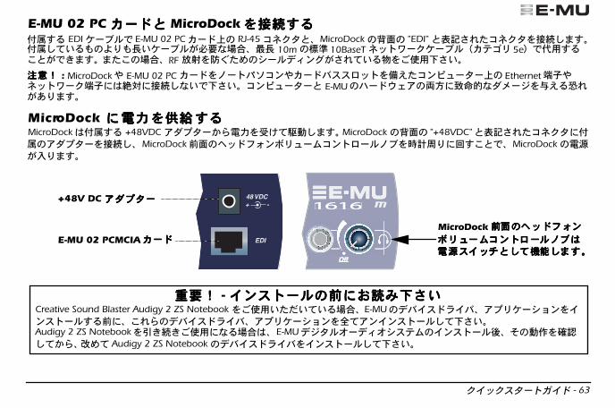
���������� - 63
E-MU 02 PC E�)E�)E�)E�) MicroDock����~�~�~�~�,�,�,�,�©å,� EDI��q�O E-MU 02 PCE�b� RJ-45CS��)� MicroDock�êë� "EDI")xì=>�CS���~�#",-©å#$����:'�í���q�(��5ÓÔ�³í 10m�îï 10BaseT S��X����q�rE�ðN 5euOñw,��)(O!",- "���ÓÔ� RF òó�ôõ��������<U(=>$��ö��vw¡=�-
ÅÅÅÅÆ÷Æ÷Æ÷Æ÷ : MicroDockD E-MU 02 PCE��@��ABC<DE�F��G���I®�C<JK���b� EthernetâãDS��X��âã ø� ~�#5�O¡=�-C<JK���) E-MU�o�M}z�ùú ûü05{h���ý®�þ>(&'",-
MicroDock ����áááá������������,,,,���� MicroDock©å,� +48VDC z{V��1Ê�á��ª$�^#",- MicroDock �êë� "+48VDC")xì=>�CS�� ©å�z{V���~�#� MicroDockÈë���s�<ÞNK��C<�G��@q�t��' �,�)O� MicroDock��(�'",-
EDI
48 VDC+ -
+48V DC z{V��z{V��z{V��z{V��
E-MU 02 PCMCIAE�E�E�E� MicroDockÈÈÈÈëëëë������������ssss����<<<<ÞÞÞÞNNNNKKKK��������CCCC<<<<����GGGG��������@@@@qqqq����������������QQQQ))))####$$$$����9999####"""",,,,----
����÷÷÷÷ - �<������<������<������<�����ÈÈÈÈ ? ? ? ?�����¡=��¡=��¡=��¡=� Creative Sound Blaster Audigy 2 ZS Notebook ��vw�� �$��ÓÔ� E-MU��F��p�F�zVN���Y<��<����,�È ��>Ê��F��p�F�zVN���Y<�Î$z<�<����#$¡=�- Audigy 2 ZS Notebook� !�!�vw 5�ÓÔ� E-MU���������������<��������^7�ÏÐ#$1Ê� ��$ Audigy 2 ZS Notebook��F��p�F��<����#$¡=�-
�❂�❂ ✴✺�❇� ✩✦�� ����������������������

64 - E-MU�������������
3 - �F��p�F��F��p�F��F��p�F��F��p�F�zVN���Y<��<����zVN���Y<��<����zVN���Y<��<����zVN���Y<��<���� E-MU������������������������FFFF��������pppp����FFFF))))zzzzVVVVNNNN������������YYYY<<<<��������<<<<���������������� /zzzz<<<<����<<<<���������������� E-MU 02 PCE���<�������F��p�F) PatchMix DSPæçL�zVN���Y<��<����#",-
Windows 2000 Professional?:�?:�?:�?:� Windows XP r������T���<U����L���=>$�"]�u 1. E-MU 02 PCMCIAE��¾�(��#�Ê�VpUz<VT� :n$ Windows ( E-MU 02 PCE���^Ð�#��F��p�F��<����,�:*��$!",-
2. �F��p�F��<������,{�zGUÞ���(xy=>�Ê�����çR<W��çR<W��çR<W��çR<W�� Þ�<��N��#$¡=�- 3. "
E-MU Digital Audio System Software/Driver CD
"�p»��2�� CD-ROM� CD-ROM/DVD-ROMp�q ¾�#",-
�<���p�(�^0 �^#��F��p�F) PatchMix DSPzVN���Y<��<����(��=>",-�<���p�(�^0 �^#5�ÓÔ� Windows�����h|K�1Ê����ssss����������������������������####$$$$ ���������ËÌ#�! d:\ctrun\start.exe"r dp�q( CD-ROMp�q�ÓÔu)�á#����� OK����Þ�<��N��#$¡=�-"���<���� CD��!����� ctrun����s��{ &����� start.exe�����{q��N��,��)O���<���p�(�^#",-
4. �<���p���Vp��K#ë(xy=>�Ê��<���p���y $n$� "ɳ% ?&"��'(r)¦�ÓÔ����z�z�z�z�z�z�z�z�u�ËÌ#��ª$?v��*+r����)¦)¦)¦)¦+�+�+�+�u�ËÌ#",-, �F��p�F)zVN���Y<��<����#���V�Y<�ËÌ#$�����<������<������<������<�����Þ�<��N��#�W��z�V���=]$¡=�-
5. �<�����-.O! WindowsGð��� Gð��� Gð��� Gð��� ÔÔÔÔ/#$�"]�/#$�"]�/#$�"]�/#$�"]�")�*01#ë(à�ÓÔ(&'",(�����������������Þ�<��N��#$¡=�r23�<���� CD ¤¥=>$����¢�£P|Kz� ì±=>$�",u-
6. 4�^��=>",�O��y $n$C<JK����4�^#$¡=�-
�F��p�F�zVN���Y<���F��p�F�zVN���Y<���F��p�F�zVN���Y<���F��p�F�zVN���Y<��ÎÎÎÎ555556565656 71ØÙ(Û��)!�8��%98� :#��)!D�³;��F��p�FDzVN���Y< <;,�)!Î$��F��p�F�zVN���Y<�=�Î$56#��<����#3,�)(�� 5��)(&'",-��> �É PatchMix DSPæçL�)?@,������zVN���Y<�A�#$1Ê�n$¡=�-567Ñt �^#$��zVN���Y<56,��)(O!"]��O�ÅÆ¡=�- 1.������������������������B����8�8�8�8�����B����C<�G��AS��C<�G��AS��C<�G��AS��C<�G��AS��r"�������������������������B����C<�G��AS��C<�G��AS��C<�G��AS��C<�G��AS��u�C �N��#�C<�G��AS���!",-
2.����zVN���Y<�zVN���Y<�zVN���Y<�zVN���Y<�DDDDE)E)E)E)56565656����z�C<r"�����VGUp��VGUp��VGUp��VGUp��DDDDE)E)E)E)56565656����z�C<u�{q��N��#",- 3.����VGUp��VGUp��VGUp��VGUp��DDDDE)E)E)E)56565656�����q��N��#",- 4. ¼<�N�1Ê���� E-MU 1616�����ËÌ#$����FFFF<<<< / 56565656����Þ�<��N��#",- 5.���� InstallShield Wizard����{�zGUÞ���(xy=>",�O�����56565656�����ËÌ#�����,,,,Z�Z�Z�Z�Þ�<��N��#",- 6. 4�^,�Ü�G�$!",�O��y $n$C<JK����4�^#$¡=�- 7. H���"�³;��F��p�F�?:� PatchMix DSP zVN���Y<�4�<����#$¡=�-
�❂�❂ ✴✺�❇� ✩✧�� ����������������������
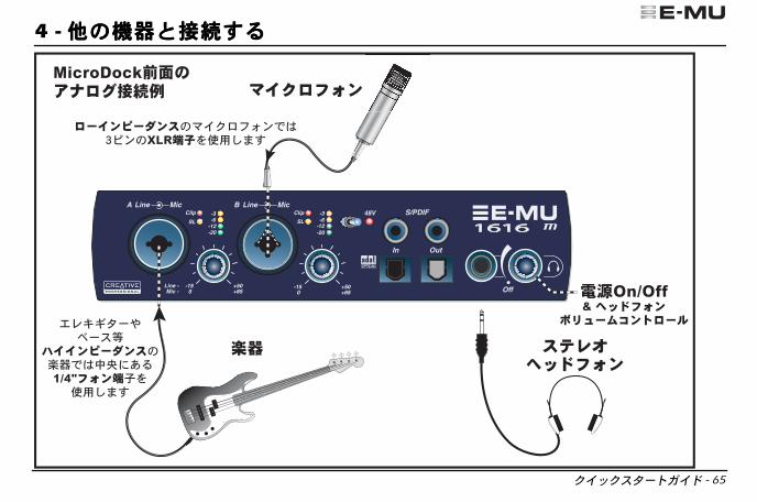
���������� - 65
4 - ������ä)��ä)��ä)��ä)~�~�~�~�,�,�,�,�
�❂�❂ ✴✺�❇� ✩!�� ����������������������

66 - E-MU�������������
�❂�❂ ✴✺�❇� ✩✩�� ����������������������
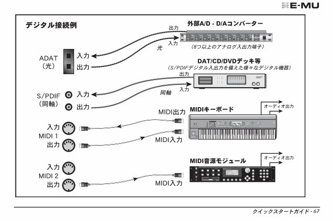
���������� - 67
�❂�❂ ✴✺�❇� ✩✪�� ����������������������
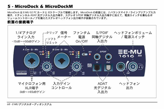
68 - E-MU�������������
5 - MicroDock & MicroDockM
MicroDock E-MU 02 PCE�) EDI��q�O~�#",- MicroDock�Èë � 2Fp<�P�� /p�<VNz<V�áâã� 8QR<S� ADATI�����àáâã���T� S/PDIF·J�����àáâã E®$�����Q�KL�ÞNK��C<�G��@q�I®���T���s�<àáâã(HI=>$�",-
ÈëÈëÈëÈë����~�âã~�âã~�âã~�âã
-15 0
+50+65
-15 0
+50+65
�❂�❂ ✴✺�❇� ✩✫�� ����������������������
���������� - 69
VNz<VVNz<VVNz<VVNz<VW��Y<W��Y<W��Y<W��Y<
MicroDockÈë�i@p�P�� /p�<�á A) B�Fp<�P��Gs�<�á� Hi-ZM���á�Fp<�p�<T»��á)#$vw,��)(O!",-ù�áâãN Neutrik�C<OS��Y<�R���Pw#$?'� XLRâã� 1/4" TRSs�<âã�~�,��)(O!",-"���>Q>�âã RS#�T�<C<�G��@q(HI=>$?'�P���á /p�<�á��>Q>O³U5VWT»��èé,��)(O!",-ÅÅÅÅÆÆÆÆ : P��Gs�< :n$s�<����vwO!É�XY,�þ>(&'",-s�<����vw,�È �P���¨Z[\§�:ÁÏÐ#$Á =�-
S/PDIF·J·J·J·J�����������������àá�àá�àá�àá
22�îï RCA J<�R���>Q> 2QR<S���������������]�V#",- S/PDIF�����àá DATDÇ A/DC<F��5�)�����������]�V���������àáâã�m2Ǽs}���5� ~�,��)(89O,- "� S/PDIF�����àáVGs}��Y¢� /C<�K�P�i��^'_®�`(O!",- S/PDIF�����á /àá)� 24bit �TaNK��Y<O 44.1kHz� 48kHz� 88.2kHz� 96kHz� 176.4kHz� 192kHz�L<VN<U�bc�Z*�)(O!",-
ADAT
®
I����I����I����I�����àá�àá�àá�àá
ADATI�����àáO ADAT��V 1"���V 2s��P��� 8 QR<S�d� 24bit�����]�V,�`(O!",r 44.1kHz/48kHztu-�á��� e">� Word Clock VW Word ClockB��)#$vw,��)(89O,-=Ê PatchMix DSPBs�M}zbO S/PDIFI�����àáâãZ)^'_®��)(89O,- 88.2� 96� 176.4� 192kHz�L<VN<U�bcO� ADAT�]�V� S/MUX��<{��vw#��� ADATQR<S��fw#$��)=>�g(h� H#",- 88.2/96kHzt � 4�����QR<S�� 176/192kHzt 2�����QR<S�)5'",-
��s�<��s�<��s�<��s�<àáàáàáàá & ÞNK��C<�G��ÞNK��C<�G��ÞNK��C<�G��ÞNK��C<�G��
��s�<àá =i05��T���s��~�#�ÞNK��C<�G��O��jl�èé#",-"�����s�<àá PatchMix DSPæçL�zVN���Y<b�i|��àá�VW(àá=>",-����s�<àá�� ��$����T�zM�)#$�vwO!�� �kl �N�<5VW�àá#",-������s�<z<V��QR<S�Ovw=>$��ö:'��àá12o���N���5z<V�vw#$�",-
�❂�❂ ✴✺�❇� ✩✬�� ����������������������

70 - E-MU�������������
êëêëêëêë����~�âã~�âã~�âã~�âã
p�<T»�p�<T»�p�<T»�p�<T»�z¢GUz¢GUz¢GUz¢GU�á�á�á�á
42r 1m 2��T��zu�Fp<� 24bit p�<T»�z¢GU�á �ç�Þ�� CDVT�n��EW����ç5��p�<T»�VW��á,��)(O!",-�>Ê�z¢GU�á PatchMix DSPæçL�zVN���Y<OæçL��á��N�V zL�<#$vw#",-"�C<�K�P�äOîï05 -10dBV"�VG������äOîï0 vw=>� +4dBu)�^'_®��)(O!",-�>Ê��á TRSFp<���q�) TSz<Fp<���q���oÊO�vw89O,-Fp<���q�@�£ pÁ� +6dB��VWT»� 5'",-#1#=i05i@p��qäw��q�O�r�ØÙ&'"]�-
�❂�❂ ✴✺�❇� ✪✣�� ����������������������
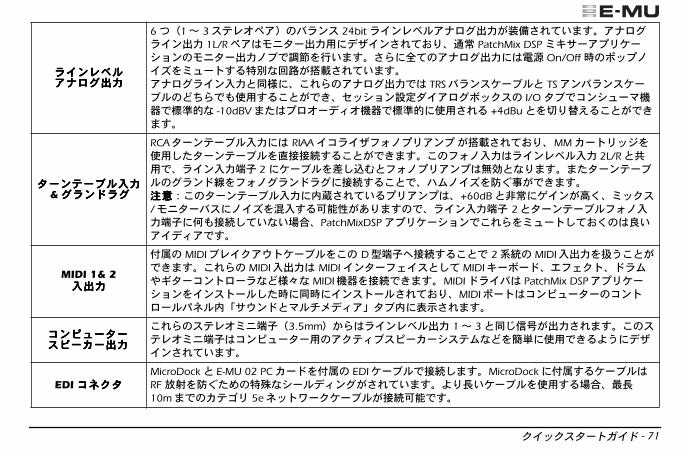
���������� - 71
p�<T»�p�<T»�p�<T»�p�<T»�z¢GUz¢GUz¢GUz¢GUàáàáàáàá
62r 1m 3��T��zu�Fp<� 24bit p�<T»�z¢GUàá(HI=>$�",-z¢GUp�<àá 1L/R�zi|��àáw �;�<=>$?'�sl PatchMix DSP æçL�zVN���Y<�i|��àá@qOèé���",-=Ê Î$�z¢GUàá � On/Offt���V@�£�æK��,�t�5�u(°±=>$�",-z¢GUp�<�á)·� ��>Ê�z¢GUàáO TRSFp<���q�) TSz<Fp<���q���oÊO�vw,��)(O!�W��Y<8�{�zGUÞ���� I/O�qOC<�K�P�äOîï05 -10dBV"�VG������äOîï0 vw=>� +4dBu)�^'_®��)(O!",-
��<��q���<��q���<��q���<��q��á�á�á�á & Up<pUUp<pUUp<pUUp<pU
RCA��<��q��á RIAA �Cp�;s�@VNz<V (°±=>$?'� MME��N���vw#���<��q��3~~�,��)(O!",-��s�@�áp�<T»��á 2L/R)NwO�p�<�áâã 2 ��q��Â#ÃÄ)s�@VNz<Vvw)5'",-"���<��q��Up<x�s�@Up<pU ~�,��)O�o�@�£�ôõ`(O!",-ÅÅÅÅÆÆÆÆy����<��q��á z{=>$��VNz<V� +60dB)kl T�<(�Á�æ��� /i|��F� @�£�|�,�89¯(&'",�O�p�<�áâã 2)��<��q�s�@�áâã 7�~�#$�5�ÓÔ� PatchMixDSPzVN���Y<O�>Ê�æK��#$?Á�}�z���zO,-
MIDI 1& 2 �àá�àá�àá�àá
©å� MIDIqT��zM���q���� D~âãZ~�,��)O 2��� MIDI�àá�Z*�)(O!",-�>Ê� MIDI�àá MIDI�<��s}��)#$ MIDIç�Þ��¼s}���p�DM��C<�G�p5���5 MIDI�ä�~�O!",- MIDIp�F PatchMix DSPzVN���Y<��<����#�t ·t �<����=>$?'� MIDI���C<JK����C<�G��AS�z!LM<)P�Qh��z"�qz xy=>",-
C<JK���C<JK���C<JK���C<JK����J�E��J�E��J�E��J�E�àáàáàáàá
�>Ê���T�æ|âãr 3.5mmu1Êp�<T»�àá 1m 3)·�VW(àá=>",-����T�æ|âãC<JK���w�z���q�J�E�����5���� vwO!�:* �;�<=>$�",-
EDI CS��CS��CS��CS�� MicroDock) E-MU 02 PCE��©å� EDI��q�O~�#",- MicroDock ©å,���q� RFòó�ôõ���t�5�����<U(=>$�",-:'í���q��vw,�ÓÔ�³í 10m"O�E�ðN 5eS��X����q�(~�89O,-
�❂�❂ ✴✺�❇� ✪✤�� ����������������������
72 - E-MU�������������
�������������?�?�?�?@��@��@��@�� E-MU���������������<����#�³% �^#���O� " Product Default "W��Y<( PatchMix DSPzVN���Y< G�=>$�",-��W��Y<O���Î$��áâã)àáâã(�>Q> ASIO QR<S� Ö'×$Ê>$�",-�>Ê�8���w vw,� �?v�� ASIO ��zVN���Y<O� "E-MU ASIO"p�F�ËÌ#$¡=�- PatchMix DSPæçL��2#��� 2�$��<���� CD ¤¥=>$����¢�£P|Kz����#$¡=�-"������¢�£P|Kz� E-MU���������������F��p�F�zVN���Y<��<����#�t �·t o�����Z�CJ�=>",r%98�O�a¡�G���Y< 5'",u- Cp�q -> Program Files -> Creative Professional -> E-MU 1616 Documents
��|E�L�����|E�L�����|E�L�����|E�L������������F��p�F�zVN���Y<���¢�£P|Kz�DQK��Nz�P|Kz���¹����¹ FAQ �<;����M}qL�� http://jp.creative.com/ $�t<;=>���O,-��E��P�L���Z�?Ø�ÔÒ]���M}qL������¡=�-
¦§�zk��}����1vÁF<=>�ÓÔ(&'",-¦§ì±zk �ID�U^5xH(&'�?���������ÓÔO�� E-MU Systems, Inc.?:��N¼���qh��z����O=^����û#1L",- E-MU Systems, Inc."���?�����15�ÓÔ ?�$�3~0�Õ~0�©�0���0��É>1 :'Û��O�S�b�f������������� 0Y¡¢£"�t�5Y¡¢£ 2�$� E-MU Systems, Inc."���?���(�*#�Y¡�ÚÛ89¯�sÝ=>$��ÓÔO&n$��=^�¤¥���"]�-�¦0"���§0��D��¨�Dú©�ØÒÉ���:*5ª0O&>���[\§��15�d� E-MU Systems, Inc.)�§ë :�«8�¬��)5Á��#�'®]#�',��)à¯"]�-�> °±°D¥j�e">",-¦§O[\=>�Bs�M}z�p�W<�²³��)�ý=>���O&'�p�W<�²³�´µ ¶#$�>�vw#�'CJ�#�',��)à¯"]�-p�W<�²³Ot «8=>$��ÓÔ�6!�Bs�M}z���h��z CJ�,��)�©·¸¶)5'",-p�W<��¹º�F��z�V)#$Bs�M}z�CJ�� 17�,��)(à¯�ÓÔ(&'",- E-MU E-MU Systems, Inc.�»¼�?:�����¼� ?ª�½¥¾îO,-
Copyright © 2005 E-MU Systems, Inc. All rights reserved. ¿ 1.0� 2005À 4Á
�❂�❂ ✴✺�❇� ✪✥�� ����������������������


![[mangá] Legend of mana volume 1 [imagine scan]](https://img.pdfslide.us/doc/110x75/568ca6291a28ab186d900aa1/manga-legend-of-mana-volume-1-imagine-scan.jpg)