Embed Size (px)
Citation preview
1
Encrypt Flip-Flop: A Novel Logic EncryptionTechnique For Sequential Circuits
Rajit Karmakar, Student Member, IEEE, Santanu Chattopadhyay, Senior Member, IEEE,and Rohit Kapur, Fellow, IEEE
Abstract—Logic Encryption is one of the most popular hard-ware security techniques which can prevent IP piracy andillegal IC overproduction. It introduces obfuscation by insertingsome extra hardware into a design to hide its functionalityfrom unauthorized users. Correct functionality of an encrypteddesign depends upon the application of correct keys, sharedonly with the authorized users. In the recent past, extensiveefforts have been devoted in extracting the secret key of anencrypted design. At the same time, several countermeasureshave also been proposed by the research community to thwartdifferent state-of-the-art attacks on logic encryption. However,most of the proposed countermeasures fail to prevent the powerfulSAT attack. Although a few researchers have proposed differentsolutions to withstand SAT attack, those solutions suffer fromseveral drawbacks such as high design overheads, low outputcorruptibility, and vulnerability against removal attack. Almostall the known logic encryption strategies are vulnerable to scanbased attack. In this paper, we propose a novel encryptiontechnique called Encrypt Flip-Flop, which encrypts the outputs ofselected flip-flops by inserting multiplexers (MUX). The proposedstrategy can thwart all the known attacks including SAT and scanbased attacks. The scheme has low design overhead and imple-mentation complexity. Experimental results on several ISCAS’89and ITC’99 benchmarks show that our proposed method canproduce reasonable output corruption for wrong keys.
Keywords—Hardware Security, Logic Encryption, key-gates, at-tacks and countermeasures, overheads, output corruption.
I. INTRODUCTION
Ever increasing market demand for smarter, faster andsmaller products motivates the electronics design industry todevelop complex chips with a wide range of functionalitieslike digital, analog, radio frequency, photonic, integrated intoa single chip. Manufacturing these complex chips requiresadvanced mixed technology fabrication facilities. The enor-mous cost of setting up and maintaining such fabrication lab(cost of owning a foundry is about $5 billion [1]) is themain impediment for small design houses to own an in-housefoundry. However, globalization in the semiconductor industryhas facilitated integrated circuit (IC) designers to outsource thefabrication of their designs to offshore foundries. Although thistrend significantly cuts down the cost, at the same time, it hasalso opened the backdoor for several security vulnerabilities
Rajit Karmakar and Santanu Chattopadhyay are with theDepartment of Electronics and Electrical Communication Engineering,Indian Institute of Technology, Kharagpur, India, 721032 e-mail:{rajit,santanu}@ece.iitkgp.ernet.in
Rohit Kapur is with Synopsys, USA, e-mail: [email protected] work is partially supported by the research project entitled “Synopsys
CAD Laboratory Projects (CADL)“, sponsored by Synopsys Inc., USA.
KE
Y
INP
UT
S
CORRECT
KEYS
PR
IMA
RY
INP
UT
S
KE
Y
INP
UT
S
OU
TP
UT
S
INCORRECT
KEYS
LOGIC
ENCRYPTED
CIRCUIT
PR
IMA
RY
INP
UT
S
OU
TP
UT
S
LOGIC
ENCRYPTED
CIRCUIT
(a) (b)
Figure 1: Block diagram of Logic Encryption [6]
like Intellectual Property (IP) piracy, counterfeiting, reverse en-gineering, overbuilding, insertion of hardware Trojans [2], [3].The accessibility of the GDS-II file to the third party foundrypersonnel exposes the IP of a design. An untrustworthy userin the foundry may reverse engineer the GDS-II file and claimthe ownership of the IP. Illegal overproduction and selling theexcess ICs is another possible trend of stealing a design. Thesekinds of design thefts cost the semiconductor industry a loss ofseveral billions of dollars, every year [4]. To withstand thesesecurity threats, Design-for-Security (DfS) has emerged to bea conjoined part of IC design.
Logic encryption is a popular countermeasure to restrict IPpiracy and illegal overproduction by the foundry. Using logicencryption, a designer can introduce some redundant logicelements (key-gates) into a circuit to conceal its functionalityfrom a third party foundry. Correct functionality of an en-crypted IC depends on the application of the correct keys tothe key-gates. The fabricated IC is activated by applying thesecret keys when it returns back to the design house fromthe foundry [5]. These secret keys are stored in a tamper-proof memory inside the chip. Unavailability of the correctkeys inhibits an unauthorized user from reverse engineeringthe GDS-II file, and claiming the ownership of the design.Illegally over-produced ICs cannot be sold in the market asthese chips do not exhibit correct functionality until they areactivated with the exact keys. Figure 1 shows a basic blockdiagram of logic encryption.
II. BACKGROUND AND PRELIMINARY IDEAS
Logic encryption can be either sequential or combinationalin nature. Sequential logic encryption [7] introduces a FiniteState Machine (FSM) which uses some of the primary inputsof the original circuit as its inputs. The state transition graphis modified with some additional logic states, called blackstates. A correct input sequence is required to reach a validstate, which allows the correct functionality of the encryptedcircuit. Wrong input sequence restricts the operation of thechip by entering into one of the black states. On the other hand,combinational logic encryption techniques use XOR/XNORgates [3], [8], [9] to encrypt a netlist. Few other methodsuse AND/OR gates [10], multiplexers (MUX) [8], [11], Look
arX
iv:1
801.
0496
1v1
[cs
.CR
] 1
5 Ja
n 20
18
2
(b)
G1G3
G6
G5
G4
G8
G2
G9G10
G13
G14
G11
G12
Q
QSET
CLR
D
DFF1
Q
QSET
CLR
D
DFF4
Q
QSET
CLR
D
DFF3
Q
QSET
CLR
D
DFF2
I1
I2
I3
I4
I5
I6
I8
I9
O1
O2
KG3
KG2
KG1
K1
K2
K3
CLK
I7
G7
G1G3
G6
G5
G4
G8
G2
G9G10
G13
G14
G11
G12
Q
QSET
CLR
D
DFF1
Q
QSET
CLR
D
DFF4
Q
QSET
CLR
D
DFF3
Q
QSET
CLR
D
DFF2
I1
I2
I3
I4
I5
I6
I8
I9
O1
O2
K1
K2
K3
CLK
0
1
0
1
0
1
(c)
I7
G7
(a)
G1G3
G6
G5
G4
G8
G2
G9G10
G13
G14
G11
G12
Q
QSET
CLR
D
DFF1
Q
QSET
CLR
D
DFF4
Q
QSET
CLR
D
DFF3
Q
QSET
CLR
D
DFF2
I1
I2
I3
I4
I5
I6
I8
I9
O1
O2
CLK
I7
G7
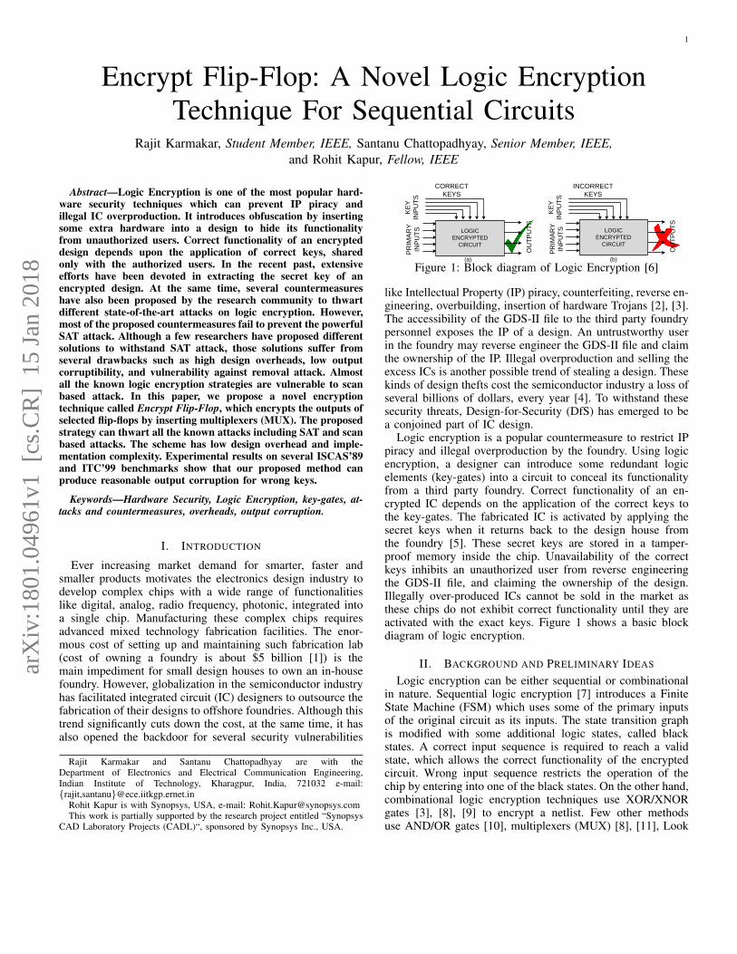
Figure 2: An example of logic encryption. (a) original netlist, (b) encryption using XOR/XNOR gates, (c) encryption using MUX
Up Tables (LUT) [12] as key-gates. The XOR/XNOR basedencryption technique was introduced in EPIC [3]. This methodrandomly inserts XOR/XNOR gates (key-gates) into a design.One input of the XOR/XNOR gate is connected to someinternal line of the circuit, while the other input serves as akey-input. Figure 2(b) shows a typical example of XOR/XNORbased logic encryption which encrypts the circuit of Figure 2(a)using three key-gates, KG1, KG2, and KG3. These key-gatesare configured as buffers upon applying correct keys, else theyinvert the lines, leading to wrong output for invalid keys.
In MUX-based encryption [8], several 2 input-MUXes areinserted into a design. Two different lines (one true line andone false line) of the circuit are connected to the inputs ofa MUX, while the select line of the MUX acts as the key.Correct values of the keys propagate the values at the true linesto the outputs of the MUXes. Figure 2(c) shows an example ofMUX based logic encryption. Another MUX-based encryptionconsiders obfuscation cell (OC) (a combination of a MUX andan inverter) to encrypt a design [11]. In [13], Wang et al. haveproposed an encryption technique which uses a combination ofMUX and camouflage connectors as configurable logic unitsto replace certain logic gates.
To activate an encrypted IC, an unauthorized user mustextract the correct keys. If an IC with M inputs is encryptedwith K keys, a brute force attack requires 2M observationsfrom an active IC and O(2M+K) computations on an encrypteddesign. This is practically impossible for sufficiently largevalues of M and K. Although these methods seem to secure adesign from theft, some later research works have pointed outseveral shortcomings, which can expose a logically encryptedcircuit to several attacks. However, every time a new attack hasbeen proposed, researchers have come forward with a modifiedstrategy to logically encrypt a design, which eventually hasevolved logic encryption techniques towards more secure andbetter ways to thwart different security vulnerabilities.
III. EVOLUTION OF LOGIC ENCRYPTION
One important criterion of logic encryption is that incorrectkeys must produce wrong outputs. This implies that the effectof incorrect keys should propagate to the outputs and corruptsome of the output bits. The EPIC method [3] of logic en-cryption randomly inserts key-gates into the design. However,random insertion of key-gates does not always ensure highoutput corruption for incorrect keys, as the effect of wrongkey may get masked by other inputs, thus, may not propagateto the output. To ensure high output corruption for invalid keys,a fault analysis based key-gate location selection approach hasbeen proposed in [8].
Fault analysis based logic encryption [8]: This methoduses three basic phenomena, fault excitation, fault propagationand fault masking of IC testing to identify several locationsin the circuit, where if any fault occurs (either s-a-0 or s-a-1),propagates to the output and corrupts a maximum number ofoutput bits for most of the applied input patterns. Insertion ofkey-gates in these locations ensures high output corruption forwrong keys.
Although, the fault analysis based technique [8] fulfills thecriterion of high output corruption for wrong keys, some laterresearch works have shown that both random and fault analysisbased key-gate insertion approaches are vulnerable to severalattacks, such as, logic cone analysis [14], hill-climbing [15],path sensitization [9], and SAT-based [16] attacks.
The basic requirements for these attacks are 1) an encryptednetlist, available in the foundry, and 2) a functional IC,available in the market. An attacker applies the same inputto both the circuits and compares the outputs to extract thekeys. Using these attacks an attacker can extract the keys ofan encrypted design.
Logic cone analysis based attack [14]: This attack aimsto minimize the effort of brute force attack by following adivide and conquer strategy to explore the keys. It checks thenumber of key-gates affecting each of the outputs and targetsthe output with the smallest number of key-gates in its inputcone of dependency. A brute force attack on an output whichis affected by the fewest number of key-gates is a feasiblesolution to extract a subpart of the keys. In each iteration, theprocess searches for the outputs with less number of key-gatesin their input cone of dependencies and applies brute force toextract a small portion of the entire key set. To prevent logiccone analysis based attack, Lee et al. have proposed strategicinsertion of some MUXes into the design [14]. The processcreates more overlap between the logic cones, which increasesthe number of key-gates in the input cone of dependency ofeach output.
Hill Climbing Attack [15]: This attack starts by applyingan initial random key to an encrypted netlist and measuringthe Hamming distance between the obtained and the expectedcorrect outputs of a functional chip. With the ultimate goal ofobtaining zero Hamming distance for any set of input patterns,each iteration of the attack takes a decision whether to flip akey-bit or not. The attack succeeds on the finding of such akey which can produce zero Hamming distance between theobserved and the correct outputs for all input patterns.
Path sensitization attack [9]: A key-bit can be sensitizedto the output by selecting specific input pattern if no otherkey-gates interfere in the sensitization path of the key-bit. A
3
similar kind of input pattern is applied to both functional ICand encrypted netlist. Observation of the outputs of these twocircuits can reveal the key values.
Strong logic locking [9]: To prevent path sensitizationattack, Yasin et al. have proposed a strong logic lockingstrategy [9] by inserting key-gates in such locations whichforms a clique where all nodes (key-gates) interfere with eachother. The size of the clique reflects the length of the key. Thisstrategy ensures that sensitization of any key-gate to an outputrequires applying suitable values to the primary inputs as wellas other key inputs. As the other keys are not known to anattacker, no key can be sensitized to the output. One drawbackof this topology dependent key-gate insertion strategy is thatit may not offer ample key-gate locations to encrypt a designwith sufficient number of keys. Moreover, as the key-gates areplaced with an objective to increase the clique size, it does notalways ensure high output corruption for wrong keys.
External key-dependency [6], [17]: To overcome the draw-backs of strong logic locking, Karmakar et al. have proposedan iterative approach which can prevent path sensitizationattack as well as ensure high output corruption for invalidkeys [6]. The nonlinear interdependency among the primaryand secondary keys of this external key-dependency basedencryption strategy helps to thwart both hill climbing andlogic cone based attacks. However, these methods [6], [17]incur some extra hardware to incorporate the key-dependencyunit into the design, which also increases the power and delayoverheads of the design.
SAT-based attack [16]: Recently, a powerful SAT attackwas proposed in [16]. This attack uses a SAT-based algorithmto extract the keys of a logically encrypted combinationalcircuit. The attack algorithm iteratively searches for a specialset of distinguished input patterns (DIPs), which helpto reduce the key search space by eliminating the incorrectkeys. A DIP ensures that at least two different keys producedifferent outputs. Comparison of the outputs with the outputof a functional chip, for the same DIP , helps to eliminateat least one or both the keys as incorrect keys. The attackshows that using a limited number of DIPs, all the incorrectkeys can be eliminated and an equivalent set of correct keyscan be revealed. Another SAT-based attack called AppSATwas proposed in [18], which can approximately deobfuscatean encrypted netlist with very low error rate.
SAT-resilient techniques: The complexity of SAT-basedattack depends on the complexity of the circuit as well asthe number of DIP s required to eliminate all the wrong keys.To prevent SAT attack, Yasin et al. have proposed to integratesome extra hardware (called SARLock) [19] with strong logiclocking [9], that increases the effort of SAT attack by expo-nentially increasing the number of DIPs to eliminate all theincorrect keys. The proposed SARLock method modifies theoutputs in such a way that an incorrect key produces a wrongoutput only for a specific input pattern. Therefore, a DIP caneliminate only one incorrect key. For a sufficiently long key, theexponential number of required DIP s makes the SAT attackimpossible. However, some later research [20] has shown thatSARLock is vulnerable to removal attack. To mitigate theremoval attack, Yasin et al. have proposed a new SAT-resilient
encryption technique called TTLock [20] which modifies alogic cone by flipping the output for a secret input pattern andrestores the flip for correct keys. Another SAT-based attackcalled Double DIP [21] has been proposed in recent time,which can avoid the exponential iteration of key search processincorporated by the SARLock method. Yang et al. have alsoproposed to use an Anti-SAT block [22] to exponentiallyincrease the number of SAT attack iterations to reveal thecorrect key. However, the security of Anti-SAT block can bebypassed using a Signal Probability Skew (SPS) attack [23]. In[24], Xu et al. have also shown that both SARLock and Anti-SAT are vulnerable to a new bypass attack. In [25], Xie et al.have proposed to use tunable delay key-gates (TDK) to encrypta design. The proposed Delay Locking strategy considers twokeys for each TDK, one for functional locking and the otherfor manipulating the delay. The introduction of timing violationfor wrong delay keys helps this method to thwart SAT attack.Another SAT-resilient secure cell design technique has beenproposed in [26]. A cyclic obfuscation based SAT-resilienceencryption technique has been proposed in [27], which createslogical loop in a circuit by adding dummy wires and gates.The approach ensures that all the inserted cycles have multipleways to open. As the circuit can no longer be represented asa directed acyclic graph (DAG), the conventional SAT-basedattack cannot be applied to extract the keys. However, Zhou etal. recently proposed an algorithm called CycSAT [28], whichcan effectively decrypt cyclic obfuscation.
In recent times, several transistor level logic encryptiontechniques have been proposed in [29], [30]. Chen et al.have proposed a low overhead gate replacement technique [31]for logic encryption. The proposed technique can significantlyreduce the area, power, and delay overheads, compared tothe typical XOR/XNOR based encryption, however, it fails tothwart SAT attack.
IV. MOTIVATION AND CONTRIBUTION OF THE PAPER
In the previous section, we have observed several short-comings of different logic encryption strategies. For example,strong logic locking [9] can thwart path sensitization andhill climbing attacks, however, sometimes fails to encrypt adesign with a sufficiently large number of keys. Similarly,external key-dependency based approach [6] prevents pathsensitization, hill climbing, and logic cone based attacks atthe cost of higher hardware, power, and delay overheads,compared to other methods. We have also observed that mostof the logic encryption strategies are vulnerable to SAT-based attack. Although the SARLock [19] and Anti-SAT [22]methods restrict the SAT attack, they require extra hardwareto increase the effort of SAT-attack. The SARLock methodmodifies a design in such a way that even for a wrong key, thecircuit produces correct output for most of the inputs, whichmay not be a desirable criterion from a designer’s point ofview. Moreover, both SARLcok and Anti-SAT methods arevulnerable to removal attack. Most of the existing logic en-cryption strategies fail to prevent all the known state-of-the-artattacks while simultaneously fulfilling the basic requirementslike high output corruptibility, low design overhead and low
4
implementation complexity. These observations clearly showthat despite a substantial amount of research, logic encryptionmethods are yet to get matured enough, which leaves roomfor further improvements. The demand for a low overhead andsecured way to logically encrypt a design has motivated us todevelop a new logic encryption strategy.
The main contributions of the paper are as follows.1) We propose a scan based attack which exploits the DfT
infrastructure to partition a circuit into multiple smallersub-circuits and attack them individually. The attack candrastically reduce the complexity of any state-of-the-artattack on any logically encrypted sequential circuit.
2) To prevent the proposed attack, we introduce a newlogic encryption strategy, which encrypts the outputs ofthe flip-flops. The proposed Encrypt Flip-flop strategyensures that the scan chains do not leak any keyinformation, thus, prevent scan based attack.
3) The proposed encryption strategy restricts the control-lability and observability of the flip-flops of the scanchains. This inhibits an attacker to apply SAT-basedattack by converting a sequential design to a combina-tional one using scan facility. Unlike other methods ourmethod does not incur any extra hardware to preventSAT attack.
4) The proposed low overhead encryption strategy can alsoprevent other state-of-the-art attacks, like path sensiti-zation, hill climbing, and logic cone based attacks.
V. PROPOSED SCAN BASED ATTACK ON LOGICENCRYPTION
In this section, we present an attack on conventional logicencryption techniques, which uses the phenomenon of scanbased side channel attack. We show that the scan chains of adesign can be exploited to drastically reduce the complexityof several state-of-the-art attacks on logic encryption.
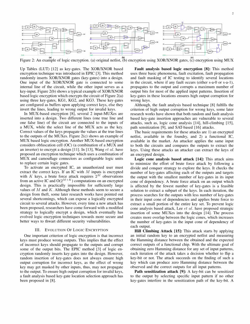
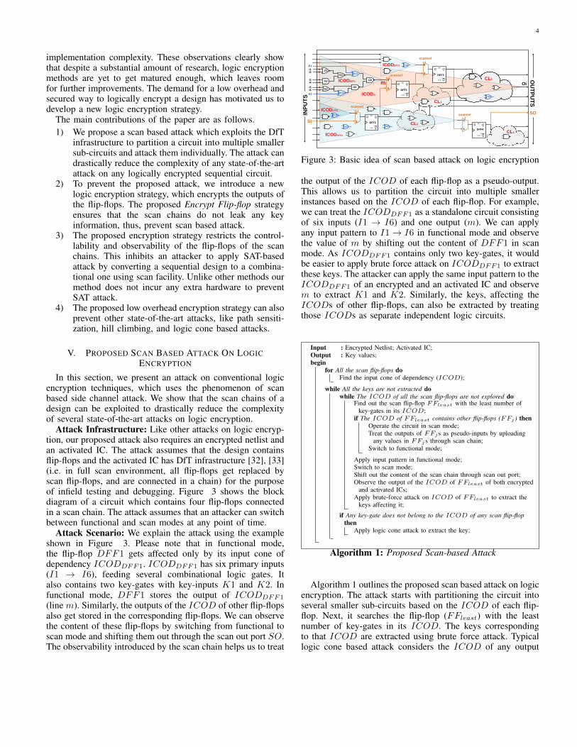
Attack Infrastructure: Like other attacks on logic encryp-tion, our proposed attack also requires an encrypted netlist andan activated IC. The attack assumes that the design containsflip-flops and the activated IC has DfT infrastructure [32], [33](i.e. in full scan environment, all flip-flops get replaced byscan flip-flops, and are connected in a chain) for the purposeof infield testing and debugging. Figure 3 shows the blockdiagram of a circuit which contains four flip-flops connectedin a scan chain. The attack assumes that an attacker can switchbetween functional and scan modes at any point of time.
Attack Scenario: We explain the attack using the exampleshown in Figure 3. Please note that in functional mode,the flip-flop DFF1 gets affected only by its input cone ofdependency ICODDFF1. ICODDFF1 has six primary inputs(I1 → I6), feeding several combinational logic gates. Italso contains two key-gates with key-inputs K1 and K2. Infunctional mode, DFF1 stores the output of ICODDFF1
(line m). Similarly, the outputs of the ICOD of other flip-flopsalso get stored in the corresponding flip-flops. We can observethe content of these flip-flops by switching from functional toscan mode and shifting them out through the scan out port SO.The observability introduced by the scan chain helps us to treat
Q
QSET
CLR
D
DFF1
Q
QSET
CLR
D
DFF2
Q
QSET
CLR
D
DFF3
Q
QSET
CLR
D
DFF4
G1
G2
G4KG1
G3G5
G6
KG2
KG
0
1
0
1
0
1
0
1
scansel
scansel
scansel
scansel
ICODDFF1
ICODDFF2
ICODDFF4
ICODDFF3
CL1
CL2
CL3
CL4
KG
OU
TP
UT
S
INP
UT
S
I1I2
I3I4
I5I6
K2
K1
SO
SI
m Oi
ICODOi
KG
KG
KG
Figure 3: Basic idea of scan based attack on logic encryption
the output of the ICOD of each flip-flop as a pseudo-output.This allows us to partition the circuit into multiple smallerinstances based on the ICOD of each flip-flop. For example,we can treat the ICODDFF1 as a standalone circuit consistingof six inputs (I1 → I6) and one output (m). We can applyany input pattern to I1→ I6 in functional mode and observethe value of m by shifting out the content of DFF1 in scanmode. As ICODDFF1 contains only two key-gates, it wouldbe easier to apply brute force attack on ICODDFF1 to extractthese keys. The attacker can apply the same input pattern to theICODDFF1 of an encrypted and an activated IC and observem to extract K1 and K2. Similarly, the keys, affecting theICODs of other flip-flops, can also be extracted by treatingthose ICODs as separate independent logic circuits.
Input : Encrypted Netlist; Activated IC;Output : Key values;begin
for All the scan flip-flops doFind the input cone of dependency (ICOD);
while All the keys are not extracted dowhile The ICOD of all the scan flip-flops are not explored do
Find out the scan flip-flop FFleast with the least number ofkey-gates in its ICOD;
if The ICOD of FFleast contains other flip-flops (FFj ) thenOperate the circuit in scan mode;Treat the outputs of FFjs as pseudo-inputs by uploading
any values in FFjs through scan chain;Switch to functional mode;
Apply input pattern in functional mode;Switch to scan mode;Shift out the content of the scan chain through scan out port;Observe the output of the ICOD of FFleast of both encrypted
and activated ICs;Apply brute-force attack on ICOD of FFleast to extract the
keys affecting it;
if Any key-gate does not belong to the ICOD of any scan flip-flopthen
Apply logic cone attack to extract the key;
Algorithm 1: Proposed Scan-based Attack
Algorithm 1 outlines the proposed scan based attack on logicencryption. The attack starts with partitioning the circuit intoseveral smaller sub-circuits based on the ICOD of each flip-flop. Next, it searches the flip-flop (FFleast) with the leastnumber of key-gates in its ICOD. The keys correspondingto that ICOD are extracted using brute force attack. Typicallogic cone based attack considers the ICOD of any output
5
to perform the attack. We can observe from Figure 3 that theinput cone of dependency ICODOi of the output Oi containsmore primary inputs, logic gates, and key-gates comparedto the ICOD of any flip-flop. As the complexity of bruteforce attack exponentially increases with the number of key-gates and the size of a circuit, it is much easier to applythe attack on the ICOD of any flip-flop compared to thatof any output. The attack iteratively searches for the flip-flopwith the least number of key-gates (FFleast) in its ICODand extract those keys. A brute force attack on an ICODwhich contains only combinational elements is straightforward.However, if the ICOD of FFleast contains other flip-flops(say FFjs), an attacker has to operate the circuit in scanmode to use the outputs of the FFjs as pseudo-primary inputsbefore switching back to the functional mode of operation.For example, DFF4 contains DFF2 in its input cone ofdependency ICODDFF4. Therefore, at the time of extractingthe keys present in ICODDFF4, first, we operate the circuitin scan mode and upload any value to DFF2 and then switchto functional mode. This mutes the ICODDFF2 and reducesthe ICOD of DFF4 from ICODDFF4 to (ICODDFF4 -ICODDFF2).
The attack can be applied to any state-of-the-art logicencryption technique provided the circuit contains flip-flopswith DfT infrastructure for infield testing. The complexity ofthe attack does not depend on the total number of key-gatesand primary inputs. Rather it depends on the number of key-gates present in the largest ICOD of any flip-flop and thenumber of primary inputs affecting that ICOD. If the largestICOD of any flip-flop contains K1 key-gates and M1 primaryinputs, the complexity of the attack reduces from O(2M+K) toO(2M1+K1). In general, K1 � K and M1 < M , therefore,it becomes easy to apply the attack on a large complex circuit,encrypted with a sufficiently large number of keys.
To examine the effectiveness of scan based attack, wehave applied the attack on several ISCAS’89 and ITC’99benchmarks, which are encrypted using typical XOR/XNORbased encryption strategy (128-bit key). Table I reports thecomplexities of both scan-based and brute force attacks (inthe format, scan attack complexity / brute force complexity)on different ISCAS’89 and ITC’99 benchmarks. We observethat the scan based attack can drastically reduce the attackcomplexity. For example, the brute force attack complexity ons15850 is 2128+77 = 2205, which can be reduced down to 262
by exploiting the scan chains of the design. This makes severalother attacks feasible, which would not have been possibleotherwise. This attack shows the importance of introductionof encryption in scan chains, which has not been consideredin the literature.
VI. ENCRYPT FLIP-FLOP: A NEW LOGIC ENCRYPTIONSTRATEGY
In the previous section, we have shown that any state-of-the-art logic encryption technique is vulnerable to scan basedattack. To restrict the leakage of information through the scanchain, we propose to introduce obfuscation in the scan chainitself. In this section, we propose a new logic encryptionstrategy called Encrypt Flip-Flop, which encrypts the outputs
Table I: Complexity of scan attack on several ISCAS’89 andITC’99 benchmarks (K = 123 for s9234, K = 128 for others)
CircuitName
Attack complexityScan / Brute Force
CircuitName
Attack complexityScan / Brute Force
s5378 266 / 2163 b17 261 / 2165
s9234 251 / 2159 b18 247 / 2165
s13207 256 / 2190 b19 251 / 2152
s15850 262 / 2205 b20 264 / 2160
s38417 269 / 2156 b21 258 / 2160
s38584 274 / 2166 b22 253 / 2160
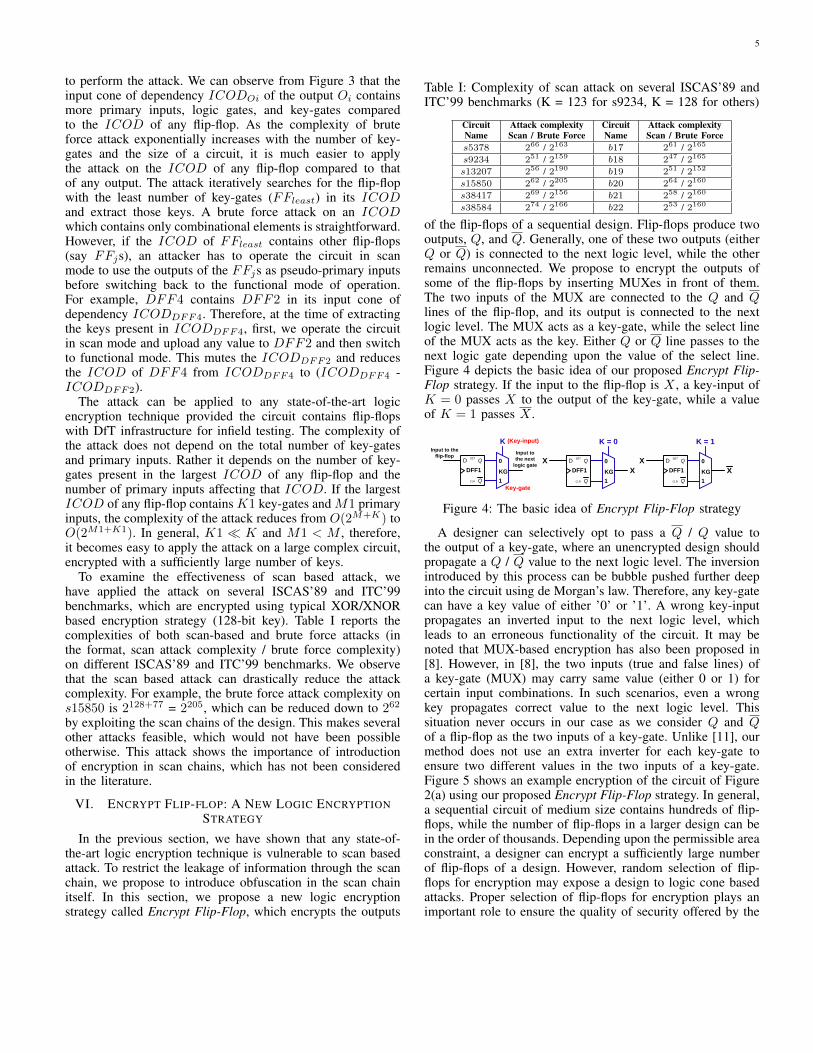
of the flip-flops of a sequential design. Flip-flops produce twooutputs, Q, and Q. Generally, one of these two outputs (eitherQ or Q) is connected to the next logic level, while the otherremains unconnected. We propose to encrypt the outputs ofsome of the flip-flops by inserting MUXes in front of them.The two inputs of the MUX are connected to the Q and Qlines of the flip-flop, and its output is connected to the nextlogic level. The MUX acts as a key-gate, while the select lineof the MUX acts as the key. Either Q or Q line passes to thenext logic gate depending upon the value of the select line.Figure 4 depicts the basic idea of our proposed Encrypt Flip-Flop strategy. If the input to the flip-flop is X , a key-input ofK = 0 passes X to the output of the key-gate, while a valueof K = 1 passes X .
Q
QSET
CLR
D
DFF1
0
1
K
KG
Input to the
flip-flopInput to
the next
logic gate
Key-gate
(Key-input)
Q
QSET
CLR
D
DFF1
0
1
K = 0
KG
X
X
Q
QSET
CLR
D
DFF1
0
1
K = 1
KG
X
X
Figure 4: The basic idea of Encrypt Flip-Flop strategy
A designer can selectively opt to pass a Q / Q value tothe output of a key-gate, where an unencrypted design shouldpropagate a Q / Q value to the next logic level. The inversionintroduced by this process can be bubble pushed further deepinto the circuit using de Morgan’s law. Therefore, any key-gatecan have a key value of either ’0’ or ’1’. A wrong key-inputpropagates an inverted input to the next logic level, whichleads to an erroneous functionality of the circuit. It may benoted that MUX-based encryption has also been proposed in[8]. However, in [8], the two inputs (true and false lines) ofa key-gate (MUX) may carry same value (either 0 or 1) forcertain input combinations. In such scenarios, even a wrongkey propagates correct value to the next logic level. Thissituation never occurs in our case as we consider Q and Qof a flip-flop as the two inputs of a key-gate. Unlike [11], ourmethod does not use an extra inverter for each key-gate toensure two different values in the two inputs of a key-gate.Figure 5 shows an example encryption of the circuit of Figure2(a) using our proposed Encrypt Flip-Flop strategy. In general,a sequential circuit of medium size contains hundreds of flip-flops, while the number of flip-flops in a larger design can bein the order of thousands. Depending upon the permissible areaconstraint, a designer can encrypt a sufficiently large numberof flip-flops of a design. However, random selection of flip-flops for encryption may expose a design to logic cone basedattacks. Proper selection of flip-flops for encryption plays animportant role to ensure the quality of security offered by the
6
encrypted design.
G1G3
G6
G5
G4
G8
G2
G9G10
G13
G14
G11
G12
Q
QSET
CLR
D
DFF1
Q
QSET
CLR
D
DFF4
Q
QSET
CLR
D
DFF3
Q
QSET
CLR
D
DFF2
I1
I2
I3
I4
I5
I6
O1
O2
CLK
0
1
K2
KG
2
0
1
K1
KG
1
I7
I8
I9G7
Figure 5: Encrypting the example circuit of Figure 2(a) usingEncrypt Flip-Flop strategy
A. Selection Of Flip-flops For EncryptionWe have observed in Section III that the vulnerability of
a circuit against logic cone based attack increases if someoutputs of the circuit do not contain a sufficient number ofkey-gates in their input cone of dependency. Therefore, theprimary focus of our key-gate location selection process is toconfine the effects of all the key-gates to a limited numberof outputs, and at the same time, ensuring that each of theaffected outputs contains all the key-gates in its input cone ofdependency. Let us assume, a circuit consists of M inputs, Ooutputs and L flip-flops. We would like to encrypt the circuitusing a K-bit key. We will select K out of L flip-flops, whichsatisfy the following criterion.
Each of the outputs, affected by any of these K flip-flops, must contain all of these K flip-flops in its inputcone of dependency.
We encrypt these K flip-flops by inserting a MUX in frontof each of them. The select lines of these MUXes act as key-inputs. The process ensures that the input cone of dependencyof any output contains either all or none of the key-gates. Noneof the outputs contains only few key-gates in its input cone ofdependency. Thus, an attacker does not get an opportunity tominimize the effort of brute force search by employing logiccone based attack.
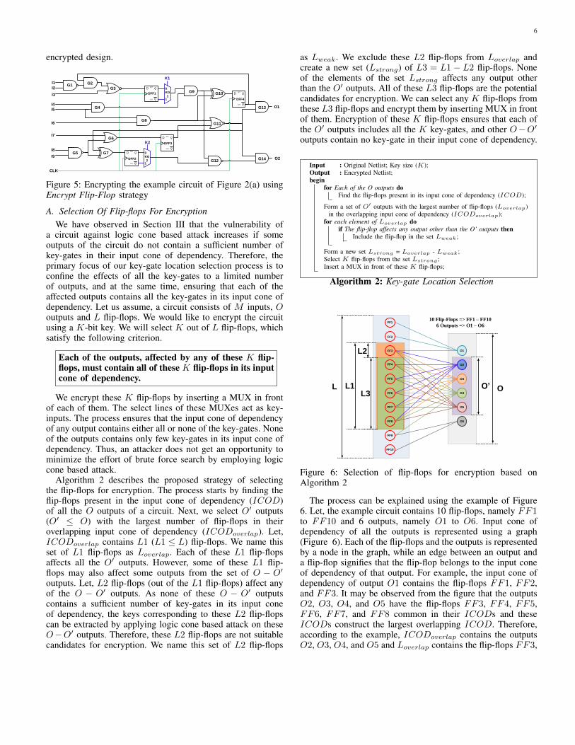
Algorithm 2 describes the proposed strategy of selectingthe flip-flops for encryption. The process starts by finding theflip-flops present in the input cone of dependency (ICOD)of all the O outputs of a circuit. Next, we select O′ outputs(O′ ≤ O) with the largest number of flip-flops in theiroverlapping input cone of dependency (ICODoverlap). Let,ICODoverlap contains L1 (L1 ≤ L) flip-flops. We name thisset of L1 flip-flops as Loverlap. Each of these L1 flip-flopsaffects all the O′ outputs. However, some of these L1 flip-flops may also affect some outputs from the set of O − O′
outputs. Let, L2 flip-flops (out of the L1 flip-flops) affect anyof the O − O′ outputs. As none of these O − O′ outputscontains a sufficient number of key-gates in its input coneof dependency, the keys corresponding to these L2 flip-flopscan be extracted by applying logic cone based attack on theseO−O′ outputs. Therefore, these L2 flip-flops are not suitablecandidates for encryption. We name this set of L2 flip-flops
as Lweak. We exclude these L2 flip-flops from Loverlap andcreate a new set (Lstrong) of L3 = L1− L2 flip-flops. Noneof the elements of the set Lstrong affects any output otherthan the O′ outputs. All of these L3 flip-flops are the potentialcandidates for encryption. We can select any K flip-flops fromthese L3 flip-flops and encrypt them by inserting MUX in frontof them. Encryption of these K flip-flops ensures that each ofthe O′ outputs includes all the K key-gates, and other O−O′
outputs contain no key-gate in their input cone of dependency.
Input : Original Netlist; Key size (K);Output : Encrypted Netlist;begin
for Each of the O outputs doFind the flip-flops present in its input cone of dependency (ICOD);
Form a set of O′ outputs with the largest number of flip-flops (Loverlap)in the overlapping input cone of dependency (ICODoverlap);
for each element of Loverlap doif The flip-flop affects any output other than the O’ outputs then
Include the flip-flop in the set Lweak;
Form a new set Lstrong = Loverlap - Lweak;Select K flip-flops from the set Lstrong ;Insert a MUX in front of these K flip-flops;
Algorithm 2: Key-gate Location Selection
O2
O4
O1
O3
O5
O6
FF1
FF2
FF3
FF4
FF5
FF6
FF7
FF8
FF9
FF10
L L1L3
L2
O’ O
10 Flip-Flops => FF1 – FF10
6 Outputs => O1 – O6
Figure 6: Selection of flip-flops for encryption based onAlgorithm 2
The process can be explained using the example of Figure6. Let, the example circuit contains 10 flip-flops, namely FF1to FF10 and 6 outputs, namely O1 to O6. Input cone ofdependency of all the outputs is represented using a graph(Figure 6). Each of the flip-flops and the outputs is representedby a node in the graph, while an edge between an output anda flip-flop signifies that the flip-flop belongs to the input coneof dependency of that output. For example, the input cone ofdependency of output O1 contains the flip-flops FF1, FF2,and FF3. It may be observed from the figure that the outputsO2, O3, O4, and O5 have the flip-flops FF3, FF4, FF5,FF6, FF7, and FF8 common in their ICODs and theseICODs construct the largest overlapping ICOD. Therefore,according to the example, ICODoverlap contains the outputsO2, O3, O4, and O5 and Loverlap contains the flip-flops FF3,
7
FF4, FF5, FF6, FF7, and FF8. Please note that the flip-flop FF3 also affects the output O1 which is not an element ofthe list O′. If we encrypt the output of FF3, it would be easierto extract the corresponding key by applying logic cone basedattack on the output O1. Therefore, the flip-flop FF3 belongsto the set Lweak. We exclude FF3 from Loverlap and constructthe set Lstrong which contains the flip-flops FF4, FF5, FF6,FF7, and FF8. It may be noted that every element of Lstrong
affects only the outputs of the list O′. Encryption of the flip-flops of the set Lstrong ensures protection against logic conebased attack.
VII. SECURITY ANALYSIS
In this section, we evaluate the security of our proposedapproach against several attacks proposed in the literature. Wehave already discussed about sustainability against logic coneanalysis based attack [14]. Therefore, we mainly focus on othersecurity threats like path sensitization attack [9], scan basedattack, SAT attack [16] etc.
A. Security Evaluation Against Path Sensitization AttackIn this section, we examine whether a path sensitization
attack can be performed on a design encrypted using ourproposed strategy. Path sensitization attack on the proposedlogic encryption is slightly different from the attack proposedin [9]. Unlike [9], we cannot directly propagate a key-valueto an output. Rather, we have to apply a specific value to theinput of an encrypted flip-flop and propagate that value to theoutput by selecting a key-value (either 0 or 1). Comparison ofthe output with the output of an activated IC decides whetherthe applied key is correct or wrong. Therefore, to perform pathsensitization attack, it is important to control the input of anencrypted flip-flop. Input of a flip-flop can be controlled intwo ways. Input of few flip-flops can be directly controlled bymanipulating the primary inputs (although the number of suchflip-flop is very less). Inputs of the rest of the flip-flops can alsobe controlled, provided an activated IC has the scan facility forthe purpose of in-field testing. This is very common as mostof the ICs have the DfT (Design-for-Testability) infrastructure.
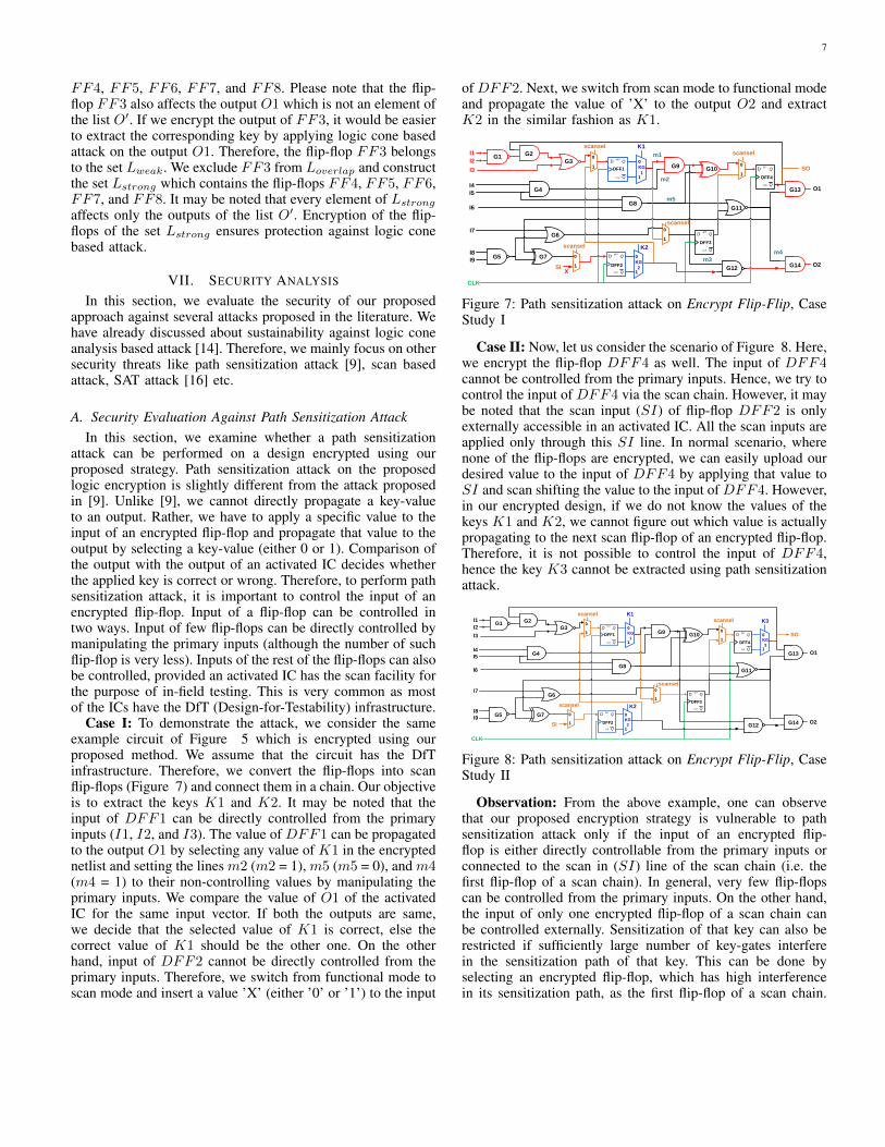
Case I: To demonstrate the attack, we consider the sameexample circuit of Figure 5 which is encrypted using ourproposed method. We assume that the circuit has the DfTinfrastructure. Therefore, we convert the flip-flops into scanflip-flops (Figure 7) and connect them in a chain. Our objectiveis to extract the keys K1 and K2. It may be noted that theinput of DFF1 can be directly controlled from the primaryinputs (I1, I2, and I3). The value of DFF1 can be propagatedto the output O1 by selecting any value of K1 in the encryptednetlist and setting the lines m2 (m2 = 1), m5 (m5 = 0), and m4(m4 = 1) to their non-controlling values by manipulating theprimary inputs. We compare the value of O1 of the activatedIC for the same input vector. If both the outputs are same,we decide that the selected value of K1 is correct, else thecorrect value of K1 should be the other one. On the otherhand, input of DFF2 cannot be directly controlled from theprimary inputs. Therefore, we switch from functional mode toscan mode and insert a value ’X’ (either ’0’ or ’1’) to the input
of DFF2. Next, we switch from scan mode to functional modeand propagate the value of ’X’ to the output O2 and extractK2 in the similar fashion as K1.
G1G3
G6
G5
G4
G8
G2
G9G10
G14
G11
G12
Q
QSET
CLR
D
DFF1
Q
QSET
CLR
D
DFF4
Q
QSET
CLR
D
DFF3
Q
QSET
CLR
D
DFF2
I1
I2
I3
I8
I9
O1
O2
CLK
0
1
K2
KG
2
0
1
K1
KG
1
0
1
scansel
m3
m4
m2I4
I5
I6
m1
I7
m5
X
G7
0
1
0
1
0
1
scansel
scanselscansel
SI
SO
G13
Figure 7: Path sensitization attack on Encrypt Flip-Flip, CaseStudy I
Case II: Now, let us consider the scenario of Figure 8. Here,we encrypt the flip-flop DFF4 as well. The input of DFF4cannot be controlled from the primary inputs. Hence, we try tocontrol the input of DFF4 via the scan chain. However, it maybe noted that the scan input (SI) of flip-flop DFF2 is onlyexternally accessible in an activated IC. All the scan inputs areapplied only through this SI line. In normal scenario, wherenone of the flip-flops are encrypted, we can easily upload ourdesired value to the input of DFF4 by applying that value toSI and scan shifting the value to the input of DFF4. However,in our encrypted design, if we do not know the values of thekeys K1 and K2, we cannot figure out which value is actuallypropagating to the next scan flip-flop of an encrypted flip-flop.Therefore, it is not possible to control the input of DFF4,hence the key K3 cannot be extracted using path sensitizationattack.
G1G3
G6
G5
G4
G8
G2
G9G10
G14
G11
G12
Q
QSET
CLR
D
DFF1
Q
QSET
CLR
D
DFF4
Q
QSET
CLR
D
DFF3
Q
QSET
CLR
D
DFF2
I1
I2
I3
I8
I9
O1
O2
CLK
0
1
K2
KG
2
0
1
K1
KG
1
0
1
scansel
I4
I5
I6
I7
G7
0
1
0
1
0
1
scansel
scanselscansel
SI
G13
0
1
K3
KG
3
SO
Figure 8: Path sensitization attack on Encrypt Flip-Flip, CaseStudy II
Observation: From the above example, one can observethat our proposed encryption strategy is vulnerable to pathsensitization attack only if the input of an encrypted flip-flop is either directly controllable from the primary inputs orconnected to the scan in (SI) line of the scan chain (i.e. thefirst flip-flop of a scan chain). In general, very few flip-flopscan be controlled from the primary inputs. On the other hand,the input of only one encrypted flip-flop of a scan chain canbe controlled externally. Sensitization of that key can also berestricted if sufficiently large number of key-gates interferein the sensitization path of that key. This can be done byselecting an encrypted flip-flop, which has high interferencein its sensitization path, as the first flip-flop of a scan chain.
8
Q
QSET
CLR
D
DFF4
Q
QSET
CLR
D
DFF6
Q
QSET
CLR
D
DFF7
Q
QSET
CLR
D
DFF2
Q
QSET
CLR
D
DFF10
Q
QSET
CLR
D
DFF5
Q
QSET
CLR
D
DFF1
Q
QSET
CLR
D
DFF8
Q
QSET
CLR
D
DFF3
Q
QSET
CLR
D
DFF9
COMBINATIONAL UNIT
0
1
0
1
0
1
0
1
0
1
0
1
0
1
0
1
0
1
0
1
0
1
0
1
0
1
0
1
0
1
K2 K3K1 K4 K5
CLK
SI
1
SO
KG1 KG2 KG3 KG4 KG5
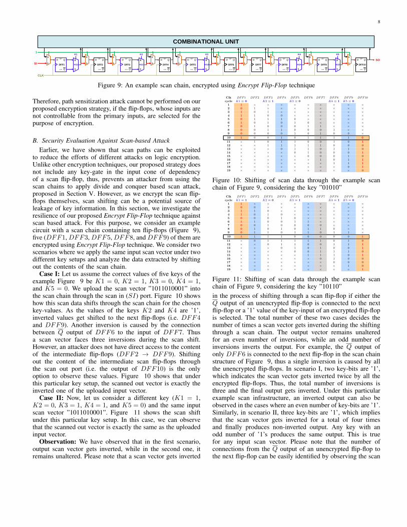
Figure 9: An example scan chain, encrypted using Encrypt Flip-Flop technique
Therefore, path sensitization attack cannot be performed on ourproposed encryption strategy, if the flip-flops, whose inputs arenot controllable from the primary inputs, are selected for thepurpose of encryption.
B. Security Evaluation Against Scan-based AttackEarlier, we have shown that scan paths can be exploited
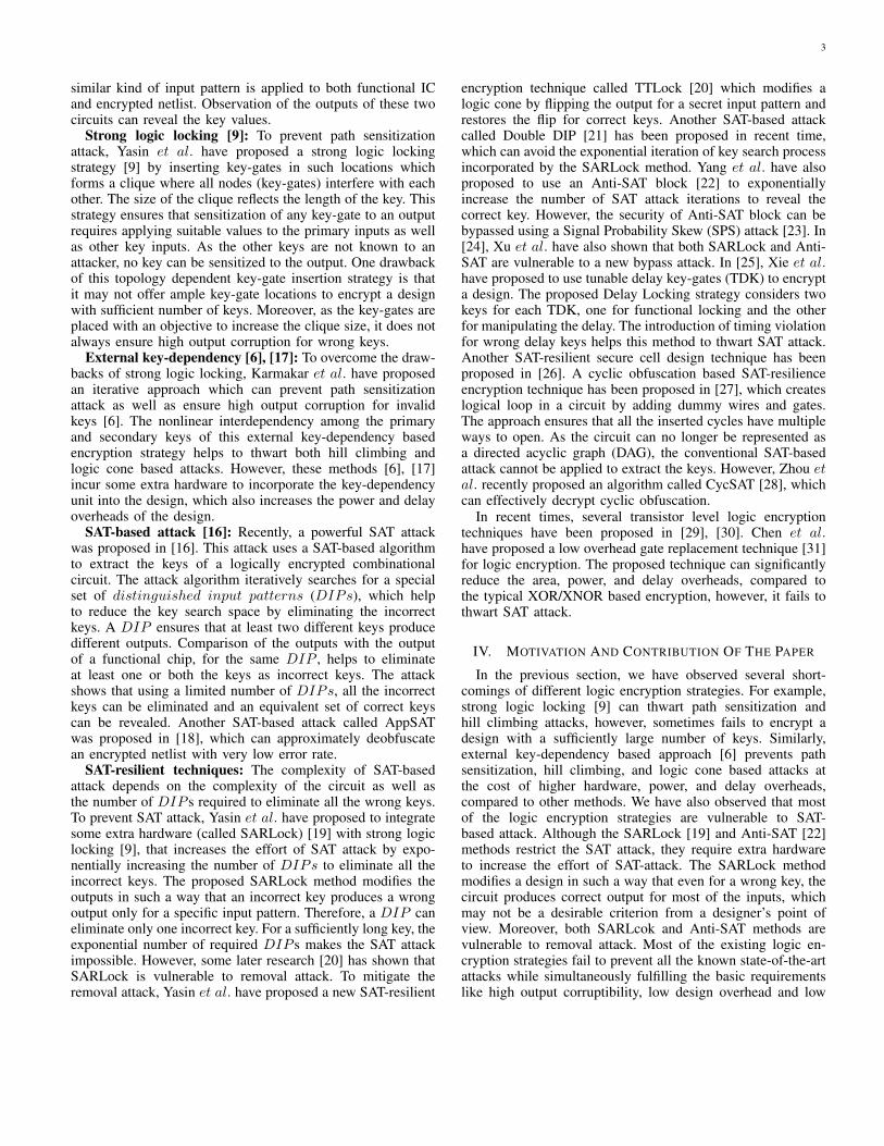
to reduce the efforts of different attacks on logic encryption.Unlike other encryption techniques, our proposed strategy doesnot include any key-gate in the input cone of dependencyof a scan flip-flop, thus, prevents an attacker from using thescan chains to apply divide and conquer based scan attack,proposed in Section V. However, as we encrypt the scan flip-flops themselves, scan shifting can be a potential source ofleakage of key information. In this section, we investigate theresilience of our proposed Encrypt Flip-Flop technique againstscan based attack. For this purpose, we consider an examplecircuit with a scan chain containing ten flip-flops (Figure 9),five (DFF1, DFF3, DFF5, DFF8, and DFF9) of them areencrypted using Encrypt Flip-Flop technique. We consider twoscenarios where we apply the same input scan vector under twodifferent key setups and analyze the data extracted by shiftingout the contents of the scan chain.
Case I: Let us assume the correct values of five keys of theexample Figure 9 be K1 = 0, K2 = 1, K3 = 0, K4 = 1,and K5 = 0. We upload the scan vector ”1011010001” intothe scan chain through the scan in (SI) port. Figure 10 showshow this scan data shifts through the scan chain for the chosenkey-values. As the values of the keys K2 and K4 are ’1’,inverted values get shifted to the next flip-flops (i.e. DFF4and DFF9). Another inversion is caused by the connectionbetween Q output of DFF6 to the input of DFF7. Thusa scan vector faces three inversions during the scan shift.However, an attacker does not have direct access to the contentof the intermediate flip-flops (DFF2 → DFF9). Shiftingout the content of the intermediate scan flip-flops throughthe scan out port (i.e. the output of DFF10) is the onlyoption to observe these values. Figure 10 shows that underthis particular key setup, the scanned out vector is exactly theinverted one of the uploaded input vector.
Case II: Now, let us consider a different key (K1 = 1,K2 = 0, K3 = 1, K4 = 1, and K5 = 0) and the same inputscan vector ”1011010001”. Figure 11 shows the scan shiftunder this particular key setup. In this case, we can observethat the scanned out vector is exactly the same as the uploadedinput vector.
Observation: We have observed that in the first scenario,output scan vector gets inverted, while in the second one, itremains unaltered. Please note that a scan vector gets inverted
DFF1 DFF2 DFF3 DFF4 DFF5 DFF6 DFF7 DFF8 DFF9 DFF10Clkcycle K1 = 0 K2 = 1 K3 = 0 K4 = 1 K5 = 01 1 × × × × × × × × ×2 0 1 × × × × × × × ×3 1 0 1 × × × × × × ×4 1 1 0 0 × × × × × ×5 0 1 1 1 0 × × × × ×6 1 0 1 0 1 0 × × × ×7 0 1 0 0 0 1 1 × × ×8 0 0 1 1 0 0 0 1 × ×9 0 0 0 0 1 0 1 0 0 ×10 1 0 0 1 0 1 1 1 1 0
11 × 1 0 1 1 0 0 1 0 112 × × 1 1 1 1 1 0 0 013 × × × 0 1 1 0 1 1 014 × × × × 0 1 0 0 0 115 × × × × × 0 0 0 1 016 × × × × × × 1 0 1 117 × × × × × × × 1 1 118 × × × × × × × × 0 119 × × × × × × × × × 0
Figure 10: Shifting of scan data through the example scanchain of Figure 9, considering the key ”01010”
DFF1 DFF2 DFF3 DFF4 DFF5 DFF6 DFF7 DFF8 DFF9 DFF10Clkcycle K1 = 1 K2 = 0 K3 = 1 K4 = 1 K5 = 01 1 × × × × × × × × ×2 0 0 × × × × × × × ×3 1 1 0 × × × × × × ×4 1 0 1 0 × × × × × ×5 0 0 0 1 0 × × × × ×6 1 1 0 0 1 1 × × × ×7 0 0 1 0 0 0 0 × × ×8 0 1 0 1 0 1 1 0 × ×9 0 1 1 0 1 1 0 1 1 ×10 1 1 1 1 0 0 0 0 0 1
11 × 0 1 1 1 1 1 0 1 012 × × 0 1 1 0 0 1 1 113 × × × 0 1 0 1 0 0 114 × × × × 0 0 1 1 1 015 × × × × × 1 1 1 0 116 × × × × × × 0 1 0 017 × × × × × × × 0 0 018 × × × × × × × × 1 019 × × × × × × × × × 1
Figure 11: Shifting of scan data through the example scanchain of Figure 9, considering the key ”10110”in the process of shifting through a scan flip-flop if either theQ output of an unencrypted flip-flop is connected to the nextflip-flop or a ’1’ value of the key-input of an encrypted flip-flopis selected. The total number of these two cases decides thenumber of times a scan vector gets inverted during the shiftingthrough a scan chain. The output vector remains unalteredfor an even number of inversions, while an odd number ofinversions inverts the output. For example, the Q output ofonly DFF6 is connected to the next flip-flop in the scan chainstructure of Figure 9, thus a single inversion is caused by allthe unencrypted flip-flops. In scenario I, two key-bits are ’1’,which indicates the scan vector gets inverted twice by all theencrypted flip-flops. Thus, the total number of inversions isthree and the final output gets inverted. Under this particularexample scan infrastructure, an inverted output can also beobserved in the cases where an even number of key-bits are ’1’.Similarly, in scenario II, three key-bits are ’1’, which impliesthat the scan vector gets inverted for a total of four timesand finally produces non-inverted output. Any key with anodd number of ’1’s produces the same output. This is truefor any input scan vector. Please note that the number ofconnections from the Q output of an unencrypted flip-flop tothe next flip-flop can be easily identified by observing the scan
9
chain structure. However, it is not possible to figure out thenumber of ’1’s present in a key by observing the output vector.Therefore, an output scan vector can only identify whethera key contains an even or an odd number of ’1’s in it. Itdoes not reveal any information regarding the number of ’1’spresent in a key. A K bit key has 2K−1 possible combinationof keys, where an even number of bits are ’1’, and 2K−1
possible combination of keys, where an odd number of bitsare ’1’. For example, out of the 32 possible key combinations,16 key combinations of the Figure 9 have either an even or anodd number of ’1’s. Therefore, by observing the type of scanoutput, an attacker can eliminate 2K−1 possible combinationof keys which can only reduce the complexity of a brute forceattack from O(2M+K) to O(2M+(K−1)).
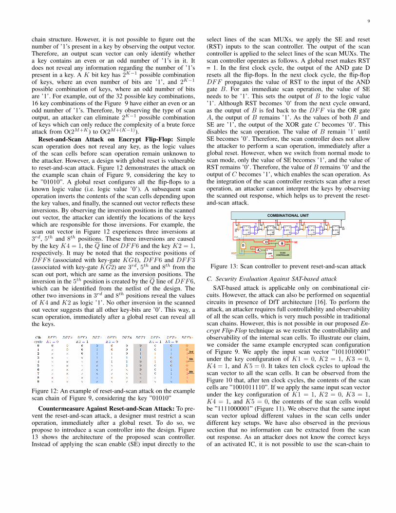
Reset-and-Scan Attack on Encrypt Flip-Flop: Simplescan operation does not reveal any key, as the logic valuesof the scan cells before scan operation remain unknown tothe attacker. However, a design with global reset is vulnerableto reset-and-scan attack. Figure 12 demonstrates the attack onthe example scan chain of Figure 9, considering the key tobe ”01010”. A global reset configures all the flip-flops to aknown logic value (i.e. logic value ’0’). A subsequent scanoperation inverts the contents of the scan cells depending uponthe key values, and finally, the scanned out vector reflects theseinversions. By observing the inversion positions in the scannedout vector, the attacker can identify the locations of the keyswhich are responsible for those inversions. For example, thescan out vector in Figure 12 experiences three inversions at3rd, 5th and 8th positions. These three inversions are causedby the key K4 = 1, the Q line of DFF6 and the key K2 = 1,respectively. It may be noted that the respective positions ofDFF8 (associated with key-gate KG4), DFF6 and DFF3(associated with key-gate KG2) are 3rd, 5th and 8th from thescan out port, which are same as the inversion positions. Theinversion in the 5th position is created by the Q line of DFF6,which can be identified from the netlist of the design. Theother two inversions in 3rd and 8th positions reveal the valuesof K4 and K2 as logic ’1’. No other inversion in the scannedout vector suggests that all other key-bits are ’0’. This way, ascan operation, immediately after a global reset can reveal allthe keys.
3rd
5th
8th
Figure 12: An example of reset-and-scan attack on the examplescan chain of Figure 9, considering the key ”01010”
Countermeasure Against Reset-and-Scan Attack: To pre-vent the reset-and-scan attack, a designer must restrict a scanoperation, immediately after a global reset. To do so, wepropose to introduce a scan controller into the design. Figure13 shows the architecture of the proposed scan controller.Instead of applying the scan enable (SE) input directly to the
select lines of the scan MUXs, we apply the SE and reset(RST) inputs to the scan controller. The output of the scancontroller is applied to the select lines of the scan MUXs. Thescan controller operates as follows. A global reset makes RST= 1. In the first clock cycle, the output of the AND gate Dresets all the flip-flops. In the next clock cycle, the flip-flopDFF propagates the value of RST to the input of the ANDgate B. For an immediate scan operation, the value of SEneeds to be ’1’. This sets the output of B to the logic value’1’. Although RST becomes ’0’ from the next cycle onward,as the output of B is fed back to the DFF via the OR gateA, the output of B remains ’1’. As the values of both B andSE are ’1’, the output of the XOR gate C becomes ’0’. Thisdisables the scan operation. The value of B remain ’1’ untilSE becomes ’0’. Therefore, the scan controller does not allowthe attacker to perform a scan operation, immediately after aglobal reset. However, when we switch from normal mode toscan mode, only the value of SE becomes ’1’, and the value ofRST remains ’0’. Therefore, the value of B remains ’0’ and theoutput of C becomes ’1’, which enables the scan operation. Asthe integration of the scan controller restricts scan after a resetoperation, an attacker cannot interpret the keys by observingthe scanned out response, which helps us to prevent the reset-and-scan attack.
Q
QSET
CLR
D
DFF2
Q
QSET
CLR
D
DFF5
Q
QSET
CLR
D
DFF1
Q
QSET
CLR
D
DFF3
Q
QSET
CLR
D
DFF4
0
1
0
1
0
1
0
1
0
1
0
1
0
1
K1 K2 K3
SOKG1 KG2 KG3
COMBINATIONAL UNIT
B
A
Q
QSET
CLR
D
DFFRST
C
0
1
SE
SI
CLK
SCAN
CONTROLLER
D
Figure 13: Scan controller to prevent reset-and-scan attack
C. Security Evaluation Against SAT-based attackSAT-based attack is applicable only on combinational cir-
cuits. However, the attack can also be performed on sequentialcircuits in presence of DfT architecture [16]. To perform theattack, an attacker requires full controllability and observabilityof all the scan cells, which is very much possible in traditionalscan chains. However, this is not possible in our proposed En-crypt Flip-Flop technique as we restrict the controllability andobservability of the internal scan cells. To illustrate our claim,we consider the same example encrypted scan configurationof Figure 9. We apply the input scan vector ”1011010001”under the key configuration of K1 = 0, K2 = 1, K3 = 0,K4 = 1, and K5 = 0. It takes ten clock cycles to upload thescan vector to all the scan cells. It can be observed from theFigure 10 that, after ten clock cycles, the contents of the scancells are ”1001011110”. If we apply the same input scan vectorunder the key configuration of K1 = 1, K2 = 0, K3 = 1,K4 = 1, and K5 = 0, the contents of the scan cells wouldbe ”1111000001” (Figure 11). We observe that the same inputscan vector upload different values in the scan cells underdifferent key setups. We have also observed in the previoussection that no information can be extracted from the scanout response. As an attacker does not know the correct keysof an activated IC, it is not possible to use the scan-chain to
10
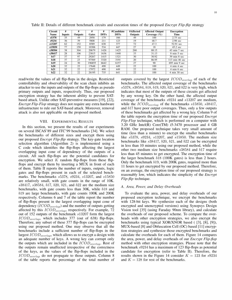
Table II: Details of different benchmark circuits and execution times of the proposed Encrypt Flip-flip strategy
CircuitName
#Inputs
#Outputs
#Gates
#DFFs
#CandidateDFFs
#AffectedOutputs
Affected OutputCoverage (%)
EncryptionTime
s5378 35 49 2958 179 166 49 100 2.75 secs9234 36 39 5808 211 123 19 48.7 2.98 sec
s13207 62 152 8589 638 377 72 47.3 52.91 secs15850 77 150 10306 534 447 27 18 45.2 secs38584 38 304 20679 1426 1425 268 88.15 43 min 7 secs38417 28 106 23815 1636 1448 33 31.13 8 min 5 sec
b17 37 97 29267 1415 1321 30 30.92 39 min 8 secb18 37 23 97569 3320 3191 20 86.95 113 min 46 secb19 24 30 196855 6642 6157 27 90 695 min 9 secb20 32 22 17648 490 449 22 100 4 min 4 secb21 32 22 17972 490 449 22 100 4 min 6 secb22 32 22 26195 735 641 22 100 4 min 30 sec
read/write the values of all flip-flops in the design. Restrictedcontrollability and observability of the scan chain inhibits anattacker to use the inputs and outputs of the flip-flops as pseudoprimary outputs and inputs, respectively. Thus, our proposedencryption strategy has the inherent ability to prevent SAT-based attack. Unlike other SAT-preventive measures [19], [22],Encrypt Flip-Flop strategy does not require any extra hardwareinfrastructure to rule out SAT-based attack. Moreover, removalattack is also not applicable on the proposed method.
VIII. EXPERIMENTAL RESULTS
In this section, we present the results of our experimentson several ISCAS’89 and ITC’99 benchmarks [34]. We selectthe benchmarks of different sizes and encrypt them usingour proposed Encrypt Flip-flip strategy. The key-gate locationselection algorithm (Algorithm 2) is implemented using aC code which identifies the flip-flops affecting the largestoverlapping input cone of dependency of the outputs of acircuit. All such flip-flops are the potential candidates forencryption. We select K random flip-flops from these flip-flops and encrypt them by inserting a MUX in front of eachof them. Table II reports the number of inputs, outputs, logicgates and flip-flops present in each of the selected bench-marks. The benchmarks s5378, s9234, s13207, and s15850are relatively small, with gate counts in the range of 10K.s38417, s38584, b17, b20, b21, and b22 are the medium sizebenchmarks, with gate counts less than 30K, while b18 andb19 are large benchmarks, with gate counts 100K and 200Krespectively. Columns 6 and 7 of the table report the numberof flip-flops present in the largest overlapping input cone ofdependency (ICODoverlap) and the number of outputs gettingaffected by this ICODoverlap, respectively. For example, 72out of 152 outputs of the benchmark s13207 form the largestICODoverlap, which includes 377 (out of 638) flip-flops.Therefore, any subset of these 377 flip-flops can be encryptedusing our proposed method. One may observe that all thebenchmarks include a sufficient number of flip-flops in thelargest ICODoverlap, which allows us to encrypt a design withan adequate number of keys. A wrong key can corrupt onlythe outputs which are included in the ICODoverlap. Rest ofthe outputs remain unaffected irrespective of the correctnessof the keys, as the values of the flip-flops included in theICODoverlap do not propagate to those outputs. Column 8of the table reports the percentage of the total number of
outputs covered by the largest ICODoverlap of each of thebenchmarks. The affected output coverage of the benchmarkss5378, s38584, b18, b19, b20, b21, and b22 is very high, whichindicates that most of the outputs of these circuits get affectedby any wrong key. On the other hand, the affected outputcoverage of the benchmarks s9234 and s13207 are medium,while the ICODoverlap of the benchmarks s15850, s38417,and b17 have poor output coverages. Thus, only a few outputsof these benchmarks get affected by a wrong key. Column 9 ofthe table reports the encryption time of our proposed EncryptFlip-Flop technique, which is performed on a computer with3.20 GHz Intel(R) Core(TM) i5-3470 processor and 4 GBRAM. Our proposed technique takes very small amount oftime (less than a minute) to encrypt the smaller benchmarkslike s5378, s9234, s13207, and s15850. The medium sizebenchmarks like s38417, b20, b21, and b22 can be encryptedin less than 10 minutes using our proposed method, while theother two medium size benchmarks s38584 and b17 requireless than 45 minutes to get encrypted. The encryption time ofthe larger benchmark b18 (100K gates) is less than 2 hours.Only the benchmark b19, with 200K gates, required more than11 hours to get encrypted by our proposed method. Therefore,on an average, the encryption time of our proposed strategy isreasonably low, which indicates the simplicity of the EncryptFlip-flip technique.
A. Area, Power, and Delay Overheads
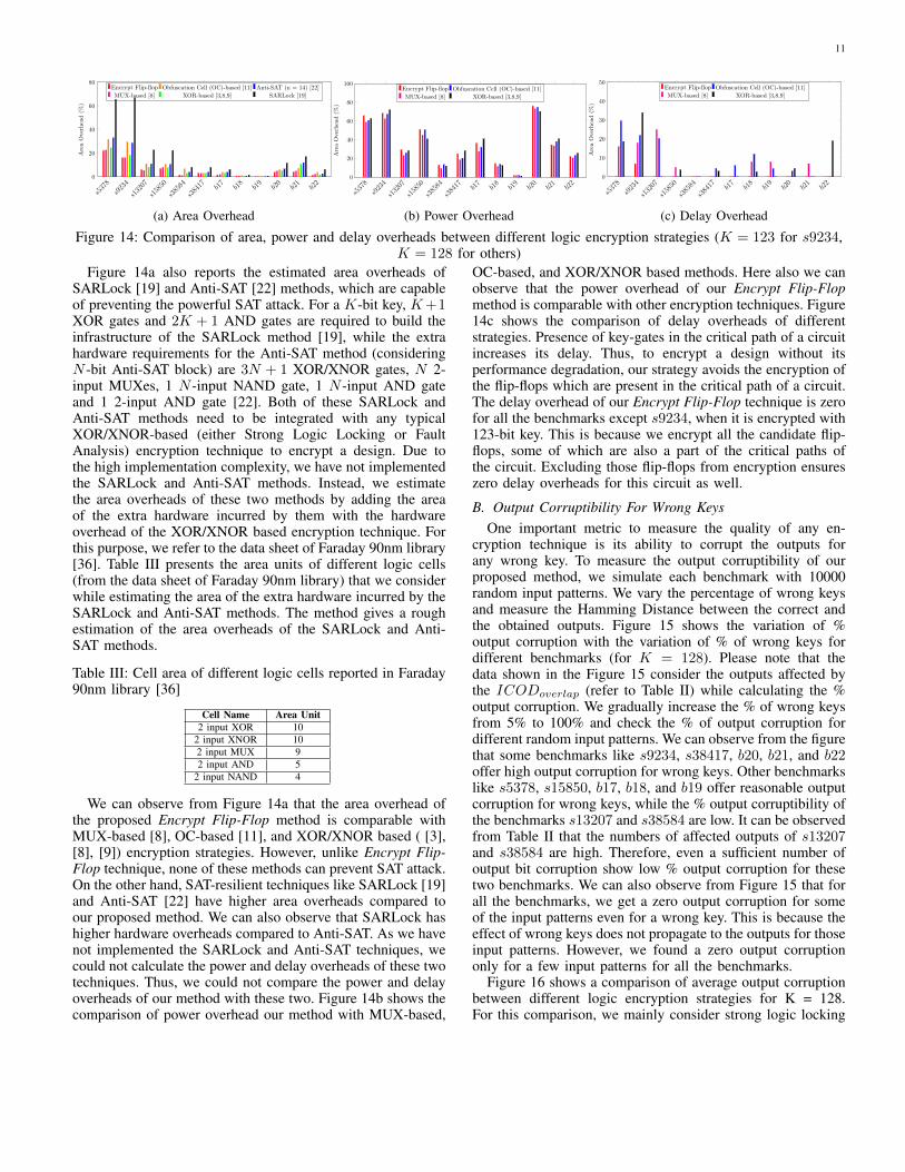
To evaluate the area, power, and delay overheads of ourproposed encryption technique, we encrypt the benchmarkswith 128-bit keys. We synthesize each of the designs (bothencrypted and unencrypted versions) using Synopsys DesignVision tool [35] (using Faraday 90nm library), and calculatethe overheads of our proposed scheme. To compare the over-heads with other encryption strategies, we also encrypt thebenchmarks using typical XOR/XNOR based ( [3], [8], [9]),MUX-based [8] and Obfuscation Cell (OC) based [11] encryp-tion strategies and synthesize those encrypted benchmarks andcalculate the overheads for each of them. Figure 14 comparesthe area, power, and delay overheads of our Encrypt Flip-flopmethod with other encryption strategies. Please note that thebenchmark s9234 has a maximum of 123 flip-flops as potentialcandidate for encryption (refer to Table II). Therefore, theresults shown in the Figure 14 consider K = 123 for s9234and K = 128 for rest of the benchmarks.
11
s5378
s9234
s13207
s15850
s38584
s38417 b1
7b18
b19
b20
b21
b22
0
20
40
60
80A
rea
Over
hea
d(%
)Encrypt Flip-flop Obfuscation Cell (OC)-based [11] Anti-SAT (n = 14) [22]
MUX-based [8] XOR-based [3,8,9] SARLock [19]
(a) Area Overhead
s5378
s9234
s13207
s15850
s38584
s38417 b1
7b18
b19
b20
b21
b22
0
20
40
60
80
100
Are
aO
ver
hea
d(%
)
Encrypt Flip-flop Obfuscation Cell (OC)-based [11]
MUX-based [8] XOR-based [3,8,9]
(b) Power Overhead
s5378
s9234
s13207
s15850
s38584
s38417 b1
7b18
b19
b20
b21
b22
0
10
20
30
40
50
Are
aO
ver
hea
d(%
)
Encrypt Flip-flop Obfuscation Cell (OC)-based [11]
MUX-based [8] XOR-based [3,8,9]
(c) Delay Overhead
Figure 14: Comparison of area, power and delay overheads between different logic encryption strategies (K = 123 for s9234,K = 128 for others)
Figure 14a also reports the estimated area overheads ofSARLock [19] and Anti-SAT [22] methods, which are capableof preventing the powerful SAT attack. For a K-bit key, K+1XOR gates and 2K + 1 AND gates are required to build theinfrastructure of the SARLock method [19], while the extrahardware requirements for the Anti-SAT method (consideringN -bit Anti-SAT block) are 3N + 1 XOR/XNOR gates, N 2-input MUXes, 1 N -input NAND gate, 1 N -input AND gateand 1 2-input AND gate [22]. Both of these SARLock andAnti-SAT methods need to be integrated with any typicalXOR/XNOR-based (either Strong Logic Locking or FaultAnalysis) encryption technique to encrypt a design. Due tothe high implementation complexity, we have not implementedthe SARLock and Anti-SAT methods. Instead, we estimatethe area overheads of these two methods by adding the areaof the extra hardware incurred by them with the hardwareoverhead of the XOR/XNOR based encryption technique. Forthis purpose, we refer to the data sheet of Faraday 90nm library[36]. Table III presents the area units of different logic cells(from the data sheet of Faraday 90nm library) that we considerwhile estimating the area of the extra hardware incurred by theSARLock and Anti-SAT methods. The method gives a roughestimation of the area overheads of the SARLock and Anti-SAT methods.
Table III: Cell area of different logic cells reported in Faraday90nm library [36]
Cell Name Area Unit2 input XOR 10
2 input XNOR 102 input MUX 92 input AND 5
2 input NAND 4
We can observe from Figure 14a that the area overhead ofthe proposed Encrypt Flip-Flop method is comparable withMUX-based [8], OC-based [11], and XOR/XNOR based ( [3],[8], [9]) encryption strategies. However, unlike Encrypt Flip-Flop technique, none of these methods can prevent SAT attack.On the other hand, SAT-resilient techniques like SARLock [19]and Anti-SAT [22] have higher area overheads compared toour proposed method. We can also observe that SARLock hashigher hardware overheads compared to Anti-SAT. As we havenot implemented the SARLock and Anti-SAT techniques, wecould not calculate the power and delay overheads of these twotechniques. Thus, we could not compare the power and delayoverheads of our method with these two. Figure 14b shows thecomparison of power overhead our method with MUX-based,
OC-based, and XOR/XNOR based methods. Here also we canobserve that the power overhead of our Encrypt Flip-Flopmethod is comparable with other encryption techniques. Figure14c shows the comparison of delay overheads of differentstrategies. Presence of key-gates in the critical path of a circuitincreases its delay. Thus, to encrypt a design without itsperformance degradation, our strategy avoids the encryption ofthe flip-flops which are present in the critical path of a circuit.The delay overhead of our Encrypt Flip-Flop technique is zerofor all the benchmarks except s9234, when it is encrypted with123-bit key. This is because we encrypt all the candidate flip-flops, some of which are also a part of the critical paths ofthe circuit. Excluding those flip-flops from encryption ensureszero delay overheads for this circuit as well.
B. Output Corruptibility For Wrong KeysOne important metric to measure the quality of any en-
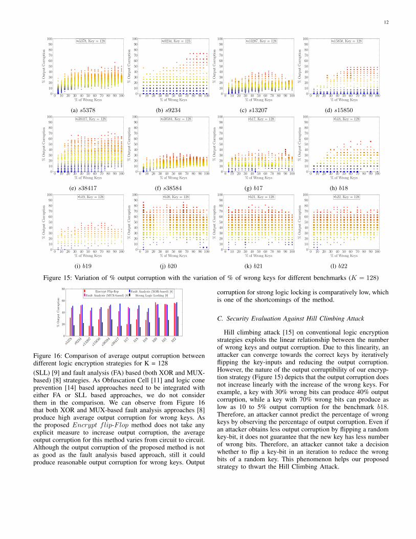
cryption technique is its ability to corrupt the outputs forany wrong key. To measure the output corruptibility of ourproposed method, we simulate each benchmark with 10000random input patterns. We vary the percentage of wrong keysand measure the Hamming Distance between the correct andthe obtained outputs. Figure 15 shows the variation of %output corruption with the variation of % of wrong keys fordifferent benchmarks (for K = 128). Please note that thedata shown in the Figure 15 consider the outputs affected bythe ICODoverlap (refer to Table II) while calculating the %output corruption. We gradually increase the % of wrong keysfrom 5% to 100% and check the % of output corruption fordifferent random input patterns. We can observe from the figurethat some benchmarks like s9234, s38417, b20, b21, and b22offer high output corruption for wrong keys. Other benchmarkslike s5378, s15850, b17, b18, and b19 offer reasonable outputcorruption for wrong keys, while the % output corruptibility ofthe benchmarks s13207 and s38584 are low. It can be observedfrom Table II that the numbers of affected outputs of s13207and s38584 are high. Therefore, even a sufficient number ofoutput bit corruption show low % output corruption for thesetwo benchmarks. We can also observe from Figure 15 that forall the benchmarks, we get a zero output corruption for someof the input patterns even for a wrong key. This is because theeffect of wrong keys does not propagate to the outputs for thoseinput patterns. However, we found a zero output corruptiononly for a few input patterns for all the benchmarks.
Figure 16 shows a comparison of average output corruptionbetween different logic encryption strategies for K = 128.For this comparison, we mainly consider strong logic locking
12
0 10 20 30 40 50 60 70 80 90 1000
10
20
30
40
50
60
70
80
90
100
% of Wrong Keys
%OutputCorruption
s5378, Key = 128
(a) s5378
0 10 20 30 40 50 60 70 80 90 1000
10
20
30
40
50
60
70
80
90
100
% of Wrong Keys
%OutputCorruption
s9234, Key = 123
(b) s9234
0 10 20 30 40 50 60 70 80 90 1000
10
20
30
40
50
60
70
80
90
100
% of Wrong Keys
%OutputCorruption
s13207, Key = 128
(c) s13207
0 10 20 30 40 50 60 70 80 90 1000
10
20
30
40
50
60
70
80
90
100
% of Wrong Keys
%OutputCorruption
s15850, Key = 128
(d) s15850
0 10 20 30 40 50 60 70 80 90 1000
10
20
30
40
50
60
70
80
90
100
% of Wrong Keys
%OutputCorruption
s38417, Key = 128
(e) s38417
0 10 20 30 40 50 60 70 80 90 1000
10
20
30
40
50
60
70
80
90
100
% of Wrong Keys
%OutputCorruption
s38584, Key = 128
(f) s38584
0 10 20 30 40 50 60 70 80 90 1000
10
20
30
40
50
60
70
80
90
100
% of Wrong Keys
%OutputCorruption
b17, Key = 128
(g) b17
0 10 20 30 40 50 60 70 80 90 1000
10
20
30
40
50
60
70
80
90
100
% of Wrong Keys
%OutputCorruption
b18, Key = 128
(h) b18
0 10 20 30 40 50 60 70 80 90 1000
10
20
30
40
50
60
70
80
90
100
% of Wrong Keys
%OutputCorruption
b19, Key = 128
(i) b19
0 10 20 30 40 50 60 70 80 90 1000
10
20
30
40
50
60
70
80
90
100
% of Wrong Keys
%OutputCorruption
b20, Key = 128
(j) b20
0 10 20 30 40 50 60 70 80 90 1000
10
20
30
40
50
60
70
80
90
100
% of Wrong Keys
%OutputCorruption
b21, Key = 128
(k) b21
0 10 20 30 40 50 60 70 80 90 1000
10
20
30
40
50
60
70
80
90
100
% of Wrong Keys
%OutputCorruption
b22, Key = 128
(l) b22
Figure 15: Variation of % output corruption with the variation of % of wrong keys for different benchmarks (K = 128)
s5378
s9234
s13207
s15850
s38584
s38417 b1
7b18
b19
b20
b21
b22
0
20
40
60
80
%O
utp
ut
Cor
rupti
on
Encrypt Flip-flop Fault Analysis (XOR-based) [8]
Fault Analysis (MUX-based) [8] Strong Logic Locking [9]
Figure 16: Comparison of average output corruption betweendifferent logic encryption strategies for K = 128(SLL) [9] and fault analysis (FA) based (both XOR and MUX-based) [8] strategies. As Obfuscation Cell [11] and logic coneprevention [14] based approaches need to be integrated witheither FA or SLL based approaches, we do not considerthem in the comparison. We can observe from Figure 16that both XOR and MUX-based fault analysis approaches [8]produce high average output corruption for wrong keys. Asthe proposed Encrypt flip-Flop method does not take anyexplicit measure to increase output corruption, the averageoutput corruption for this method varies from circuit to circuit.Although the output corruption of the proposed method is notas good as the fault analysis based approach, still it couldproduce reasonable output corruption for wrong keys. Output
corruption for strong logic locking is comparatively low, whichis one of the shortcomings of the method.
C. Security Evaluation Against Hill Climbing Attack
Hill climbing attack [15] on conventional logic encryptionstrategies exploits the linear relationship between the numberof wrong keys and output corruption. Due to this linearity, anattacker can converge towards the correct keys by iterativelyflipping the key-inputs and reducing the output corruption.However, the nature of the output corruptibility of our encryp-tion strategy (Figure 15) depicts that the output corruption doesnot increase linearly with the increase of the wrong keys. Forexample, a key with 30% wrong bits can produce 40% outputcorruption, while a key with 70% wrong bits can produce aslow as 10 to 5% output corruption for the benchmark b18.Therefore, an attacker cannot predict the percentage of wrongkeys by observing the percentage of output corruption. Even ifan attacker obtains less output corruption by flipping a randomkey-bit, it does not guarantee that the new key has less numberof wrong bits. Therefore, an attacker cannot take a decisionwhether to flip a key-bit in an iteration to reduce the wrongbits of a random key. This phenomenon helps our proposedstrategy to thwart the Hill Climbing Attack.
13
Table IV: A comparative study between different logic encryption strategies
EncryptionTechnique
Resilience Against Different Attacks OutputCorruptability
Hardwareoverhead
(K-bit key)
Encryptiontime
ImplementationComplexityPath
Sensitization [9]Logic
Cone [14]Hill
Climbing [15] SAT [16] ScanBased
Random [3] × × × × × Low K XOR/(XNOR + NOT) Very Fast Very Simple
Fault Analysis (FA)(XOR-based) [8] × × × × × High K XOR/
(XNOR + NOT) Slow Medium
Fault Analysis(MUX-based) [8] × × × × × High K MUX Slow Medium
Strong LogicLocking (SLL) [9] × × × Low K XOR/
(XNOR + NOT) Slow High
ObfuscationCell (OC) [11] × × × × × Low K MUX +
K NOT Very Fast Very Simple
Logic ConePrevention [14] × × × × Low K (MUX +
XOR/XNOR) Medium Medium
ExternalKey-Dependency [6] × × High 4K XOR/
(XNOR+NOT) Slow High
SLL+SARLock [19] × × Low 2K + 1 XORs +2K + 1 ANDs Slow Very High
Anti-SAT + FA [22] × × × × Medium
K + 3N + 1 XOR/XNOR +N 2-input MUX +
1 N-input (NAND + AND)+ 1 2-input AND
Slow Very High
Encrypt Flip-Flop Varies from circuitto circuit K MUX + 1 XOR + 2 AND + 1 OR + 1 DFF Fast Medium
IX. DISCUSSION
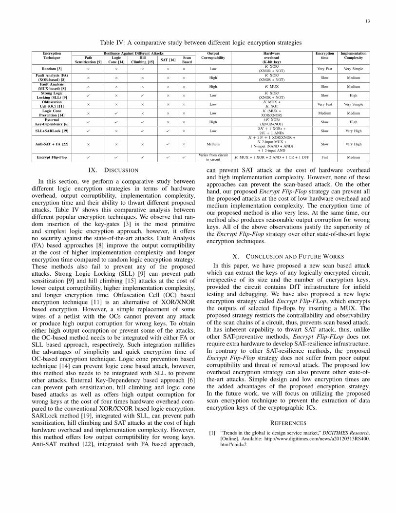
In this section, we perform a comparative study betweendifferent logic encryption strategies in terms of hardwareoverhead, output corruptibility, implementation complexity,encryption time and their ability to thwart different proposedattacks. Table IV shows this comparative analysis betweendifferent popular encryption techniques. We observe that ran-dom insertion of the key-gates [3] is the most primitiveand simplest logic encryption approach, however, it offersno security against the state-of-the-art attacks. Fault Analysis(FA) based approaches [8] improve the output corruptibilityat the cost of higher implementation complexity and longerencryption time compared to random logic encryption strategy.These methods also fail to prevent any of the proposedattacks. Strong Logic Locking (SLL) [9] can prevent pathsensitization [9] and hill climbing [15] attacks at the cost oflower output corruptibility, higher implementation complexity,and longer encryption time. Obfuscation Cell (OC) basedencryption technique [11] is an alternative of XOR/XNORbased encryption. However, a simple replacement of somewires of a netlist with the OCs cannot prevent any attackor produce high output corruption for wrong keys. To obtaineither high output corruption or prevent some of the attacks,the OC-based method needs to be integrated with either FA orSLL based approach, respectively. Such integration nullifiesthe advantages of simplicity and quick encryption time ofOC-based encryption technique. Logic cone prevention basedtechnique [14] can prevent logic cone based attack, however,this method also needs to be integrated with SLL to preventother attacks. External Key-Dependency based approach [6]can prevent path sensitization, hill climbing and logic conebased attacks as well as offers high output corruption forwrong keys at the cost of four times hardware overhead com-pared to the conventional XOR/XNOR based logic encryption.SARLock method [19], integrated with SLL, can prevent pathsensitization, hill climbing and SAT attacks at the cost of highhardware overhead and implementation complexity. However,this method offers low output corruptibility for wrong keys.Anti-SAT method [22], integrated with FA based approach,
can prevent SAT attack at the cost of hardware overheadand high implementation complexity. However, none of theseapproaches can prevent the scan-based attack. On the otherhand, our proposed Encrypt Flip-Flop strategy can prevent allthe proposed attacks at the cost of low hardware overhead andmedium implementation complexity. The encryption time ofour proposed method is also very less. At the same time, ourmethod also produces reasonable output corruption for wrongkeys. All of the above observations justify the superiority ofthe Encrypt Flip-Flop strategy over other state-of-the-art logicencryption techniques.
X. CONCLUSION AND FUTURE WORKS
In this paper, we have proposed a new scan based attackwhich can extract the keys of any logically encrypted circuit,irrespective of its size and the number of encryption keys,provided the circuit contains DfT infrastructure for infieldtesting and debugging. We have also proposed a new logicencryption strategy called Encrypt Flip-FLop, which encryptsthe outputs of selected flip-flops by inserting a MUX. Theproposed strategy restricts the contrallability and observabilityof the scan chains of a circuit, thus, prevents scan based attack.It has inherent capability to thwart SAT attack, thus, unlikeother SAT-preventive methods, Encrypt Flip-FLop does notrequire extra hardware to develop SAT-resilience infrastructure.In contrary to other SAT-resilience methods, the proposedEncrypt Flip-Flop strategy does not suffer from poor outputcorruptibility and threat of removal attack. The proposed lowoverhead encryption strategy can also prevent other state-of-the-art attacks. Simple design and low encryption times arethe added advantages of the proposed encryption strategy.In the future work, we will focus on utilizing the proposedscan encryption technique to prevent the extraction of dataencryption keys of the cryptographic ICs.
REFERENCES
[1] “Trends in the global ic design service market,” DIGITIMES Research.[Online]. Available: http://www.digitimes.com/news/a20120313RS400.html?chid=2
14
[2] M. Rostami, F. Koushanfar, and R. Karri, “A primer on hardwaresecurity: Models, methods, and metrics,” Proceedings of the IEEE, vol.102, no. 8, pp. 1283–1295, 2014.
[3] J. A. Roy, F. Koushanfar, and I. L. Markov, “Epic: Ending piracy ofintegrated circuits,” in DATE, 2008, pp. 1069–1074.
[4] “Innovation is at risk: Losses of up to $4 billion annually dueto ip infringement,” SEMI. [Online]. Available: http://semi.org/en/innovation-risk-losses-4-billion-annually-due-ip-infringement
[5] M. Yasin, S. M. Saeed, J. Rajendran, and O. Sinanoglu, “Activationof logic encrypted chips: Pre-test or post-test?” in Proceedings of the2016 Conference on Design, Automation & Test in Europe. EDAConsortium, 2016, pp. 139–144.
[6] R. Karmakar, N. Prasad, S. Chattopadhyay, R. Kapur, and I. Sengupta,“A new logic encryption strategy ensuring key interdependency,” inVLSID. IEEE, 2017, pp. 429–434.
[7] R. S. Chakraborty and S. Bhunia, “Harpoon: an obfuscation-based socdesign methodology for hardware protection,” IEEE Tran. on CAD ofIntegrated Circuits and Systems, vol. 28, no. 10, pp. 1493–1502, 2009.
[8] J. Rajendran, H. Zhang, C. Zhang, G. S. Rose, Y. Pino, O. Sinanoglu,and R. Karri, “Fault analysis-based logic encryption,” IEEE Tran. onComputers, vol. 64, no. 2, pp. 410–424, 2015.
[9] M. Yasin, J. Rajendran, O. Sinanoglu, and R. Karri, “On improving thesecurity of logic locking,” IEEE Tran. on Computer-Aided Design ofIntegrated Circuits and Systems, no. 99, pp. 1–1, 2015.
[10] S. Dupuis, P.-S. Ba, G. Di Natale, M.-L. Flottes, and B. Rouzeyre,“A novel hardware logic encryption technique for thwarting illegaloverproduction and hardware trojans,” in (IOLTS), 2014, pp. 49–54.
[11] J. Zhang, “A practical logic obfuscation technique for hardware se-curity,” IEEE Tran. on Very Large Scale Integration (VLSI) Systems,vol. 24, no. 3, pp. 1193–1197, 2016.
[12] A. Baumgarten, A. Tyagi, and J. Zambreno, “Preventing ic piracyusing reconfigurable logic barriers,” IEEE Design & Test of Computers,vol. 27, no. 1, 2010.
[13] X. Wang, X. Jia, Q. Zhou, Y. Cai, J. Yang, M. Gao, and G. Qu, “Secureand low-overhead circuit obfuscation technique with multiplexers,” inGLSVLSI. IEEE, 2016, pp. 133–136.
[14] Y.-W. Lee and N. A. Touba, “Improving logic obfuscation via logiccone analysis,” in (LATS). IEEE, 2015, pp. 1–6.
[15] S. M. Plaza and I. L. Markov, “Solving the third-shift problem in icpiracy with test-aware logic locking,” IEEE Tran. on CAD of IntegratedCircuits and Systems, vol. 34, no. 6, pp. 961–971, 2015.
[16] P. Subramanyan, S. Ray, and S. Malik, “Evaluating the security of logicencryption algorithms,” in HOST, 2015, pp. 137–143.
[17] R. Karmakar, S. Chattopadhyay, and R. Kapur, “Enhancing securityof logic encryption using embedded key generation unit,” in ITC-Asia.IEEE, 2017.
[18] K. Shamsi, M. Li, T. Meade, Z. Zhao, D. Z. Pan, and Y. Jin, “Appsat:Approximately deobfuscating integrated circuits,” in HOST. IEEE,2017, pp. 95–100.
[19] M. Yasin, B. Mazumdar, J. J. Rajendran, and O. Sinanoglu, “Sarlock:Sat attack resistant logic locking,” in HOST. IEEE, 2016, pp. 236–241.
[20] M. Yasin, A. Sengupta, B. C. Schafer, Y. Makris, O. Sinanoglu, andJ. J. Rajendran, “What to lock?: Functional and parametric locking,” inGLSVLSI. ACM, 2017, pp. 351–356.
[21] Y. Shen and H. Zhou, “Double dip: Re-evaluating security of logicencryption algorithms,” in GLSVLSI. ACM, 2017, pp. 179–184.
[22] Y. Xie and A. Srivastava, “Mitigating sat attack on logic locking,” IACRCryptology ePrint Archive, vol. 2016(590), 2016.
[23] M. Yasin, B. Mazumdar, O. Sinanoglu, and J. Rajendran, “Securityanalysis of anti-sat,” IACR Cryptology ePrint Archive, vol. 2016(896).
[24] X. Xu, B. Shakya, M. M. Tehranipoor, and D. Forte, “Novel bypassattack and bdd-based tradeoff analysis against all known logic lockingattacks,” IACR Cryptology ePrint Archive, 2017.
[25] Y. Xie and A. Srivastava, “Delay locking: Security enhancement of logiclocking against ic counterfeiting and overproduction,” in DAC. ACM,2017, p. 9.
[26] U. Guin, Z. Zhou, and A. Singh, “A novel design-for-security (dfs)architecture to prevent unauthorized ic overproduction,” in VTS. IEEE,2017, pp. 1–6.
[27] K. Shamsi, M. Li, T. Meade, Z. Zhao, D. Z. Pan, and Y. Jin, “Cyclicobfuscation for creating sat-unresolvable circuits,” in GLSVLSI. ACM,2017, pp. 173–178.
[28] H. Zhou, R. Jiang, and S. Kong, “Cycsat: Sat-based attack on cycliclogic encryptions,” IACR Cryptology ePrint Archive, vol. 2017(626).
[29] K. Juretus and I. Savidis, “Reduced overhead gate level logic encryp-tion,” in GLSVLSI. IEEE, 2016, pp. 15–20.
[30] Y. Bi, X. S. Hu, Y. Jin, M. Niemier, K. Shamsi, and X. Yin, “Enhancinghardware security with emerging transistor technologies,” in GLSVLSI.IEEE, 2016, pp. 305–310.
[31] X. Chen, Q. Liu, Y. Wang, Q. Xu, and H. Yang, “Low-overheadimplementation of logic encryption using gate replacement techniques,”in ISQED. IEEE, 2017, pp. 257–263.
[32] A. Cui, G. Qu, and Y. Zhang, “Ultra-low overhead dynamic watermark-ing on scan design for hard ip protection,” IEEE Tran. on InformationForensics and Security, vol. 10, no. 11, pp. 2298–2313, 2015.
[33] J. Ye, Y. Huang, Y. Hu, W.-T. Cheng, R. Guo, L. Lai, T.-P. Tai, X. Li,W. Changchien, D.-M. Lee et al., “Diagnosis and layout aware (dla)scan chain stitching,” IEEE Tran. on Very Large Scale Integration(VLSI) Systems, vol. 23, no. 3, pp. 466–479, 2015.
[34] C. Albrecht, “Iwls 2005 benchmarks,” in International Workshop forLogic Synthesis (IWLS): http://www. iwls. org, 2005.
[35] Design Vision ”User Guide”, Version 2002.05, Synopsys Inc.[36] [Online]. Available: www.cl.cam.ac.uk/research/srg/han/ACS-P35/
documents/90nm-cell.pdf
Rajit Karmakar received his MS degree in Micro-electronics and VLSI from Indian Institute of Tech-nology, Kharagpur, India, in 2015. He is presentlya PhD student in the Department of Electronicsand Electrical Communication Engineering, IndianInstitute of Technology, Kharagpur, India. His cur-rent research interests include hardware security andVLSI Testing. He is a student member of IEEE.
Santanu Chattopadhyay received the B.E. degree incomputer science and technology from Calcutta Uni-versity, Kolkata, India, in 1990, the M.Tech. degreein computer and information technology and the PhDdegree in computer science and engineering from theIIT Kharagpur, Kharagpur, India, in 1992 and 1996,respectively. He is a Professor with the Departmentof Electronics and Electrical Communication Engi-neering at IIT Kharagpur. He has published morethan 150 technical papers in peer-reviewed journalsand conferences. His current research interests in-
clude digital circuit design, testing and diagnosis, network-on-chip design andtest, and low-power circuit design and test. He is a senior member of IEEE.
Rohit Kapur is a Fellow in Synopsys. A recognizedauthorith in Test, he holds 25 patents and over ahundred publications. Rohit has made contributionto leading Synopsys products including DFTMAX,DFTMAX Ultra, and TetraMAX. He received hisPhD in Computer Engineering from the Universityof Texas in 1992. He is a IEEE Fellow and TTTC2nd Vice Chair. He was the group chair for the IEEECore Test Language (CTL) standard. He is also inthe editorial board of the Computer Magazine.