Embed Size (px)
Citation preview
1
Accelerator Physics Accelerator Physics Aspects Aspects LHCbLHCb
[email protected] CERN SL/AP
Layout Crossing Scheme Luminosity Collision Scheme Electron Cloud Impedances Official Schedule
2
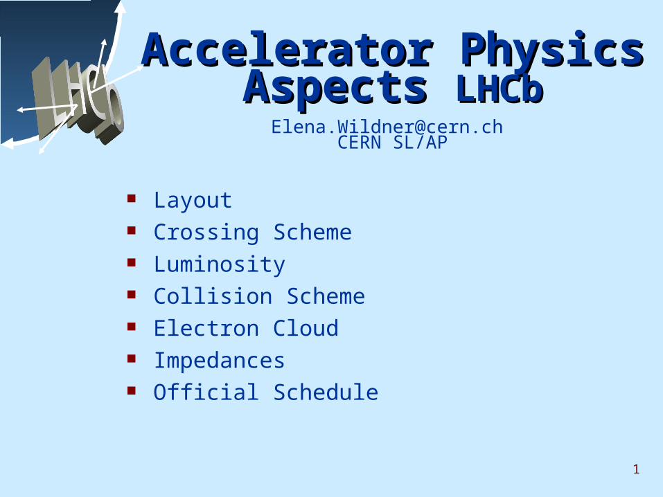
Layout of the LHCLayout of the LHC
3
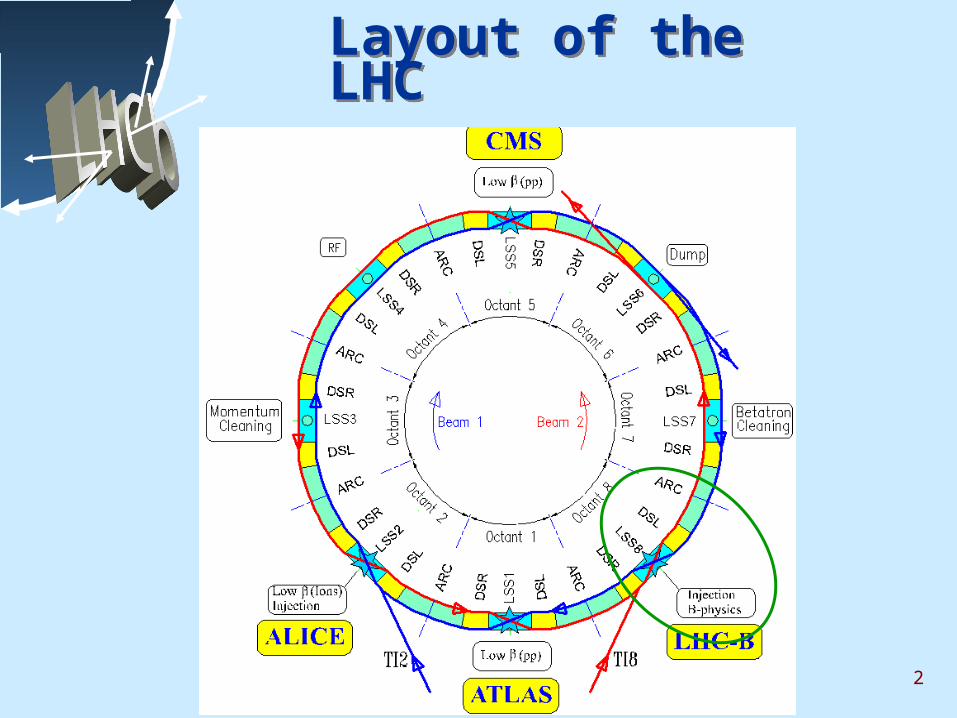
Layout of IR8Layout of IR8
Dispersion Suppressor TripletMatching
4
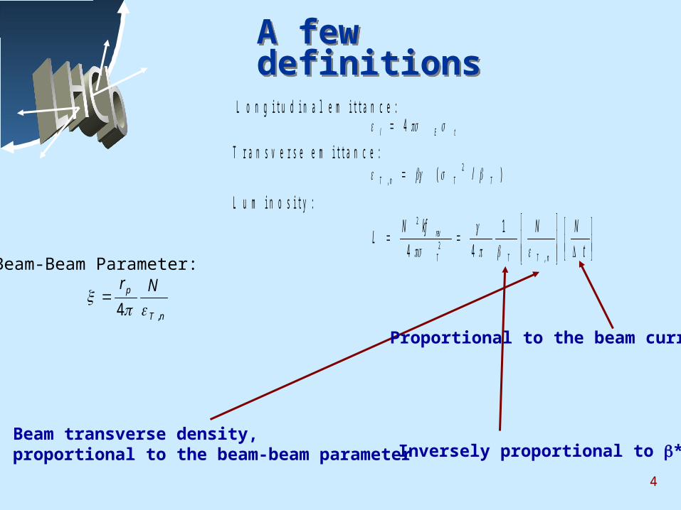
A few definitions A few definitions L o n g i t u d i n a l e m i t t a n c e :
tEl 4T r a n s v e r s e e m i t t a n c e :
)/( 2, TTnT
L u m i n o s i t y :
t
NNkfNL
nTTT
rev
,2
2 1
44
Beam transverse density,proportional to the beam-beam parameter
Proportional to the beam current
nT
p Nr
,4
Inversely proportional to *
Beam-Beam Parameter:
5
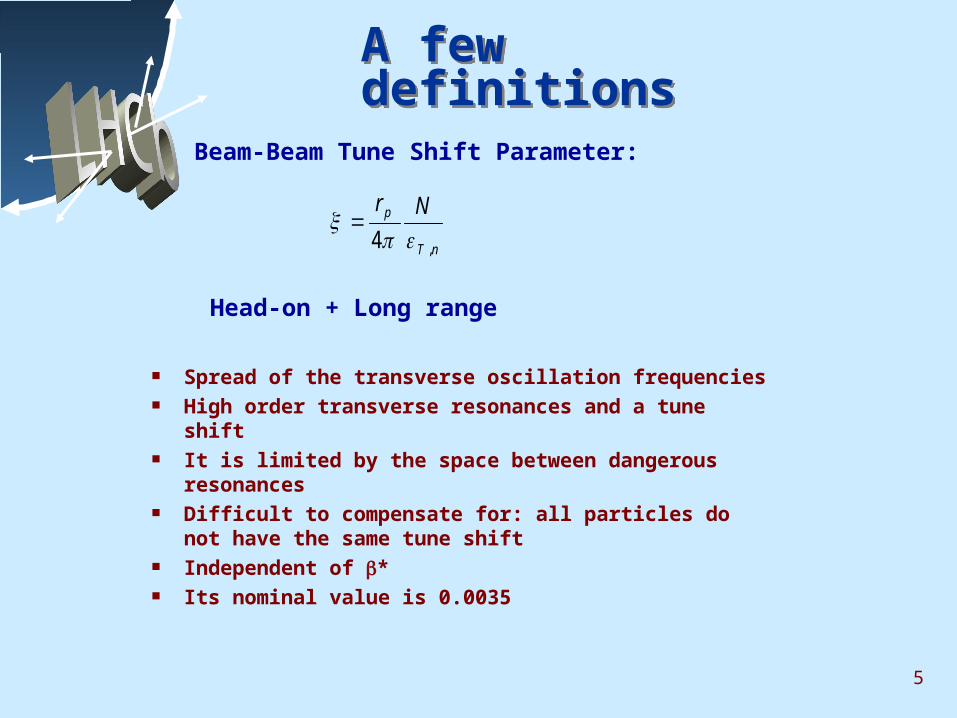
A few definitions A few definitions
Head-on + Long range
nT
p Nr
,4
Beam-Beam Tune Shift Parameter:
Spread of the transverse oscillation frequencies High order transverse resonances and a tune shift It is limited by the space between dangerous
resonances Difficult to compensate for: all particles do not
have the same tune shift Independent of * Its nominal value is 0.0035
6
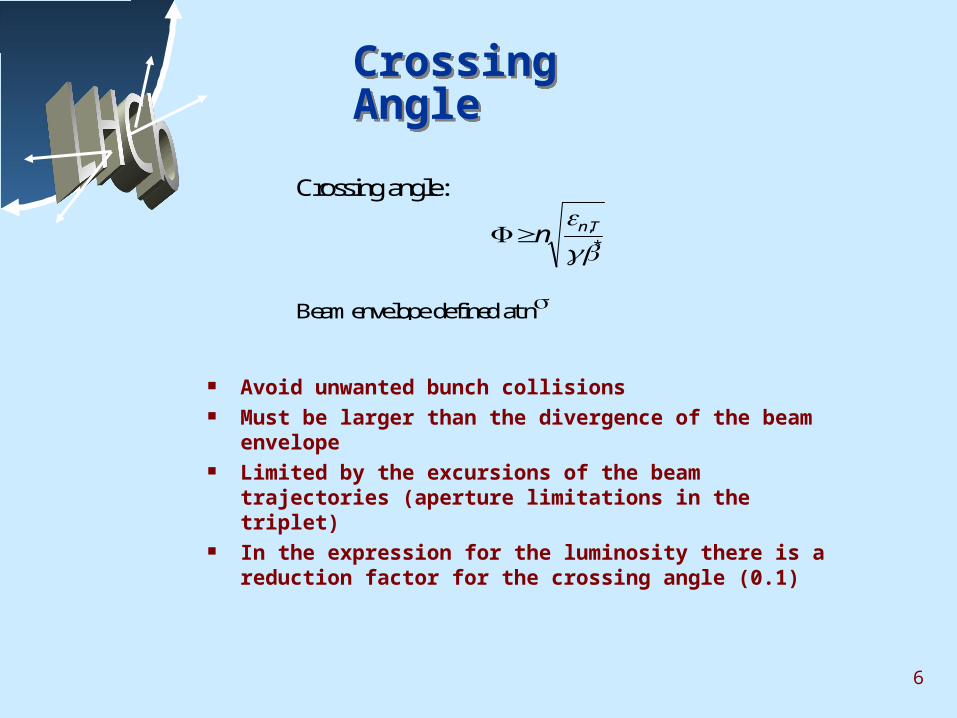
Crossing Angle Crossing Angle
Crossing angle:
*,
Tnn
Beam envelope defined at n
Avoid unwanted bunch collisions Must be larger than the divergence of the beam
envelope Limited by the excursions of the beam trajectories
(aperture limitations in the triplet) In the expression for the luminosity there is a
reduction factor for the crossing angle (0.1)
7
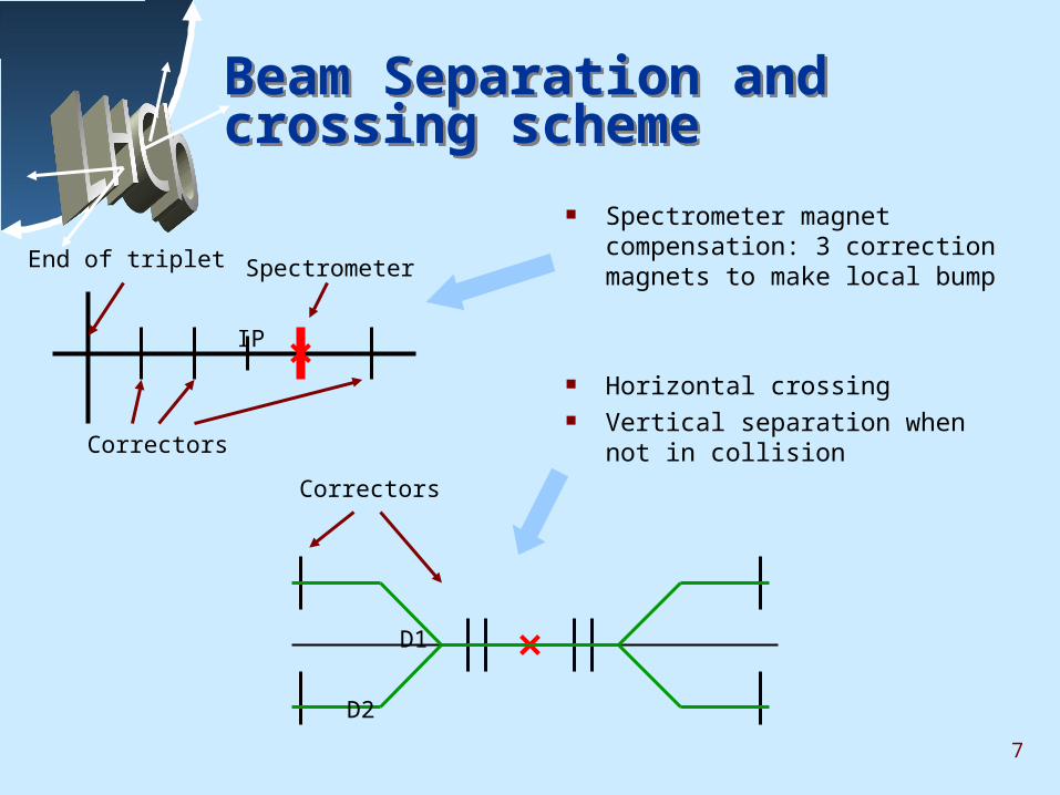
Beam Separation and crossing scheme Beam Separation and crossing scheme
Spectrometer magnet compensation: 3 correction magnets to make local bump
Horizontal crossing Vertical separation when not in
collision
Spectrometer
Correctors
End of triplet
Correctors
D2
D1
IP
8
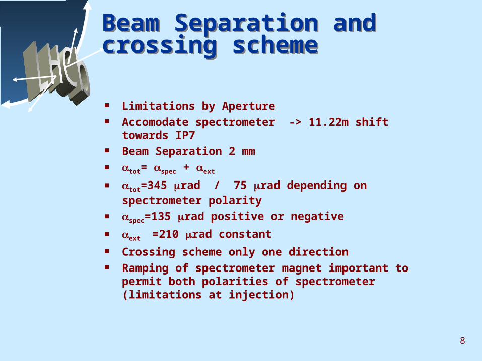
Beam Separation and crossing scheme Beam Separation and crossing scheme
Limitations by Aperture Accomodate spectrometer -> 11.22m shift towards
IP7 Beam Separation 2 mm tot= spec + ext
tot=345 rad / 75 rad depending on spectrometer polarity
spec=135 rad positive or negative
ext =210 rad constant Crossing scheme only one direction Ramping of spectrometer magnet important to permit
both polarities of spectrometer (limitations at injection)
9
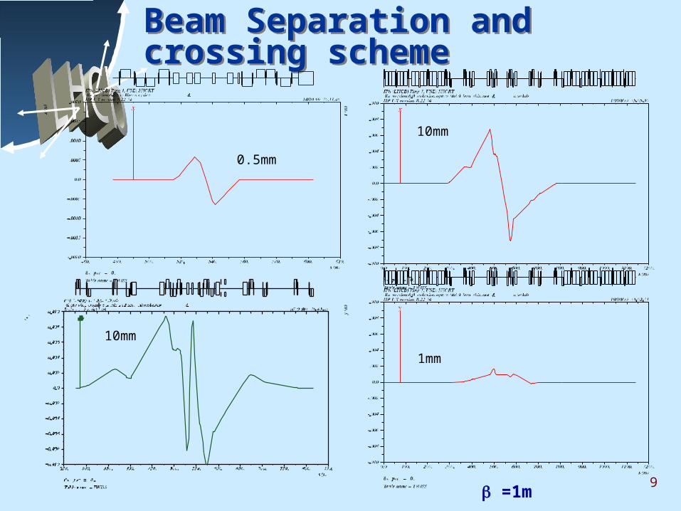
Beam Separation and crossing scheme Beam Separation and crossing scheme
=1m
10mm
10mm
1mm
0.5mm
10
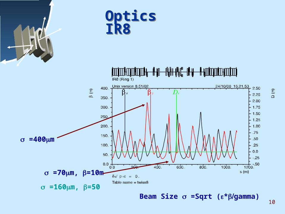
Optics IR8 Optics IR8
Beam Size =Sqrt (*gamma)
=70m, =10m
=400m
=160m, =50
11
10 20 30 40 50
73
74
75
76
77
78
Nominal
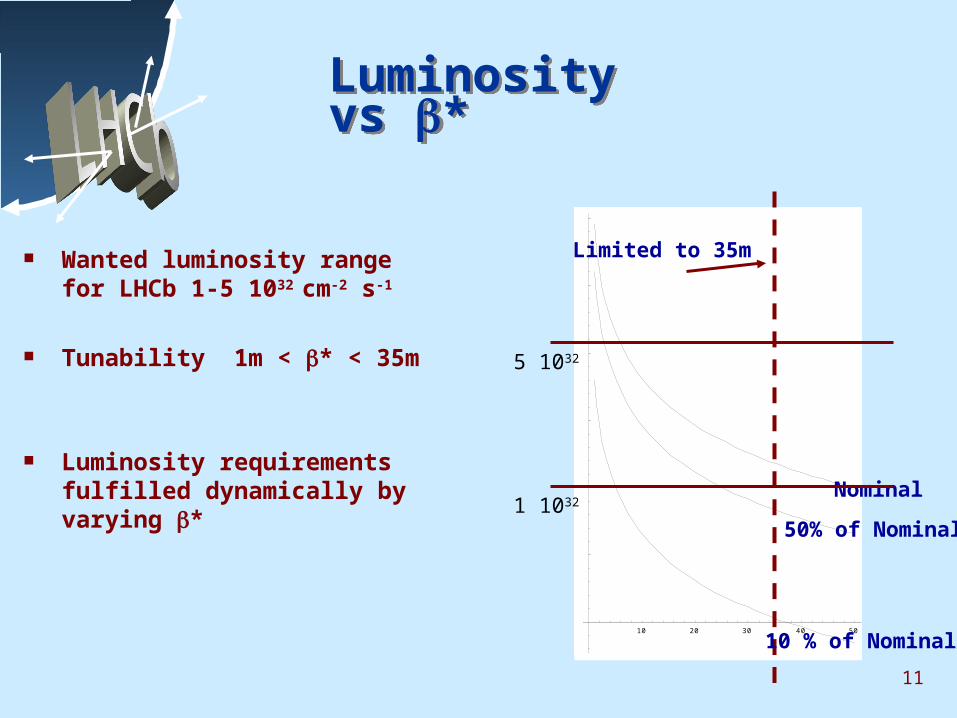
Luminosity vs *Luminosity vs *
Wanted luminosity range for LHCb 1-5 1032 cm-2 s-1
Tunability 1m < * < 35m
Luminosity requirements fulfilled dynamically by varying *
Limited to 35m
5 1032
1 1032
50% of Nominal
10 % of Nominal
12
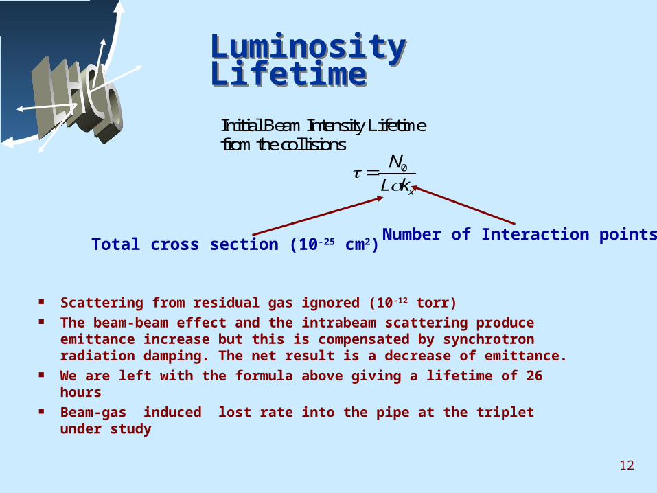
Luminosity LifetimeLuminosity Lifetime
Scattering from residual gas ignored (10-12 torr) The beam-beam effect and the intrabeam scattering produce
emittance increase but this is compensated by synchrotron radiation damping. The net result is a decrease of emittance.
We are left with the formula above giving a lifetime of 26 hours Beam-gas induced lost rate into the pipe at the triplet under
study
Initial Beam Intensity Lifetimefrom the collisions
xkL
N
0
Number of Interaction pointsTotal cross section (10-25 cm2)
13
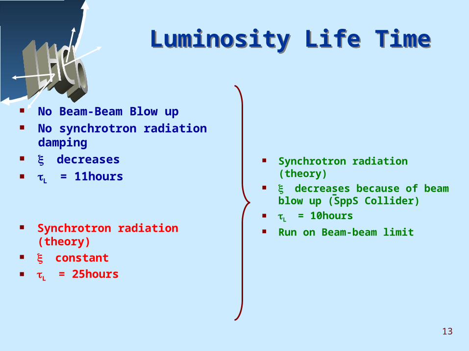
Luminosity Life TimeLuminosity Life Time
No Beam-Beam Blow up No synchrotron radiation damping decreases L = 11hours
Synchrotron radiation (theory) constant L = 25hours
Synchrotron radiation (theory) decreases because of beam
blow up (SppS Collider) L = 10hours Run on Beam-beam limit
14
Collision schemeCollision scheme
Distance between IPs = 891 half buckets: collision scheme has to repeat from one IP to the other
“Holes” (empty buckets) due to injection kickers SPS and LHC, dump Kicker LHC
There are 2808 filled buckets out of 3564 according to following scheme: {[(72b+8e)*3+30e]*2+[(72b+8e)*4+31e]}*3{[(72b+8e)*3+30e]*3+81e}
“Pacman” bunches: do not encounter bunches of the other beam in one or several parasitic collision points
“Superpacman” bunches: as “pacman” but not even at the collision point
15
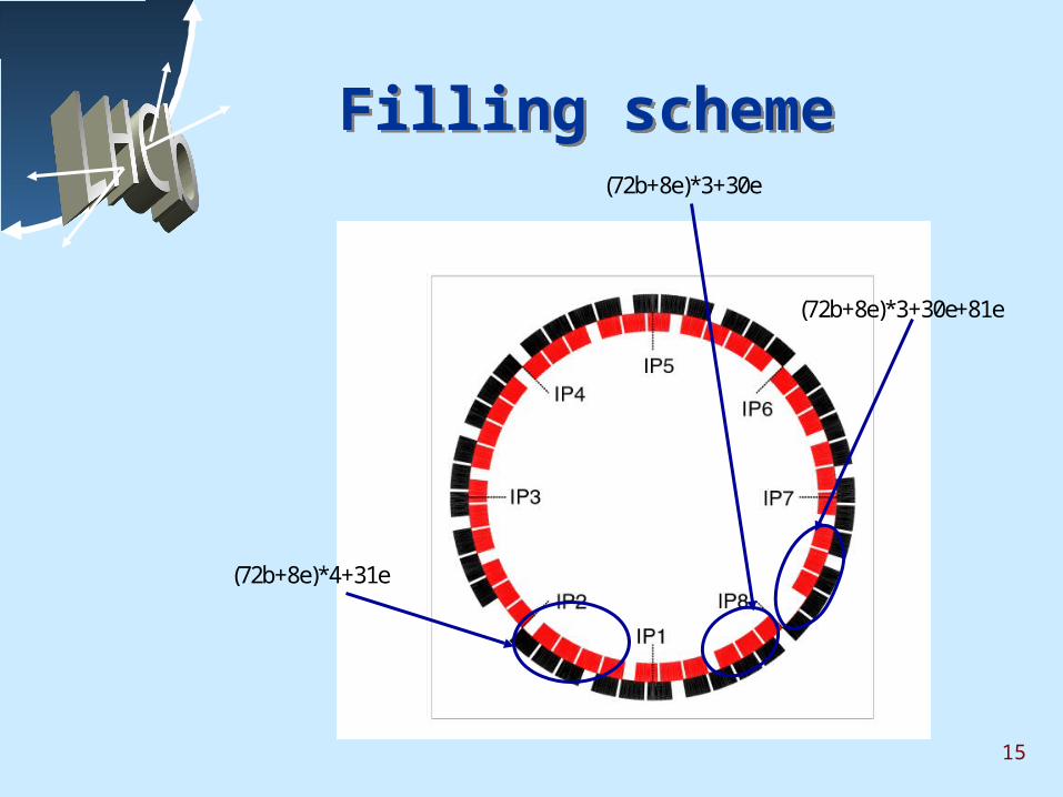
Filling schemeFilling scheme
(72b+8e)*3+30e+81e
(72b+8e)*3+30e
(72b+8e)*4+31e
16
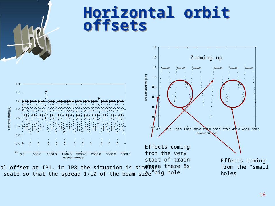
Horizontal orbit offsetsHorizontal orbit offsets
Horizontal offset at IP1, in IP8 the situation is similar, need to scale so that the spread 1/10 of the beam size
Zooming up
Effects coming from the very start of train where there is a “big hole”
Effects coming from the “small holes”
17
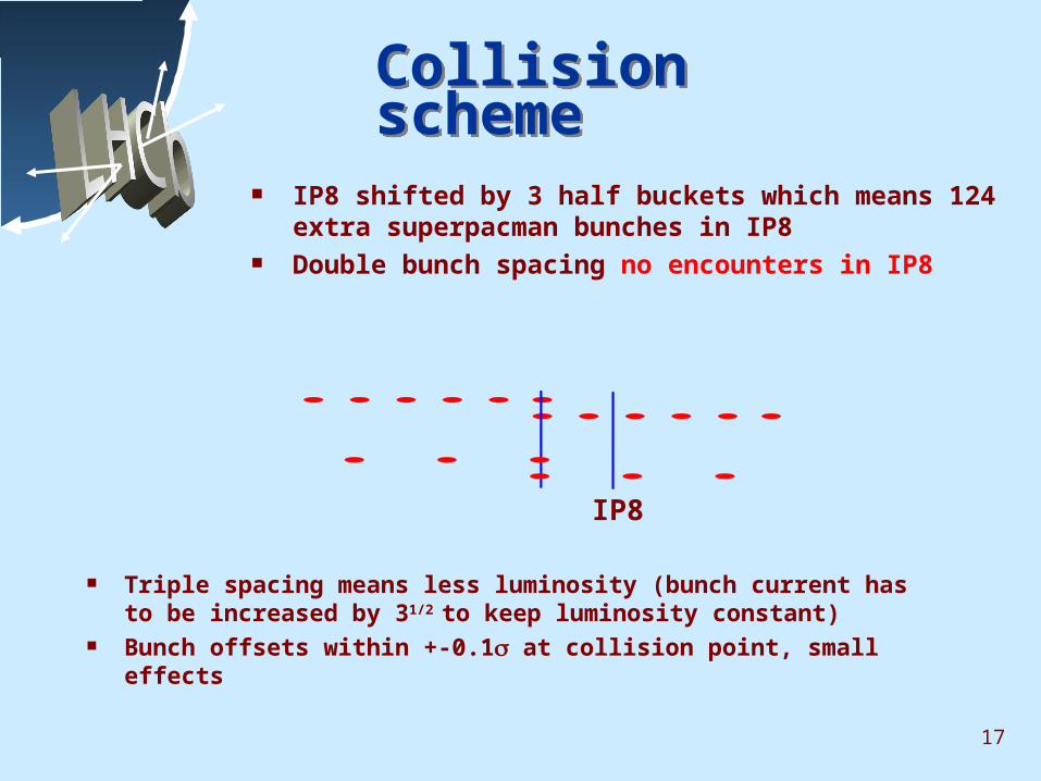
Collision schemeCollision scheme
IP8 shifted by 3 half buckets which means 124 extra superpacman bunches in IP8
Double bunch spacing no encounters in IP8
Triple spacing means less luminosity (bunch current has to be increased by 31/2 to keep luminosity constant)
Bunch offsets within +-0.1 at collision point, small effects
IP8
18
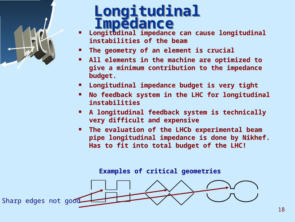
Longitudinal ImpedanceLongitudinal Impedance Longitudinal impedance can cause longitudinal
instabilities of the beam The geometry of an element is crucial All elements in the machine are optimized to give a
minimum contribution to the impedance budget. Longitudinal impedance budget is very tight No feedback system in the LHC for longitudinal
instabilities A longitudinal feedback system is technically very
difficult and expensive The evaluation of the LHCb experimental beam pipe
longitudinal impedance is done by Nikhef. Has to fit into total budget of the LHC!
Examples of critical geometries
Sharp edges not good
19
Transverse ImpedanceTransverse Impedance
A transverse feedback system is required in the LHC to cure the effect of transverse impedance (resistive wall instability).
Aluminum, copper and beryllium are good materials (stainless steel not so good).
Transverse impedance should not exceed budget because of emittance conservation (feedback capabilities are limited)
20
Higher Order ModesHigher Order Modes
Depends on the geometry of the object Frequencey spectrum of loss factor should not
overlap, bunch spectrum Different positioning of the vertex detector gives
different resonance conditions All positions of the detector have to be evaluated Heating up change resonance conditions, cooling
down etc. Pumping effect.
Different situations should be carefully evaluated
21
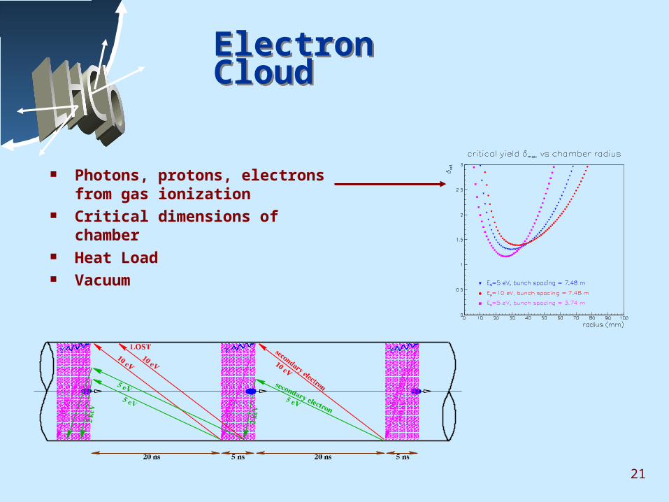
Electron Cloud Electron Cloud
Photons, protons, electrons from gas ionization
Critical dimensions of chamber Heat Load Vacuum
22
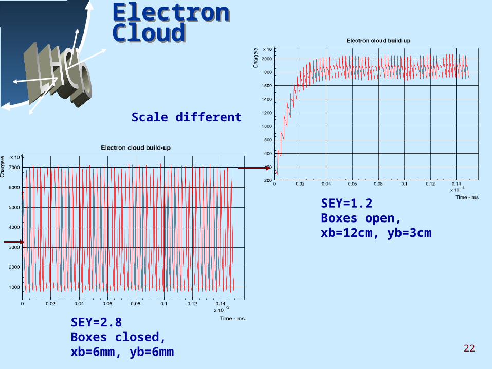
Electron Cloud Electron Cloud
Scale different
SEY=1.2Boxes open, xb=12cm, yb=3cm
SEY=2.8Boxes closed, xb=6mm, yb=6mm
23
Official Schedule Official Schedule
First Beam 01/02/2006
First Collisions 01/04/2006 L *=0.5=5 1032cm -2 s-1
Shut Down 01/05-31/07/2006
Physics Run 01/08/2006-28/02/2007 L *=0.5>= 2 1033cm -2 s-1
24
People who Contributed People who Contributed
Optics: Oliver Brüning Crossing Scheme: Werner Herr, Oliver Brüning Electron Cloud: Frank Zimmermann, Oliver Brüning Impedance: Daniel Brandt, Oliver Brüning Lattice files: Elena Wildner Aperture: Bernard Jeanneret Beam-Beam: H.Grote
25
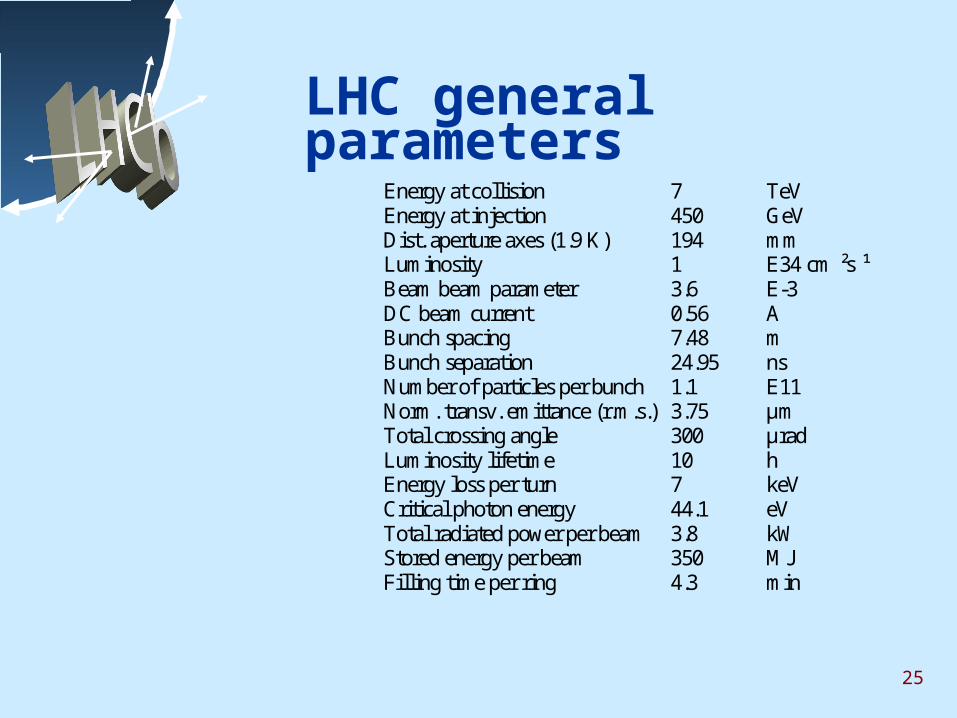
LHC general parameters Energy at collision 7 TeV Energy at injection 450 GeV
Dist. aperture axes (1.9 K) 194 mm Luminosity 1 E34 cm ²s ¹ Beam beam parameter 3.6 E-3 DC beam current 0.56 A Bunch spacing 7.48 m Bunch separation 24.95 ns Number of particles per bunch 1.1 E11 Norm. transv. emittance (r.m.s.) 3.75 µm Total crossing angle 300 µrad
Luminosity lifetime 10 hEnergy loss per turn 7 keVCritical photon energy 44.1 eV
Total radiated power per beam 3.8 kW Stored energy per beam 350 MJ
Filling time per ring 4.3 min
26
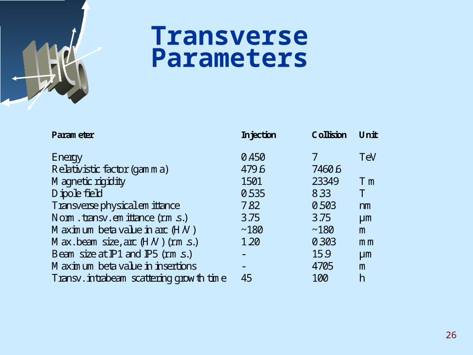
Transverse Parameters
Parameter Injection Collision Unit
Energy 0.450 7 TeVRelativistic factor (gamma) 479.6 7460.6Magnetic rigidity 1501 23349 T mDipole field 0.535 8.33 TTransverse physical emittance 7.82 0.503 nmNorm. transv. emittance (r.m.s.) 3.75 3.75 µmMaximum beta value in arc (H/V) ~180 ~180 mMax. beam size, arc (H/V) (r.m.s.) 1.20 0.303 mmBeam size at IP1 and IP5 (r.m.s.) - 15.9 µmMaximum beta value in insertions - 4705 mTransv. intrabeam scattering growth time 45 100 h
27
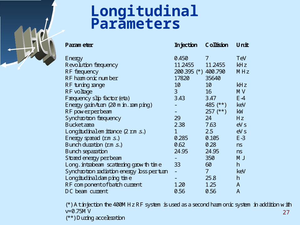
Longitudinal Parameters
Parameter Injection Collision Unit
Energy 0.450 7 TeVRevolution frequency 11.2455 11.2455 kHzRF frequency 200.395 (*) 400.790 MHzRF harmonic number 17820 35640RF tuning range 10 10 kHzRF voltage 3 16 MVFrequency slip factor (eta) 3.43 3.47 E-4Energy gain/turn (20 min. ramping) - 485 (**) keVRF power per beam - 257 (**) kWSynchrotron frequency 29 24 HzBucket area 2.38 7.63 eVsLongitudinal emittance (2 r.m.s.) 1 2.5 eVsEnergy spread (r.m.s.) 0.285 0.105 E-3Bunch duration (r.m.s.) 0.62 0.28 nsBunch separation 24.95 24.95 nsStored energy per beam - 350 MJLong. intrabeam scattering growth time 33 60 hSynchrotron radiation energy loss per turn - 7 keVLongitudinal damping time - 25.8 hRF component of batch current 1.20 1.25 ADC beam current 0.56 0.56 A
(*) At injection the 400MHz RF system is used as a second harmonic system in addition withv=0.75MV(**) During acceleration