Embed Size (px)
Citation preview
Note) Based on dynamic performance test, JIS B 8375-1981. (Coil temperature: 20°C, at rated voltage)
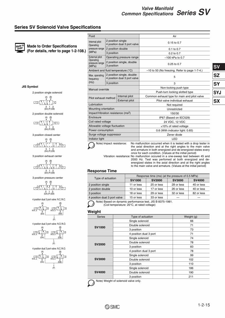
Series SV Solenoid Valve Specifications
Fluid
Ambient and fluid temperature (°C)
Manual override
Pilot exhaust method
Lubrication
Mounting orientation
Impact/Vibration resistance (ms2)
Enclosure
Coil rated voltage
Allowable voltage fluctuation
Power consumption
Surge voltage suppressor
Indiator light
Air
0.15 to 0.7
0.1 to 0.7
0.2 to 0.7
–100 kPa to 0.7
0.25 to 0.7
–10 to 50 (No freezing. Refer to page 1-7-4.)
5
3
Non-locking push type
Push-turn locking slotted type
Common exhaust type for main and pilot valve
Pilot valve individual exhaust
Not required
Unrestricted
150/30
IP67 (Based on IEC529)
24 VDC, 12 VDC
±10% of rated voltage
0.6 (With indicator light: 0.65)
Zener diode
LED
2 position single4 position dual 3 port valve
2 position double
3 position
Operating pressure range
2 position single, double3 position
2 position single, double4 position dual 3 port valve
3 position
Type of actuation
2 position single
2 position double
3 position
4 position dual 3 port valve
SV100011 or less
10 or less
18 or less
15 or less
SV200025 or less
17 or less
29 or less
33 or less
SV300028 or less
26 or less
32 or less
—
SV400040 or less
40 or less
82 or less
—
Internal pilotOperating pressure range(MPa)
External pilotOperating pressure range(MPa)
Max. operating frequency(Hz)
JIS Symbol
Internal pilot
External pilot
Response TimeResponse time (ms) (at the pressure of 0.5 MPa)
Series Type of actuation
Single solenoid
Double solenoid
3 position
4 position dual 3 port
Single solenoid
Double solenoid
3 position
4 position dual 3 port
Single solenoid
Double solenoid
3 position
Single solenoid
Double solenoid
3 position
SV1000
SV2000
SV3000
SV4000
Weight (g)
66
71
73
71
74
78
83
78
99
102
110
186
190
211
Weight
Note) Weight of solenoid valve only.
2 position single solenoid
2 position double solenoid
3 position closed center
3 position exhaust center
3 position pressure center
4 position dual 3 port valve: N.C./N.C.
4 position dual 3 port valve: N.O./N.O.
4 position dual 3 port valve: N.C./N.O.
(A)4
(B)2
5(EA)
1(P)
3(EB)
(A)4
(B)2
5(EA)
1(P)
3(EB)
(A)4
(B)2
5(EA)
1(P)
3(EB)
(A)4
(B)2
5(EA)
1(P)
3(EB)
(A)4
(A)4
(A)4
(A)4
(B)2
(B)2
(B)2
(B)2
5(EA)
1(P)
3(EB)
5(EA)
5(EA)
5(EA)
1(P)
1(P)
1(P)
SOL.bSOL.a 3(EB)
3(EB)
3(EB)
SOL.bSOL.a
SOL.bSOL.a
Made to Order Specifications(For details, refer to page 1-2-108.)
Note) Impact resistance: No malfunction occurred when it is tested with a drop tester in the axial direction and at the right angles to the main valve and armature in both energized and de-energized states every once for each condition. (Values at the initial period)
Vibration resisitance: No malfunction occured in a one-sweep test between 45 and 2000 Hz. Test was perfomed at both energized and de-energized states in the axial direction and at the right angles to the main valve and armature. (Values at the initial period)
1-2-15
Series SVValve Manifold Common Specifications
SV
SZ
SY
SYJ
SX
031203
v2356
v2848936
products tandards, m.
1_02_SV.qxd 04.6.16 14:29 Page 2-15
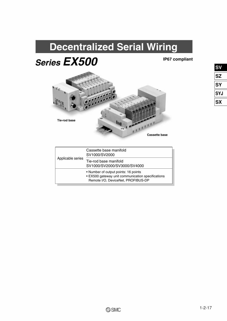
Decentralized Serial Wiring
Series EX500 IP67 compliant
Tie-rod base
Cassette base
Applicable series
Cassette base manifoldSV1000/SV2000
Tie-rod base manifoldSV1000/SV2000/SV3000/SV4000
• Number of output points: 16 points• EX500 gateway unit communication specifications
Remote I/O, DeviceNet, PROFIBUS-DP
1-2-17
SV
SZ
SY
SYJ
SX
1_02_SV.qxd 04.6.16 14:29 Page 2-17

Type of actuation
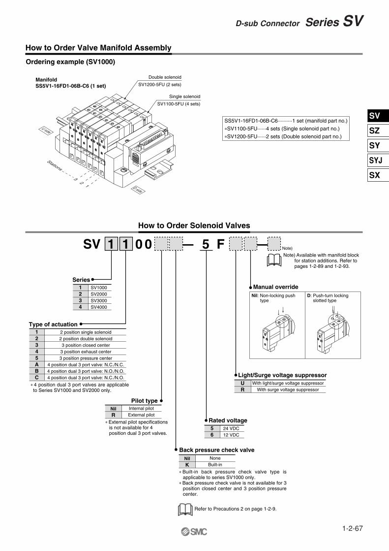
Back pressure check valve
How to Order Valve Manifold Assembly
Ordering example (SV1000)ManifoldSS5V1-W16SA1WD-06B-C6 (1 set)
SS5V1-W16SA1WD-06B-C6······1 set (Manifold part no.)
∗SV1100-5FU······4 sets (Single solenoid part no.)
∗SV1200-5FU······2 sets (Double solenoid part no.)
Manual override
Rated voltage
Nil: Non-locking push type
D: Push-turn locking slotted type
SV 1 1 0 0 F5
5 24 VDC
Light/Surge voltage suppressorWith light/surge voltage suppressor
With surge voltage suppressorUR
Pilot type
∗ External pilot specifications is not available for 4 position dual 3 port valves.
∗ 4 position dual 3 port valves are applicable to Series SV1000 and SV2000 only.
∗ Built-in back pressure check valve type is applicable to series SV1000 only.
∗ Back pressure check valve is not available for 3 position closed center and 3 position pressure
How to Order Solenoid Valves
Internal pilotExternal pilot
NilR
NoneBuilt-in
NilK
Series1234
SV1000SV2000SV3000SV4000
12345ABC
2 position single solenoid2 position double solenoid3 position closed center
3 position exhaust center3 position pressure center
4 position dual 3 port valve: N.C./N.C.4 position dual 3 port valve: N.O./N.O.4 position dual 3 port valve: N.C./N.O.
Note)
Double solenoid
SV1200-5FU (2 sets)
Single solenoid
SV1100-5FU (4 sets)
32
1
Stations
U side
D side
PWRCOM
DD
DD
DD
Refer to Precautions 2 on page 1-2-9.
Note) Available with manifold block for station additions. Refer to pages 1-2-89 and 1-2-93.
1-2-21
Series SVSeries EX500 Decentralized Serial Wiring
SV
SZ
SY
SYJ
SX
iedgth
cable series
V1000
V2000
V3000
V4000
longer rail tandard
pe ort ct
case of nly DIN ngs are ed.
products tandards, m.
1_02_SV.qxd 04.6.16 14:29 Page 2-21

Dedicated Output Serial Wiring
Series EX120
Applicable series
Cassette base manifoldSV1000/SV2000
Tie-rod base manifoldSV1000/SV2000/SV3000/SV4000
• Number of outputs points: 16 points
Tie-rod base
Cassette base
1-2-43
SV
SZ
SY
SYJ
SX
1_02_SV.qxd 04.6.16 14:29 Page 2-43

––
Type of actuation
A, B port size (Inch)A, B portSymbol
N1N3N7N3N7N9N7N9N11N9N1102N03N02T03TM
One-touch fitting for ø1/8"One-touch fitting for ø5/32"One-touch fitting for ø1/4"One-touch fitting for ø5/32"One-touch fitting for ø1/4"One-touch fitting for ø5/16"One-touch fitting for ø1/4"One-touch fitting for ø5/16"One-touch fitting for ø3/8"One-touch fitting for ø5/16"One-touch fitting for ø3/8"NPT 1/4NPT 3/8NPTF 1/4NPTF 3/8
∗ In the case of mixed specifications (M), indicate separately on the manifold specification sheet.∗ Port sizes of X, PE port for external pilot specification (R, RS) are ø4 (metric), ø5/32" (inch) for SV1000/2000 and ø6 (metric) and ø1/4" (inch) for SV3000/4000.
One-touchfitting for ø5/16"
P, E port Applicable series
SV1000
SV2000
SV3000
SV4000
One-touchfitting for ø3/8"
One-touchfitting for ø3/8"
One-touchfitting for ø3/8"
NPT 3/8
NPTF 3/8
A, B port size (Metric)A, B portSymbol
C3C4C6C4C6C8C6C8C10C8C10C120203
02F03FM
One-touch fitting for ø3.2One-touch fitting for ø4One-touch fitting for ø6One-touch fitting for ø4One-touch fitting for ø6One-touch fitting for ø8One-touch fitting for ø6One-touch fitting for ø8One-touch fitting for ø10One-touch fitting for ø8One-touch fitting for ø10One-touch fitting for ø12Rc 1/4Rc 3/8G 1/4G 3/8
One-touchfitting for ø8
P, E port Applicable series
SV1000
SV2000
SV3000
SV4000
One-touchfitting for ø10
One-touchfitting for ø12
One-touchfitting for ø12
Rc 3/8
G 3/8
How to Order Valve Manifold Assembly
Ordering example (SV1000)
ManifoldSS5V1-16S3AD-06B-C6 (1 set)
SS5V1-16S3AD-06B-C6········1 set (manifold part no.)
∗SV1100-5FU······4 sets (Single solenoid part no.)
∗SV1200-5FU······2 sets (Double solenoid part no.)
Manual override
Rated voltage
Nil: Non-locking pushtype
D: Push-turn lockingslotted type
SV 1 1 0 0 F5
5 24 VDC
Light/Surge voltage suppressorWith light/surge voltage suppressor
With surge voltage suppressorUR
Pilot type
∗ External pilot specifications is not available for 4 position dual 3 port valves.
∗ 4 position dual 3 port valves are applicable to Series SV1000 and SV2000 only.
∗ Built-in back pressure check valve type is applicable to Series SV1000 only. ∗ Back pressure check valve is not available for 3 position closed center and
3 position pressure center.
How to Order Solenoid Valves
Internal pilotExternal pilot
NilR
Back pressure check valveNoneBuilt-in
NilK
Series1234
SV1000SV2000SV3000SV4000
12345ABC
2 position single solenoid2 position double solenoid3 position closed center
3 position exhaust center3 position pressure center
4 position dual 3 port valve: N.C./N.C.4 position dual 3 port valve: N.O./N.O.4 position dual 3 port valve: N.C./N.O.
Note)
Double solenoid
SV1200-5FU (2 sets)
Single solenoid
SV1100-5FU (4 sets)
32
1
Stations
U side
D side
DD
DD
DD
Refer to Precautions 2 on page 1-2-9.
Note) Available with manifold block for station additions. Refer to pages 1-2-89 and 1-2-93.
A, B ports mixedA, B ports mixed
1-2-45
Series SVSeries EX120 Dedicated Output Serial Wiring
SV
SZ
SY
SYJ
SX
pecifiedgth
r
er
�-��S3SUH1SSL1SSL2SFU1SDN1SCS1SCS2SJN1SMJ1
longer rail tandard
e case of only DIN ttings are hed.
products tandards, m.
1_02_SV.qxd 04.6.16 14:29 Page 2-45

Circular Connector
Applicable series
Cassette base manifoldSV1000/SV2000
Tie-rod base manifoldSV1000/SV2000/SV3000/SV4000
• Number of connectors: 26 pins
IP67 compliant
Tie-rod base
Cassette base
1-2-55
SV
SZ
SY
SYJ
SX
plugged. ositions.
202.
917
2.9
MA
X.2
0
0-00-�gulator
107.
511
4.5
1_02_SV.qxd 04.6.16 14:29 Page 2-55

––
Back pressure check valve
Type of actuation
How to Order Valve Manifold Assembly
Ordering example (SV1000)
ManifoldSS5V1-W16CD-06B-C6 (1 set)
SS5V1-W16CD-06B-C6··········1 set (manifold part no.)
∗ SV1100-5FU······4 sets (Single solenoid part no.)
∗ SV1200-5FU······2 sets (Double solenoid part no.)
Manual override
Rated voltage
Nil: Non-locking pushtype
D: Push-turn locking slotted type
SV 1 1 0 0 F5
56
24 VDC12 VDC
Light/Surge voltage suppressorWith light/surge voltage suppressor
With surge voltage suppressorUR
Pilot type
∗ External pilot specifications is not available for 4 position dual 3 port valves.
∗ 4 position dual 3 port valves are applicable to Series SV1000 and SV2000 only.
∗ Built-in back pressure check valve type is applicable to series SV1000 only.
∗ Back pressure check valve is not available for 3 position closed center and 3 position pressure center.
How to Order Solenoid Valves
Internal pilotExternal pilot
NilR
NoneBuilt-in
NilK
Series1234
SV1000SV2000SV3000SV4000
12345ABC
2 position single solenoid2 position double solenoid3 position closed center
3 position exhaust center3 position pressure center
4 position dual 3 port valve: N.C./N.C.4 position dual 3 port valve: N.O./N.O.4 position dual 3 port valve: N.C./N.O.
Note)
Double solenoid
SV1200-5FU (2 sets)
Single solenoid
SV1100-5FU (4 sets)
32
1
Stations
U side
D side
DD
DD
DD
Refer to Precautions 2 on page 1-2-9.
Note) Available with manifold block for station additions. Refer to pages 1-2-89 and 1-2-93.
1-2-57
Circular Connector Series SV
SV
SZ
SY
SYJ
SX
DIN rail)DIN rail)
icable series
SV1000
SV2000
SV3000
SV4000
icable series
SV1000
SV2000
SV3000
SV4000
gth for 3 ions for e with 18
ely on the
R, RS) are etric) and
rail is desired tations.il than the
IN rail
an the
position Use of a is is not
manifold s cannot
products tandards, m.
1_02_SV.qxd 04.6.16 14:29 Page 2-57

D-sub Connector
Applicable series
Cassette base manifoldSV1000/SV2000
Tie-rod base manifoldSV1000/SV2000/SV3000/SV4000
• Number of connectors: 25 pins• MIL-C-24308Conforming to JIS-X-5101
Tie-rod base
Cassette base
1-2-65
SV
SZ
SY
SYJ
SX
e plugged. ositions.
2023 12.594.81441
ations
202.
917
2.9
MA
X.2
0
0-00-�gulator
107.
511
4.5
1_02_SV.qxd 04.6.16 14:29 Page 2-65
Back pressure check valve
Type of actuation
How to Order Valve Manifold Assembly
Ordering example (SV1000)
Manual override
Rated voltage
Nil: Non-locking pushtype
D: Push-turn locking slotted type
SV – –1 1 0 0 F5
56
24 VDC12 VDC
Light/Surge voltage suppressorWith light/surge voltage suppressor
With surge voltage suppressorUR
Pilot type
∗ External pilot specifications is not available for 4 position dual 3 port valves.
∗ 4 position dual 3 port valves are applicable to Series SV1000 and SV2000 only.
∗ Built-in back pressure check valve type is applicable to series SV1000 only.
∗ Back pressure check valve is not available for 3 position closed center and 3 position pressure center.
How to Order Solenoid Valves
Internal pilotExternal pilot
NilR
NoneBuilt-in
NilK
Series1234
SV1000SV2000SV3000SV4000
12345ABC
2 position single solenoid2 position double solenoid3 position closed center
3 position exhaust center3 position pressure center
4 position dual 3 port valve: N.C./N.C.4 position dual 3 port valve: N.O./N.O.4 position dual 3 port valve: N.C./N.O.
Note)
Refer to Precautions 2 on page 1-2-9.
Note) Available with manifold block for station additions. Refer to pages 1-2-89 and 1-2-93.
DD
DD
DD
ManifoldSS5V1-16FD1-06B-C6 (1 set)
SS5V1-16FD1-06B-C6··········1 set (manifold part no.)
∗SV1100-5FU······4 sets (Single solenoid part no.)
∗SV1200-5FU······2 sets (Double solenoid part no.)
D side
U side
Stations
12
3
Single solenoid
SV1100-5FU (4 sets)
Double solenoid
SV1200-5FU (2 sets)
1-2-67
D-sub Connector Series SV
SV
SZ
SY
SYJ
SX
iedh
tingth DIN rail)out DIN rail)
licable series
SV1000
SV2000
SV3000
SV4000
e, double, oid valves stations.sult in an
unused ed, order
specifica-on sheet. on valves solenoid
e length o 18 00, which 8 ximum.
ø6
onger s han the (Specify rail than
dard
ly DIN ached.
onger rail andard
products tandards, m.
1_02_SV.qxd 04.6.16 14:29 Page 2-67
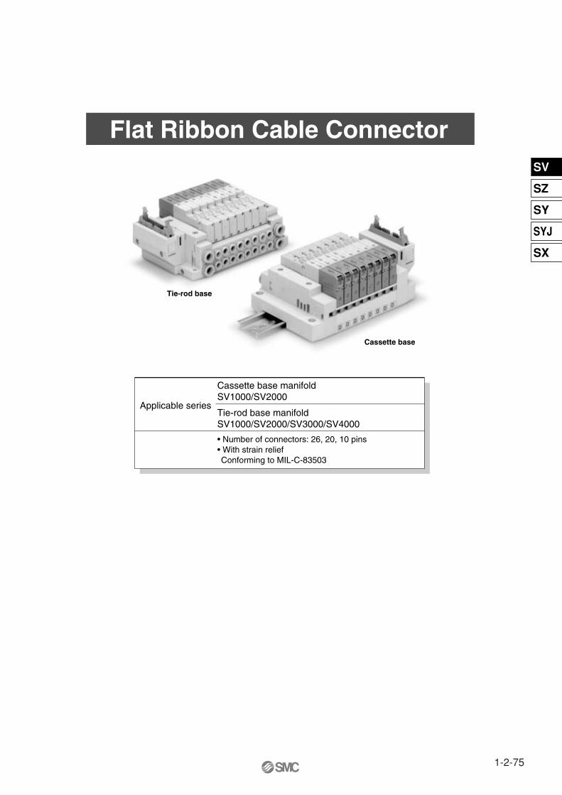
Flat Ribbon Cable Connector
Applicable series
Cassette base manifoldSV1000/SV2000
Tie-rod base manifoldSV1000/SV2000/SV3000/SV4000
• Number of connectors: 26, 20, 10 pins• With strain reliefConforming to MIL-C-83503
Tie-rod base
Cassette base
1-2-75
SV
SZ
SY
SYJ
SX
e plugged. ositions.
2010.500 69 2441
ations
202.
917
2.9
MA
X.2
0
00-00-�regulator
107.
511
4.5
1_02_SV.qxd 04.6.16 14:29 Page 2-75

Type of actuation
A, B port size (Inch)Symbol
N1N3N7N3N7N9N7N9N11N9N1102N03N02T03TM
One-touch fitting for ø1/8"One-touch fitting for ø5/32"One-touch fitting for ø1/4"One-touch fitting for ø5/32"One-touch fitting for ø1/4"One-touch fitting for ø5/16"One-touch fitting for ø1/4"One-touch fitting for ø5/16"One-touch fitting for ø3/8"One-touch fitting for ø5/16"One-touch fitting for ø3/8"NPT 1/4NPT 3/8NPTF 1/4NPTF 3/8
One-touchfitting for ø5/16"
P, E port Applicable series
SV1000
SV2000
SV3000
SV4000
One-touchfitting for ø3/8"
One-touchfitting for ø3/8"
One-touchfitting for ø3/8"
NPT 3/8
NPTF 3/8
A, B port size (Metric)A, B port A, B portSymbol
C3C4C6C4C6C8C6C8C10C8C10C120203
02F03FM
One-touch fitting for ø3.2One-touch fitting for ø4One-touch fitting for ø6One-touch fitting for ø4One-touch fitting for ø6One-touch fitting for ø8One-touch fitting for ø6One-touch fitting for ø8One-touch fitting for ø10One-touch fitting for ø8One-touch fitting for ø10One-touch fitting for ø12Rc 1/4Rc 3/8G 1/4G 3/8
One-touchfitting for ø8
P, E port Applicable series
SV1000
SV2000
SV3000
SV4000
One-touchfitting for ø10
One-touchfitting for ø12
One-touchfitting for ø12
Rc 3/8
G 3/8
How to Order Valve Manifold Assembly
Ordering example (SV1000)
ManifoldSS5V1-16PD1-06B-C6 (1 set)
SS5V1-16PD1-06B-C6··········1 set (manifold part no.)
∗SV1100-5FU······4 sets (Single solenoid part no.)
∗SV1200-5FU······2 sets (Double solenoid part no.)
Manual override
Rated voltage
Nil: Non-locking pushtype
D: Push-turn locking slotted type
SV – –1 1 0 0 F5
56
24 VDC12 VDC
Light/Surge voltage suppressorWith light/surge voltage suppressor
With surge voltage suppressorUR
Pilot type
∗ External pilot specifications is not available for 4 position dual 3 port valves.
∗ 4 position dual 3 port valves are applicable to Series SV1000 and SV2000 only.
∗ Built-in back pressure check valve type is applicable to series SV1000 only. ∗ Back pressure check valve is not available for 3 position closed center and 3
position pressure center.
How to Order Solenoid Valves
Internal pilotExternal pilot
NilR
Back pressure check valveNone
Built-inNilK
Series1234
SV1000SV2000SV3000SV4000
12345ABC
2 position single solenoid2 position double solenoid3 position closed center
3 position exhaust center3 position pressure center
4 position dual 3 port valve: N.C./N.C.4 position dual 3 port valve: N.O./N.O.4 position dual 3 port valve: N.C./N.O.
Note)
Double solenoid
SV1200-5FU (2 sets)
Single solenoid
SV1100-5FU (4 sets)
32
1
Stations
U side
D side
DD
DD
DD
Refer to Precautions 2 on page 1-2-9.
∗ In the case of mixed specifications (M), indicate separately on the manifold specification sheet.
∗ Port sizes of X, PE port for external pilot specification (R, RS) are ø4 (metric), ø5/32" (inch) for SV1000/2000 and ø6(metric) and ø1/4" (inch) for SV3000/4000.
Note) Available with manifold block for station additions. Refer to pages 1-2-89 and 1-2-93.
A, B ports mixedA, B ports mixed
1-2-77
Flat Ribbon Cable Connector Series SV
SV
SZ
SY
SYJ
SX
fied
ns
10 pins
ngns
youtpossible.)
the ons up r is 8
a longer the length.)
a manifold
(1)
(2)
tingth DIN rail)out DIN rail)
longer s than the d
(Specify rail than
dard
nly DIN ttached.
products tandards, m.
1_02_SV.qxd 04.6.16 14:29 Page 2-77
4 pins c
M12 W
N
M12waterproof connector
Rated voltage
Pilot type
How to Order
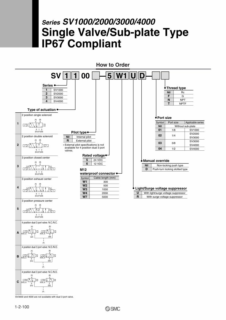
Series SV1000/2000/3000/4000Single Valve/Sub-plate Type IP67 Compliant
Type of actuation
SV – –W10011 5Series
1234
SV1000SV2000SV3000SV4000
Light/Surge voltage suppressorUR
With light/surge voltage suppressorWith surge voltage suppressor
Manual overrideNon-locking push type
Push-turn locking slotted typeNilD
56
24 VDC12 VDC
NilR
Internal pilotExternal pilot
SV3000 and 4000 are not available with dual 3 port valve.
U D
Port size
Thread type
SymbolNil01
02
03
04
1/8
1/4
3/8
1/2
Applicable series
SV1000SV2000SV3000SV3000SV4000SV4000
Port sizeWithout sub-plate
NilFNT
RcG
NPTNPTF
SymbolW1W2W3W4W7
Cable length (mm)
1
2
3
4
5
A
C
2 position single solenoid
2 position double solenoid
3 position closed center
3 position exhaust center
3 position pressure center
4 position dual 3 port valve: N.C./N.C.
4 position dual 3 port valve: N.O./N.O.
4 position dual 3 port valve: N.C./N.O.
B
(A)4
(B)2
5(EA)
1(P)
3(EB)
(A)4
(B)2
5(EA)
1(P)
3(EB)
(A)4
(B)2
5(EA)
1(P)
3(EB)
(A)4
(B)2
5(EA)
1(P)
3(EB)
(A)4
(A)4
(A)4
(A)4
(B)2
(B)2
(B)2
(B)2
5(EA)
1(P)
3(EB)
5(EA)
5(EA)
5(EA)
1(P)
1(P)
1(P)
SOL.bSOL.a 3(EB)
3(EB)
3(EB)
SOL.bSOL.a
SOL.bSOL.a
∗ External pilot specifications is not available for 4 position dual 3 port valves.
300500
100020005000
1-2-100
1_02_SV.qxd 04.6.16 14:30 Page 2-100
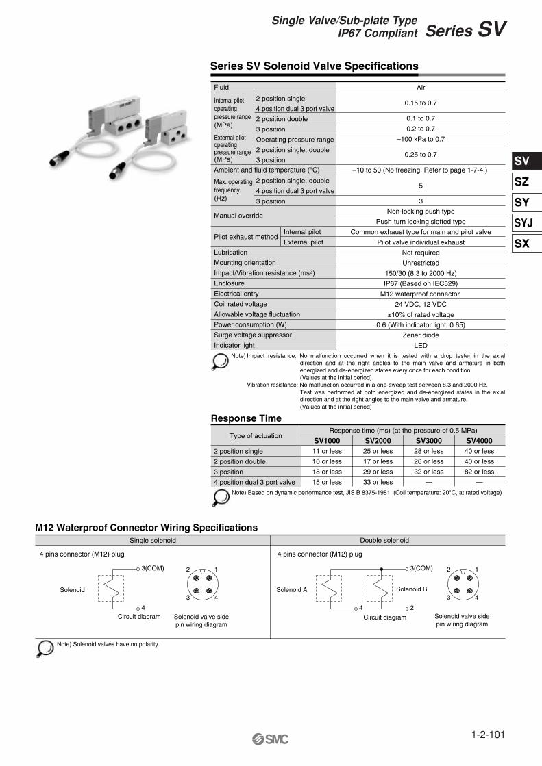
Series SV Solenoid Valve Specifications
Note) Based on dynamic performance test, JIS B 8375-1981. (Coil temperature: 20°C, at rated voltage)
Fluid
Ambient and fluid temperature (°C)
Manual override
Pilot exhaust method
Lubrication
Mounting orientation
Impact/Vibration resistance (ms2)
Enclosure
Electrical entry
Coil rated voltage
Allowable voltage fluctuation
Power consumption (W)
Surge voltage suppressor
Indicator light
Air
0.15 to 0.7
0.1 to 0.7
0.2 to 0.7
–100 kPa to 0.7
0.25 to 0.7
–10 to 50 (No freezing. Refer to page 1-7-4.)
5
3
Non-locking push type
Push-turn locking slotted type
Common exhaust type for main and pilot valve
Pilot valve individual exhaust
Not required
Unrestricted
150/30 (8.3 to 2000 Hz)
IP67 (Based on IEC529)
M12 waterproof connector
24 VDC, 12 VDC
±10% of rated voltage
0.6 (With indicator light: 0.65)
Zener diode
LED
2 position single
4 position dual 3 port valve
2 position double
3 position
Operating pressure range
2 position single, double
3 position
2 position single, double
4 position dual 3 port valve
3 position
Type of actuation
2 position single
2 position double
3 position
4 position dual 3 port valve
SV100011 or less
10 or less
18 or less
15 or less
SV200025 or less
17 or less
29 or less
33 or less
SV300028 or less
26 or less
32 or less
—
SV400040 or less
40 or less
82 or less
—
Internal pilotoperating pressure range(MPa)
External pilotoperating pressure range(MPa)
Max. operating frequency(Hz)
Internal pilot
External pilot
Response TimeResponse time (ms) (at the pressure of 0.5 MPa)
Single solenoid
4 pins connector (M12) plug 4 pins connector (M12) plug
Double solenoid
M12 Waterproof Connector Wiring Specifications
Note) Solenoid valves have no polarity.
3(COM)
4Circuit diagram Solenoid valve side
pin wiring diagram
2 1
3 4
Circuit diagram
2 1
3 4
Solenoid valve sidepin wiring diagram
Solenoid
4
Solenoid A
3(COM)
2
Solenoid B
Note) Impact resistance: No malfunction occurred when it is tested with a drop tester in the axial direction and at the right angles to the main valve and armature in both energized and de-energized states every once for each condition. (Values at the initial period)
Vibration resistance: No malfunction occurred in a one-sweep test between 8.3 and 2000 Hz. Test was performed at both energized and de-energized states in the axial direction and at the right angles to the main valve and armature. (Values at the initial period)
1-2-101
Series SVSingle Valve/Sub-plate Type IP67 Compliant
SV
SZ
SY
SYJ
SX
ries
1_02_SV.qxd 04.6.16 14:30 Page 2-101

2 pos
2 pos
3 pos
3 pos
3 pos
Cons
Comp
A
No.
q
w
e
r
t
y
u
Repla
No.
i
o
—
N
Flow Characteristics/Weight
Valve model Type of actuation
Flow characteristics (1)
1.0
0.77
0.73
1.2 [0.51]
0.68
0.87
0.30
0.28
0.31
0.24 [0.45]
0.35
0.31
0.24
0.18
0.18
0.29 [0.14]
0.18
0.23
1.1
0.85
1.1 [0.55]
0.89
1.1
0.77
0.30
0.30
0.26 [0.52]
0.47
0.39
0.44
0.26
0.19
0.24 [0.16]
0.24
0.29
0.21
1 � 4/2 (P � A/B) 4/2 � 5/3(A/B � EA/EB)
Weight (g) (2)
123 (88)
128 (93)
130 (95)
128 (93)
M12 waterproof connector (Cable length 300 mm)
Port size
Rc 1/8
Single
Double
Closed center
Exhaust center
Pressure center
N.C./N.C.
N.O./N.O.
2 position
3 position
4 position dual
Note 1) [ ]: Denotes the normal position. Note 2) ( ): Denotes without sub-plate.
SV1�00-�-01
Series SV1000
Series SV2000
Series SV3000
Series SV4000
C [dm3/(s·bar)] b Cv C [dm3/(s·bar)] b Cv
Type of actuation
Flow characteristics (1)
2.4
1.8
1.4
3.3 [0.84]
2.2
2.7
0.41
0.47
0.55
0.36 [0.60]
0.40
0.24
0.64
0.50
0.44
0.85 [0.28]
0.55
0.57
2.8
1.8
3.0 [1.2]
1.8
2.6
2.3
0.29
0.40
0.33 [0.48]
0.40
0.31
0.36
0.66
0.47
0.72 [0.37]
0.48
0.60
0.54
1 � 4/2 (P � A/B) 4/2 � 5/3(A/B � EA/EB)
Weight (g) (2)
159 (96)
163 (100)
168 (105)
163 (100)
M12 waterproof connector (Cable length 300 mm)
Port size
Rc 1/4
Single
Double
Closed center
Exhaust center
Pressure center
N.C./N.C.
N.O./N.O.
2 position
3 position
4 position dual
Valve model
SV2�00-�-02
C [dm3/(s·bar)] b Cv C [dm3/(s·bar)] b Cv
Type of actuation
Flow characteristics (1)
7.9
7.5
7.2
12 [3.3]
8.0
7.6
7.3
12 [3.3]
0.34
0.33
0.34
0.26 [0.41]
0.48
0.32
0.42
0.33 [0.51]
2.0
1.8
1.7
2.8 [0.84]
2.2
1.8
2.0
3.3 [0.94]
9.6
7.3
13 [4.0]
6.7
10
7.3
13 [4.7]
7.4
0.43
0.30
0.23 [0.41]
0.40
0.29
0.32
0.32 [0.54]
0.33
2.5
1.7
2.8 [0.95]
1.9
2.5
1.8
3.6 [1.5]
1.9
1 � 4/2 (P � A/B) 4/2 � 5/3(A/B � EA/EB)
Weight (g) (2)
505 (208)
509 (212)
530 (233)
484
488
509
M12 waterproof connector (Cable length 300 mm)
Port size
Rc 3/8
Rc 1/2
Single
Double
Closed center
Exhaust center
Pressure center
Single
Double
Closed center
Exhaust center
Pressure center
2 position
3 position
2 position
3 position
Valve model
SV4�00-�-03
SV4�00-�-04
C [dm3/(s·bar)] b Cv C [dm3/(s·bar)] b Cv
Type of actuation
Flow characteristics (1)
4.1
3.0
2.6
5.3 [2.3]
4.9
3.0
2.6
5.3 [2.3]
0.41
0.43
0.42
0.39 [0.49]
0.29
0.40
0.42
0.31 [0.51]
1.1
0.80
0.71
1.3 [0.65]
1.2
0.80
0.71
1.3 [0.64]
4.1
2.6
4.7 [1.7]
2.2
4.5
2.6
4.8 [1.7]
2.3
0.29
0.41
0.35 [0.48]
0.49
0.27
0.45
0.35 [0.48]
0.45
1.0
0.72
1.1 [0.49]
0.63
1.1
0.73
1.1 [0.34]
0.66
1 � 4/2 (P � A/B) 4/2 � 5/3(A/B � EA/EB)
Weight (g) (2)
250 (121)
253 (124)
26 (132)
235
238
246
M12 waterproof connector (Cable length 300 mm)
Port size
Rc 1/4
Rc 3/8
Single
Double
Closed center
Exhaust center
Pressure center
Single
Double
Closed center
Exhaust center
Pressure center
2 position
3 position
2 position
3 position
Valve model
SV3�00-�-02
C [dm3/(s·bar)] b Cv C [dm3/(s·bar)] b Cv
Note 1) [ ]: Denotes the normal position. Note 2) ( ): Denotes without sub-plate.
Note 1) [ ]: Denotes the normal position. Note 2) ( ): Denotes without sub-plate.
Note 1) [ ]: Denotes the normal position. Note 2) ( ): Denotes without sub-plate.
SV3�00-�-03
Series SV
1-2-102
1_02_SV.qxd 04.6.16 14:30 Page 2-102

2 position single
2 position double2 position double
3 position closed center
3 position exhaust center
3 position pressure center
2 position single
3 position closed center/exhaust center/pressure center
Construction: SV1000/2000/3000/4000 Tie-rod Base Type
Component Parts
(A)4
(B)2
5(EA)
1(P)
3 (EB)
(A)4
(B)2
5(EA)
1(P)
3 (EB)
(A)4
(B)2
5(EA)
1(P)
3 (EB)
(A)4
(B)2
5(EA)
1(P)
3 (EB)
(A)4
(B)2
5(EA)
1(P)
3 (EB)
Body
Adapter plate
Pilot body
Piston
End plate
Spool valve assembly
Molded coil
Aluminum die-casted
(SV1000 is zinc die-casted)
Resin
Resin
Resin
Resin
Aluminum/HNBR
—
Material Note
White
White
White
—
White
—
Gray
DescriptionNo.
q
w
e
r
t
y
u
u e r w q yt
u e r w q yt
u e r w q y t
Replacement Parts
Sub-plate
Gasket
Round head combination screw
SV1�00
SY3000-27-1�-Q
SY3000-11-25
SX3000-22-2(M2 x 24)
SV2�00
SY5000-27-1�-Q
SY5000-11-18
SV2000-21-1(M3 x 30)
SV3�00
1/4: SY7000-27-1�-Q
3/8: SY7000-27-2�-Q
SY7000-11-14
SV3000-21-1(M4 x 35)
SV4�00
3/8: SY9000-27-1�
1/2: SY9000-27-2�
SY9000-11-2
SV2000-21-2(M3 x 40)
DescriptionPart no.
Note
Aluminum die-casted
Refer to thread types on page 1-2-100 for �.
For valve mounting(Matt nickel plated)
No.
i
o
—
io1
(P)4(A)
2(B)
5(EA)
3(EB)
io1
(P)4(A)
2(B)
5(EA)
3(EB)
io1
(P)4(A)
2(B)
5(EA)
3(EB)
M2: 0.16 N·mM3: 0.8 N·mM4: 1.4 N·m
Note) Round head combination screw requires 2 pcs. per one valve for Series SV1000, SV2000, SV3000. For Series SV4000, it requires 3 pcs.
Mounting screw tightening torques
Caution
1-2-103
Series SVSingle Valve/Sub-plate Type IP67 Compliant
SV
SZ
SY
SYJ
SX
(g) (2)
88)
93)
95)
93)
connector 300 mm)
(g) (2)
6)
00)
05)
00)
connector 300 mm)
(g) (2)
08)
12)
33)
connector 300 mm)
(g) (2)
21)
24)
32)
connector 300 mm)
1_02_SV.qxd 04.6.16 14:30 Page 2-103
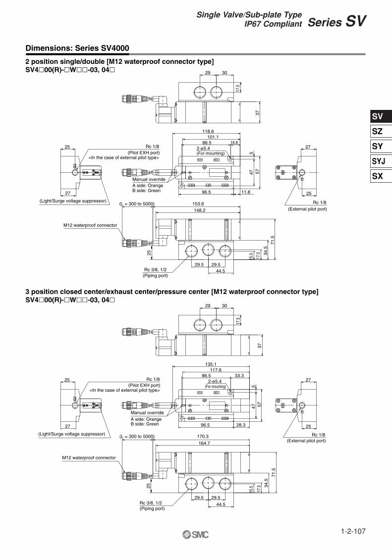
Dimensions: Series SV4000
2 position single/double [M12 waterproof connector type]SV4�00(R)-�W��-03, 04�
3 position closed center/exhaust center/pressure center [M12 waterproof connector type]SV4�00(R)-�W��-03, 04�
B
A
SMC
Manual override
A B
M12 waterproof connector
A side: OrangeB side: Green
X
Rc 1/8(External pilot port)
PE
Rc 1/8(Pilot EXH port)
<In the case of external pilot type>
(Light/Surge voltage suppressor)
5 EA 1 P 3 EB
B 2A 4
2-ø5.4(For mounting)
BA
SMC
Manual override
A B
M12 waterproof connector
A side: OrangeB side: Green
Rc 3/8, 1/2(Piping port)
X
Rc 1/8(External pilot port)
PE
Rc 1/8(Pilot EXH port)
<In the case of external pilot type>
(Light/Surge voltage suppressor)
5 EA 1 P 3 EB
B 2A 4
2-ø5.4(For mounting)
Rc 3/8, 1/2(Piping port)
37
(L = 300 to 5000)
29.5 29.544.5
15.5
17.5 34
.5
71.5
148.2153.8
27
25
25
27
547 57
11.8
101.1118.6
86.5
96.5
16.8
29
17.5
30
4737
(L = 300 to 5000)
29.5 29.5
44.5
15.5
17.5 34
.5
71.5
27
25
25
27
557
86.5
96.5
29
17.5
30
164.7
170.3
28.3
33.3117.6
135.1
2525
1-2-107
Series SVSingle Valve/Sub-plate Type IP67 Compliant
SV
SZ
SY
SYJ
SX
1_02_SV.qxd 04.6.16 14:30 Page 2-107
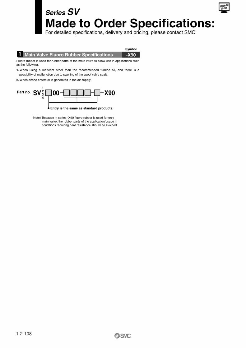
SV 00 X90
Entry is the same as standard products.
Part no.
Main Valve Fluoro Rubber Specifications -X90Symbol
Series SVMade to Order Specifications:For detailed specifications, delivery and pricing, please contact SMC.
1234
Fluoro rubber is used for rubber parts of the main valve to allow use in applications such as the following.
1. When using a lubricant other than the recommended turbine oil, and there is a
possibility of malfunction due to swelling of the spool valve seals.
2. When ozone enters or is generated in the air supply.
Note) Because in series -X90 fluoro rubber is used for only main valve, the rubber parts of the application/usage in conditions requiring heat resistance should be avoided.
1
1-2-108
1_02_SV.qxd 04.6.16 14:30 Page 2-108


![[sv] Validity date from LAND Vietnam 00269 [SV] SECTION ... · 2 / 33 [sv] List in force Godkännandenum mer Namn Ort [sv] Regions [sv] Activities [sv] Remark [sv] Date of request](https://img.pdfslide.us/doc/110x75/5d66deeb88c99332038b89d9/sv-validity-date-from-land-vietnam-00269-sv-section-2-33-sv-list.jpg)