Embed Size (px)
Citation preview

00
GMA PMI PRE First issue MHR
01
2008-11-14 SPO / NSH PMI PRE Overhauling following comments from SIP-PMU, KSK and RA
MHR
NSC CS-1 CONCEPT DESIGN SAFETY DOCUMENT
CHAPTER 4: DESIGN ORDER
ДОКУМЕНТ ПО БЕЗОПАСНОСТИ В РАМКАХ КОНЦЕПЦИИ
ПРОЕКТА ПК-1 НБК ГЛАВА 4 – ПОРЯДОК ПРОЕКТИРОВАНИЯ
S I P N L I 2 2 A 5 0 0 _ C D S 0 0 1 0 1
2008-07-04
Chernobyl New Safe Confinement – Contract N° SIP08- 1-001
NSC CS-1 CONCEPT DESIGN SAFETY DOCUMENT CHAPTER 4 – DESIGN ORDER
SIP-N-LI-22-A500_-CDS-001-01
Page 2 of 96
TABLE OF CONTENT
LIST OF FIGURES 5
LIST OF TABLES 6
LIST OF ABBREVIATIONS 7
4.1 ENGINEERING ORGANISATION 10
4.2 ENGINEERING STAGES, SCHEDULE AND PROCEDURES 12
4.2.1 ENGINEERING STAGES 12
4.2.1.1 Initial stages 12 4.2.1.2 Stages of the Detailed Design (according to decree # 421) 12 4.2.1.3 Working design (WD) 13 4.2.1.4 Construction, Commissioning, and Handing Over 13
4.2.2 DESIGN DEVELOPMENT: 13
4.2.3 DESIGN SCHEDULE 15
4.2.4 DESIGN PROCEDURES 18
4.2.4.1 General Engineering procedures 18 4.2.4.2 Radiological safety analyses integration 25
4.2.5 APPLICATION OF THE NORMATIVE DOCUMENTS 29
4.2.5.1 General Approach 29 4.2.5.2 Technical approach for DPs developed abroad 29 4.2.5.3 Specific approaches 30 4.2.5.4 Application of NPP-related norms 32
4.2.6 INTERFACES WITH CS2 DESIGN ACTIVITIES 32
4.3 METHODS AND MODELS USED FOR THE DESIGN 34
4.3.1 FOUNDATIONS 34
4.3.2 STEEL ARCH STRUCTURE 36
4.3.2.1 Fire resistance stability of the steel structure: 40 4.3.2.2 Tornado effects 41
4.3.3 CLADDING/ROOFING 43
4.3.4 MAIN CRANE SYSTEM 43
4.3.5 VENTILATION 43
Chernobyl New Safe Confinement – Contract N° SIP08- 1-001
NSC CS-1 CONCEPT DESIGN SAFETY DOCUMENT CHAPTER 4 – DESIGN ORDER
SIP-N-LI-22-A500_-CDS-001-01
Page 3 of 96
4.3.6 RADIATION PROTECTION 44
4.4 TESTING DURING THE DESIGN PROCESS 45
4.4.1 TEST OF CORROSIVITY 45
4.4.1.1 Presentation of the test 45 4.4.1.2 Execution of the test 45 4.4.1.3 Reports 45 4.4.1.4 Roof panel tests 45
4.4.2 WIND TUNNEL TEST 46
4.4.2.1 Introduction 46 4.4.2.2 Wind test methodology 46 4.4.2.3 Dimensioning load evaluation 48
4.4.3 PILE TEST 49
4.4.4 SOIL INVESTIGATION 50
4.5 QUALITY ASSURANCE DURING DESIGN 51
4.5.1 INTRODUCTORY STATEMENT 51
4.5.2 MANAGEMENT SYSTEM BASIS 51
4.5.3 REFERENCE DOCUMENT REVIEW 51
4.5.4 DOCUMENTATION OF THE OVERALL MANAGEMENT SYSTEM 52
4.5.5 GRADING THE REQUIREMENTS APPLIED TO MANAGEMENT SYSTEM 53
4.5.6 SATISFACTION OF INTERESTED PARTIES 53
4.5.7 ORGANISATIONAL POLICIES FOR QUALITY, SAFETY, ETC. 53
4.5.8 PLANNING 54
4.5.9 RESPONSIBILITY AND AUTHORITY FOR THE MANAGEMENT SYSTEM 54
4.5.10 RESOURCE MANAGEMENT 55
4.5.11 PROCESS IMPLEMENTATION 55
4.5.12 PROCESS MANAGEMENT 55
4.5.13 GENERIC MANAGEMENT SYSTEM PROCESSES 55
4.5.14 MEASUREMENT, ASSESSMENT AND IMPROVEMENT 57
4.5.15 JOB DESCRIPTIONS 57
4.6 DETAILED LICENSING DURING DETAILED DESIGN 64
Chernobyl New Safe Confinement – Contract N° SIP08- 1-001
NSC CS-1 CONCEPT DESIGN SAFETY DOCUMENT CHAPTER 4 – DESIGN ORDER
SIP-N-LI-22-A500_-CDS-001-01
Page 4 of 96
4.6.1 JUSTIFICATION OF THE LICENSING PROCESS 65
4.6.1.1 Review process for the NSC Design 65 4.6.1.2 Comparative schedule analysis 66 4.6.1.3 Comparative mobilisation analysis 71 4.6.1.4 Comparative project risk analysis 72 4.6.1.5 Conclusion – justification of the selection of the licensing process 73
4.6.2 COMPREHENSIVE STATE EXPERT REVIEW OF THE WORKING DOCUMENTS FOR CONSTRUCTION OF INFRASTRUCTURE FACILITIES TO ERECT NSC CS-1, LAY TEMPORARY FOUNDATIONS AND DECONSTRUCT VENTILATION STACK AND RA AUTHORIZATION TOWARDS IMPLEMENTATION OF THE WORKS 74
4.6.3 RA’S CONCURRENCE OF DOCUMENTS CONTAINING THE ADDITIONAL DESIGN CRITERIA, REQUIREMENTS AND INITIAL DATA FOR NSC CS-1 DESIGNING 75
4.6.4 REVIEW AND COMMENT OF RA ON DOCUMENTS FROM THE DESIGN SETS 78
4.6.5 COMPREHENSIVE STATE EXPERT REVIEW ON THE COMPLETE DESIGN DOCUMENTATION OF THE NSC-CS1 AND RA’S AUTHORISATION TO PROCEED WITH NSC CS-1 CONSTRUCTION 79
4.6.6 REGULATORY AGREEEMENT OF TECHNICAL SPECIFICATIONS FOR EQUIPMENT AND SYSTEMS RELATED TO RADIATION, NUCLEAR, FIRE AND INDUSTRIAL SAFETY 81
4.7 STATEMENT OF DESIGN IN ACCORDANCE WITH CRITERIA AND REQUIREMENTS 89
ATTACHMENTS TO CHAPTER 4 90
A 4.1 – LIST OF REFERENCES 91
A-4.2: APPLICATION OF NPP-RELATED NORMS 93
A-4.3. RECONCILIATION OF WESTERN NORMS 94
Chernobyl New Safe Confinement – Contract N° SIP08- 1-001
NSC CS-1 CONCEPT DESIGN SAFETY DOCUMENT CHAPTER 4 – DESIGN ORDER
SIP-N-LI-22-A500_-CDS-001-01
Page 5 of 96
LIST OF FIGURES
Figure 4.1-1. NOVARKA Project Organisation Chart – simplified presentation ......................... 11
Figure 4.2-1. Interaction stages of the NSC project (CS-1) with documents of safety assessment .............................................................................................................................. 28
Figure 4.3-1. SCAD soft. Certificate of Conformity.................................................................... 39
Figure 4.6-1. Schedule for Licensing Process 1 - All detailed design and working design activities submitted and reviewed together ............................................................................... 68
Figure 4.6-2. Schedule for Licensing Process 2 – Working Designs are reviewed separately... 69
Figure 4.6-3. Schedule for Licensing Process 3 – Working Designs are reviewed separately and the NSC Design is reviewed in two steps ................................................................................. 70
Figure 4.6-4. Comparison of the mobilisation requirements for each licensing process ............ 72

Chernobyl New Safe Confinement – Contract N° SIP08- 1-001
NSC CS-1 CONCEPT DESIGN SAFETY DOCUMENT CHAPTER 4 – DESIGN ORDER
SIP-N-LI-22-A500_-CDS-001-01
Page 6 of 96
LIST OF TABLES
Table 4.2-1. Main interfaces between systems 21 Table 4.2-2. Groups used for the sizing of cranes 32 Table 4.5-1. Baseline documents to be considered for the Designing process 52 Table 4.6-1. List of documents to be submitted to the Regulatory Authorities during and at the end of the Design 83
Chernobyl New Safe Confinement – Contract N° SIP08- 1-001
NSC CS-1 CONCEPT DESIGN SAFETY DOCUMENT CHAPTER 4 – DESIGN ORDER
SIP-N-LI-22-A500_-CDS-001-01
Page 7 of 96
LIST OF ABBREVIATIONS
AHU Air Handling Unit
CD Conceptual Design
CDSD NSC CS-1 Concept Design Safety Document
ChNPP Chernobyl Nuclear Power Plant
CMU Cabinet Ministers of Ukraine
COP Construction Organisation Plan
CP Check Point
CPT Cone Penetration Test
CS-1 First Commissioning Stage
CS-2 Second Commissioning Stage
CS-3 Third Commissioning Stage
DCR Design Criteria and Requirements
DP Design Packages
DSS Dust Suppression System
EBP-A, B Early Biddable Project, Packages A and B
EBRD European Bank for Reconstruction and Development
EIA Environmental Impact Assessment
EO Expert Organisations
FDS Fire Dynamics Simulator
FS Feasibility Study
HVAC Heating, Ventilation and Air Conditioning
IAEA International Atomic Energy Agency
IAG International Advisory Group
IAMS Integrated Automated Monitoring System
ICS Integrated Control System
IDC Inter-Disciplinary Check
IMS Information Measurement System
ISO International Organization for Standardization
IWD Identified Working Designs
KIEP Kiev Institute Energoproekt
MDE Maximum Design Earthquake
MHU Ministry of Health of Ukraine
NAEK National Atomic Energy Generating Company “Energoatom” of the Ministry of Fuel and Energy of Ukraine
ND Normative Documents
NIS No Impact on Safety

Chernobyl New Safe Confinement – Contract N° SIP08- 1-001
NSC CS-1 CONCEPT DESIGN SAFETY DOCUMENT CHAPTER 4 – DESIGN ORDER
SIP-N-LI-22-A500_-CDS-001-01
Page 8 of 96
NIISK Research Institute of Building Structures
NLA Normative Legislative Acts
NLD Normative & Legal Documents
NPP Nuclear Power Plant
NRS Nuclear and Radiation Safety
NSC New Safe Confinement
NVS New Ventilation Stack
OS Chernobyl NPP Object Shelter
OSPU General Sanitary Rules for Radiation Safety of Ukraine
P Probability
PER Potential Exposure Restriction
PL Permissible Limit
PLC Programmable Logical Controller
PMU Project Management Unit
PM Process Materials
PPE Personal Protective Equipment
PPS Physical Protection System
PuSO Special (Transport) Treatment Point
RA Regulatory Authorities
RAW Radioactive Waste
RDAS Reactor Department Auxiliary Systems
RIPM Respiratory Individual Protection Means
RM Radiological Monitoring
RMS Radiation Monitoring System
RS Radiation Safety
SACS State Architecture and Construction Supervisory (inspection body)
SAO Standard Access Order (for implementation work)
SAR Safety Analysis Report
SAS Sanitary Accommodation Space
SCR Sanitary Compliance Report
SD Sanitary Doghouse
SFMS Structures & Foundation Monitoring System
SIP Shelter Implementation Plan
SLRAW Short-Lived Radioactive Waste
SMS Seismic Monitoring System
SNF Spent Nuclear Fuel
SNRC State Nuclear Regulatory Committee of Ukraine
SPS Sewage Pumping Station
Chernobyl New Safe Confinement – Contract N° SIP08- 1-001
NSC CS-1 CONCEPT DESIGN SAFETY DOCUMENT CHAPTER 4 – DESIGN ORDER
SIP-N-LI-22-A500_-CDS-001-01
Page 9 of 96
SPZ Sanitary Protected Zone
SRAW Solid Radioactive Waste
SRS Safety Related System
SRWS Solid Radioactive Waste Storage
SSC Systems, Structures & Components
SSC IS Systems, Structures & Components Important to Safety
SSCR Self-sustained Chain Reaction
SSE ChNPP State Specialized Enterprise Chernobyl Nuclear Power Plant
SSTC NRS State Scientific and Technical Centre for Nuclear and Radiation Safety
TD Technical Decision
TR Technical Requirement
TUE Transuranium Elements
TV Television
UAB Unified Administrative Building
UCP Unit Control Panel
UDO Ukrainian Design Organisation
UPS Uninterruptible Power Supply
VS Ventilation Stack
VS-2 Ventilation Stack 2
WD Working Design
WEP Work Execution Plan
WP Work Place
Chernobyl New Safe Confinement – Contract N° SIP08- 1-001
NSC CS-1 CONCEPT DESIGN SAFETY DOCUMENT CHAPTER 4 – DESIGN ORDER
SIP-N-LI-22-A500_-CDS-001-01
Page 10 of 96
4.1 ENGINEERING ORGANISATION
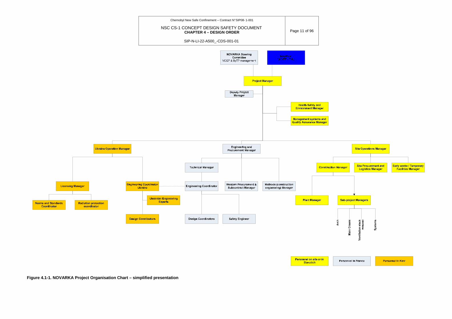
NOVARKA is an integrated joint venture constituted of VINCI Construction Grands Projets and Bouygues Travaux Publics. It is responsible as a whole for all Design aspects. Its Design teams are organised to ensure best efficiency during the whole engineering process and to make sure that normative and safety requirements will be considered. Therefore NOVARKA is acting as a Lead Designer.
Engineering activities will be carried out in 3 centres:
• Paris Office (Guyancourt): management and coordination team
• Kiev Office: licensing team and Ukrainian design coordination.
• Site Office: construction preparation
The main Design coordination and Design control tasks will be performed in Paris Offices by a core team composed of engineers, CAD operators and technical experts. Most of the engineering activities for Preliminary Design (the first stage of the Design, see section 4.2) will be performed by this core team. However some engineering tasks will be subcontracted to consultant organisations providing additional expertise in specific fields.
In order to avoid any risks to the most complicated systems, structures and components (SSC), NOVARKA made the choice to place, in some areas, several subcontracts for the same field of engineering. For instance, the preliminary design of the main cranes is being performed by two different and independent subcontractors. Upon completion of the preliminary Design, NOVARKA will select the best-in-class from both, in order to establish the procurement specification and initiate the second stage of Design and ultimately the crane manufacture.
Licensing and coordination team in Kiev office will coordinate the works performed by Ukrainian Design Organisations (UDO) which will be subcontracted for development of Design, and the other documents required by the Contract and necessary for licensing process.
NOVARKA is going to invite several UDOs to develop design documentation for specific fields of engineering. However, one Ukrainian Design Organisation will be selected which should perform an overall designing and integrate results of work of others into one unified Design set according requirements of DBN А.2.2-3-2004. This Ukrainian Design Organisation (Main Designer) will start its activity at the end of the first stage of the design process together with the Paris design team, to validate the selected design criteria and requirements of all engineering solutions.
NOVARKA, as the Lead Designer, will coordinate and check works performance of all the UDOs, according to the Integrated Management System Manual and Designing Plan.
The following chart presents NOVARKA’s design organisation (see Fig. 4.1-1).
Chernobyl New Safe Confinement – Contract N° SIP08- 1-001
NSC CS-1 CONCEPT DESIGN SAFETY DOCUMENT CHAPTER 4 – DESIGN ORDER
SIP-N-LI-22-A500_-CDS-001-01
Page 11 of 96
Figure 4.1-1. NOVARKA Project Organisation Chart – simplified presentation
Chernobyl New Safe Confinement – Contract N° SIP08- 1-001
NSC CS-1 CONCEPT DESIGN SAFETY DOCUMENT CHAPTER 4 – DESIGN ORDER
SIP-N-LI-22-A500_-CDS-001-01
Page 12 of 96
4.2 ENGINEERING STAGES, SCHEDULE AND PROCEDURES
4.2.1 ENGINEERING STAGES
4.2.1.1 Initial stages
NSC Feasibility Study (Conceptual Design – CD/FS) has been performed by the Consortium Bechtel / Battelle Memorial / EDF before issuing an invitation to tender. This Conceptual Design has been reviewed and approved by CMU with comments by the Regulatory Authorities and determination of items to be resolved by the NSC-CS1 Contractor. During the tendering period, in 2005, NOVARKA amended the Conceptual Design in its technical proposal.
The Conceptual Design was aiming to demonstrate that the project is feasible and preliminarily defining the economic cost of the NSC facility to be erected.
After the Conceptual Design, the International Advisory Group identified the Regulatory risk as the main risk of the Project. In order to mitigate this risk, a joint decision has been made by ChNPP with endorsement by SNRCU to develop Concept Design Safety Document (CDSD).
The CDSD is subject to concurrence by the Regulatory Authorities.
In parallel with the development of the CDSD, NOVARKA has updated the concepts of its technical proposal and included them in the CDSD. To this effect NOVARKA is developing some other documents (computation models, calculations, technical descriptions, general drawings, etc.) which together with CDSD will serve as input documents for the second stage of the design. This phase is called in some documents first stage of design, or Preliminary Design (see section 4.2.2) and will be used as input for the following engineering stage.
4.2.1.2 Stages of the Detailed Design (according to decree # 421)
Right after the Conceptual Design is the Detailed Design. The Detailed Design is an activity which includes detailed engineering and design works necessary to obtain licensing and to support construction, installation, and commissioning activities.
According to Decree #421 of the Cabinet of Ministers of Ukraine [3], the Detailed Design of NSC CS-1 is composed of two following stages for the arch, foundations, coating, roofing and its auxiliary systems and facilities:
• Design (D) is the development of design documentation according DBN А.2.2-3-2004, as well as the other documents necessary for licensing process in order to obtain permissions by regulatory and supervising authorities for NSC construction activities. At this stage NOVARKA with UDO will develop and submit to the Employer the following main documents: Design according DBN А.2.2-3-2004, SAR, EIA and SCR, and technical specifications for equipment. NOVARKA will submit the Design along with other main documents to the Employer for review and approval. After that the Employer will submit those documents to State Complex Expert Review. Due to the particularity of the Contract, this stage will be called second stage of design
• Working Documentation (W) is developed by NOVARKA in cooperation with UDO and subcontractors for separate systems/works on the basis of approved Design for implementation of construction and installation activities and submitted to SIP-PMU/ChNPP prior to commencement of the works.
As per Cabinet of Ministers of Ukraine Decree #1269 dated 31.10.2007 “On Procedure of Approval of Investment Programs and Construction Designs and Performance of their State

Chernobyl New Safe Confinement – Contract N° SIP08- 1-001
NSC CS-1 CONCEPT DESIGN SAFETY DOCUMENT CHAPTER 4 – DESIGN ORDER
SIP-N-LI-22-A500_-CDS-001-01
Page 13 of 96
Expert Review” the Working Documentation is subject to the state expert review in case that a part of it does not meet the earlier approved design decisions or in case if it is anticipated by the legislative deeds.
4.2.1.3 Working design (WD)
In order to speed up the construction and meet the overall schedule of the NSC-CS1 programme, NOVARKA proposes with SIP-PMU agreement and in accordance with the Licensing Plan, to perform Working Design for infrastructure facilities for construction of the NSC CS-1, ventilation stack removal, foundations in the assembly and sliding area.
WD is a one-step design phase and consists of two parts – approving part and working drawings. Approving part is subject to concurrence, expertise and approval, and working drawings are developed for object construction.
4.2.1.4 Construction, Commissioning, and Handing Ov er
The design team will be involved during the performance of the Works in order to manage issues related to changes, non conforming dispositions, justifications of new technical decisions, resolutions, development of as built documentation and reports.
4.2.2 DESIGN DEVELOPMENT
During the first stage - Preliminary Design - NOVARKA collects and substantiates the initial data, design criteria and requirements and the functional specifications.
At this stage modelling and calculations of the steel structures and NSC foundations shall be performed as well as Terms of Reference for the Design of the main cranes etc. will be developed. NOVARKA experts shall elaborate basic engineering solutions for all the systems and will check their interfaces and interaction.
The experts from the Ukrainian Design Organisations will join NOVARKA core design team at the final stage of Preliminary Design. The main task of that joint design team will be checking of correctness of the chosen design criteria and their substantiation, and clarification of essential architectural and engineering solutions, and checking the input data and computation models and calculation results, and Design Packages interface clarification, etc.
Preliminary Design will be the set of documents which consists of: CDSD approved by the Employer and RA, reports on calculation results of the Arch steel structures and cladding/roofing, as well as of main foundations, and preliminary technical specifications of the main cranes, layout drawing of the NSC major facilities, preliminary architectural and structural solutions of technological building and auxiliary buildings, and the design solutions for NSC auxiliary facilities, systems preliminary designs, etc. During the development of preliminary project the questions of safety substantiations will be taken into account. It will be base for development SAR, EIR and SCR. All subcontractors must have the necessary licenses regulated by the legislation of Ukraine.
Preliminary Design documentation will be handed over to the Ukrainian Main Designer and to other UDOs at the second stage of the designing to ensure Design completion.
During the second stage of Design, the UDO and subcontractors and under NOVARKA supervision will develop the Design and assist for preparation of the technical specifications for procurement, as well as SAR, EIA, and SCR (by UDO specially contracted).
The Main Designer essential tasks will be:
Chernobyl New Safe Confinement – Contract N° SIP08- 1-001
NSC CS-1 CONCEPT DESIGN SAFETY DOCUMENT CHAPTER 4 – DESIGN ORDER
SIP-N-LI-22-A500_-CDS-001-01
Page 14 of 96
• to verify the Preliminary Design data and to check their conformance with design criteria and
requirements of Ukrainian codes and standards, CDSD and NSC CS-1 Contract;
• to integrate design solutions developed by NOVARKA and other UDOs;
• to develop technical specifications and other documents according to Preliminary Design and NSC CS-1 Contract;
• to develop Design in accordance with DBN А.2.2-3-2004;
• to interface with NOVARKA’s licensing team to ensure link with the UDO developing SAR, EIA and SCR taking into account safety analyses and evaluations when developing integrated design decisions and submitting all the necessary information to design organizations for detail design of separate facilities and systems; and
• to support NOVARKA during period of the State Complex Expert Review.
NOVARKA as the Lead Designer shall arrange and monitor interfaces of the core design team in Paris and the Main Designer and other UDO in order to ensure continuity of engineering solutions adopted at the first design stage during Design development and further NSC CS-1 implementation.
NOVARKA will submit the above mentioned documents to the Employer via SIP-PMU for review. After its approval the Employer will submit this set of design documents to the State Complex Expert Review. NOVARKA will support the Employer on the stage of the State Complex Expert Review of the Design.
The third phase of the detailed design works – Working Documentation - W – will be done by NOVARKA, UDO and other subcontractors based on the Design approved by the Ministry of Emergencies in established order.
Also at this stage (W) NOVARKA will issue Invitations For Tender (IFT) for procurement of NSC systems and components. These IFTs are based on Technical Specifications completed at the Design stage (D).
At the Design stage (D) NOVARKA will develop and submit to the Employer via SIP-PMU for review and approval the following documents:
• Industrial Safety & Health Program (during operation), and
• Fire Safety Plan (during operation).
The Design activities will encompass safety analysis aimed to identify the provisions to be made so that the NSC is safe, in other terms, that the exposure to radiation of personnel, public and environment are kept within defined limits in normal, off-normal and accidental conditions.
NOVARKA will conduct all design related activities according to IMS Manual and Designing Plan.
Design organizations that perform design of NSC CS-1 will perform design supervision during construction, installation and commissioning of NSC CS-1 in accordance with the requirements of Ukrainian legislation.
Possibility of Design development and its concurrence in two steps should be considered here. The two-step licensing process is described in more details in Section 4.6 below.
Chernobyl New Safe Confinement – Contract N° SIP08- 1-001
NSC CS-1 CONCEPT DESIGN SAFETY DOCUMENT CHAPTER 4 – DESIGN ORDER
SIP-N-LI-22-A500_-CDS-001-01
Page 15 of 96
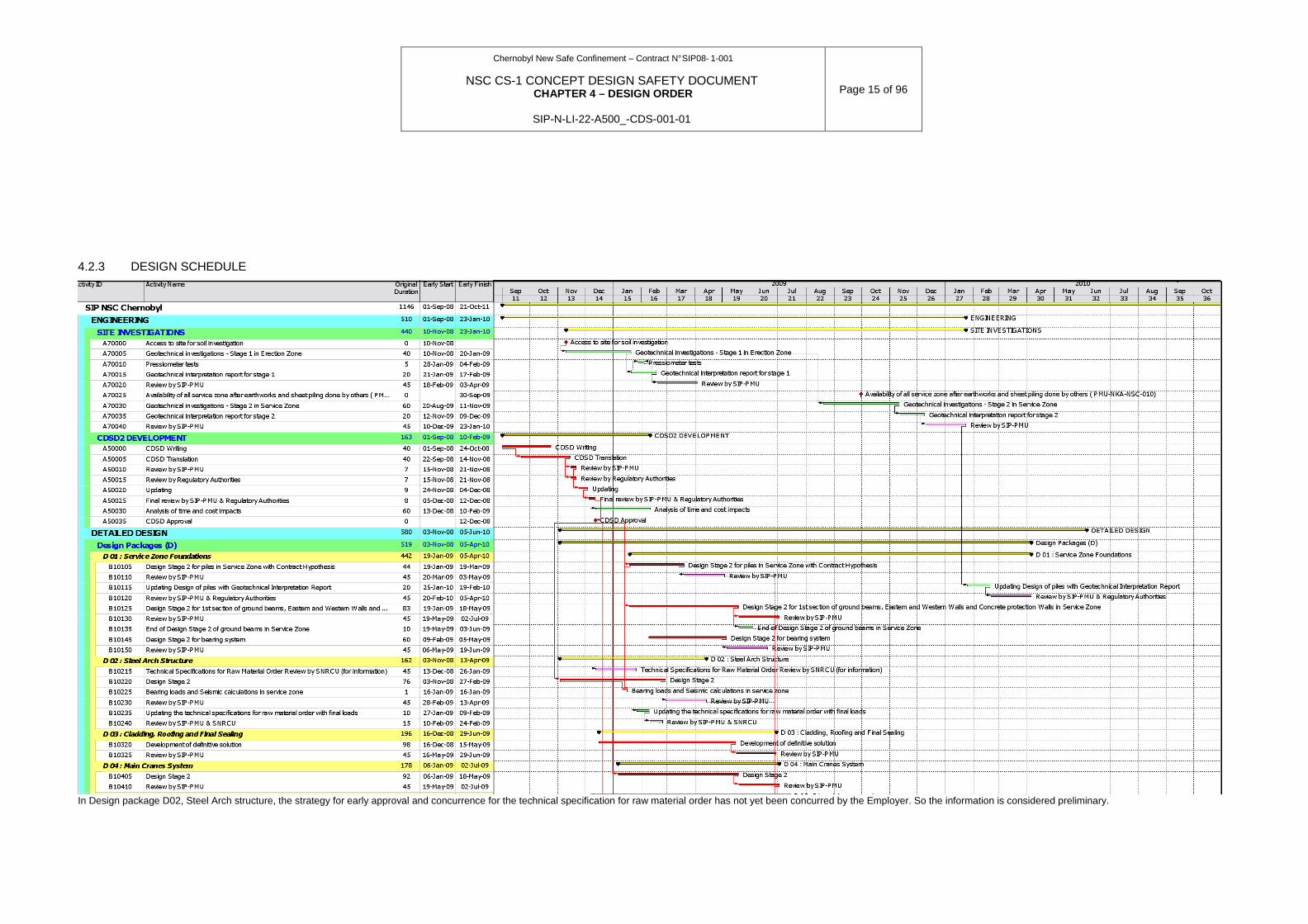
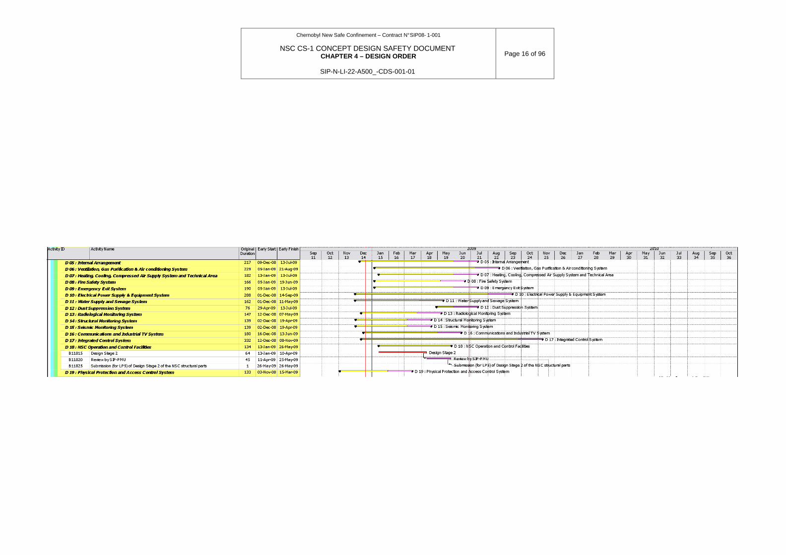
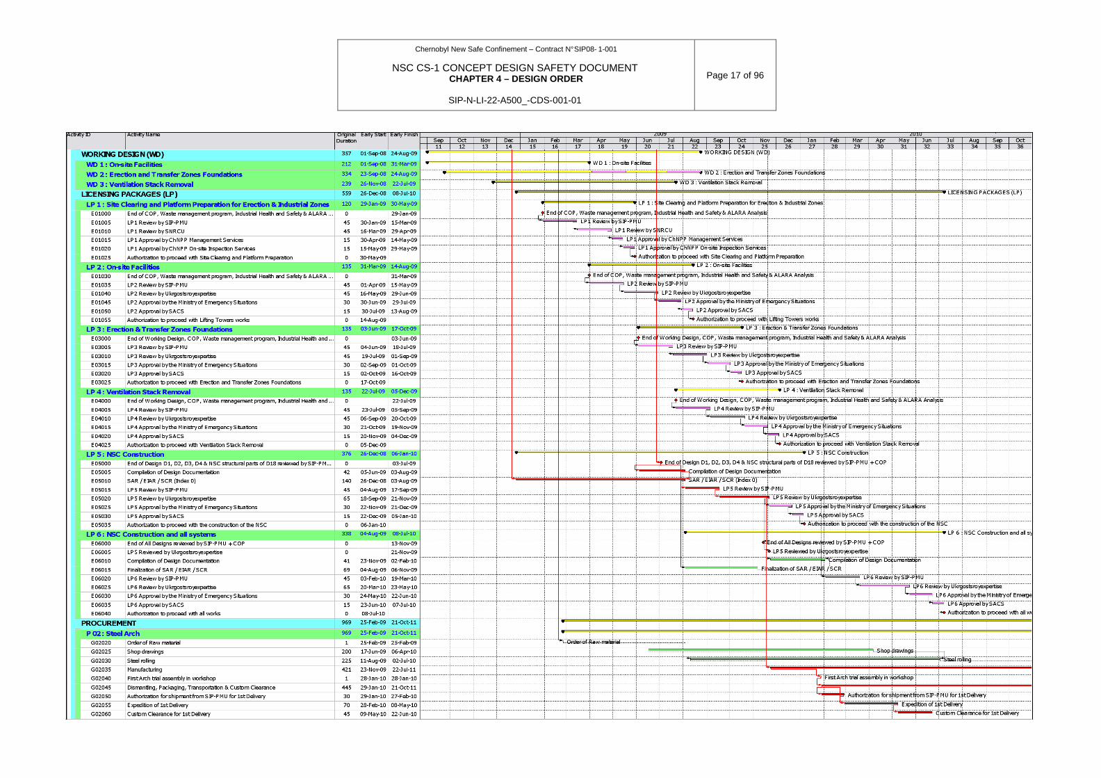
4.2.3 DESIGN SCHEDULE
In Design package D02, Steel Arch structure, the strategy for early approval and concurrence for the technical specification for raw material order has not yet been concurred by the Employer. So the information is considered preliminary.
Chernobyl New Safe Confinement – Contract N° SIP08- 1-001
NSC CS-1 CONCEPT DESIGN SAFETY DOCUMENT CHAPTER 4 – DESIGN ORDER
SIP-N-LI-22-A500_-CDS-001-01
Page 16 of 96
Chernobyl New Safe Confinement – Contract N° SIP08- 1-001
NSC CS-1 CONCEPT DESIGN SAFETY DOCUMENT CHAPTER 4 – DESIGN ORDER
SIP-N-LI-22-A500_-CDS-001-01
Page 17 of 96

Chernobyl New Safe Confinement – Contract N° SIP08- 1-001
NSC CS-1 CONCEPT DESIGN SAFETY DOCUMENT CHAPTER 4 – DESIGN ORDER
SIP-N-LI-22-A500_-CDS-001-01
Page 18 of 96
4.2.4 DESIGN PROCEDURES
4.2.4.1 General Engineering procedures
The tasks defined in the Strategy P10 [2] have been grouped into coherent sets of design activities which are called DP. They have been identified on the basis of the contents of the NSC FS (CD). These DPs are:
• DP1 - Foundations
This DP includes engineering activities for the structures i.e.
− foundations in the local area,
− foundations in the Arch assembly and transfer areas;
− foundations for the infrastructure facilities on site used to assemble the Arch;
− foundations of the technological and auxiliary buildings.
It will mainly consist of the structural calculations to define the minimum characteristics of piles and structures so as to sustain the load cases described in Section 2.4, according to the requirements from Section 2.6.3. It will also encompass the definition of the main dimensions of the foundations and the characteristics of the concrete and rebars to construct them, as well as provisions to ensure their durability.
• DP2 - Steel arch structure
This DP includes mainly the design decisions for the structural elements of the NSC (arch chords, diagonals, bracings, purlins, main cranes support beams, access platforms and other structures) in terms of resistance, rigidity and durability. They allow housing various systems inside the NSC in order to ensure the required functions (see design criteria in Section 2.4).
• DP3 - Cladding & roofing
This DP includes all activities related to define the various cladding materials, the assembly methodology, implementation techniques and the fire resistance and maintenance requirements for the inner cladding and roofing of the NSC. It also defines the means required to decontaminate and repair the cladding. It includes calculations of the cladding resistance to stresses and the definition leak tightness and durability requirements.
• DP4: Main cranes system
This DP is self explanatory. It aims to define the characteristics of the main cranes including the telescopic mast and its integration within the NSC in order to allow the deconstruction process.
• DP5: Internal arrangement and Indoor transportation
This DP aims to define:
− the location and size of the rooms constituting the technological building, the auxiliary buildings, the north and south truck airlocks and the internal arrangement of the main NSC facility,
− the definition of the initial treatment area, lay-down area and preparation area;
− the decontamination facilities and the maintenance facilities located inside the main NSC facilities and the technological building;
− the lifts, staircases and corridors enabling personnel to circulate inside all the buildings;
Chernobyl New Safe Confinement – Contract N° SIP08- 1-001
NSC CS-1 CONCEPT DESIGN SAFETY DOCUMENT CHAPTER 4 – DESIGN ORDER
SIP-N-LI-22-A500_-CDS-001-01
Page 19 of 96
− the handling equipment used in the initial treatment area, the preparation area and the
laydown area which will be used to transfer the unstable structures to the lorries used to transport them to the ChNPP solid waste management facilities.
• DP6 – Ventilation, Gas Purification and Air conditionning
This DP aims to develop the ventilation system for the main NSC facility (main volume and annular space) and for the other buildings (auxiliary buildings and technological building). It will also include the emergency ventilation system developed to control the releases following any deviation from normal operation or accident, and the smoke exhaust system.
This DP will also encompass definition of tie-in points for the CS2 and SO systems.
• DP7 - Heating, cooling, and compressed air supply system
This DP aims to supply heating or cooling water and compressed air. It includes circulation of those utilities throughout the main NSC facilities.
This DP will also encompass definition of tie-in points for the CS2 and SO systems.
• DP8 – Fire safety
This DP encompasses application of the main normative requirements in terms of main structure resistance to fire events, room protection and arrangement. It also covers implementation of fire-detection, alarm and fire extinguishing means.
This DP will also encompass definition of tie-in points for the CS2 and SO systems.
• DP9 - Emergency exits
This DP aims to develop the main implication of emergency situation management to the layout of the main NSC facility, technological building and auxiliary building. It will define the emergency pathways and the associated utilities (lighting, protection, breathable air supply…).
• DP10 - Power supply
This DP aims to develop the electrical power supply network throughout the main NSC facility including definition of:
− Normal power supply;
− Redundant power supply;
− Permanent power supply;
− Lighting;
− Grounding;
− Lightning protection;
− Arrangement of cable trays;
• DP 11 - Water supply and sewage
This DP aims to develop coherently:
− the supply of industrial and potable water,
− the supply of firewater,
− the sanitary sewage,
− the sewage of industrial water;
− the sewage of storm water,
Chernobyl New Safe Confinement – Contract N° SIP08- 1-001
NSC CS-1 CONCEPT DESIGN SAFETY DOCUMENT CHAPTER 4 – DESIGN ORDER
SIP-N-LI-22-A500_-CDS-001-01
Page 20 of 96
− the sewage of LRAW and its management.
It will define the collection points, the provisions made to avoid mixing effluents of different radiological nature and the connection to the ChNPP system.
This DP will also encompass definition of tie-in points for the CS2 and SO systems.
• DP12 - Dust suppression
This DP shall be developed in case the existing dust suppression system (DSS) preparation plant has to be modified. As long as no modification is planned, its scope of activities is limited to ensure that access to the existing plant will be kept operational.
• DP13 – Radiological monitoring
This DP aims to define the requirements of the radiological monitoring system which is part of the ICS according to the Strategy for NSC Implementation. It will define the radiological monitoring sensors, their location and their interaction with the other systems of the facility in particular the ICS.
This DP will also encompass definition of tie-in points for the CS2 and SO systems.
• DP14 - Structural monitoring
This DP aims to define the requirements of the structural monitoring system which is part of the ICS according to the Strategy for NSC Implementation. It will define the structural monitoring sensors, their location and their interaction with the other systems of the facility in particular the ICS.
This DP will also encompass definition of tie-in points for the CS2 and SO systems.
• DP15 – Seismic monitoring
This DP aims to define the requirements of the seismic monitoring system which is part of the ICS according to the Strategy for NSC Implementation. It will define the seismic monitoring sensors, their location and their interaction with the other systems of the facility in particular the ICS.
This DP will also encompass definition of tie-in points for the CS2 and SO systems.
• DP16 - Communications, alarm, notification and industrial TV
This DP aims to define the various communication, alarm, notification and industrial TV means, the parameters which they monitor and their interaction with the other systems of the facility. The method of such notification must be agreed with NFSD. It should also be provided measures for the prevention and limitation of truck fire.
• DP17 - Integrated control system
This DP aims to develop the overall Instrumentation and Control architecture of the NSC CS-1 including:
− The receipt, processing and storing of the data on parameters characterizing the technology process behaviour and the state of the technology equipment;
− The determination of the actual and/or anticipated (forecasted) deviations of the technology parameters from the set or permitted ones;
− The reflection of the data in format suitable for perception and analysis by the operative personnel;
− The performance of the visual and audible signals for operators at revelation of the deviations from the parameters and in other specified cases;
− The control of other systems state;

Chernobyl New Safe Confinement – Contract N° SIP08- 1-001
NSC CS-1 CONCEPT DESIGN SAFETY DOCUMENT CHAPTER 4 – DESIGN ORDER
SIP-N-LI-22-A500_-CDS-001-01
Page 21 of 96
− The archiving and/or registration of the data and personnel actions;
− The preparation and release of the data to the other information systems and/or receipt of data from these systems.
• DP18 - Operation and control facilities and technological building
This DP aims to define the civil works of the auxiliary and technological building. It is mostly civil works design with consideration for the load cases defined in section 2.4. This DP will also consider the general layout issues.
• DP19 - Physical protection system
This DP aims to develop the interaction of the NSC with the Physical Protection and Access Control System of ChNPP.
• SAR, EIR, SCR
This DP aims to justification of the safety issues when designing, assembling, constructing, commissioning and operating of NSC.
All these DPs are developed in parallel in order to optimise the total duration of the Project. One of the main aims of the Preliminary Design is to determine the overall scope of each engineering task (DP) and its main design criteria providing consideration of interface requirements. For instance:
• The Arch is designed with envelope values for the constraints generated by the main cranes (mass of main cranes, maximum horizontal and vertical crane loads, overall geometry…) defined in their preliminary design.
• The foundations are designed with an envelope value of the Arch loads applied on the pot bearings defined in the preliminary design of the steel structure of Arch.
• The integrated control system is based on a plug-in architecture allowing for easy connection of all the other systems of the facility.
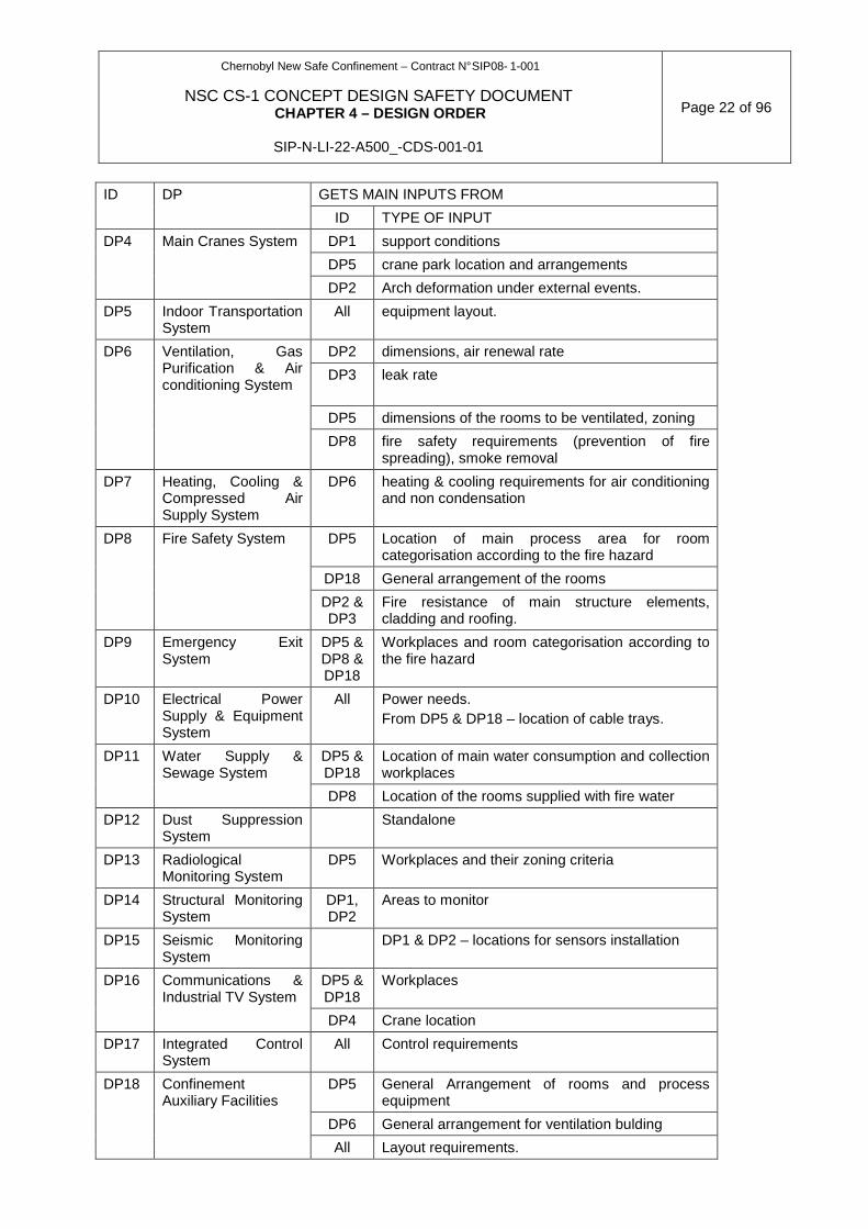
The following table shows the main interfaces between systems (non limitative list).
Table 4.2-1. Main interfaces between systems GETS MAIN INPUTS FROM ID DP
ID TYPE OF INPUT
DP1 Foundations & sliding system
DP2 mass of the arch, loads on pot bearings
DP1 Foundations stiffness and damping (matrices)
DP4 loads + location + dimensions.
DP3 Mass, pressure applied
DP2 Steel Arch Structure
Others (DP5, DP6, DP18
…)
layout constraints + local weights + support frames…
DP2 dimensions and shape, displacements/strains at panel support points
DP3 Cladding & Roofing
DP6 temperature and air leak criteria
Chernobyl New Safe Confinement – Contract N° SIP08- 1-001
NSC CS-1 CONCEPT DESIGN SAFETY DOCUMENT CHAPTER 4 – DESIGN ORDER
SIP-N-LI-22-A500_-CDS-001-01
Page 22 of 96
GETS MAIN INPUTS FROM ID DP
ID TYPE OF INPUT
DP1 support conditions
DP5 crane park location and arrangements
DP4 Main Cranes System
DP2 Arch deformation under external events.
DP5 Indoor Transportation System
All equipment layout.
DP2 dimensions, air renewal rate
DP3 leak rate
DP5 dimensions of the rooms to be ventilated, zoning
DP6 Ventilation, Gas Purification & Air conditioning System
DP8 fire safety requirements (prevention of fire spreading), smoke removal
DP7 Heating, Cooling & Compressed Air Supply System
DP6 heating & cooling requirements for air conditioning and non condensation
DP5 Location of main process area for room categorisation according to the fire hazard
DP18 General arrangement of the rooms
DP8 Fire Safety System
DP2 & DP3
Fire resistance of main structure elements, cladding and roofing.
DP9 Emergency Exit System
DP5 & DP8 & DP18
Workplaces and room categorisation according to the fire hazard
DP10 Electrical Power Supply & Equipment System
All Power needs. From DP5 & DP18 – location of cable trays.
DP5 & DP18
Location of main water consumption and collection workplaces
DP11 Water Supply & Sewage System
DP8 Location of the rooms supplied with fire water
DP12 Dust Suppression System
Standalone
DP13 Radiological Monitoring System
DP5 Workplaces and their zoning criteria
DP14 Structural Monitoring System
DP1, DP2
Areas to monitor
DP15 Seismic Monitoring System
DP1 & DP2 – locations for sensors installation
DP5 & DP18
Workplaces DP16 Communications & Industrial TV System
DP4 Crane location
DP17 Integrated Control System
All Control requirements
DP5 General Arrangement of rooms and process equipment
DP6 General arrangement for ventilation bulding
DP18 Confinement Auxiliary Facilities
All Layout requirements.

Chernobyl New Safe Confinement – Contract N° SIP08- 1-001
NSC CS-1 CONCEPT DESIGN SAFETY DOCUMENT CHAPTER 4 – DESIGN ORDER
SIP-N-LI-22-A500_-CDS-001-01
Page 23 of 96
GETS MAIN INPUTS FROM ID DP
ID TYPE OF INPUT
NOVARKA will only provide a free space in the technological building for the Access Control System (around 70m²)
DP19 Physical Protection & Access Control System
DP9 Location of emergency exits.
When developing the SAR, EIR, and SCR it shall be justified that the NSC components and systems under development meet the normative requirements. If the chosen option of NSC component realization does not meet the design criteria the corrective measures shall be performed in order to meet the criteria and the new option of NSC component realization shall be included into the appropriate document on safety justification.
The most affected DPs are those centralising important volumes of information from other packages (General Arrangement, steel Arch structure, Electric Power Supply System and Integrated Control System). Preliminary interface architecture and layout drawings will be developed early in the Design stage 2 (D). They will be based on:
• Good engineering judgement combined with experience in the field;
• Detailed knowledge of the normative requirements;
• Preliminary versions of the DP (from the Conceptual Design and from NOVARKA’s technical proposal).
These preliminary documents will provide general estimates of the main dimensions of buildings and systems and will help to define Design criteria in terms of encumbrance and locations for the systems and components to be provided by other DPs. In the case those criteria cannot be met, the general layout and interface architecture will be updated.
For instance, in order to avoid late consideration of interfaces, layout engineering (industrial architecture) will early delimit cable galleries, shielded or unshielded pipe galleries inside the technological building, providing all necessary access routes with regards to fire and radiation hazards.
From a structural point of view, the crossed constraints at the interface between the Arch Structure and its foundations will be solved using either integrated models of the Arch and its foundations according to [17] or interface resolution matrices. Both solving techniques are under assessment and comparison at the time of the CDSD development. The solving technique which will be selected for the Design is the one which proves the most appropriate in terms of feasibility, reliability and time scale.
This assessment and further calculations will be developed by NOVARKA and checked for compliance with local legislation by an UDO.
Management of the interfaces during Design progress
As stated before, the preliminary design phase aims to provide the different DPs with the basic information needed from other DPs considering envelope values or requirements. All along the progress of the development of the DPs, more accurate items of information for these interfaces are issued. As all systems and structures are developed more or less in parallel, the key point for the success of the Project is to manage and check the evolution of these ‘items of interface’ information.
In the engineering team, the Engineering coordinator checks in a regular manner the consideration of the interfaces in the development of each DP, to ensure that the design progress of a system or structure does not question the Design of others systems or structures. In a similar way and periodically, each Design Coordinator will check that his inputs for his
Chernobyl New Safe Confinement – Contract N° SIP08- 1-001
NSC CS-1 CONCEPT DESIGN SAFETY DOCUMENT CHAPTER 4 – DESIGN ORDER
SIP-N-LI-22-A500_-CDS-001-01
Page 24 of 96
system or structure coming from other engineering fields are still acceptable. For example, the progress of the Design of the Main Cranes will be carefully followed by the Engineering Coordinator and the Steel Structure DP Coordinator, to be sure that the Main Crane loads considered for the calculation of the steel arch remains envelope.
Coordination meetings are held on a weekly basis for this purpose. These meetings involve all the DP Coordinators when they are to make a general review of all interfaces of the Project. They may also be limited to a group of DP Coordinators when the purpose of the meeting is to deal with a particular interface. For example, coordination meetings for the Main Crane (including the garage) / steel Arch interface are periodically held with the DP Coordinators of the Steel Arch (with his design subcontractor) of the Main Crane , and with the Engineer in charge of the arrangement of the Main Crane garage.
Inter Disciplinary Check (IDC) of Design Documents before issuing to the Employer are implemented within NOVARKA design core team. The choice of performing an IDC review is kept to the DP Coordinator and the Engineering Manager. IDC review shall be limited to documents for which high interface level is necessary, for other small interferences direct communication shall be kept. The DP Coordinator is responsible for obtaining comments from recipients in due time. For further revisions of engineering documents, the IDC is performed only if judged necessary by the DP Coordinator.
Licensing Packages
All Design Packages will be compiled by the UDO into Licensing Packages. Six Licensing Packages will be provided:
• LP1 – Site clearing and platform preparation for er ection and industrial zones. This package encompasses the COP and/or WEP for all these operations, the associated industrial health and safety measures and procedures, a radioactive waste management plan, a radiation safety programme and a quality surveillance programme.
• LP2 – on-site facilities . This package includes the Working Design for infrastructure facilities (designed as defined in DBN A.2.2-3-3004 and associated working drawings), a construction organisation plan, the associated industrial health and safety measures and procedures, a radiological safety section and a radioactive waste management plan.
• LP3 – erection and transfer zone foundations . This package includes the Working Design for the foundations in the assembly and transfer areas (designed as defined in DBN A.2.2-3-3004 and associated working drawings), a construction organisation plan, the associated industrial health and safety measures and procedures, a radiological safety section and a radioactive waste management plan.
• LP4 – ventilation stack removal . This package includes the Working Design for the ventilation stack removal (designed as defined in DBN A.2.2-3-3004 and associated working drawings), a construction organisation plan, the associated industrial health and safety measures and procedures, a radiological safety section and a radioactive waste management plan.
• LP5 – first set of the Design . This package includes the first step of the Design as defined in section 4.6.1. Its structure and contents has to be concurred by the Regulatory Authorities prior to the submission. Table 4.6.1 presents a standard format proposed by NOVARKA,
• LP6 – Design of the NSC, Technological Building, Au xiliary Buildings and Systems, Utilities. This licensing package contains he Design of the NSC CS-1 according to DBN A.2.2-3-2004 including its construction organisation plan, the SAR, the EIA and the SCR.
Chernobyl New Safe Confinement – Contract N° SIP08- 1-001
NSC CS-1 CONCEPT DESIGN SAFETY DOCUMENT CHAPTER 4 – DESIGN ORDER
SIP-N-LI-22-A500_-CDS-001-01
Page 25 of 96
4.2.4.2 Radiological safety analyses integration
Radiological safety is defined as the ability of a facility (the NSC) or any activity (construction, commissioning, operation) to be performed while keeping the radiation impact to personnel, public and environment, below sets thresholds for normal, off-normal and accidental situations.
The radiological safety analysis aims to demonstrate that the requirements relating to radiological safety are exhaustively identified and considered in the NSC design, construction, commissioning and operation.
The radiological safety analysis encompasses the main following steps:
• Identification of the radiological hazards . These are the hazards which arise from the presence of radioactive materials in the NSC or nearby the Works area. These are mainly the dissemination of radioactive materials and the external exposure to radiation. Routine exposure to radiation is considered in all steps.
• Identification of the design events . Any event likely to occur or to be initiated by the construction, commissioning and operation (hereafter referred to as Works) activities will be listed in the list of design events. The events will be classified depending on their nature and origin as follows:
• Internal events . These events mostly arise from uncontrolled deviation of operation parameters of the NSC or Works equipment, accidental situations such as a fire, the failure of any item of equipment (load dropping in case of crane failure) or personnel errors. These hazards might, in some circumstances, lead to the release of radioactive materials or to uncontrolled external exposure to radiation;
• External events . These events mostly arise from the environment or from human activities nearby the NSC and the Works site. These can be normal, off-normal or accidental climatic conditions (wind, snow, rain…), natural phenomena (earthquake, flooding, tornado…) or man-caused accidents (explosion, fire, truck collision, toxic gas cloud…). Regarding OS collapse, please refer to §2.3.3.2.
• Hazard assessment : the assessment is mostly based on the comparison with the values specified in the normative documents such as NRBU-97/D-2000. The following scheme represents the approach to be applied in the design process:
• The first step of the assessment is to identify if a hazard has to be taken into account in the design. It relies on estimates of the probability of occurrence of the hazard and its potential consequences. If the probability does not exceed 5x10⁻⁷/y or if an event is addressed with a routine technological process (normal operation) and consequently meets the associated exposure limitation, the hazard is stated acceptable and no provisions are made to prevent it or limit its potential consequences.
• After the potential consequences of the hazard are known, structures, systems or components which failure induce the hazard are pre-classified using the classification method presented in Section 2.6. This pre-classification will also consider the functions carried out. By this pre-classification, Design requirements are defined and are applied to the concerned SSC. The functions of the seismic monitoring system are also considered here.
• For those hazards which require further assessment (unacceptable risks), a reliability target is defined and provisions are made either to prevent their occurrence (prevention measures) or to limit their potential consequences (protection measures). The level of reliability and respective safety measures will be determined considering the integrated probability of potential exposures. These
Chernobyl New Safe Confinement – Contract N° SIP08- 1-001
NSC CS-1 CONCEPT DESIGN SAFETY DOCUMENT CHAPTER 4 – DESIGN ORDER
SIP-N-LI-22-A500_-CDS-001-01
Page 26 of 96
measures are implemented in addition to the Design requirements arising from the pre-classification. Both provisions can be implemented at the same time. The deterministic approach will be implemented as far as it is economically or technically viable; this viability will be determined based on good engineering judgement and application of best engineering practices. It aims to avoiding completely the occurrence of the radiological consequences. An example of such approach is the requirement not to use flammable materials as far as achievable to avoid fire risk in sensitive areas and to use quick suppression means to limit the radiological consequences of the fire either directly (the fire re-suspends radioactive materials) or indirectly (the fire damages an equipment, the failure of which may lead to re-suspension of radioactive materials).
• Iteratively, the residual consequences (consequences after the implementation of the prevention and protection measures) are calculated. The calculation of the residual consequences will take into account both the external and internal exposures and the exposure of public and environment. Various models extracted from the literature available (for instance the Shelter Safety Status Report) will be used as far as achievable to determine the amount of radioactivity suspended and the consequences incurred by the operation personnel, public and environment. This calculation will take into account the use of personnel protection equipment. A dispersion model and other required models will also be used to estimate the consequences of the hazard beyond the boundaries of the NSC.
• Together with the consequences, the probability of occurrence of the hazard will be calculated. For this, a fault tree or an event tree will be established to the maximum extent. At the early stage of the Design, preliminary probability values will be used for each event constituting the fault tree. These probability values will be completed with more accurate ones at later stages. Those accurate values extracted from open literature and available normative documents will, in the end, be specified as manufacturing criteria for suppliers.
• Once the total of the probabilities for a given consequent range complies with Table 2.2 of NRBU-97/D-2000; the hazard will be stated as being properly taken into account in the Design. . Probabilities and consequences of potential exposure will further be reduced according to ALARA principle.
• All the structures, systems and components which have been involved in the hazard assessment either because their failure is bound with the hazard or because they have been implemented as prevention or protection measures will then be definitely classified as defined in Section 2.6. This approach will allow applying additional design requirements if any.
• Identification of the monitoring requirements . The organisation and technical protection measures made and the systems, structures and components implemented to limit the consequences of hazards or to prevent their occurrence will be subject to monitoring assessment in order to determine:
• Which parameter have to be monitored and recorded all along the facility lifetime;
• What systems or procedures and with which reliability level have to be implemented to monitor properly the parameters (monitoring measures);
• Which deviations have to be detected to initiate prevention or protection measures (detection measures).
• Definition of the safety requirements. The safety requirements are of various natures:
• Technical requirements: structures, systems or components implemented as prevention, protection, monitoring and detection measures;
Chernobyl New Safe Confinement – Contract N° SIP08- 1-001
NSC CS-1 CONCEPT DESIGN SAFETY DOCUMENT CHAPTER 4 – DESIGN ORDER
SIP-N-LI-22-A500_-CDS-001-01
Page 27 of 96
• Organisational requirements: operations to be carried out in the framework of the
prevention, protection, monitoring and detection measures.
• Definition of the QA programme implemented to meet the safety requirements . The implementation of safety requirements will require application of QA programme dedicated to the manufacturing, construction, commissioning and operation. The QA programme implemented to meet the safety requirements will be developed specifically for each safety-important system. They include follow-up of documentations, identification of workshop or laboratory tests, checking of the consistency between the workshop or laboratory tests with the design requirements and tracking of the information. Section 4.5 describes the QA programme in the Design.
• Identification of tests important to safety . Such tests will be required for all systems, structures and elements, in accordance with the norms, rules and standards in effect in Ukraine, and/or reliability and strength of which cannot be guaranteed by the QA programme implemented to meet the safety requirements. For critical components, these tests can also be performed independently from the results of the QA programme. Similar tests could also be initiated to validate theoretical assumptions made in the Design, to supersede the absence of representative values or parameters in the open literature. Those tests will be carried out in workshops, on mock-ups or models or directly on site during commissioning. The preliminary list of these tests will be defined during the Design and submitted for concurrence by the Regulatory Authorities.^
Chernobyl New Safe Confinement – Contract N° SIP08- 1-001
NSC CS-1 CONCEPT DESIGN SAFETY DOCUMENT CHAPTER 4 – DESIGN ORDER
SIP-N-LI-22-A500_-CDS-001-01
Page 28 of 96
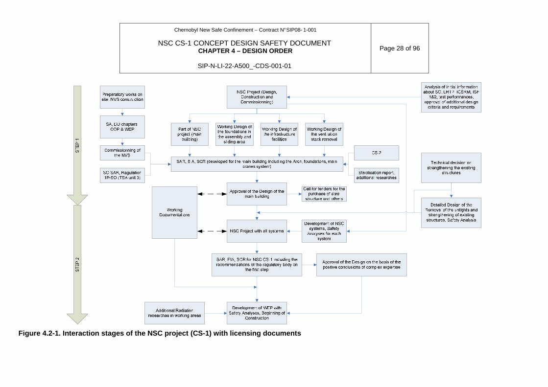
Figure 4.2-1. Interaction stages of the NSC project (CS-1) with licensing documents
Chernobyl New Safe Confinement – Contract N° SIP08- 1-001
NSC CS-1 CONCEPT DESIGN SAFETY DOCUMENT CHAPTER 4 – DESIGN ORDER
SIP-N-LI-22-A500_-CDS-001-01
Page 29 of 96
4.2.5 APPLICATION OF THE NORMATIVE DOCUMENTS
4.2.5.1 General Approach
In parallel with the safety analysis, NOVARKA will implement a dedicated strategy so that the NSC complies with the Ukrainian laws, codes, norms and standards in-force at the time when the NSC will be handed over to ChNPP. In order to meet this requirement:
NOVARKA’s design documents shall comply with Ukrainian legislation applicable at the handing over to the Employer. For this, NOVARKA in its Kiev office has established the detailed data base which is available to all the engineers and which will be permanently complemented and kept up-to-date. In the case the legislative and normative framework changes, NOVARKA will thus be able to inform the Employer of the changes and the impact to the Design will be estimated. In the case such change modifies the Design Criteria and Requirements, a Technical Decision will be produced and submitted to the Regulatory Authorities via and by the Employer. This Excel file includes all shortcuts and links to Russian, Ukrainian or English version of the codes, norms, laws and standards whenever available.
The technical approach concerning codes, norms, laws and standards depends on the concerned DP and the location where they will be developed. The distribution between UDO and Western Contractors of DPs will be done after the Preliminary Design (which is performed mostly in Western countries). Anyway, the following DPs will be developed in abroad:
• The foundations;
• The structural steel of the Arch;
• The cladding and roofing;
• The main cranes.
The DPs developed by UDO will consider the Ukrainian Normative requirements at the earliest stage of their development until the end of the Design. NOVARKA will thus rely on the acknowledged know-how and licenses of the UDO.
4.2.5.2 Technical approach for DPs developed abroad
For all DPs developed overseas, NOVARKA has established a framework to have them compliant with the Ukrainian norms and standards at the earliest possible stage of the Design. In the mean time, foreign regulations and standards will be applied initially in order to facilitate the interactivity between design coordinators and Western experts involved in the process. This includes during the Preliminary Design:
• Identification of the Western Norms which would have been applied for similar project overseas;
• Identification of applicable Ukrainian Norms and Standards, based on the following approach.
− Lists of documents given in Attachment 2.1 are used as a base and are complemented by all normative and legislative documents referenced in all Contract Attachments;
− This list will be kept up to date and complemented to cover all the structures, systems and components. Additional codes, norms and standards will be added to it for all matters relevant to construction, manufacture and commissioning tests, in particular for the Working Documentation stage.
Chernobyl New Safe Confinement – Contract N° SIP08- 1-001
NSC CS-1 CONCEPT DESIGN SAFETY DOCUMENT CHAPTER 4 – DESIGN ORDER
SIP-N-LI-22-A500_-CDS-001-01
Page 30 of 96
• Identification of the main Design Criteria and Requirements from the Ukrainian norms and
standards which are more constraining that the Western equivalent.
The Design will rely on this set of criteria and requirements which combine the most stringent of both Western and Ukrainian norms. Once the Western designers have completed their contribution to the Design, UDO will receive this contribution and compare it to the Ukrainian norms and standards to demonstrate compliance. Any additional requirements from Ukrainian norms and standards will then be applied to the Design and their impact to other DPs will be assessed and considered.
If foreign regulations and standards procedure are foreseen for application, it will be done according to the following circumstances:
• There is a lack of national normative documents, specifying the appropriate technical requirements;
• Application of foreign normative documents gives sufficient advantage to ensure higher level of operability and quality level of materials, equipment and structures than those stated in corresponding regulations and standards of Ukraine.
• Foreign normative document being equivalent to the corresponding national normative document since it establishes operational characteristics and quality standards of materials, equipment and structures provides significant advantages of costs and/or terms of implementation without deterioration of other quality standards of the facility under construction and first of all its reliability.
If application of foreign norms is foreseen, the design will be subject to the reconciliation in compliance with the requirements of the Employer and corresponding Regulatory Authority.
4.2.5.3 Specific approaches
This item provides brief information on Eurocodes that NOVARKA plan to apply during the design. It must be borne in mind that these Design provisions will be subject to review and amendment by UDO (URDISC) to demonstrate compliance with Ukrainian norms and standards. These documents will be applied provided that the requirements of the above section are met and respective concurrences from SSE ChNPP and Regulatory Authorities are obtained in the future. In the CDSD, this item is for information only and not subject to concurrence by SSE ChNPP and Regulatory Authorities.
Cladding:
The corrugated metal decking will be firstly checked according to EN 1993-1-3 “Design of steel structure – Part 1.3: General rules – Supplementary rules for cold-formed members and sheeting”.
The elements constitutive of the cladding and roofing will be designed according to Eurocode EN 1993.
In addition it will meet the requirement of DBN 2.6.14-97
Foundations and steel structure:
The design criteria are based on the document CDSD, Chapter 2
The design codes for loads and actions are based on Eurocode EN 1991 with adaptations to local load and wind actions on the Chernobyl site given by the regulations.
Wind aerodynamic coefficients initially calculated from EN 1991-4 will be obtained more precisely from the wind tunnel tests.

Chernobyl New Safe Confinement – Contract N° SIP08- 1-001
NSC CS-1 CONCEPT DESIGN SAFETY DOCUMENT CHAPTER 4 – DESIGN ORDER
SIP-N-LI-22-A500_-CDS-001-01
Page 31 of 96
Tornado effects will be analysed both by the partial factor method and the probabilistic method according to EN 1990.
Some updated Ukrainian standards like DSTU B.1.2-3-2006: Deflection and displacement – National standard of Ukraine, have also been used.
The structural steel sections will be checked according to the relevant sections of Eurocode EN 1993.
For the foundation design, the following Eurocode norms will be used:
• EN 1997 for foundations with the French application document NF EN 1997-1/NA, completed by fascicule 62 titre V of CCTG, as recommended by French administration’s document dated January,2008 : «Calcul des ponts aux EC, utilisation du fasc 62 titre V”;
• EN 1998 for design of structures for earthquake resistance;
• EN 1992-1 for reinforced concrete structures;
• EN206 for concrete mix design and other EN Norms for concrete components.
The Eurocode norms have been used for the following reasons:
• EC is a set of harmonised design code covering all aspects of civil Engineering;
• Most recent code offering best international practice;
• Coherent with product, execution and test standards (EN ISO);
• Assurance of high operational safety for involved parties;
• Recognised as an efficient code worldwide ;
• Possibility to use alternative reliability based design methods for exceptional situations (case of tornado class 3).
In order to check the conformity of the design according the Ukrainians Norms and Standards, the following reconciliation method will be performed:
• Involvement of Ukrainian Institutes with the relevant specialists to check the process;
• Comparison of loads, actions, coefficients, safety factors;
• Calculation comparison for critical elements, load combinations, governing cases;
• Agreement on final design provisions, dimensioning and issue reconciliation reports.
Attachment A4.3 presents practically the tasks carried out to make sure that the steel structure meets the Ukrainian normative requirements.
Main Cranes:
The Main Cranes System will be designed in accordance with the latest applicable:
• Ukrainian norms and standards;
• NPAOP 0.00-1.01-07: Rules for the construction and safe operation of the climbing cranes.
The minimum sizing of cranes shall comply with the following group classification.
The European FEM complements the requirements of the aforementioned NPAOP wherever required as defined in section 4.2.5.1 above.
Chernobyl New Safe Confinement – Contract N° SIP08- 1-001
NSC CS-1 CONCEPT DESIGN SAFETY DOCUMENT CHAPTER 4 – DESIGN ORDER
SIP-N-LI-22-A500_-CDS-001-01
Page 32 of 96
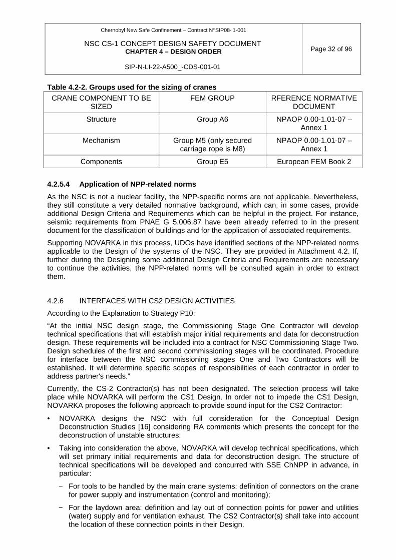
Table 4.2-2. Groups used for the sizing of cranes
CRANE COMPONENT TO BE SIZED
FEM GROUP RFERENCE NORMATIVE DOCUMENT
Structure Group A6 NPAOP 0.00-1.01-07 – Annex 1
Mechanism Group M5 (only secured carriage rope is M8)
NPAOP 0.00-1.01-07 – Annex 1
Components Group E5 European FEM Book 2
4.2.5.4 Application of NPP-related norms
As the NSC is not a nuclear facility, the NPP-specific norms are not applicable. Nevertheless, they still constitute a very detailed normative background, which can, in some cases, provide additional Design Criteria and Requirements which can be helpful in the project. For instance, seismic requirements from PNAE G 5.006.87 have been already referred to in the present document for the classification of buildings and for the application of associated requirements.
Supporting NOVARKA in this process, UDOs have identified sections of the NPP-related norms applicable to the Design of the systems of the NSC. They are provided in Attachment 4.2. If, further during the Designing some additional Design Criteria and Requirements are necessary to continue the activities, the NPP-related norms will be consulted again in order to extract them.
4.2.6 INTERFACES WITH CS2 DESIGN ACTIVITIES
According to the Explanation to Strategy P10:
“At the initial NSC design stage, the Commissioning Stage One Contractor will develop technical specifications that will establish major initial requirements and data for deconstruction design. These requirements will be included into a contract for NSC Commissioning Stage Two. Design schedules of the first and second commissioning stages will be coordinated. Procedure for interface between the NSC commissioning stages One and Two Contractors will be established. It will determine specific scopes of responsibilities of each contractor in order to address partner's needs.”
Currently, the CS-2 Contractor(s) has not been designated. The selection process will take place while NOVARKA will perform the CS1 Design. In order not to impede the CS1 Design, NOVARKA proposes the following approach to provide sound input for the CS2 Contractor:
• NOVARKA designs the NSC with full consideration for the Conceptual Design Deconstruction Studies [16] considering RA comments which presents the concept for the deconstruction of unstable structures;
• Taking into consideration the above, NOVARKA will develop technical specifications, which will set primary initial requirements and data for deconstruction design. The structure of technical specifications will be developed and concurred with SSE ChNPP in advance, in particular:
− For tools to be handled by the main crane systems: definition of connectors on the crane for power supply and instrumentation (control and monitoring);
− For the laydown area: definition and lay out of connection points for power and utilities (water) supply and for ventilation exhaust. The CS2 Contractor(s) shall take into account the location of these connection points in their Design.

Chernobyl New Safe Confinement – Contract N° SIP08- 1-001
NSC CS-1 CONCEPT DESIGN SAFETY DOCUMENT CHAPTER 4 – DESIGN ORDER
SIP-N-LI-22-A500_-CDS-001-01
Page 33 of 96
In order to facilitate the process, NOVARKA will remain at ChNPP’s disposal for possible coordination meetings with the CS2 Contractor(s). Requests for CS1 Design modification will be assessed by NOVARKA.
Chernobyl New Safe Confinement – Contract N° SIP08- 1-001
NSC CS-1 CONCEPT DESIGN SAFETY DOCUMENT CHAPTER 4 – DESIGN ORDER
SIP-N-LI-22-A500_-CDS-001-01
Page 34 of 96
4.3 METHODS AND MODELS USED FOR THE DESIGN
This section presents for information a list of the codes which have been used during the preliminary design stage (see Section 4.2). This list will be complemented by the calculation codes and models provided by the selected UDO. The final list of codes will be selected then and submitted for review if deemed necessary. In the framework of the Design, each calculation codes will be checked to ensure:
• that purpose, field and experience of application of the methods and models is applicable to the NSC project,
• the contents of the methods and models, including basic assumptions, admissions, restrictions comply with the NSC DCR,
• the addressed processes, impacts, mathematical methods used, models, software are applicable to the NSC project,
• the methods and models comply with the respective normative documents,
• the results are verifiable simply using, if needed, any additional code,
• the reliability and accuracy of the results.
Most of the codes here below are either of proven technology or in-house codes used for similar large-scale projects. As mentioned above, their characteristics are given for information.
4.3.1 FOUNDATIONS
This part deals with temporary foundations and permanent foundations.
• Foundations in erection and transportation zones:
1. Design phase:
♦ Design criteria for the temporary foundations
♦ Input soil data
♦ Design of piling system, ground beams and temporary supports; design principle is detailed hereafter
♦ Reinforcement principles.
2. Working Documentation phase:
• Working reinforcement drawings
• Foundations in service zone :
1. Design phase:
♦ Design Criteria for foundations.
♦ Input soil data
♦ Bearing capacity of pile
♦ Input data of reactions on supports
♦ Detailed design of piles, ground beams and west of walls supports; design principle is detailed hereafter
♦ Integration of the construction methodology
Chernobyl New Safe Confinement – Contract N° SIP08- 1-001
NSC CS-1 CONCEPT DESIGN SAFETY DOCUMENT CHAPTER 4 – DESIGN ORDER
SIP-N-LI-22-A500_-CDS-001-01
Page 35 of 96
♦ Reinforcement principles.
2. Working documentation phase:
♦ Working reinforcement drawings for piles.
♦ Workings reinforcement drawings for all foundations
• Soil structure interaction:
A complete 3D finite element model of soil structure interaction will be elaborated with SASSI software. It will take into account:
− the actual geometry and characteristics of piles (in erection and service zones) and ground beams
− the actual stratigraphy
− the static and dynamic properties of soil (viscoelastic behaviour).
This model will enable:
− with static soil characteristics:
♦ to take into account static group effect between piles, in erection and service zones
♦ to determine static impedances of piles (in erection and service zones), or ground beam (in transfer zone), which are obtained under null frequency solicitation,
♦ to determine static settlements and horizontal displacements in every zone
− with dynamic soil characteristics, in service zone:
♦ to take into account the dynamic group effect between piles
♦ to determine dynamic impedances of piles for different frequencies which correspond to the significant eigen frequencies of the arch
♦ to determine curves of solicitations in piles under unit dynamic forces and moments at pile top
• Foundation static calculations
erection and service areas:
Static calculations of the arch in erection and service area are performed with the 3D finite element model (refer to Section 4.3.2) which incorporates pile static impedance matrixes. This model enables to determine forces at bearing level under static elementary load cases.
Forces at bearing level under static elementary load cases will be applied to a 3D detailed finite model of ground beam and piles, using 3D finite element software ROBOT. In this model, ground beam is accurately modelled with shell elements of different thicknesses, and piles are modelled as beams with springs. This model enables to take into account the effect of differential stiffness in effort repartition between the piles and the ground beam. It enables to justify both longitudinal and transversal bending of the ground beam, and pile bending. The software will compute the forces in the member elements, the displacements and reactions, and will make the appropriate combinations.
The reinforced concrete sections will be justified with software SBAEL, according to EN 1992.
transfer area:
Static calculations of the arch in transfer area are performed with a 3D finite element model (refer to 4.3.2) which incorporates ground beam modelled as a beam, with static impedance matrixes which model the soil.
Chernobyl New Safe Confinement – Contract N° SIP08- 1-001
NSC CS-1 CONCEPT DESIGN SAFETY DOCUMENT CHAPTER 4 – DESIGN ORDER
SIP-N-LI-22-A500_-CDS-001-01
Page 36 of 96
Forces and displacements in the ground beam are calculated by the complete arch model.
The reinforced concrete sections will be justified with software SBAEL, according to EN 1992.
• Foundation dynamic calculations (service area):
Dynamic calculations of the arch in service area are spectral modal calculations performed with the 3D finite element model (refer to Section 4.3.2) which incorporates dynamic impedance matrixes for each individual pile. This model enables to determine forces in ground beam sections and at each pile top in each earthquake direction.
Forces under each earthquake direction in ground beam sections and at each pile top are combined with Newmark’s coefficients, and with relevant static load cases.
Efforts along piles are deducted from:
− efforts at pile top
− curves of solicitations in piles under unit dynamic forces and moments at pile top, obtained from SASSI model (see above)
The reinforced concrete sections will be justified with software SBAEL, according to EN 1992.
The other secondary elements (lateral protection walls) will be checked by separate calculations based on Eurocode Concrete and Concrete Structures Design EN 1992.
Software presentation:
− ROBOT: Structural finite element analysis software for dimensioning of the grounds beams and piles
− SBAEL: Reinforcement concrete section checks according to Eurocode EN 1992.
− SASSI 2000: finite element code developed by Berkeley University for Bechtel Co, which studies soil structure interaction, by calculating the displacement response to harmonic oscillations in frequency field. It enables to calculate stiffness and damping matrixes for the given frequency.
4.3.2 STEEL ARCH STRUCTURE
The main steel structure will be modelled as beam elements in the 3D finite element software HERGOS.
All loads calculated from the design criteria documents and other relevant standards will be automatically applied on this model and the software will compute the forces in the steel member elements, the displacements and reactions.
The calculations will be done with this same software in the construction and service configurations.
For this, complementary data are necessary for each element:
• buckling length;
• additional horizontal supports (reducing buckling length);
• steel grade.
The purlins and other secondary elements will be checked by separate calculations based on Eurocode EN 1993.
Chernobyl New Safe Confinement – Contract N° SIP08- 1-001
NSC CS-1 CONCEPT DESIGN SAFETY DOCUMENT CHAPTER 4 – DESIGN ORDER
SIP-N-LI-22-A500_-CDS-001-01
Page 37 of 96
The verifications of the steel elements to buckling (according to Eurocode EN 1993-1-1) are integrated in the calculation routines of the software.
Seismic calculations will be done with a modal spectral analysis, using spectra given in Chapter 2.
Stiffness and damping of the foundation (pile + soil) will be taken into account in the 3D model with dynamic impedance matrixes.
The floor response spectra at the overhead crane track girders will be derived from the seismic analysis by spectral transfer.
Software presentation: HERGOS:
• Purpose: Structural analysis software for dimensioning of the main steel structure;
• Validation: The core of this design package is the HERCULE software developed and validated by the checking company SOCOTEC;
• In house pre and postprocessors for load generation and sections checks;
• Inputs: Model geometry, nodes and elements, material and section characteristics, permanent and live load cases, combination charts;
• Results: element forces and stresses, displacements, reactions;
• Compliance with norms: Section checks according to Eurocode EN 1993.
Software presentation: SCAD
The 3D finite-element calculation model of the steel structure of the Arch will be represented by a set of core and plugins elements in StructureCAD (SCAD) program. The effect of the elastic flexibility of the foundation (piles and soil) will be taken into account by introducing the equivalent elastic support. For the consideration of the tension effect, changing during the assembly of the structure, both the calculation scheme and the “Assembly” mode will be used.
All the loads (constant, snow, wind, seismic etc.) are taken on the basis of design criteria, rule of choosing calculation combinations, which is used in SCAD program corresponds to DBN V.1.2-2: 2006, this choice is done automatically. Seismic calculations can be performed on the basis of spectral method according to DBN V.1.1-12: 2006 using the spectrum received for Chernobyl NPP site. Checking calculation is performed based on accelerograms, attached to DBN V.1.1-12: 2006.
SCAD Program is used to determine forces in the elements of steel structures and node points. This program is also used to evaluate the static stability and to determine the calculated length of each core element.
To check the main crane structure and other equipment the floor-by-floor accelerograms and response spectrums are built.
Strength and stability test of the steel structure elements for compliance with the requirements of SNiP II-23-81* will be performed with postprocessor “Bearing capacity test for steel structures” and CRYSTAL program, part of SCAD Office software system.
Presentation of SCAD Office
SCAD Office Software system consists of a number of independently working programs, connected through data exchange means. The system kernel is a universal finite-element calculative program StructureCAD (SCAD), besides that there is a series of satellite-programs:
• CRYSTAL – calculation of steel structure elements

Chernobyl New Safe Confinement – Contract N° SIP08- 1-001
NSC CS-1 CONCEPT DESIGN SAFETY DOCUMENT CHAPTER 4 – DESIGN ORDER
SIP-N-LI-22-A500_-CDS-001-01
Page 38 of 96
• ARBAT – reinforcement selection and expert analyses of reinforcement structure elements
• KAMIN – calculation of stone structures and reinforcement masonry;
• DECOR - calculation of wooden structures;
• ZAPROS – calculation of base and foundation elements;
• OTKOS – stability test for slopes;
• VEST – weight calculation according to SNiP "Loads and impacts" and DBN;
• COMET, CОМЕТ-2 – calculation and design of steel structure joints;
• CROSS – calculation of coefficients for building and facility beds and constructions on elastic foundation;
• SECTION DESIGNER – formation and calculation of geometric properties of rolled sections and sheets;
• CONSUL – building random sections and calculation of their geometric properties on the base of the “solid bar theory”;
• TONUS - building random sections and calculation of their geometric properties on the base of the “thin-walled bar theory”.
SCAD Office is certified in accordance with GOST R ISO/MEC 9126-93, GOST 28195-89, GOST R ISO 9127-94, RD 50-34.698-90.
SCAD possesses single graphical environment for calculative scheme synthesis and analyses of the results, which ensures possibilities to simulate calculative schemes from the simplest to the most complex structures.
High production processor allows solve tasks of high dimensionality (hundreds of thousands of degrees of freedom with static and dynamic loads).
SCAD includes a developed library of finite elements for simulating bar, elastic, solid body, and combined structures, modules of stability analyses, forming calculative loads combinations, checking work strain of structure elements with various strength theories, determining interaction forces of the fragment with the structure, calculation of forces and displacements through load combinations. The complex also includes software for reinforcement selection in concrete-steel structures and checking element sections of metal structure.
SCAD working results are graphically represented values of displacements in joints, as well as iso-fields and iso-lines of displacements for tabular and volume elements; forces in axial elements, represented as distribution diagrams for the whole scheme or a separate element, and color-coded indication of maximum values of the selected force factor; forces and stresses in tabular and volume elements, which are represented as iso-fields and iso-lines in the selected range of color scale with the possibility of simultaneous representation of numerical values. The calculation results in tables can be exported into MS Word or MS Excel spreadsheets.
The compliance with SNiP is confirmed by certificates of Gosstandart of Russia and Federal agency of Russia in nuclear and radiation safety. The intergovernmental agreement between Ukraine and Russia on mutual acknowledgement of the certificates allows using the above mentioned certificates while designing Ukrainian facilities.
SCAD allows importing data from a number of finite-element and graphical systems, including SW HERGOS.
Crystal Program is intended for testing elements and joints of steel structures for compliance with the requirements of SNiP II-23-81* "Steel structures. Design norms". Besides that during the development of the program state standards connected with SNiP II-23-81* were used,
Chernobyl New Safe Confinement – Contract N° SIP08- 1-001
NSC CS-1 CONCEPT DESIGN SAFETY DOCUMENT CHAPTER 4 – DESIGN ORDER
SIP-N-LI-22-A500_-CDS-001-01
Page 39 of 96
"Steel structures design manual (to SNiP II-23-81*) / ZNIISK named after Kucherenko" and some methodological provisions of the prepared but not yet brought into force new draft norms for SNiP 53-1-96 " Steel structures. Design norms" and "General rules of design of steel structure elements and joints (SP 53-101-96)".
The compliance with SNiP is confirmed by the certificate of Gosstandart of Russia.
.
Figure 4.3-1. SCAD soft. Certificate of Conformity
Chernobyl New Safe Confinement – Contract N° SIP08- 1-001
NSC CS-1 CONCEPT DESIGN SAFETY DOCUMENT CHAPTER 4 – DESIGN ORDER
SIP-N-LI-22-A500_-CDS-001-01
Page 40 of 96
4.3.2.1 Fire resistance stability of the steel stru cture:
The fire resistance stability of the steel structure will be carried according to specific scenarios based on the fire loads of the existing buildings of unit 4 and truck fires located at the entrance of the arch shelter.
The calculations shall be implemented in two steps:
• Fire growth within the NSC with the FDS software
• Structural stability with LENAS, ANSYS or SAFIR software.
The forces and stresses generated in the steel elements will be combined with the other load effects according to Eurocode standard EN 1993.
Software presentation: FDS: 3-D model Fire Dynamics Simulator (FDS) – Version 4.2
• Purpose : Fire dynamics calculations;
• Validation: NIST: National Institute of Standards, US Dept. Of Commerce;
• In house developments on fuel mass loss and consummation;
• Inputs: Geometry of the arch and internal volumes, fire load and characteristics;
• Results : Temperature fields and fluxes in the inner volume and steel structural elements;
• Compliance with norms : Eurocode EN 1991-1- 2;
• Accuracy: Enhanced by in house developments.
Software presentation: LENAS
• Purpose: Structural Analysis at high temperature (Large Elasto-Plastic Numerical Analysis of Structures-Member in Transient State);
• Validation: In House – Report INC-98/171-GF/IM May 1998;
• Inputs: Geometry, Loads, Material;
• Results : Deflection and displacement of the structures at high temperature;
• Compliance with norms : Eurocode EN 1993-1- 2;
• Accuracy: Validation on scaled model.
Software presentation: SAFIR
• Purpose: Structural Analysis at high temperature;
• Validation: University of Liège – Belgium;
• Inputs: Temperature fields and fluxes from FDS analysis;
• Results: deflection and displacement of structures at high temperature;
• Compliance with norms : Eurocode EN 1993-1- 2;
• Accuracy: Validation on scaled model.
Software presentation: ANSYS
• Purpose: Structural Analysis at high temperature;
• Validation: Ansys Inc.;
• Inputs: Temperature fields and fluxes from FDS analysis;
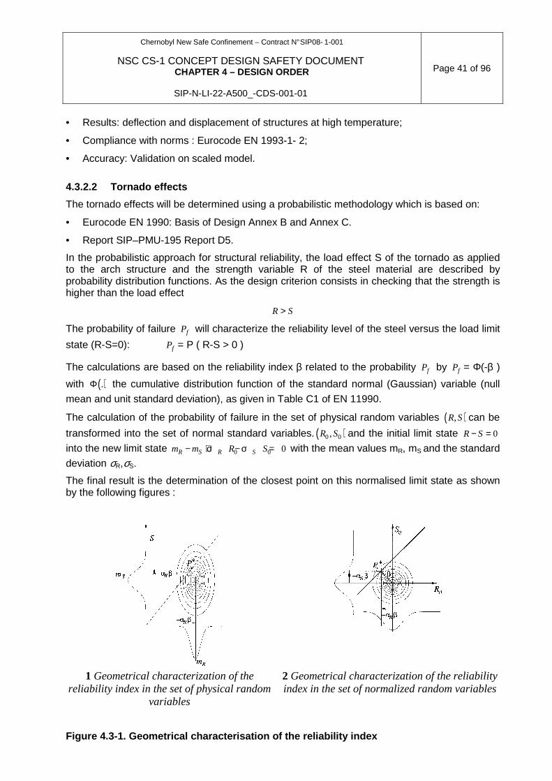
Chernobyl New Safe Confinement – Contract N° SIP08- 1-001
NSC CS-1 CONCEPT DESIGN SAFETY DOCUMENT CHAPTER 4 – DESIGN ORDER
SIP-N-LI-22-A500_-CDS-001-01
Page 41 of 96
• Results: deflection and displacement of structures at high temperature;
• Compliance with norms : Eurocode EN 1993-1- 2;
• Accuracy: Validation on scaled model.
4.3.2.2 Tornado effects
The tornado effects will be determined using a probabilistic methodology which is based on:
• Eurocode EN 1990: Basis of Design Annex B and Annex C.
• Report SIP–PMU-195 Report D5.
In the probabilistic approach for structural reliability, the load effect S of the tornado as applied to the arch structure and the strength variable R of the steel material are described by probability distribution functions. As the design criterion consists in checking that the strength is higher than the load effect
R S>
The probability of failure fP will characterize the reliability level of the steel versus the load limit
state (R-S=0): fP = P ( R-S > 0 )
The calculations are based on the reliability index β related to the probability fP by fP = Φ(-β )
with ( ).Φ the cumulative distribution function of the standard normal (Gaussian) variable (null
mean and unit standard deviation), as given in Table C1 of EN 11990.
The calculation of the probability of failure in the set of physical random variables ( ),R S can be
transformed into the set of normal standard variables. ( )0 0,R S and the initial limit state 0R S− =
into the new limit state 0 0 0R S R Sm m R S− + σ − σ = with the mean values mR, mS and the standard
deviation σR,σS.
The final result is the determination of the closest point on this normalised limit state as shown by the following figures :
1 Geometrical characterization of the reliability index in the set of physical random
variables
2 Geometrical characterization of the reliability index in the set of normalized random variables
Figure 4.3-1. Geometrical characterisation of the r eliability index
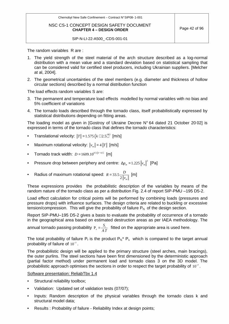
Chernobyl New Safe Confinement – Contract N° SIP08- 1-001
NSC CS-1 CONCEPT DESIGN SAFETY DOCUMENT CHAPTER 4 – DESIGN ORDER
SIP-N-LI-22-A500_-CDS-001-01
Page 42 of 96
The random variables R are :
1. The yield strength of the steel material of the arch structure described as a log-normal distribution with a mean value and a standard deviation based on statistical sampling that can be considered valid for certified steel producers, including Ukrainian suppliers. [Melcher at al, 2004].
2. The geometrical uncertainties of the steel members (e.g. diameter and thickness of hollow circular sections) described by a normal distribution function
The load effects random variables S are:
3. The permanent and temperature load effects modelled by normal variables with no bias and 5% coefficient of variations
4. The tornado loads described through the tornado class, itself probabilistically expressed by statistical distributions depending on fitting areas.
The loading model as given in [Gostroy of Ukraine Decree N° 64 dated 21 October 20 02] is expressed in terms of the tornado class that defines the tornado characteristics:
• Translational velocity: ( )1.51.575 2.5T k= + [m/s]
• Maximum rotational velocity: 4mv T= [m/s]
• Tornado track width: ( )0.5 4.51609.10 kD −= [m]
• Pressure drop between periphery and centre: 2
1.225m mp v∆ = [Pa]
• Radius of maximum rotational speed: 33.52 m
DR
v= [m]
These expressions provides the probabilistic description of the variables by means of the random nature of the tornado class as per a distribution Fig. 2.4 of report SIP-PMU –195 D5-2.
Load effect calculation for critical points will be performed by combining loads (pressures and pressure drops) with influence surfaces. The design criteria are related to buckling or excessive tension/compression. This will give the probability of failure Pf1 of the design section.
Report SIP-PMU–195 D5-2 gives a basis to evaluate the probability of occurrence of a tornado in the geographical area based on estimated destruction areas as per IAEA methodology. The
annual tornado passing probability ts
S
A T=P fitted on the appropriate area is used here.
The total probability of failure Pf is the product Pf1* Ps which is compared to the target annual probability of failure of 710− .
The probabilistic design will be applied to the primary structure (steel arches, main bracings), the outer purlins. The steel sections have been first dimensioned by the deterministic approach (partial factor method) under permanent load and tornado class 3 on the 3D model. The probabilistic approach optimises the sections in order to respect the target probability of 710− .
Software presentation: ReliabTbx 1.4
• Structural reliability toolbox;
• Validation: Updated set of validation tests (07/07);
• Inputs: Random description of the physical variables through the tornado class k and structural model data;
• Results : Probability of failure - Reliability Index at design points;

Chernobyl New Safe Confinement – Contract N° SIP08- 1-001
NSC CS-1 CONCEPT DESIGN SAFETY DOCUMENT CHAPTER 4 – DESIGN ORDER
SIP-N-LI-22-A500_-CDS-001-01
Page 43 of 96
• Compliance with norms: Eurocode EN 1990.
4.3.3 CLADDING/ROOFING
The corrugated metal decking will be checked according to EN 1993-1-3 “Design of steel structure – Part 1.3: General rules – Supplementary rules for cold-formed members and sheeting”.
External and internal stainless steel or aluminium membranes will be checked using Finite element analysis running either elastic analysis or plastic analysis. Results will be confirmed by the test on the panel.
Software to be used will be ANSYS or similar.
When no recognized method exists for calculation of an item then a specific test will be performed to confirm the performance of the designed item.
Connecting fasteners will be checked in this way.
4.3.4 MAIN CRANE SYSTEM
The calculation in nominal mode of the main cranes system Drives, Gears, Girder sizing, carriages, and Shafting will be made according to the FEM rules. These calculations are based on the methods and principles of Strength of Materials.
The kinematic analysis and the power distribution analysis are also part of the nominal mode.
Finite element analyses will also be performed to analyze deflections of different mast cross section shapes and material thicknesses, and stresses under the telescopic mast pads further to the results of the linear Static analysis of the Shell Meshed surface model.
Some particular operating sequences as carriage transfer from one quadrilateral to another will be subject to a specific and detailed calculation note. Also for this note, the Strength of Materials methods and principles will be applied.
A specific analysis will be made for the beam rotation using 2 carriages.
Also some additional calculation notes will be performed in layered mode: These calculation notes will come from the risk analysis results to identify the cases which are going to size the main cranes system.
It is assumed that the following events will be subject to the dedicated calculation note:
• Earthquake: To verify that no drop load will occur in case of DBE, and that the carriage and the quadrilateral will not fall down in case of MDE;
• Collision between the Mobile Platform Lift Tool and an obstacle: To verify that the Mobile Lift Platform tool will not be destroyed;
• For the classic and specific carriage, the demonstration that the second cable will withstand the load in case of failure of the first cable will be carried out.
This list is non exhaustive and will be updated according to the risk assessment results.
4.3.5 VENTILATION
Thermal performance of the arch (confined space and annular space) is simulated by Computational Fluid Dynamics (CFD) software.
This software is AIRPAK, a product of ANSYS Inc. Corporate.

Chernobyl New Safe Confinement – Contract N° SIP08- 1-001
NSC CS-1 CONCEPT DESIGN SAFETY DOCUMENT CHAPTER 4 – DESIGN ORDER
SIP-N-LI-22-A500_-CDS-001-01
Page 44 of 96
ANSYS designs, develops, markets and globally supports engineering simulation solutions used to predict how product designs will behave in manufacturing and real-world environments.
The design analysis software of this firm is the first to be created within a quality system with ISO 9001 certification, the internationally accepted quality standard.
The product development, testing, maintenance and support processes also meet the USA Nuclear Regulatory Commission’s quality requirements.
AIRPAK is virtual prototyping software that enables to accurately and easily model airflow, heat transfer, contaminant transport and thermal comfort in ventilation systems.
AIRPAK CFD software models the airflow induced by AHU’s and networks of ducts in the annular and confined spaces.
Thermal comfort and indoor air quality are the primary objectives of these HVAC systems.
CFD models are constructed to accurately predict the local ambient conditions (air velocity, radiant temperature, relative humidity).
These results, coupled with information on external and internal conditions, are then assessed against comfort criteria.
Workers safety can also be affected by the presence of airborne pollutants. If a source of pollutants is present nearby, then AIRPAK CFD software can also assess the impact of these pollutants.
The results of thermal performance of the arch (temperatures only) permit:
• To size equipment (Air Handling Units [AHUs], fans) on basis of winter design criteria’s (heating power, extreme and design conditions) with optimization of the systems (airflows, temperatures);
• To study during the second stage the potential of condensation within the confined space and the annular space;
• These studies are based on:
• Analysis of climatic data on the site;
• Risk analysis of condensation phenomenal from diagram of Mollier.
4.3.6 RADIATION PROTECTION
The method to assess, at the design stage, the effective external and internal exposure doses uses the ChNPP procedure agreed by the Ministry of Health in 2004 (Procedure of Calculating the Personnel Current and Potential Exposure Doses in Planning and Design of Works at the Shelter). When radiation data measurements are not available to develop radiological protection and hygienic recommendations (for instance in case of change in radiological conditions during work performance, of change in γ-radiation dose field following shielding installation, etc...), some specific calculation models could be used to estimate external exposure doses and radioactive airborne concentration after release. The compliance of these models with methodologies agreed with the Ministry of Health of Ukraine shall be justified.
Chernobyl New Safe Confinement – Contract N° SIP08- 1-001
NSC CS-1 CONCEPT DESIGN SAFETY DOCUMENT CHAPTER 4 – DESIGN ORDER
SIP-N-LI-22-A500_-CDS-001-01
Page 45 of 96
4.4 TESTING DURING THE DESIGN PROCESS
Present section provides brief information on the important tests (planned during designing) for components of NSC basic protective structure. At early design stages, detailed testing programs will be developed and provided within design packages. The need for realization of other tests will be defined during designing.
4.4.1 TEST OF CORROSIVITY
In addition to the NIISK investigation (“Investigation of the metal corrosion speed for the building structures of the Shelter” Report on research work, refer to extract in Section 3.9.1), NOVARKA will perform an additional test of corrosiveness according to ISO standard.
4.4.1.1 Presentation of the test
The test will be performed during the period of one year as per ISO 9225 and ISO 9226 using small cabinets (approximately 600*500*300mm) fixed close to the fence surrounding the CHNPP unit 4 area.
These cabinets will be equipped with test plates, measuring devices and sensors.
The test consists in measuring every three months during the period of one year the following information:
• The loss of material on representative samples of different types of material;
• The temperature, % of relative humidity on a basis of continuous recording (one measure every 15min);
• The chemical composition and pollution of the atmosphere.
4.4.1.2 Execution of the test
The test to be implemented and equipment to be used are prepared by a corrosion expert who will install the cabinets, attend the first survey and train the staff that will perform the next surveys. There will be four surveys at three, six, nine and twelve months.
After each survey analysis of the results and interim assessment of the class of corrosiveness will be performed by the corrosion expert. After the third survey (at 9 months) it will be reasonably assumed to have enough information to select the material. The last survey will confirm this assumption.
4.4.1.3 Reports
There will be 3 interim reports and one final report prepared by the corrosion expert. The final report will include the expert recommendation for selection of adequate materials.
4.4.1.4 Roof panel tests
The roof panel will be tested in laboratory. The aim of this test is to validate the design stage to ensure the resistance of the compound under loads orthogonal to the panel (dead load, snow and service loads, wind and tornado 1.5 and 3) and to evaluate its air permeability.
The dimensions of the panel and bearing condition will be representative of the behaviour of the final one.
Chernobyl New Safe Confinement – Contract N° SIP08- 1-001
NSC CS-1 CONCEPT DESIGN SAFETY DOCUMENT CHAPTER 4 – DESIGN ORDER
SIP-N-LI-22-A500_-CDS-001-01
Page 46 of 96
During the test, elastic (reversible) deformation at SLS stage as well as permanent deformation (under tornado class 3) will be measured. Locking performance of the lock seam of the external membrane on the halters (if any) will be checked.
After checking the behaviour of the panel under the different loading combinations the test will be extended up to the destruction of the panel or one of the components.
The Contractor will prepare test protocol and test report.
The test will be performed at the second phase of the Design after the choice of the solution by the Employer.
4.4.2 WIND TUNNEL TEST
4.4.2.1 Introduction
Wind tunnel tests determine the most unfavourable wind actions effects on the different elements of the steel structure and its supports, the cladding-roofing skins have been carried by the CSTB laboratory in Nantes, France.
The actual aerodynamic environment and roughness of the site, the main surrounding buildings have been duly reproduced in the wind tunnel.
Tests have been carried for the final configuration and for different construction phases. For each configuration, measurements have been done for 36 wind directions (every 10 degrees).
The model is equipped with a significant number of pressure measurement points in order to obtain representative maps of instantaneous wind pressure.
The positions of these measurement points have been chosen in relation with the steel structure model according to the position of the steel supporting members.
Influence coefficients provided by the steel structure design office were used by CSTB to calculate the simultaneous pressure cartographies extracted from the tests, the maximum and minimum value for each specified global force or displacement and edit the corresponding complete cartographies of pressure.
The boundary layer tunnel is 4 m wide, 2.5 m high and 15 m long. The test section is adapted to various roughness; for the NSC, roughness type 3 of Eurocode EN 1991-1-4 has been selected (sub urban or industrial areas and permanent forests)
The model is equipped with 512 pressure tap sensors distributed mainly on the inner and outer envelope of the arch truss structure. Some sensors are located on the west and east walls.
The cartographies of pressure are calculated from the test results by specialised in-house software of signal treatment developed by CSTB laboratory.
These selected cartographies will serve after analysis as the base for the input data of wind actions on the structural model.
These tests started at the end of April 2008. Results (pressure fields) are available since the end of June 2008 as input for the modelling of the wind actions in the 3D model of the steel arch.
4.4.2.2 Wind test methodology
The wind in the lower layers of the atmosphere is naturally turbulent, that is to say it fluctuates in both speed and direction at all points in a given space. In the case of the proposed very large Shelter structure project set on unit 4 of the Chernobyl nuclear power plant, this natural turbulence can be emphasised in the case of certain wind directions by the disturbing effect of
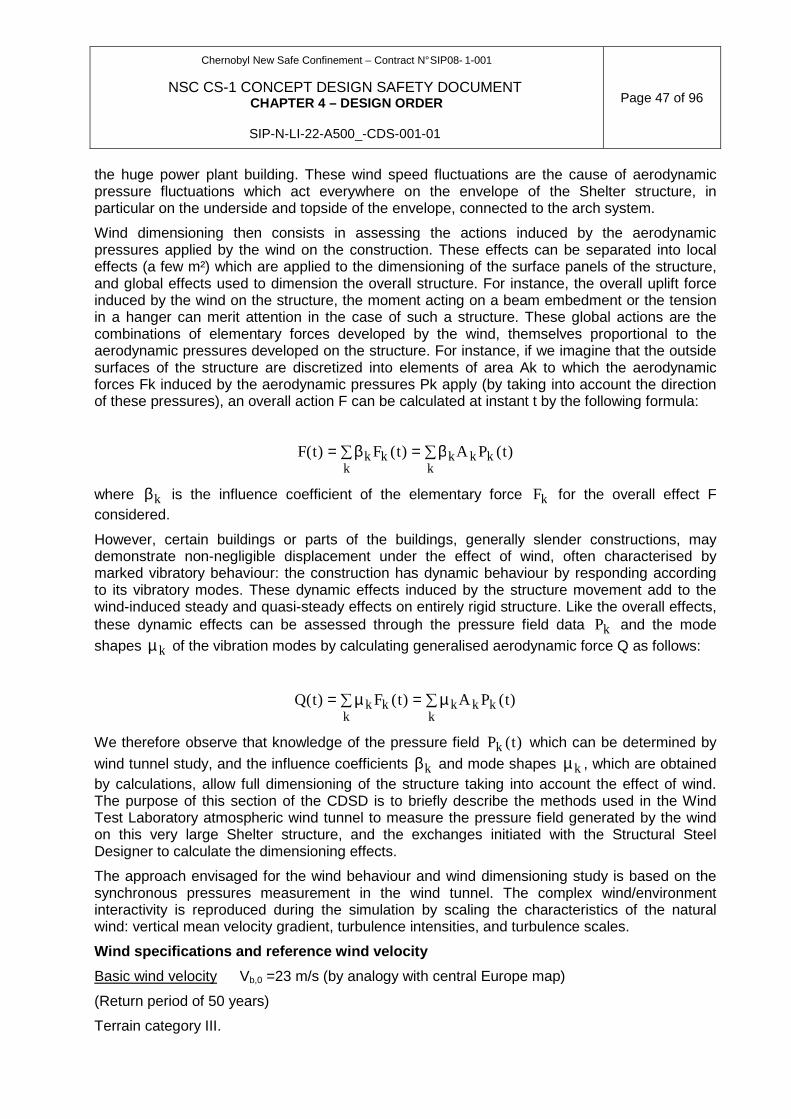
Chernobyl New Safe Confinement – Contract N° SIP08- 1-001
NSC CS-1 CONCEPT DESIGN SAFETY DOCUMENT CHAPTER 4 – DESIGN ORDER
SIP-N-LI-22-A500_-CDS-001-01
Page 47 of 96
the huge power plant building. These wind speed fluctuations are the cause of aerodynamic pressure fluctuations which act everywhere on the envelope of the Shelter structure, in particular on the underside and topside of the envelope, connected to the arch system.
Wind dimensioning then consists in assessing the actions induced by the aerodynamic pressures applied by the wind on the construction. These effects can be separated into local effects (a few m²) which are applied to the dimensioning of the surface panels of the structure, and global effects used to dimension the overall structure. For instance, the overall uplift force induced by the wind on the structure, the moment acting on a beam embedment or the tension in a hanger can merit attention in the case of such a structure. These global actions are the combinations of elementary forces developed by the wind, themselves proportional to the aerodynamic pressures developed on the structure. For instance, if we imagine that the outside surfaces of the structure are discretized into elements of area Ak to which the aerodynamic forces Fk induced by the aerodynamic pressures Pk apply (by taking into account the direction of these pressures), an overall action F can be calculated at instant t by the following formula:
F t F t A P tk k k k kkk
( ) ( ) ( )= = ∑∑β β
where βk is the influence coefficient of the elementary force Fk for the overall effect F considered.
However, certain buildings or parts of the buildings, generally slender constructions, may demonstrate non-negligible displacement under the effect of wind, often characterised by marked vibratory behaviour: the construction has dynamic behaviour by responding according to its vibratory modes. These dynamic effects induced by the structure movement add to the wind-induced steady and quasi-steady effects on entirely rigid structure. Like the overall effects, these dynamic effects can be assessed through the pressure field data Pk and the mode
shapes µ k of the vibration modes by calculating generalised aerodynamic force Q as follows:
Q t F t A P tk k k k kkk
( ) ( ) ( )= = ∑∑µ µ
We therefore observe that knowledge of the pressure field P tk ( ) which can be determined by
wind tunnel study, and the influence coefficients βk and mode shapes µ k , which are obtained by calculations, allow full dimensioning of the structure taking into account the effect of wind. The purpose of this section of the CDSD is to briefly describe the methods used in the Wind Test Laboratory atmospheric wind tunnel to measure the pressure field generated by the wind on this very large Shelter structure, and the exchanges initiated with the Structural Steel Designer to calculate the dimensioning effects.
The approach envisaged for the wind behaviour and wind dimensioning study is based on the synchronous pressures measurement in the wind tunnel. The complex wind/environment interactivity is reproduced during the simulation by scaling the characteristics of the natural wind: vertical mean velocity gradient, turbulence intensities, and turbulence scales.
Wind specifications and reference wind velocity
Basic wind velocity Vb,0 =23 m/s (by analogy with central Europe map)
(Return period of 50 years)
Terrain category III.
Chernobyl New Safe Confinement – Contract N° SIP08- 1-001
NSC CS-1 CONCEPT DESIGN SAFETY DOCUMENT CHAPTER 4 – DESIGN ORDER
SIP-N-LI-22-A500_-CDS-001-01
Page 48 of 96
Scale of the model and wind simulation
In view of the dimensions of this very large structure and of the wind tunnel cross section, the simulation scale adopted is 1:300. Consequently, the model is constructed to this scale and wind equivalent to class III of the site is simulated using roughness distributed on the floor of the wind tunnel upstream of the arch structure model. Immediate surroundings similar to the one close to the site (Power plant buildings) complete the set-up.
Construction of the Arch Model and the surrounding model
The 1/300 model of the structure is constructed in moulded Plexiglas, it reproduces accurately its geometry, the outer and the inner envelope and the arch truss set inside. The model is fitted with about 500 pressure taps distributed mainly on transversal cross sections of the structure, complemented by additional taps on the lateral walls. These pressure taps are connected, using vinyl tubes, to high-performance multiplexed sensors set under the wind tunnel floor.
The more refined distribution is used near the edges or singular elements where the worst loadings are expected. The instrumentation on the two sides of the roofing in homologous locations allows estimates of the net aerodynamic pressure acting on these elements. The definition of all this instrumentation is defined in close collaboration with Structural Steel Designer.
This methodology allows the characterisation of the peak loadings (max positive pressures and min suction pressures) on local areas (~1m²) and provides the necessary information to compute the whole loading on the roofing and on the fasteners of the structure.
Additional instrumentation using 6 component dynamometric balance completes the pressure measuring system. The balance is located under the wind tunnel floor and is connected to the arch model via the supporting rails. It allows the calibration of the pressure integrations and fine-tuning of the horizontal forces exerted by the wind.
The surroundings of the structure are reproduced on ~ 500m radius, including all the buildings or structures likely to interact from the aerodynamic point of view.
Test configurations
According to wind tunnel test specifications, several configurations (Construction configurations and the final Phase) of the structure are successively tested.
The wind tunnel study is executed for all wind directions (36 wind directions in 10° steps) and for each arch configuration.
4.4.2.3 Dimensioning load evaluation
The technique of measuring synchronous pressures generates instantaneous picture of load distribution on the envelope of the structure, the distribution which is digitalized in real time by the wind tunnel acquisition chain. As described previously, we thereby determine the local loads per m² necessary to dimension the covering panels and their attachments, and the overall loads used for overall dimensioning by appropriate combination of measured pressures.
Local loads
Processing the measured pressures, the maximum, minimum and differential loads are calculated for all wind directions. The differential loads can represent either difference between the upper side and the underside of the Shelter, or difference between the external pressure at
Chernobyl New Safe Confinement – Contract N° SIP08- 1-001
NSC CS-1 CONCEPT DESIGN SAFETY DOCUMENT CHAPTER 4 – DESIGN ORDER
SIP-N-LI-22-A500_-CDS-001-01
Page 49 of 96
the surface and the internal pressure acting on the opposite surface. This internal pressure is measured by specific sensor set between the external and the internal sheath of the structure.
Statistical analysis of the measurements allows extracting the maximum and minimum worst loading, all wind directions included. The results are delivered in graphical representation and Excel files.
Overall loads
This part of the study consists in determining semi global and global loads acting on the structure, i.e. the time histories of the bending and torsion base moments, the lift and the shear forces, and other deformations defined in close collaboration with the project's representatives. In association with the Structural Steel Designer, twenty or so deformations are calculated. The Structural Steel Designer supplies the influence coefficients associated with the specific deformations having integrated the individual surfaces to which they refer in them.
The final results will be pressure fields concomitant with the dimensioning deformations, deformations obtained after statistical treatment of the timed histories of the calculated deformations. These pressure fields are used by the Structural Steel Designer as load case inputs for finite element calculations.
4.4.3 PILE TEST
Pile Test for construction methodology:
Pile test will be performed to check the construction methodology with procedure developed specifically for the project to limit worker radiological exposure.
Determination of equivalent static pile bearing cap acity by dynamic load test:
NOVARKA propose to check the pile bearing capacity by performing dynamic load test described as follows:
• The pile dynamic test was created in France about 25 years ago. Such test, performed according to French Norm XP-P-94-152 or European Standard in Project No: Pr EN ISO 22477-1-4, gives charge/displacement curve similar to the curve that could have been obtained with static load test.
• Dynamic load test consists in performing a series of shocks of various energy, after placing instrumentation at the pile top consisting of accelerometers, strains gauges and theodolite target. For each blow, signal treatment is carried out in order to obtain at first the dynamic resistance and, after laboratory calculations, the equivalent static bearing capacity.
This method has known many evolutions and it has been shown that perfect quality of the collected dynamic signals is necessary in order to proceed to perfect signal treatment and hence, access to good approach of the equivalent static bearing capacity.
The test can be carried out either on concrete bored piles or on steel driven ones. In some cases, when all the soil properties are well known, the value of shaft resistance (skin friction) and point resistance at toe can be determined by numerical simulation coupled with the data collected during the dynamic test.
Piles Integrity:
After pile construction, acoustic test on no less than 10% of the piles will be performed to check the concrete pile integrity.

Chernobyl New Safe Confinement – Contract N° SIP08- 1-001
NSC CS-1 CONCEPT DESIGN SAFETY DOCUMENT CHAPTER 4 – DESIGN ORDER
SIP-N-LI-22-A500_-CDS-001-01
Page 50 of 96
4.4.4 SOIL INVESTIGATION
Complementary soil investigation (CPTs + Pressuremeter, according EN 1997-2: 2007 -Part 2) in the temporary and service areas will be performed to confirm the soil characteristics given in the Contract.
The purpose of this site investigation is to verify the soil criteria given in the Soil Analysis Report and to extend the investigations under the foundation beams to obtain valuable data for the design.
The soil investigation will be performed in two stages. Detail information reflect in section 3.9.2.
Chernobyl New Safe Confinement – Contract N° SIP08- 1-001
NSC CS-1 CONCEPT DESIGN SAFETY DOCUMENT CHAPTER 4 – DESIGN ORDER
SIP-N-LI-22-A500_-CDS-001-01
Page 51 of 96
4.5 QUALITY ASSURANCE DURING DESIGN
4.5.1 INTRODUCTORY STATEMENT
This section describes NOVARKA’s Detailed Design process and information is extracted from SIP-N-MS-22-A30--MAN-001, Integrated Management Systems Manual and daughter document SIP-N-TM-22-B-MPL-001, Designing Plan.
4.5.2 MANAGEMENT SYSTEM BASIS
Contract - SIP08-1-001, New Safe Confinement Design, Construction And Commissioning
Contract Condition 4.9 specifies:
“QMS documents shall be based on and comply with ISO 9001:2000 and ISO-10005: 2005. In addition, application of the concepts and recommendations contained in “Quality Standards: Comparison Between IAEA 50-C/SG-Q and ISO 9001:2000” (IAEA Safety Report Series No.22) Sections 5.1 and 5.2 shall be included in QMS documents.”
The relevant revision of ISO-10005: 2005 is taken as a basis for the design.
4.5.3 REFERENCE DOCUMENT REVIEW
In order to establish the full scope of quality assurance requirements, review of applicable Norms and Standards identified further baseline documents to be considered for the designing process.
Chernobyl New Safe Confinement – Contract N° SIP08- 1-001
NSC CS-1 CONCEPT DESIGN SAFETY DOCUMENT CHAPTER 4 – DESIGN ORDER
SIP-N-LI-22-A500_-CDS-001-01
Page 52 of 96
Table 4.5-1. Baseline documents to be considered fo r the Designing process Coding Documents
CMU Decree No. 421 Procedure for Realization of the Shelter Implementation Plan
CMU Decree No. 1243 Procedure for acceptance of facilities constructed
Contract - SIP08-1-001 New Safe Confinement Design, Construction and Commissioning and attachments
Contract Att. 00 Description of Engineering Requirements
Contract Att. 03 SIP-P-ТM-21-330-DC-101-01
NSC Design Criteria and Requirements
Contract Att. 14 Licensing Plan For NSC Project Realization
SIP-P-PM-22-046-SOW- 052-010 Scope of Work
SIP-P-SR-21-330-REC-117-02 Structure And Requirements To Contents Of The NSC CS-1 Concept Design Safety Document
DBN A.2.2-3-04 Design. Content, procedure for development, concurrence and approval of design documents for construction
DSTU B.A.2.4-4-99 The Basic Requirements to the Design and Working Documentation
DBN A.3.1-5-96 Organisation of the construction process
NRBU-97 Norms for Radiation Safety of Ukraine, 1997
SIP-N-TM-22-B-MPL-001 Designing Plan
4.5.4 DOCUMENTATION OF THE OVERALL MANAGEMENT SYSTEM
Based on the above requirements SIP-N-MS-22-A30--MAN-001, Integrated Management Systems Manual (IMSM) was developed to encapsulate these requirements and specifically identify how NOVARKA quality management systems interface with the Joint Venture Partners, SIP-PMU, SSE ChNPP and supplier quality management systems.
The IMSM contains NOVARKA’s policy statement and descriptions of the integrated management system, processes and supporting information. It specifically defines the Design and Technical process elements and also identifies which Contract deliverables are applicable to the designing process.
The organisation structure and job descriptions that indicate how the management system is to be applied is presented in SIP N MS 22 DM__-MPR 001, Organization Chart & Job Descriptions. The brief information from these documents is provided below.
DETAILED DESIGN MANAGEMENT SYSTEM
The general designing process requirements within IMSM were further elaborated in Designing Plan, which identifies the lower process interactions between the various NOVARKA departments and immediate stakeholders.
The purpose and scope of Designing Plan are as follows:
• To describe NOVARKA’s interpretation of the Contractual requirements to satisfy the designing activities of the Detailed Design stage of the New Safe Confinement
Chernobyl New Safe Confinement – Contract N° SIP08- 1-001
NSC CS-1 CONCEPT DESIGN SAFETY DOCUMENT CHAPTER 4 – DESIGN ORDER
SIP-N-LI-22-A500_-CDS-001-01
Page 53 of 96
Commissioning Stage 1. It contains an evolutionary description of the process, an organisation structure, job descriptions, interface definition and directional guidance. Future stages will be elaborated as the Project progresses;
• To establish the requirements which define the elements of designing to ensure nuclear and radiological safety and by inference, the safe operation of the New Safe Confinement. These requirements are applicable to safety functions and associated structures, system and components (SSC) as well as to SSC documentation important to safety (IS);
• To establish the requirements for SSC not important to safety (NIS) that must be met to enable the process operation of the New Safe Confinement within the confines of occupational and industrial safety standards.
Also included are the outputs required for safety assessment and licensing of SSC-IS and the development of Working Designs prior to the construction phase.
Designing Plan contains:
1. description of the Detailed Design Management System;
2. The Designing Core Team organisation and interrelationships with interested parties;
3. Job Descriptions indicating responsibility and authority;
4. Descriptions of the processes and supporting information required to affect the designing process.
Designing Plan is updated during the various stages of Project development.
4.5.5 GRADING THE REQUIREMENTS APPLIED TO MANAGEMENT SYSTEM
In order to allow the deployment of appropriate resources, the Detailed Design process has been developed to follow the requirements of normative documents considering the IAEA recommendations as follows:
1. International Atomic Energy Agency GS-R-3, The Management System for Facilities and Activities for SSC-IS;
2. International Organisation of Standardisation (ISO) 9001-2000, Quality management systems (DSTU 9001-2001) for SSC-NIS.
4.5.6 SATISFACTION OF INTERESTED PARTIES
In order to ensure that the Employer and Ukrainian Regulatory Authorities achieve timely and satisfactory conclusions to relevant design and safety issues, regular interface and technical meeting are held and minutes of meeting generated.
4.5.7 ORGANISATIONAL POLICIES FOR QUALITY, SAFETY, ETC.
NOVARKA’s Management Mission and Policy Statement follows the requirements which call for an integrated management system based on safety, which includes quality management; it states:
PROJECT MISSION STATEMENT NOVARKA has only one mission and that is to comply with Contract Agreement SIP08-1-001 and all Amendments signed on the 8th August 2007 and issued by the Employer, State Special Enterprise Chernobyl Nuclear Power Plant, Ukraine, in so far as to:
Chernobyl New Safe Confinement – Contract N° SIP08- 1-001
NSC CS-1 CONCEPT DESIGN SAFETY DOCUMENT CHAPTER 4 – DESIGN ORDER
SIP-N-LI-22-A500_-CDS-001-01
Page 54 of 96
→ present a quality product on time and on budget within a tolerable risk and
harmonious culture based on the prevention of human error → develop, implement and continually improve a documented Integrated Management
System → working within the Management System, manage, co-ordinate and implement,
between the Employer, NOVARKA and selected suppliers, the design, procurement, site preparation, de-construction, waste management, construction, installation, testing, commissioning and operation of the protective facility and process equipment in order to remove from the destroyed Chernobyl Power Unit 4 materials containing the nuclear materials titled the New Safe Confinement
→ provide physical and/or documented objective evidence of conformance to Contractual, statutory and regulatory requirements
PROJECT POLICY STATEMENT
NOVARKA is committed to comply with applicable legal, statutory and regulatory requirements.
NOVARKA is also committed to implement its scope of work under the development, implementation and continual improvement of documented Management System that uses as foundation from which to work. The Management System also takes cognisance of the applicable aspects of the Employer’s, NOVARKA Corporate Partner’s and supplier management programmes. Other international standards such have been considered and as required, integrated into the Management System.
NOVARKA respectfully request all personnel and organisations involved with the Project to commit themselves to do everything within their power to help themselves and others to actively work towards the establishment, maintenance and continual improvement of a harmonious culture of prevention, tolerable risk and zero accidents. Senior Management hereby stresses their commitment of “no compromise” over environment, nuclear and/or personnel health and safety. Every person is empowered with the authority to “Stop Work” when the individual believes that his/her working conditions may become unsafe
4.5.8 PLANNING
All work is presented in Detailed Work Plan where the Project has been split into 19 design (DP), 18 working documentation (W) and 3 working design (WD) packages, SAR, EIA and SCR.
The Detailed Work Plan is continually reviewed and updated through weekly internal Design Coordination Meetings where actions are recorded. The Employer is notified of the status of design activities through Monthly Report on Work Progress and design planning issues are discussed at the NOVARKA / Employer Monthly Interface Meeting.
4.5.9 RESPONSIBILITY AND AUTHORITY FOR THE MANAGEMENT SYSTEM
The NOVARKA organization chart and responsibilities definition are described in Procedure SIP-N-MS-22-DM___-MPR-001, Organisation Structure and Job Descriptions.
The general split of responsibility and interrelationships is:
• Management System Application – Management Systems Manager – Located on Site;
• Concept Design Safety Document – Technical Manager – Located in Paris Main Design Office;
• Detailed Design – Technical Manager – Located in Paris Main Design Office;

Chernobyl New Safe Confinement – Contract N° SIP08- 1-001
NSC CS-1 CONCEPT DESIGN SAFETY DOCUMENT CHAPTER 4 – DESIGN ORDER
SIP-N-LI-22-A500_-CDS-001-01
Page 55 of 96
• Subcontracted Design Activities - Technical Manager – Located in Paris Main Design Office;
• Working Design – Methods Manager – Located in Paris Main Design Office;
• Nuclear and Radiological Safety and Licensing – Licensing Manager - Located in Kiev Local Design Office;
• Environment in Design– Licensing Manager - Located in Kiev Local Design Office;
• Industrial Health and Safety (Sanitary Compliance) in Design – Licensing Manager - Located in Kiev Local Design Office;
• Field Design Work – Field Engineering Manager – Located in the Site Design and Engineering Office.
4.5.10 RESOURCE MANAGEMENT
During the management review of the organization, various resources were identified which were predominantly human and location resources as identified above.
4.5.11 PROCESS IMPLEMENTATION
The overall designing process covers design development, review and approval. Also indicated are the Procurement and Licensing interfaces which invoke further interface involvement.
The process flows also indicate:
Identification of sub documents that cover regulatory, statutory, legal, safety, health, environment, security and quality requirements, which in turn identify hazards and risks
• Process inputs;
• Process flow;
• Process outputs;
• Process measurement / review criteria.
4.5.12 PROCESS MANAGEMENT
The Technical Manager has been given the responsibility and authority for the Detailed Design process.
Detailed Design is verified and validated, under the control of the Technical Manager, to assure conformance to design criteria, with such testing as indicated in Section 3.4.4 of this CDSD.
As the design progresses, it is controlled in accordance with approved and current procedures, etc. that are periodically reviewed and results are compared with expected values.
Certain aspects of the design packages are subcontracted through Procurement Plan, and the list of approved preliminary design subcontractors is retained and maintained by the Procurement Department. Control of design suppliers is exercised by the Package Coordinators.
4.5.13 GENERIC MANAGEMENT SYSTEM PROCESSES
Control of documents (product) and records
Chernobyl New Safe Confinement – Contract N° SIP08- 1-001
NSC CS-1 CONCEPT DESIGN SAFETY DOCUMENT CHAPTER 4 – DESIGN ORDER
SIP-N-LI-22-A500_-CDS-001-01
Page 56 of 96
Documents and records are entered into the GESDOC database and controlled under procedure Configuration Management Database. The information contained in the database is conveyed to the SIP-PMU on the monthly basis.
All documentation and records directly associated with SSC-IS and in accordance with Document Coding and Presentation will be identified as such, and it is presented to SIP-PMU and Regulatory Authorities for concurrence before procuring and construction of SSC-IS activities.
In confirming that the design product meets expected values the following documented reviews are performed:
1. CDSD – Internal, SIP-PMU, Regulatory Authorities 2. Preliminary Design
a) Package Review b) Interdisciplinary / inter-package Review c) Independent Package Review (SSC-IS) (As required) d) Safety Assessment (SSC-IS) e) Independent Safety Assessment Review (SSC-IS)
3. Detailed Design and identified Working Designs (IWD) a) Package Review b) Interdisciplinary / inter-package Review c) Independent Package Review (SSC-IS & IWD) (As required) d) Safety Assessment Update (SSC-IS & IWD) e) Independent Safety Assessment Review (SSC-IS & IWD) f) SIP-PMU g) Regulatory Authorities (SSC-IS & IWD)
Design changes follow the same review and approval cycle.
Communication 1. Internal to NOVARKA
• Weekly Design Coordination Meeting - minutes are available in DyMaDoc. 2. Employer / NOVARKA interface
• Technical Review Team Meetings - facilitate dialogue and optimise time and consisting of:
� The review of documents transmitted to the Engineer. � Provision of an intermediate review of principle engineering solutions in the
course of document development • Monthly Report and subsequent Monthly Coordination Meeting • Design Review Meetings can also be held upon request from either party.
3. NOVARKA / suppliers
Weekly - Monthly Coordination Meeting - minutes are available in DyMaDoc
Managing organizational change Changes are planned, controlled, communicated, monitored, tracked and recorded in accordance with activities identified in Detailed Work Plan. As the Project develops management continually evaluate the need for resources associated with the Project progress and these are justified and approved by Management prior to the change being effected.

Chernobyl New Safe Confinement – Contract N° SIP08- 1-001
NSC CS-1 CONCEPT DESIGN SAFETY DOCUMENT CHAPTER 4 – DESIGN ORDER
SIP-N-LI-22-A500_-CDS-001-01
Page 57 of 96
4.5.14 MEASUREMENT, ASSESSMENT AND IMPROVEMENT
The effectiveness of the design management system is determined during periodic audits by the Management Systems Manager in accordance with SIP N MS 22 a30__MPR 011 Audit Control Management Procedure, Partner Quality Functions and an external independent National auditing company. NOVARKA’s management system was formally certificated by AFAQ AFNOR to ISO 9001-2000 through certificate QUAL/2007/30571. Management System Review The designing process is an integral aspect of the periodic management system review. Non-Conformances and Corrective and Preventive Actions These subjects are controlled in accordance with Non Conformance and Corrective and Preventive Action respectively. Minutes of Meetings are recorded in accordance with Meetings. During the above processes, areas for improvement are identified and actions / action plans defined and monitored to completion.
4.5.15 JOB DESCRIPTIONS
POSITION: TECHNICAL MANAGER REPORTS TO: ENGINEERING AND PROCUREMENT MANAGER RESPONSIBILITY
Coordinate the management process and subordinate staff for expeditious design development including Design Package, CAD, Design Document Control, Engineering Procurement, CDSD and Design Nuclear Safety management.
AUTHORITY
- Deputise for Engineering and Procurement Manager for Design activities only,
- Chair meetings and communicate with the SIP-PMU and suppliers performing Design functions;
- Organize the Design team, obtain the personnel for the proper execution of the Project Design and update monthly, the need for resources up to the end of the Project,
- Prepare the overall Design Plan for the Engineering and Procurement Manager concurrence,
- Ensure the Design Management System is initiated, coordinated and maintained during the execution of the Project,
- Ensure the Design document and record control process is initiated, coordinated and maintained during the execution of the Project,
- Monitor and maintain the Design Schedule to ensure the overall Project Detailed Work Plan is maintained,
- Negotiate with suppliers and formalizing amendments to Purchase Orders,
- Ensure Design activities are in compliance with overall Project objectives of risk, schedule, budget and acceptance requirements,

Chernobyl New Safe Confinement – Contract N° SIP08- 1-001
NSC CS-1 CONCEPT DESIGN SAFETY DOCUMENT CHAPTER 4 – DESIGN ORDER
SIP-N-LI-22-A500_-CDS-001-01
Page 58 of 96
- Proactively detect any deviations to Project risk, schedule, budget and/or acceptance and obtain the Engineering and Procurement Manager’s acceptance of proposed preventive / corrective actions,
- Approve SSC-IS designs;
- Authorise SSC-NIS designs;
- Ensure that Project Design requirements are passed to the Suppliers,
- Sign or authorise the Purchase Requests / Orders in accordance with delegated powers,
- Organize and chair regular internal Design Interface and Department coordination meetings,
- Ensure that experience feed back and supplier evaluations are carried out timely and properly prior to approving invoices,
- Participate in Design management system improvement actions,
- Support the Engineering and Procurement Manager, as applicable, for such issues as obtaining from the Employer, in a timely manner, any approval required under the Main Contract prior to placing a commitment.
- Ensure the development and submission for acceptance, by the Engineering and Procurement Manager, subordinate job descriptions / supplier scope of work and associated documentation.
POSITION: ENGINEERING COORDINATOR REPORTS TO: TECHNICAL MANAGER RESPONSIBILITY
Coordinate the Design and Working Document Package management process and subordinate staff.
AUTHORITY
- Deputise for Technical Manager for Package management issues only,
- Chair meetings and communicate with the Package Coordinators and suppliers performing Design functions;
- Organize the Package Coordinators, participate in obtaining the personnel for the proper execution of Package Design and update monthly, the need for resources up to the end of the Project,
- Participate in the preparation of the overall Design Plan,
- Initiate, coordinate, implement and maintain the Design Package Management System during the execution of the Project,
- Ensure the Design Package document and record control process is initiated, coordinated and maintained during the execution of the Project,
- Maintain the Design Package Schedule based on, as applicable, the Project Detailed Work Plan,
- Participate in negotiations with suppliers and amendments to Purchase Orders,
- Ensure Design Package activities are in compliance with overall Project objectives of risk, schedule, budget and acceptance requirements,
- Proactively detect any deviations to Project risk, schedule, budget and/or acceptance and obtain the Technical Manager’s acceptance of proposed preventive / corrective actions,
- Ensure that Design Package requirements applicable to the Project are passed to Suppliers,
- Prepare Purchase Requests for the Technical Manager’s review,

Chernobyl New Safe Confinement – Contract N° SIP08- 1-001
NSC CS-1 CONCEPT DESIGN SAFETY DOCUMENT CHAPTER 4 – DESIGN ORDER
SIP-N-LI-22-A500_-CDS-001-01
Page 59 of 96
- Organize and Chair regular internal Design Package coordination meetings,
- Ensure that experience feed back and Vendor evaluations are carried out timely and properly prior to recommending payment of invoices,
- Participate in Design management system improvement actions,
- Organize the filing and archiving of the Design package documents and records according to Project Procedures,
- Support the Technical Manager, as applicable, for such issues as obtaining from the Employer, in a timely manner, any approval required under the Main Contract prior to placing a commitment.
- The development and submission for acceptance, by the Technical Manager, subordinate job descriptions / supplier scope of work and associated documentation.
POSITION: SYSTEMS INTEGRATION COORDINATOR REPORTS TO: ENGINEERING COORDINATOR RESPONSIBILITY
Coordinate the Design and Working Document Package management process and subordinate staff for all packages with the exception of Main Cranes and Structures.
AUTHORITY
- Deputise for Engineering Coordinator for Package management issues only excluding Main Cranes and Structures,
- Chair meetings and communicate with the Package Coordinators and suppliers perfroming Design functions;
- Organize the Package Coordinators, participate in obtaining the personnel for the proper execution of Package Design and update monthly, the need for resources up to the end of the Project,
- Participate in the preparation of the overall Design Plan,
- Initiate, coordinate, implement and maintain the Design Package Management System during the execution of the Project,
- Ensure the Design Package document and record control process is initiated, coordinated and maintained during the execution of the Project,
- Maintain the Design Package Schedule based on, as applicable, the Project Detailed Work Plan,
- Participate in negotiations with suppliers and amendments to Purchase Orders,
- Ensure Design Package activities are in compliance with overall Project objectives of risk, schedule, budget and acceptance requirements,
- Proactively detect any deviations to Project risk, schedule, budget and/or acceptance and obtain the Technical Manager’s acceptance of proposed preventive / corrective actions,
- Ensure that Design Package requirements applicable to the Project are passed to Suppliers,
- Prepare Purchase Requests for the Engineering Coordinator’s review,
- Organize and Chair regular internal Design Package coordination meetings,
- Ensure that experience feed back and Vendor evaluations are carried out timely and properly prior to recommending payment of invoices,
- Participate in Design management system improvement actions,
- Organize the filing and archiving of the Design package documents and records according to Project Procedures,

Chernobyl New Safe Confinement – Contract N° SIP08- 1-001
NSC CS-1 CONCEPT DESIGN SAFETY DOCUMENT CHAPTER 4 – DESIGN ORDER
SIP-N-LI-22-A500_-CDS-001-01
Page 60 of 96
- Support the Engineering Coordinator, as applicable, for such issues as obtaining from
the Employer, in a timely manner, any approval required under the Main Contract prior to placing a commitment;
- The development and submission for acceptance, by the Engineering Coordinator, subordinate job descriptions / supplier scope of work and associated documentation.
POSITION: MAIN CRANES COORDINATOR REPORTS TO: ENGINEERING COORDINATOR RESPONSIBILITY
Coordinate the Design and Working Document Package management process and subordinate staff for the Main Cranes.
AUTHORITY
- Deputise for Engineering Coordinator for Main Crane Package management issues only;
- As per the items identified under the Systems Integration Coordinator Job Description POSITION: STRUCTURES COORDINATOR REPORTS TO: ENGINEERING COORDINATOR RESPONSIBILITY
Coordinate the Design and Working Document Package management process and subordinate staff for Structures.
AUTHORITY
- Deputise for Engineering Coordinator for Structure Package management issues only;
- As per the items identified under the Systems Integration Coordinator Job Description POSITION: PACKAGE COORDINATOR REPORTS TO: SYSTEMS INTEGRATION, MAIN CRANES or STRUCTURES
COORDINATOR RESPONSIBILITY
Implement the Design and Working Document Package management process and control of subordinate staff / suppliers.
AUTHORITY
- Deputise for the appropriate Coordinator for specific Package management issues only;
- Participate in meetings and communicate with the Package Coordinators and supplier Design functions;
- Implement and maintain the Design Package Management System during the execution of the Project,
- Implement the Design Package document and record control process during the execution of the Project,
- Maintain the Design Package Schedule based on, as applicable, the Project Detailed Work Plan,
- Participate in negotiations with suppliers and amendments to Purchase Orders,
- Ensure Design Package activities are in compliance with overall Project objectives of risk, schedule, budget and acceptance requirements,
- Proactively detect any deviations to Project risk, schedule, budget and/or acceptance and obtain the appropriate Coordinator’s acceptance of proposed preventive / corrective actions,

Chernobyl New Safe Confinement – Contract N° SIP08- 1-001
NSC CS-1 CONCEPT DESIGN SAFETY DOCUMENT CHAPTER 4 – DESIGN ORDER
SIP-N-LI-22-A500_-CDS-001-01
Page 61 of 96
- Ensure that Design Package requirements applicable to the Project are passed to Suppliers,
- Prepare Purchase Requests for the Engineering Coordinator’s review,
- Participate in regular internal Design Package coordination meetings,
- Participate in experience feed back and Vendor evaluations,
- Participate in Design management system improvement actions,
- Implement the filing and archiving of the Design package documents and records according to Project Procedures,
- Support the appropriate Coordinator, as applicable, for such issues as obtaining from the Employer, in a timely manner, any approval required under the Main Contract prior to placing a commitment;
- Participate in the development and submission for acceptance, by the appropriate Coordinator, subordinate job descriptions / supplier scope of work and associated documentation.
POSITION: CAD LEADER REPORTS TO: TECHNICAL MANAGER RESPONSIBILITY
Coordinate the Computer Aided Design management process and as applicable, subordinate staff.
AUTHORITY
- Deputise for Technical Manager for CAD management issues only,
- Participate in obtaining the personnel for the proper execution of CAD Activities and update monthly, the need for resources up to the end of the Project,
- Initiate, coordinate, implement and maintain the CAD Management System during the execution of the Project,
- Ensure CAD document and record control process is initiated, coordinated and maintained during the execution of the Project,
- Maintain the CAD Schedule based on, as applicable, the Project Detailed Work Plan,
- Participate in negotiations with suppliers and amendments to Purchase Orders,
- Proactively detect any deviations to Project risk, schedule, budget and/or acceptance and obtain the Technical Manager’s acceptance of proposed corrective actions,
- Prepare Purchase Requests for the Technical Manager’s review,
- As required, organize and Chair regular internal CAD coordination meetings,
- Participate in Design management system improvement actions,
- Organize the filing and archiving of the CAD documents and records according to Project Procedures,
- Support the Technical Manager, as applicable, for such issues as obtaining from the Employer, in a timely manner, any approval required under the Main Contract prior to placing a commitment.
- If applicable, the development and submission for acceptance, by the Technical Manager, subordinate job descriptions.
POSITION: CAD TECHNICIAN REPORTS TO: ENGINEERING COORDINATOR RESPONSIBILITY
To diligently and with care, perform duties as directed by the Engineering Coordinator

Chernobyl New Safe Confinement – Contract N° SIP08- 1-001
NSC CS-1 CONCEPT DESIGN SAFETY DOCUMENT CHAPTER 4 – DESIGN ORDER
SIP-N-LI-22-A500_-CDS-001-01
Page 62 of 96
POSITION: DOCUMENT CONTROL and DESIGN QUALITY CONTROL LEAD ENGINEER REPORTS TO: TECHNICAL MANAGER RESPONSIBILITY
Coordinate the translation, document control, technical writing and information technology management processes and subordinate staff.
AUTHORITY
- Deputise for Technical Manager for the above management issues only,
- Chair internal meetings and communicate with the NOVARKA and Parent Company Document Control functions;
- Organize subordinate staff, participate in obtaining the personnel for the proper execution of Document Control activities and update monthly, the need for resources up to the end of the Project,
- Participate in the preparation of the overall Design Plan and Information Technology Plan and procedures,
- Initiate, coordinate, implement and maintain the Document Control and Information Management System during the execution of the Project,
- Ensure the document, information and record control process is initiated, coordinated and maintained during the execution of the Project,
- Ensure Information Technology activities are in compliance with overall Project objectives of risk, schedule, budget and acceptance requirements,
- Proactively detect any deviations to Project risk, schedule, budget and/or acceptance and obtain the Technical Manager’s acceptance of proposed preventive / corrective actions,
- Prepare Purchase Requests for the Technical Manager’s review,
- Participate in Design management system improvement actions,
- Organize the filing and archiving of documents, information and records according to Project Procedures,
- Support the Technical Manager, as applicable, for such issues as obtaining from the Employer, in a timely manner, any approval required under the Main Contract prior to placing a commitment.
- The development and submission for acceptance, by the Technical Manager, subordinate job descriptions.
POSITION: TECHNICAL TRANSLATOR REPORTS TO: DOCUMENT CONTROL and DESIGN QUALITY CONTROL LEAD ENGINEER RESPONSIBILITY
Provide technical translations and interpretation duties as directed by the Document Control and Design Quality Control Lead Engineer.
POSITION: DOCUMENT CONTROLLER REPORTS TO: DOCUMENT CONTROL and DESIGN QUALITY CONTROL LEAD ENGINEER RESPONSIBILITY
Provide document control duties as directed by the Document Control and Design Quality Control Lead Engineer and in accordance with Project procedures.
POSITION: TECHNICAL WRITER
Chernobyl New Safe Confinement – Contract N° SIP08- 1-001
NSC CS-1 CONCEPT DESIGN SAFETY DOCUMENT CHAPTER 4 – DESIGN ORDER
SIP-N-LI-22-A500_-CDS-001-01
Page 63 of 96
REPORTS TO: DOCUMENT CONTROL and DESIGN QUALITY CONTROL LEAD ENGINEER RESPONSIBILITY
Provide technical writing duties as directed by the Document Control and Design Quality Control Lead Engineer.
POSITION: INFORMATION TECHNOLOGY ENGINEER REPORTS TO: DOCUMENT CONTROL and DESIGN QUALITY CONTROL LEAD ENGINEER RESPONSIBILITY Provide information technology duties as directed by the Document Control and Design Quality Control Lead Engineer.
Chernobyl New Safe Confinement – Contract N° SIP08- 1-001
NSC CS-1 CONCEPT DESIGN SAFETY DOCUMENT CHAPTER 4 – DESIGN ORDER
SIP-N-LI-22-A500_-CDS-001-01
Page 64 of 96
4.6 DETAILED LICENSING DURING DETAILED DESIGN
This section presents the particular and detailed licensing steps to be implemented during the Detailed Design of the NSC CS-1. It is based on the Licensing Plan defined by ChNPP [1], and on the schedule of interface with the Regulatory Authorities (RA).
After the preliminary design completion NOVARKA will develop detailed design schedule, including, in particular, interfaces between design of separate facilities and systems within the frame of DP, their integration into a single design, performing SAR, EIA and SCR, as well as respective submission of the documents to the RA.
During the Detailed Design of the NSC CS-1, licensing will include the following basic stages:
1. Comprehensive State Expertise and concurrence by the RA of the Working Design (WD) documents for creation of infrastructure facilities to construct NSC CS-1, to remove the existing ventilation stack and to construct the temporary foundations and obtain regulatory permits to construct those facilities and deconstruct the ventilation stack;
2. RA’s concurrence of documents and Technical Decisions containing the additional design criteria, requirements and initial data for NSC CS-1 designing;
3. RA’s review and comment on the design packages documents including specific safety sections produced as part of the Detailed Design;
4. Comprehensive state expertise on the complete Design documentation of the NSC-CS1 and RA’s authorisation to proceed with NSC CS-1 construction;
5. RA’s concurrence of Technical Specifications for equipment and systems related to radiation, nuclear, fire and industrial safety (either as a part of the agreed design or on its basis).
For each stage of licensing the following will be defined:
• List of documents that will be submitted to the RA (lists, logic sequences, schedules);
• Requirements to structure and contents of these documents;
• Interface procedure with the RA during the document review and RA’s appropriate regulatory decisions.
List of reference documents, forming a basis for licensing, is given in Attachment 4.1.
Table 4.6-2 contains list of documents to be submitted to the RA, which indicates the proper RA to be involved into document review.
The present licensing process has been developed with the objective to minimise the regulatory risks incurred by the Design of the facilities. It will help meeting the deadlines of the SIP Strategy, keeping permanent comprehension between NOVARKA, ChNPP, the Expert Organisations and the Regulatory Authorities on the outcomes and the risks of the NSC-CS1 project.
During the CDSD development, the exchange and technical meetings arranged with ChNPP and the Expert Organisations, as well as the conclusions of the JCG meetings, were very constructive for initial design. Therefore, the main approach suggested by NOVARKA in this Licensing Process is to keep a high degree of communication and exchanges with the Regulatory Authorities and their Expert Organisations during the Design in order to solve effectively and timely safety issues and develop documents.
For this purpose, NOVARKA has split the NSC CS1 project into several subprojects. So, all design preparatory works compose of four subprojects:

Chernobyl New Safe Confinement – Contract N° SIP08- 1-001
NSC CS-1 CONCEPT DESIGN SAFETY DOCUMENT CHAPTER 4 – DESIGN ORDER
SIP-N-LI-22-A500_-CDS-001-01
Page 65 of 96
• The clearing of the site where Arch will be assembled and its systems will be installed;
• The construction of the infrastructure facilities required for the construction of the NSC;
• The construction of the temporary foundations which will accommodate the Arch during its assembly and on which the Arch will be transferred before reaching its final location;
• The removal of the ventilation stack.
These four subprojects, because of their lower complexity compared to the NSC will be subject to one-step engineering processes. The infrastructure facilities, the ventilation stack removal and the temporary foundations will be subject to Working Designs (Design + Working Drawings) while the site clearing will be presented in Construction Organisation Plan and Work Execution Plan.
All licensing packages will include specific sections demonstrating that requirements of radiological, environmental and industrial safety, radiation protection, radwaste management and fire safety have been properly taken into account (references to documents establishing requirements to those sections see below).
Working Design along with safety justification will be submitted for review, agreement and obtaining authorisations. The main benefits of obtaining early authorisation to proceed are:
• These works will be taken out from the critical path of the project. Therefore, their realisation will not be affected by potential deviations that might be caused by the superior complexity of the Arch Design;
• The early licensing and performance of these works will bring to gaining experience before the licensing and construction of the Arch and its life-support systems;
• The early construction of the site facilities will allow for storing the important quantity of raw materials needed for the construction of the Arch after agreement and approval to NSC CS-1 (main facility) design and TS and, thus, establishing significant stock to anticipate construction and not be stuck by materials supply.
The licensing of the NSC (the Arch and its systems) shall be also the subject to specific splitting. This splitting is addressed and explained in Section 4.6.5.
4.6.1 JUSTIFICATION OF THE LICENSING PROCESS
This section aims to justify the licensing process proposed here by NOVARKA. It relies on:
• extracts from the Licensing Plan,
• comparative schedule analysis;
• comparative analysis from the point of view of mobilisation;
• comparative analysis from the point of view of project risks.
4.6.1.1 Review process for the NSC Design
The Licensing Plan [1] defines the baseline licensing process in one single step for the NSC-CS1 project, which covers:
• The Detailed Design of the Arch, the Technological Building, the Auxiliary Buildings and all systems installed inside;
• The Working Design for the foundations in the erection and sliding zones;
• The Working Design for the removal of the ventilation stack;

Chernobyl New Safe Confinement – Contract N° SIP08- 1-001
NSC CS-1 CONCEPT DESIGN SAFETY DOCUMENT CHAPTER 4 – DESIGN ORDER
SIP-N-LI-22-A500_-CDS-001-01
Page 66 of 96
• The Working Design for the construction of the site facilities.
This process is called Licensing Process 1 in the rest of the document.
Moreover, the Licensing Plan [1], item 2.1.2.2 b) enables splitting the Regulatory review as follows:
• Separate review by Regulatory Authorities of the Working Design for foundations in the assembly and sliding areas (providing that the consistency of these foundations with the permanent ones is demonstrated);
• Separate review of the Detailed Design (Working Design) of the Ventilation Stack Removal;
• Working Design of infrastructure facilities
This procedure of review and agreement for the design of the NSC Commissioning Stage 1 is recommended as a possible way to minimize the risks related to the NSC implementation duration. The justification of such procedure of review (if it is proposed) shall be provided by the SSE ChNPP in the CDSD together with the NSC implementation schedule.
This process is called Licensing Process 2 in the rest of the document.
Finally, the Licensing Plan, item 2.1.2.2 b) also provides for splitting the Regulatory review of the NSC Detailed Design as follows (including separation of the review of the Working Designs listed above):
• Separate review of part of NSC design including the basic construction (paragraph 10.2.2.1 of the Strategy for NSC Implementation items 1, 2, partially 3);
• Separate review of the design of the NSC-CS1 design as a whole, including the above stated part, and also the design of NSC technological life-support systems and monitoring of NSC condition (paragraph 10.2.2.1 of the Strategy for NSC implementation items 4, 5, 6, 8 and partially 3).
Similar to the previous process, the procedure of review and agreement has to be justified.
This process is called Licensing Process 3 in the rest of the document.
Those 3 approaches are mutually exclusive. The aim of the next sections 4.6.1.2-4.6.1.5 is to compare them to define the best one.
4.6.1.2 Comparative schedule analysis
Three project schedules have been elaborated for the comparative analysis. They rely on the same basic statements in order the analysis to remain fair and objective:
• The procurement of raw materials is initiated upon approval from ChNPP & SIP-PMU of the associated documentation.
• The manufacturing and construction of systems, structures and components ranked as related to safety will be started once the associated Design, Working Design, Safety Analysis Report, Environmental Impact Assessment and Sanitary Compliance Report are approved (concurred) or authorised by the Regulatory Authorities.
• Works on site will be started only if the construction permit is granted.
This approach would significantly reduce the risks and the consequences to the project cost and duration associated with any potential rejection of the Design by the Regulatory Authorities.
These schedules provide three sensibly different critical paths for the project though they all share the same ending (sliding of the Arch, pre-commissioning, commissioning and hand-over):
Chernobyl New Safe Confinement – Contract N° SIP08- 1-001
NSC CS-1 CONCEPT DESIGN SAFETY DOCUMENT CHAPTER 4 – DESIGN ORDER
SIP-N-LI-22-A500_-CDS-001-01
Page 67 of 96
• Licensing Process 1 (the Design and Working Designs are submitted and reviewed
together):
− All the Designs and Working Designs (including the temporary facilities, ventilation stack removal),
− Earthworks and platform preparation;
− Piling in the assembly area;
− Assembly and erection of the Arch.
• Licensing Process 2 (the Working Designs are reviewed separately from the Detailed Design);
− Design of the NSC, Technological Building, Auxiliary Buildings and Systems.
− Fabrication of the steel structure and assembly of the Arch.
• Licensing Process 3 (the Working Designs are reviewed separately from the Detailed Design and the Detailed Design of the NSC is reviewed in two consecutive steps):
− Design of the NSC (including the Arch, the foundations in the local zone, the cladding, the main cranes, the internal arrangement and the interface between the Arch and other structures)
− Fabrication of the steel structure and assembly of the Arch.
From this, it can be concluded that the fabrication of steel structure and assembly of the Arch is part of the critical path whichever the licensing process might be. Therefore, optimising the schedule requires removing from the critical path all tasks that might affect the Design and Assembly of the steel structure as far as achievable.
The following three figures indicate the starting date of this construction step for each Licensing Processes.
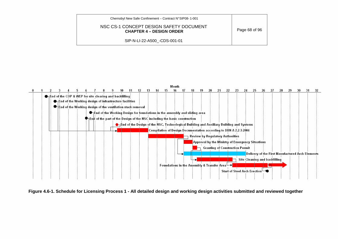
Chernobyl New Safe Confinement – Contract N° SIP08- 1-001
NSC CS-1 CONCEPT DESIGN SAFETY DOCUMENT CHAPTER 4 – DESIGN ORDER
SIP-N-LI-22-A500_-CDS-001-01
Page 68 of 96
Figure 4.6-1. Schedule for Licensing Process 1 - Al l detailed design and working design activities sub mitted and reviewed together
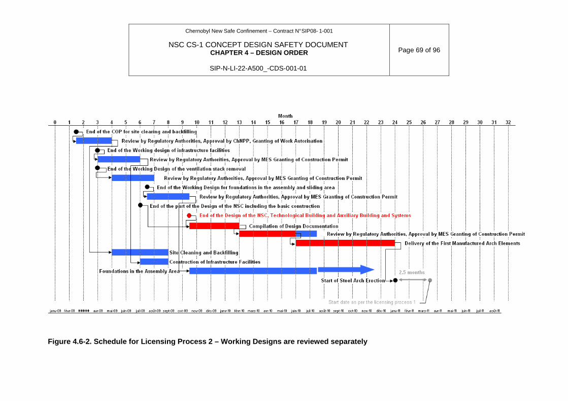
Chernobyl New Safe Confinement – Contract N° SIP08- 1-001
NSC CS-1 CONCEPT DESIGN SAFETY DOCUMENT CHAPTER 4 – DESIGN ORDER
SIP-N-LI-22-A500_-CDS-001-01
Page 69 of 96
Figure 4.6-2. Schedule for Licensing Process 2 – Wo rking Designs are reviewed separately

Chernobyl New Safe Confinement – Contract N° SIP08- 1-001
NSC CS-1 CONCEPT DESIGN SAFETY DOCUMENT CHAPTER 4 – DESIGN ORDER
SIP-N-LI-22-A500_-CDS-001-01
Page 70 of 96
Figure 4.6-3. Schedule for Licensing Process 3 – Wo rking Designs are reviewed separately and the NSC D esign is reviewed in two steps
Chernobyl New Safe Confinement – Contract N° SIP08- 1-001
NSC CS-1 CONCEPT DESIGN SAFETY DOCUMENT CHAPTER 4 – DESIGN ORDER
SIP-N-LI-22-A500_-CDS-001-01
Page 71 of 96
The above figures show that removing the preparatory works (site cleaning and backfilling), the construction of site facilities, the ventilation stack removal and the foundations in the assembly and sliding areas from the critical path allows reducing the duration of the project by circa 2.5 months. This time reduction is not very significant and is highly sensitive to potential delays.
Submitting the Design and associated documentation (SAR, EIAR, SCR) in two steps for the Arch, Technological Building and Auxiliary buildings allows reducing the duration of the project by an additional circa 6 months.
Licensing process 3 allows reducing the project duration by 8.5 months. This benefit is way more significant.
4.6.1.3 Comparative mobilisation analysis
Mobilisation features significant risk to the successful completion of the project. Indeed, the probability of failing to mobilise is totally proportional to the number of persons to get involved simultaneously. The more people have to be mobilised simultaneously, the more is the risk to fail and thus to miss the project deadlines.
The Detailed Design will be carried out with the maximum efficiency by NOVARKA and the UDO. The mobilisation of engineers and experts has been done without considering the various options proposed by the Licensing Plan. Nevertheless, at the end of the Design phase, after approval from the Regulatory Authorities of the Design and associated Technical Specifications, the call for tenders for SSC related to safety will be initiated at the same period. This will require additional resources to prepare invitation to tenderers and analyse the bids before placing the supply contracts. The fewer there will be tenders to analyse simultaneously, the fewer is the need for procurement engineers.
With this conclusion, licensing process 3 will require much less personnel simultaneously than the other options and therefore is less risky in terms of project schedule.
For the construction phase, simulation has been done on the basis of Gaussian curves to model the mobilisation / work / demobilisation of personnel for the various work steps. The result of this simulation is given in the figure below. The scale of the figure is such that the span between each horizontal line counts for circa 100 persons.
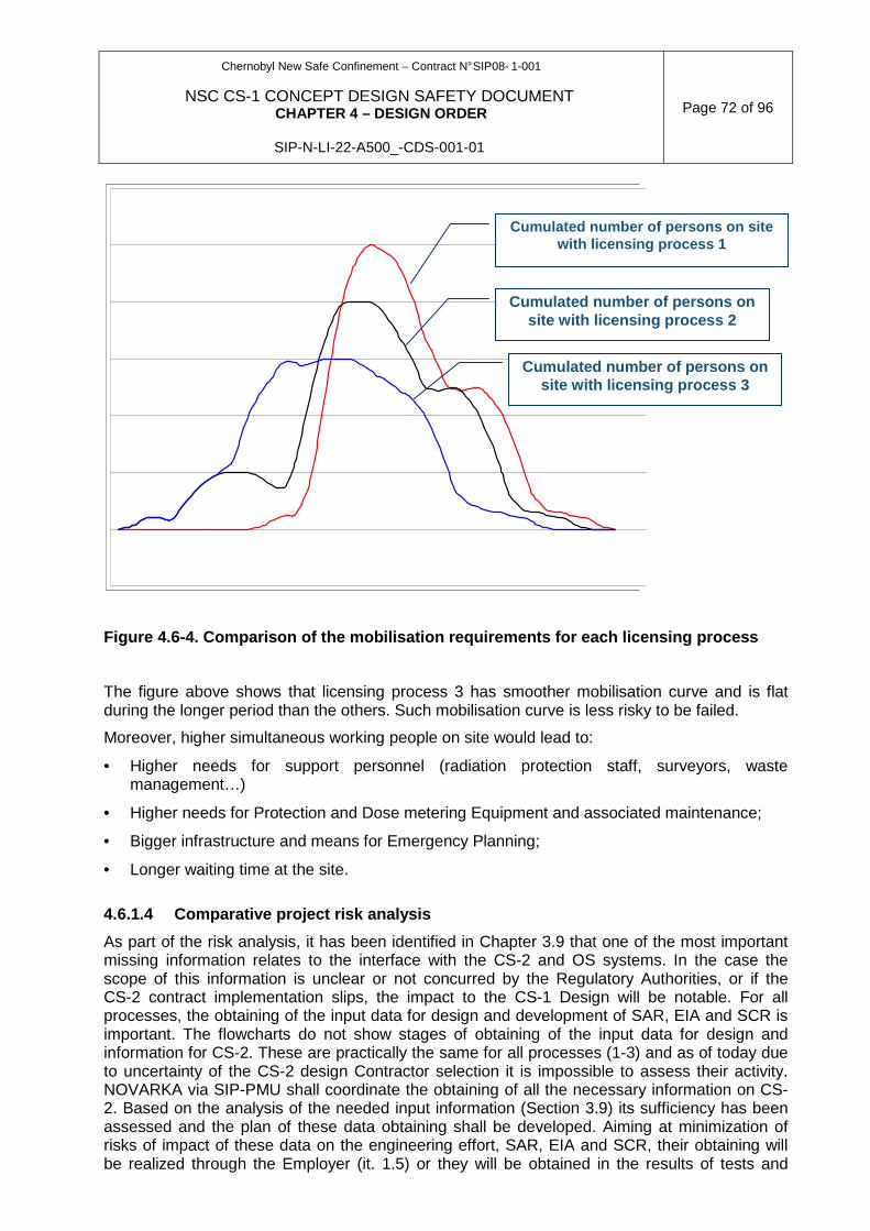
Chernobyl New Safe Confinement – Contract N° SIP08- 1-001
NSC CS-1 CONCEPT DESIGN SAFETY DOCUMENT CHAPTER 4 – DESIGN ORDER
SIP-N-LI-22-A500_-CDS-001-01
Page 72 of 96
Figure 4.6-4. Comparison of the mobilisation requir ements for each licensing process
The figure above shows that licensing process 3 has smoother mobilisation curve and is flat during the longer period than the others. Such mobilisation curve is less risky to be failed.
Moreover, higher simultaneous working people on site would lead to:
• Higher needs for support personnel (radiation protection staff, surveyors, waste management…)
• Higher needs for Protection and Dose metering Equipment and associated maintenance;
• Bigger infrastructure and means for Emergency Planning;
• Longer waiting time at the site.
4.6.1.4 Comparative project risk analysis
As part of the risk analysis, it has been identified in Chapter 3.9 that one of the most important missing information relates to the interface with the CS-2 and OS systems. In the case the scope of this information is unclear or not concurred by the Regulatory Authorities, or if the CS-2 contract implementation slips, the impact to the CS-1 Design will be notable. For all processes, the obtaining of the input data for design and development of SAR, EIA and SCR is important. The flowcharts do not show stages of obtaining of the input data for design and information for CS-2. These are practically the same for all processes (1-3) and as of today due to uncertainty of the CS-2 design Contractor selection it is impossible to assess their activity. NOVARKA via SIP-PMU shall coordinate the obtaining of all the necessary information on CS-2. Based on the analysis of the needed input information (Section 3.9) its sufficiency has been assessed and the plan of these data obtaining shall be developed. Aiming at minimization of risks of impact of these data on the engineering effort, SAR, EIA and SCR, their obtaining will be realized through the Employer (it. 1.5) or they will be obtained in the results of tests and
Cumulated number of persons on site with licensing process 3
Cumulated number of persons on site with licensing process 2
Cumulated number of persons on site with licensing process 1

Chernobyl New Safe Confinement – Contract N° SIP08- 1-001
NSC CS-1 CONCEPT DESIGN SAFETY DOCUMENT CHAPTER 4 – DESIGN ORDER
SIP-N-LI-22-A500_-CDS-001-01
Page 73 of 96
additional research on site to be performed by NOVARKA or subcontractors. The scheme of interfaces of NSC CS-1 design phases with the documents on safety assessment is presented in Fig. 4.6-5. The scheme shows what documents and data are required at different design stages and what materials from safety assessments of the various working designs will be used for development of SAR, EIA and SCR.
Licensing processes 1 and 2 feature the following risks:
• Systems and arch to be validated in the same process without opportunity to be on time in case of disruption. From this angle, licensing process 2 is less likely to be impacted by disruption than the others insofar as it includes fewer tasks on the critical path.
• The main areas for possible Design rejection by the Regulatory Authorities are those systems which interface with CS-2 and Object Shelter.
• If the Design and associated documentation fail to meet the Regulatory Requirements: the impact to the project is 15 d for document revision + 45 d of review by ChNPP/SIP-PMU + 120 d for Ukrgosstroyexpertise = 180 days (6 months)
• If any system design fails to meet its deadline, the whole duration of the project will be affected.
• The mobilisation is very sharp and its effectiveness is much more difficult to guarantee.
Licensing process 3 features the following risks:
• It is likely that the Regulatory Authorities might want clearer view on the auxiliary building before to concur the Design and associated documents of the NSC.
• In case of non-concurrence
− If the first step is refused: 15 d for document revision + 45 d (ChNPP) + 65 d (Regulatory Authorities) = 125 d (4 months)
− If the second step is refused: no delay because the gap between the end of the construction of the Auxiliary Building and the Commissioning phase is much higher than 4 months.
To overcome the main risk of licensing process 3, it is necessary to achieve quick agreement on the structure & contents of the 2-step licensing process to prevent the risk identified above. Specific technical decision will be produced for this purpose.
4.6.1.5 Conclusion – justification of the selection of the licensing process
Licensing process 3 where the working designs are reviewed separately and where the design of the NSC is reviewed in two consecutive steps present the main advantages to other licensing processes proposed in the Licensing Plan.
From a schedule point of view, licensing process 3 has much lighter critical path and has total duration up to 8.5 months lower than other licensing process options. It is also less sensitive from disruption of individual tasks. It is also less sensitive to the slipping of the CS-2 project and to the impact of the systems related to OS.
From a mobilisation angle, licensing process 3 requires fewer personnel simultaneously and has much smoother mobilisation curves than others. It is thus less sensitive to mobilisation failures which can impact the project duration.
Finally, from a global risk point of view, in the case the Design fails to meet the regulatory requirements, the additional review required by the Regulatory Authorities is 2-month shorter than for the other licensing processes and should be null for the part of the Design which is likely to be subject to more comments and discussions (Systems & interface with OS & CS2).
Chernobyl New Safe Confinement – Contract N° SIP08- 1-001
NSC CS-1 CONCEPT DESIGN SAFETY DOCUMENT CHAPTER 4 – DESIGN ORDER
SIP-N-LI-22-A500_-CDS-001-01
Page 74 of 96
4.6.2 COMPREHENSIVE STATE EXPERT REVIEW OF THE WORKING DOCUMENTS
FOR CONSTRUCTION OF INFRASTRUCTURE FACILITIES TO ERECT NSC CS-1, LAY TEMPORARY FOUNDATIONS AND DECONSTRUCT VENTILATION STACK AND RA AUTHORIZATION TOWARDS IMPLEMENTATION OF THE WORKS
In accordance with [2] and in order to meet the deadlines of the project, NOVARKA will develop the Working Designs and prepare the infrastructure facilities required for NSC CS-1 construction, construct its foundations and mobilise activities at the construction site, in parallel with development of NSC CS-1 Detailed Design documents.
According to [1], item 2.1.2.1 d), WD sections related to infrastructure facilities for NSC CS-1 construction and containing safety information about infrastructure facilities, are subjected to RA concurrence at the first stage of NSC project (item 10.2.1 [2]) during the Detailed Design of the NSC CS-1.
According to paragraph 2.1.2.2. a) [1] RA are entitled to separately review and agree WD for temporary foundations and WD for Ventilation Stack deconstruction
The following Working Designs will be submitted to the RA:
• COP and WEP for clearing of the site where Arch will be assembled and its systems;
• WD for construction of infrastructure facilities required for NSC construction (the list of facilities and relevant WDs will be defined during design);
• Working Design for the removal of the ventilation stack;
• Working Design for the construction of temporary foundations in the industrial zone.
The WD for infrastructure facilities to be created outside the ChNPP site will be submitted to RA for consideration. The list of facilities and relevant WDs will be defined during design.
WD will be submitted in such a way to get timely Authorisation to proceed with works on creation of infrastructure facilities required for NSC CS-1 construction.
COP and WEP for clearing of the site where Arch will be assembled and its systems will be developed according to [3 and 5] and contain section on safety assessment in compliance with recommendations [6, except Section 3.2]
The Working Design for infrastructure facilities for NSC CS-1 construction will consist of:
• Design documents (including the Construction Organisation Plans, that will be developed in accordance with [3, 4, 5];
• Safety assessment section (for DD are to be realized at the ChNPP site), developed in compliance with the Recommendations on the Structure and Contents of the Shelter Safety Status Report [6] and consideration of the report itself [7];
• Environmental section, developed in compliance with item Д2 of Attachment to [8].
In addition to the abovementioned, WD for temporary foundations will demonstrate the consistency of projects of temporary foundations and the permanent structure in accordance with the provisions of the document titled “Proposal on Ahead-of-Schedule Construction of Temporary Foundations NSC sliding-over and Arrangement of "Assembly area" for Arch Structures Preassembly” (rev. 03 dated 20.01.05) [23] approved by the SNRCU, and take into account provisions for the scope of safety justification set forth in [23].
During the RA’s review of the Working Design for infrastructure facilities for NSC CS-1 construction, as well as during its regulatory decision-making, early interface procedure will be as follows:
• SSE ChNPP will submit the documents to “Ukrderzhbudexpertise”, in Ukrainian/Russian and English languages (including electronic versions).
Chernobyl New Safe Confinement – Contract N° SIP08- 1-001
NSC CS-1 CONCEPT DESIGN SAFETY DOCUMENT CHAPTER 4 – DESIGN ORDER
SIP-N-LI-22-A500_-CDS-001-01
Page 75 of 96
• SE “Ukrderzhbudexpertise” will make a comprehensive state expertise in accordance with
[9] involving the other RA and/or its EO, as stated in Section 4.6.7.
• In the course of the comprehensive state expert review of documents to resolve safety problems and comments (if any appears during the document review), interrelation will be organised between the RA, EO, SSE ChNPP, NOVARKA (under coordination of “Ukrderzhbudexpertise”).
• Based on the results of the expertise, “Ukrderzhbudexpertise” will prepare report on comprehensive state expert review and forward it to SSE ChNPP.
• In accordance with [9] the duration of the comprehensive state expertise of documents (if contract between SSE ChNPP and SE “Ukrderzhbudexpertise” is signed) should not exceed 45 calendar days (between the delivery of complete documents to “Ukrderzhbudexpertise” and the transmission of the comprehensive state expertise report to SSE ChNPP).
• If SSE ChNPP submits to “Ukrderzhbudexpertise” revised documents which take into account comments before the term of review expired “Ukrderzhbudexpertise”/SSE ChNPP Protocol action item will specify term for review of revised documents as review extension. In other cases “Ukrderzhbudexpertise” within the specified period of time will send to SSE ChNPP comprehensive review conclusion containing comments. After revision of documents SSE ChNPP submits the documentation to “Ukrderzhbudexpertise” for second comprehensive state expert review. The second comprehensive state expert review is made following the same procedure as the first one.
• In case of positive results both from nuclear and radiation safety state expert review and considering the results of the comprehensive state expert review, SNRCU will send letters on stating its agreement on the Working Design (specifically related to nuclear and radiation safety);
• In accordance with [3] the Ministry of Emergency Situations and / or SSE ChNPP will approve each Working Design.
• After receipt of “Ukrderzhbudexpertise” positive decision on comprehensive state expertise and agreement on Working Design, the Regulatory Authorities will issue authorisation to proceed to SSE ChNPP.
SSE ChNPP will receive authorization to proceed from the following authorities: а) State Architecture and Construction Supervisory Inspection Body (SACS) of Ukraine – in accordance with [10], paragraph 2.1.4 [1]; b) State Municipal Industrial Inspectorate – in accordance with [11, paragraph 2.4 [1], if necessary; c) State Fire Safety Department, Ministry of Emergency – in accordance with [12] paragraph 2.3 [1]; d) Ministry of Health – if necessary, sanitary passport (or its modification) in accordance with [13]. To initiate the works, SSE ChNPP will get permission of State nuclear and radiation safety inspection at the ChNPP in accordance with [14] and consideration of the earlier accepted permissions.
4.6.3 RA’s CONCURRENCE OF DOCUMENTS CONTAINING THE ADDITIONAL DESIGN CRITERIA, REQUIREMENTS AND INITIAL DATA FOR NSC CS-1 DESIGNING
In accordance with [1] item 2.1.2.2 а), during the Detailed Design of the second stage of NSC project (paragraph 10.2.2 [2]), commissioning stage 1, documents containing important design criteria and requirements, not specified in the NSC conceptual design (FS) and being the responsibility of NOVARKA, will be subject to RA concurrence.
Chernobyl New Safe Confinement – Contract N° SIP08- 1-001
NSC CS-1 CONCEPT DESIGN SAFETY DOCUMENT CHAPTER 4 – DESIGN ORDER
SIP-N-LI-22-A500_-CDS-001-01
Page 76 of 96
The following items may be submitted to RA if needed, separately or grouped with Technical Decisions:
• Design criteria and requirements to temporary foundations (see paragraph 2.1.2.2 [13]) – Document 1.21 in Table 4.6.1;
• Specified aerodynamic factors specified in the results of testing the NSC CS-1 model creation in aerodynamic tunnel (see section 2.3.1.2) – Document 1.1 in Table 4.6.1
• Criteria and requirements (or model) to record dynamic impacts under snow and ice melting from NSC localizing building (see section 2.3.1.3) – Document 1.1 in Table 4.6.1
• Specified criteria and requirements on fire safety (in particular the results of thermodynamic analyses of maximal internal fire, testing of structures material, etc.) (see sections 2.3.3.1 & 2.9.3) – Document 1.22 in Table 4.6.1
• Specified designed architectural criteria (see section 2.3.3.2 & 2.4.6 RA recommendations 3.3 on draft CDSD). – Document 1.2 in Table 4.6.1
• Results of the additional geotechnical investigations of site and full-scale test of piles (see section 2.4.5). – Document 1.10 and 1.11 in Table 4.6.1
• Specified criteria and requirements for designing of NSC foundations (per results of the additional investigations of the site and full-scale test of piles) (see section 2.4.5) – Document 1.12 in Table 4.6.1
• Specified criteria of NSC long term tightness (see section 2.6.4 and RA’s recommendation 3.3) – Document 1.16 in Table 4.6.1
• Specified criteria of temperature-humidity conditions inside the NSC (see section 2.7). – Document 1.3 in Table 4.6.1
• Specified criteria of ventilation; – Document 1.19 in Table 4.6.1 (see note below)
• Specified criteria for RAW transfer from NSC to ChNPP’s radwaste management facilities (see section 2.8). – Document 1.17 in Table 4.6.1
• Criteria and requirements to structures and protection of equipment, pipelines, control cabinets and cable lines (see RA’s recommendation 3.5 to CDSD). – Document 1.18 in Table 4.6.1
• Criteria and requirements to Software and its verification (see RA’s recommendation 3.5 to CDSD). – Document 1.1 in Table 4.6.1
• Criteria and requirements to technical diagnosis, tests, metrological assurance (see RA’s recommendation 3.5 to CDSD). – Document 1.20 in Table 4.6.1
• Other documents containing specific (additional) criteria and requirements determined or identified during the Design. – Document 1.23 in Table 4.6.1
• Other specified (additional) initial data determined or identified during the Design. – Document 1.23 in Table 4.6.1
• Documents dealing with application of other countries normative documents’ requirements. – Document 1.13 in Table 4.6.1
• Methods and models to be used during NSC CS-1 designing (see Section 4.3). – Document 1.14 in Table 4.6.1
• Test programs in the course of NSC CS-1 designing. – Document 1.15 in Table 4.6.1
Documents containing the additional criteria, requirements and initial data will be submitted as early as feasible during the Detailed Design of the NSC CS-1.

Chernobyl New Safe Confinement – Contract N° SIP08- 1-001
NSC CS-1 CONCEPT DESIGN SAFETY DOCUMENT CHAPTER 4 – DESIGN ORDER
SIP-N-LI-22-A500_-CDS-001-01
Page 77 of 96
The documents containing the additional criteria, requirements and initial data will consist of:
• Technical Decision (TD) on establishment of the design criteria, requirements and initial data for the Detailed Design of the NSC CS-1;
• Explanatory Note (EN) with necessary substantiations for TD and its information.
The TD will be developed in accordance with [15]. The TD will contain accurate unambiguous information and reference on the establishment of particular criteria, requirements and initial data, as well as on interrelationship with the criteria, requirements and initial data given in CDSD. The EN will be developed in compliance with [15]. The EN will contain comprehensive substantiations of the design criteria, requirements and initial data, established in the TD.
The specific features of TD and EN contents are given below by type.
Note: The ventilation criteria are outstanding and unsolved issue. Combined meeting of the criteria relating to humidity and temperature together with the radiological criteria inside the NSC main volume leads to a range of technical options in terms of flow-rate and heating requirements for which a mutual agreement has to be found as soon as achievable after the CDSD concurrence. This agreement being found, the design of the fans, ducts, filtration means and so on will be initiated, keeping in mind the requirements in terms of investment and operation costs.
а) TD on investigation, tests performance will conta in appropriate programs of investigations and tests.
Accordingly, the EN will contain substantiation of:
• Purposes of investigations and tests;
• Scope, technique and procedures of investigations and tests;
• Characteristic and parameters (classification, errors, validity, etc.) which will be obtained as the result of investigations and testing.
b) TD on establishment of criteria, requirements an d initial data per results of investigations and tests will contain the obtained characteristic and parameters accompanied by designation of their errors, validit y, etc.
Properly, the following will be given and substantiated in the EN:
• Program of investigations and tests (if it was not previously concurred by the RA);
• Description of investigations, tests done and appropriate results;
• Analysis of the results obtained by investigation and testing.
c) TD on application of methods (models) during the Detailed Design of the NSC CS-1 will contain information characterising the methods (mod els) and their application.
Properly, the EN will contain substantiation of the method (model) application; the following type of information will be provided:
• Purpose, field and experience relative to the application of methods and models;
• Contents of the methods and models, including the basic hypothesis accepted, assumptions, limitations, processes considered, impacts, mathematical methods used, models, software, etc.;
• Compliance of the methods and models with the requirements of appropriate normative documents to perform the analysis, calculations, etc.;
Chernobyl New Safe Confinement – Contract N° SIP08- 1-001
NSC CS-1 CONCEPT DESIGN SAFETY DOCUMENT CHAPTER 4 – DESIGN ORDER
SIP-N-LI-22-A500_-CDS-001-01
Page 78 of 96
• Verification of methods, models and software;
• Validity and accuracy of the results.
d) TD on application of foreign normative documents will contain appropriate requirements.
Scope of needed data for analyses and justifications will be defined in each specific case at the beginning of EN development, interfacing with the RA and their EO. The procedure for interrelationship during the RA and its EO review and concurrence of the documents containing the additional criteria, requirements and initial data, and during the RA decision-making consists of the following steps:
• SSE ChNPP will submit the TD and EN about establishment of the additional design criteria, requirements and initial data to the SNRCU in Ukrainian/Russian and English (including the electronic versions).
• The SNRCU will review the documents with the participation of any other RA, as it is defined in section 4.6.7. During the review of the documents, the SNRCU and SSTC will coordinate with other RA, EO, SSE ChNPP and NOVARKA with the objective of solving the safety issues. The interrelationship will be carried out in compliance with the procedures established in [1, 16, 17, 18].
• Based on the results of the review of documents, the RA will make regulatory decision on TD agreement or non-agreement. The EN is not subject to agreement and is considered as a document substantiating the TD.
• The SNRCU will provide all regulatory decisions made by the other RA to the SSE ChNPP.
In accordance with [1] item 2.2.2, the necessary period for RA concurrence of the deliverables (period between delivery of documents to SNRCU and the regulatory decisions sent to the SSE ChNPP) is 45 calendar days.
4.6.4 REVIEW AND COMMENT OF RA ON DOCUMENTS FROM THE DESIGN SETS
In compliance with item 2.2 [19] in the course of development of NSC CS-1 design NOVARKA will substantiate the safety, in particular, logically completed parts of the NSC CS-1 design documentation (design packages). Those design packages with substantiations will be submitted to RA in turn.
NOVARKA will use the possibility to submit early versions of the design packages including dedicated safety information on the basis of the document [20].
Before any submission, NOVARKA will submit to ChNPP, Structure and Contents of the Design Packages based on the aforementioned references. If ChNPP states it relevant, ChNPP will submit these Structure and contents to the Regulatory Authorities for concurrence.
Interrelationship procedure under consideration of the design sets by RA and its EO:
• SSE ChNPP will review the design set and submit it to SNRCU in parallel in Ukrainian or Russian and English languages (including the electronic versions).
• SNRCU will arrange concurrence of the documents with other RA, as it is stated in the Licensing Plan [1].
• Based on the results of Design concurrence, the RA and/or its EO will prepare comments on the design packages. SNRCU will submit comments of all RA (and their EO) to SSE ChNPP.
Chernobyl New Safe Confinement – Contract N° SIP08- 1-001
NSC CS-1 CONCEPT DESIGN SAFETY DOCUMENT CHAPTER 4 – DESIGN ORDER
SIP-N-LI-22-A500_-CDS-001-01
Page 79 of 96
• NOVARKA will assess the comments of RA and its EO, as well as SSE ChNPP’s additional
recommendations to the RA’s and EO’s comments on the design packages and prepare proposals for their resolution;
• SSE ChNPP, NOVARKA, the RA and its EO will discuss comment to reach inter-consistent solution in compliance with the procedures [17, 18].
• As a result, the decisions agreed together by SSE ChNPP and NOVARKA, will be sent to SNRCU for information by SSE ChNPP. The updated design packages will not be sent to SNRCU.
Any interaction will be realized in compliance with the procedures [17, 18].
4.6.5 COMPREHENSIVE STATE EXPERT REVIEW ON THE COMPLETE DESIGN DOCUMENTATION OF THE NSC-CS1 AND RA’S AUTHORISATION TO PROCEED WITH NSC CS-1 CONSTRUCTION
During Design, Safety Analysis Report (SAR), Sanitary Compliance Report (SCR) and Environmental Impact Assessment (EIA) will be prepared. The SAR will be developed in compliance with requirements [21], the SCR will be in compliance with requirements [22], and the EIA will be in compliance with requirements [8].
The Design of the Arch and its systems pertain significant regulatory and project risks, as follows:
• The risks relating to the geometric complexity and the gigantism of the Arch;
• The risks relating to the complexity and the multiplicity of interfaces between systems.
Both risks are subject to detailed consideration with the objective of keeping high degree of radiological safety (among others) but the nature and the scope of the safety assessment slightly differs one from the other. Therefore, the NSC CS-1 Design shall be submitted for RA review parts by parts as follows:
• Part of the NSC CS-1 design, containing the design of the Arch and main cranes, the permanent foundations and the roofing & cladding (item 10.2.2.1 [2], items 1, 2, & 3 partially);
• The complete Design of the NSC CS-1 including the design of life-support technological systems and NSC monitoring systems (item 10.2.2.1 [2], items 4, 5, 6, 8 & 3 partially).
This approach derives also the benefit of removing the Design of the systems from the critical path of the project. This will allow consideration of the modifications demanded by the Regulatory Authorities on the Arch and Cranes and their extrapolation to the Design of systems. The Design Documents for the first step contain:
• The Design documents (including COP) containing the design of the Arch (including the arch, western and eastern end walls, junctions with existing structures), and main cranes, the permanent foundations and the roofing & cladding, internal NSC arrangement, sliding system,to be developed in compliance with [3, 4, 5];
• SAR for this part of Design to be developed in compliance with [21];
• SCR for this part of Design to be developed in compliance with [22];
• EIA for this part of Design to be developed in compliance with [8].
The format and contents of these preliminary documents will be submitted to the Regulatory Authorities prior to their elaboration.
Interrelationship procedure under consideration of the design sets by RA and its EO:
Chernobyl New Safe Confinement – Contract N° SIP08- 1-001
NSC CS-1 CONCEPT DESIGN SAFETY DOCUMENT CHAPTER 4 – DESIGN ORDER
SIP-N-LI-22-A500_-CDS-001-01
Page 80 of 96
• SSE ChNPP will review the design package and submit it to SNRCU in parallel in SE
Ukrderzhbudekspertise in Ukrainian or Russian and English languages (including the electronic versions).
• SE Ukrderzhbudekspertise will arrange concurrence of the documents with other RA, as it is stated in the Licensing Plan [1].
• Based on the results of Design concurrence, the RA and/or its EO will prepare comments on the design packages. For the purposes of analysis of the design package the principle of the early interaction shall be used when the technical specialists of SSE ChNPP and NOVARKA shall provide the necessary clarifications during the technical meetings with experts of RA and EO. SE Ukrderzhbudekspertise will submit comments of all RA (and their EO) to SSE ChNPP.
• NOVARKA will assess the comments of RA and its EO, as well as SSE ChNPP’s additional recommendations to the design packages and prepare proposals for their resolution;
The Design for the NSC CS-1 (second step) containing documents of the first stage above plus design documents of the life-support technological systems and NSC monitoring systems state consist of:
• Design documents (including COP.) in full extent to be developed in compliance with [3, 4, 5];
• SAR in full scope to be developed in compliance with [21];
• SCR in full scope to be developed in compliance with [22];
• EIA in full scope to be developed in compliance with [8].
During the development of NSC CS-1 Design, the NSC and the OS will be considered as an integrated facility. The SAR, EIA and SCR will contain comprehensive safety, sanitary and environmental analysis of the NSC and the OS. They will be based on the status reports of the OS meeting the scheme presented in Fig. 4.6-5.
During the review by the RA and its EO of the completed NSC CS-1 design and RA’s regulatory decision, the interaction procedure will include the following steps:
• SSE ChNPP will submit the defined documents to SE “Ukrderzhbudexpertise” in Ukrainian/Russian and English (including electronic versions).
• SE “Ukrderzhbudexpertise” will make comprehensive state expertise in accordance with [9]; other RA and/or EO might be involved, as it was pointed out in Table 4.6-2.
During the Comprehensive State Expert Review of documents, interaction among RA, SSE ChNPP, NOVARKA (under coordination of SE “Ukrderzhbudexpertise”) will be required to resolve urgent safety issues (if such issues are identified by the EO during review of documents).
• Depending on the results of the expertises, SE “Ukrderzhbudexpertise” will prepare report on Comprehensive State Expert Review and submit it to SSE ChNPP.
• In accordance with [1] and depending on the availability of the contract made between SSE ChNPP and SE “Ukrderzhbudexpertise” (the period between the receipt of documents by SE “Ukrderzhbudexpertise” and the submittal of expert report on comprehensive state expertise to SSE ChNPP) the due dates of documents’ Comprehensive State Expert Review should not exceed the following:
− For the first part of the NSC CS-1 Design including Arch design, main cranes, permanent foundations, cladding and roofing: 65 calendar days;
− For the above part plus the life support and monitoring systems: 65 calendar days.

Chernobyl New Safe Confinement – Contract N° SIP08- 1-001
NSC CS-1 CONCEPT DESIGN SAFETY DOCUMENT CHAPTER 4 – DESIGN ORDER
SIP-N-LI-22-A500_-CDS-001-01
Page 81 of 96
− If SSE ChNPP submits to SE “Ukrderzhbudexpertise” revised documents which take into
account comments before the term of review expired, SE “Ukrderzhbudexpertise”/SSE ChNPP Protocol action item will specify the term for review of revised documents as review extension. In other cases SE “Ukrderzhbudexpertise” within the specified period of time will send to SSE ChNPP comprehensive review conclusion containing comments. After revision of documents SSE ChNPP submits the documentation to SE “Ukrderzhbudexpertise” for second Comprehensive State Expert Review. The second comprehensive state expert review follows the same procedure as the first one.
• On the basis of the positive conclusion of the state nuclear and radiation safety expert review and taking into account conclusion of comprehensive state expert review, the SNRCU will send letters informing about their agreement on the submitted parts of NSC CS-1 design (specifically related to nuclear and radiation safety).
• In compliance with [3] SSE ChNPP will submit parts of NSC CS-1 Design to the Ministry of
Emergencies of Ukraine for approval. After receipt of positive expert report from SE “Ukrderzhbudexpertise” and its approval, SSE ChNPP will get the RA’s authorisation to proceed with works. This authorisation will be given upon advice from: а) State Architecture and Construction Supervisory Inspection Body (SACS) of Ukraine – in accordance with [10], paragraph 2.1.4 [1]; b) State Municipal Industrial Inspectorate – in accordance with [11, paragraph 2.4 [1], if necessary; c) State Fire Safety Department, Ministry of Emergency – in accordance with [12] paragraph 2.3 [1]; d) Ministry of Health – if necessary, sanitary passport (or its modification) in accordance with [13]. In order to start the work, SSE ChNPP shall get permission of the State nuclear and radiation safety inspection at ChNPP in compliance with [14], taking into account the previous authorisations.
4.6.6 REGULATORY AGREEEMENT OF TECHNICAL SPECIFICATIONS FOR EQUIPMENT AND SYSTEMS RELATED TO RADIATION, NUCLEAR, FIRE AND INDUSTRIAL SAFETY
According to paragraph 2.1.2.2 Technical Specifications (TS) for Equipment, Systems Related to Radiation, Nuclear, Fire and Industrial Safety are subject to regulatory agreement. TS are reviewed and agreed by RA as part of the agreed design or on its basis). The list of TS which will be reviewed on the basis of completely agreed CS-1 NSC Design or its agreed portion will be defined in CS-1 NSC Design (or its portion). TS will be developed with consideration of requirements [25 and 26]. Procedure for interface during review and agreement of TS by RA and their EO and making regulatory decisions lies in the following: • SSE ChNPP will submit TS to the SNRCU in Ukrainian/Russian and English languages
(including electronic versions).
Chernobyl New Safe Confinement – Contract N° SIP08- 1-001
NSC CS-1 CONCEPT DESIGN SAFETY DOCUMENT CHAPTER 4 – DESIGN ORDER
SIP-N-LI-22-A500_-CDS-001-01
Page 82 of 96
• The SNRCU will review TS with involvement of other RA. In order to resolve safety
problems during review of documents the SNRCU along with SSTC NRS will manage coordinated interface between RA, EO, SSE ChNPP and NOVARKA. Interface will be based on procedures established in [1, 16, 17 and 18].
• Based on the results of the expertise, RA will make regulatory decisions on agreement (or
disagreement) of TS. • The SNRCU will send regulatory decisions made by all RA to SSE ChNPP. In accordance with paragraph 2.2.2 [1] the established term for regulatory review of documents (the term between the SNRCU receiving the full set of documents and sending a set of regulatory decisions to SSE ChNPP) constitutes 45 calendar days.
Design criteria and requirements should be developed (detailed) during the design process and send for agreement with the regulatory authorities before the submittal design CS-1 NSC to the expertize and as a part of the design CS-1 NSC.
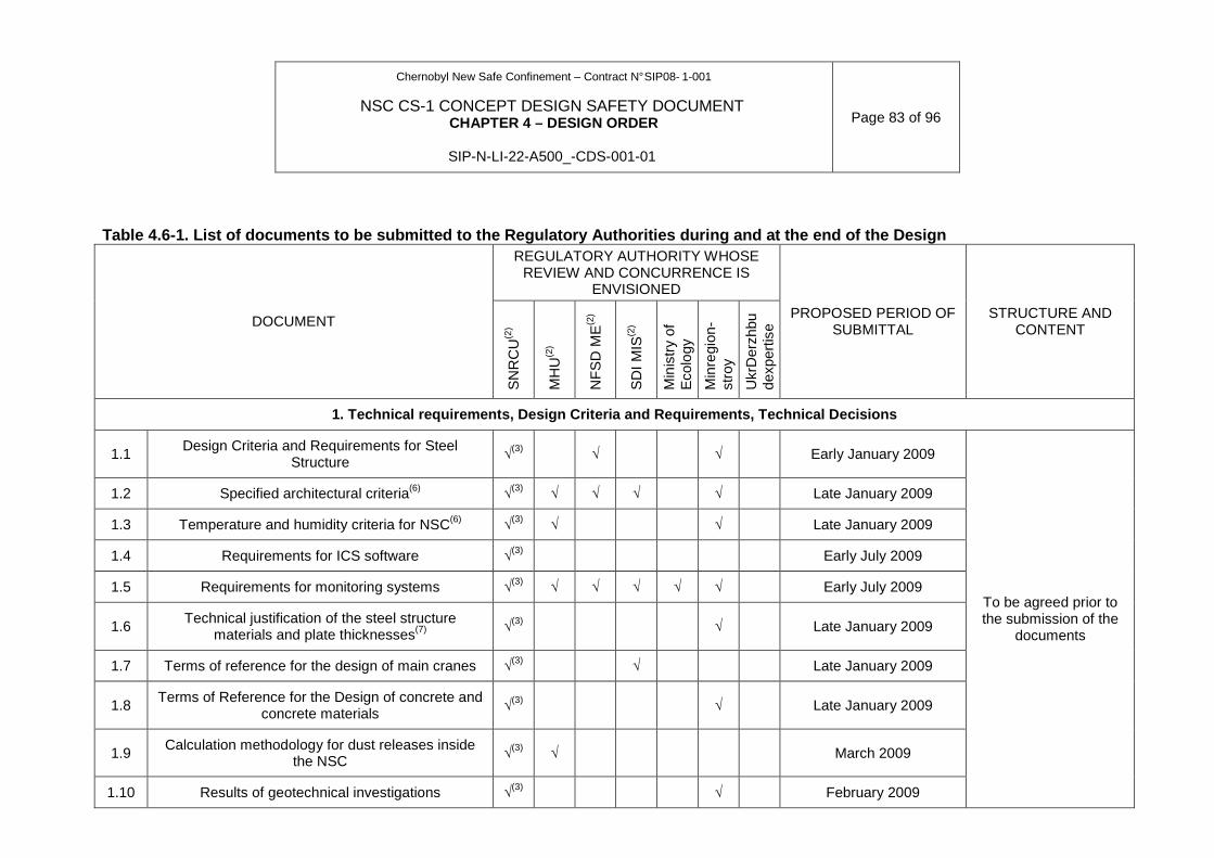
Chernobyl New Safe Confinement – Contract N° SIP08- 1-001
NSC CS-1 CONCEPT DESIGN SAFETY DOCUMENT CHAPTER 4 – DESIGN ORDER
SIP-N-LI-22-A500_-CDS-001-01
Page 83 of 96
Table 4.6-1. List of documents to be submitted to t he Regulatory Authorities during and at the end of the Design REGULATORY AUTHORITY WHOSE
REVIEW AND CONCURRENCE IS ENVISIONED
DOCUMENT
SN
RC
U(2
)
MH
U(2
)
NF
SD
ME
(2)
SD
I MIS
(2)
Min
istr
y of
E
colo
gy
Min
regi
on-
stro
y
Ukr
Der
zhbu
dexp
ertis
e
PROPOSED PERIOD OF SUBMITTAL
STRUCTURE AND CONTENT
1. Technical requirements, Design Criteria and Requ irements, Technical Decisions
1.1 Design Criteria and Requirements for Steel
Structure √
(3) √ √ Early January 2009
1.2 Specified architectural criteria(6) √(3) √ √ √ √ Late January 2009
1.3 Temperature and humidity criteria for NSC(6) √(3) √ √ Late January 2009
1.4 Requirements for ICS software √(3) Early July 2009
1.5 Requirements for monitoring systems √(3) √ √ √ √ √ Early July 2009
1.6 Technical justification of the steel structure
materials and plate thicknesses(7) √
(3) √ Late January 2009
1.7 Terms of reference for the design of main cranes √(3) √ Late January 2009
1.8 Terms of Reference for the Design of concrete and
concrete materials √
(3) √ Late January 2009
1.9 Calculation methodology for dust releases inside
the NSC √
(3) √ March 2009
1.10 Results of geotechnical investigations √(3) √ February 2009
To be agreed prior to the submission of the
documents
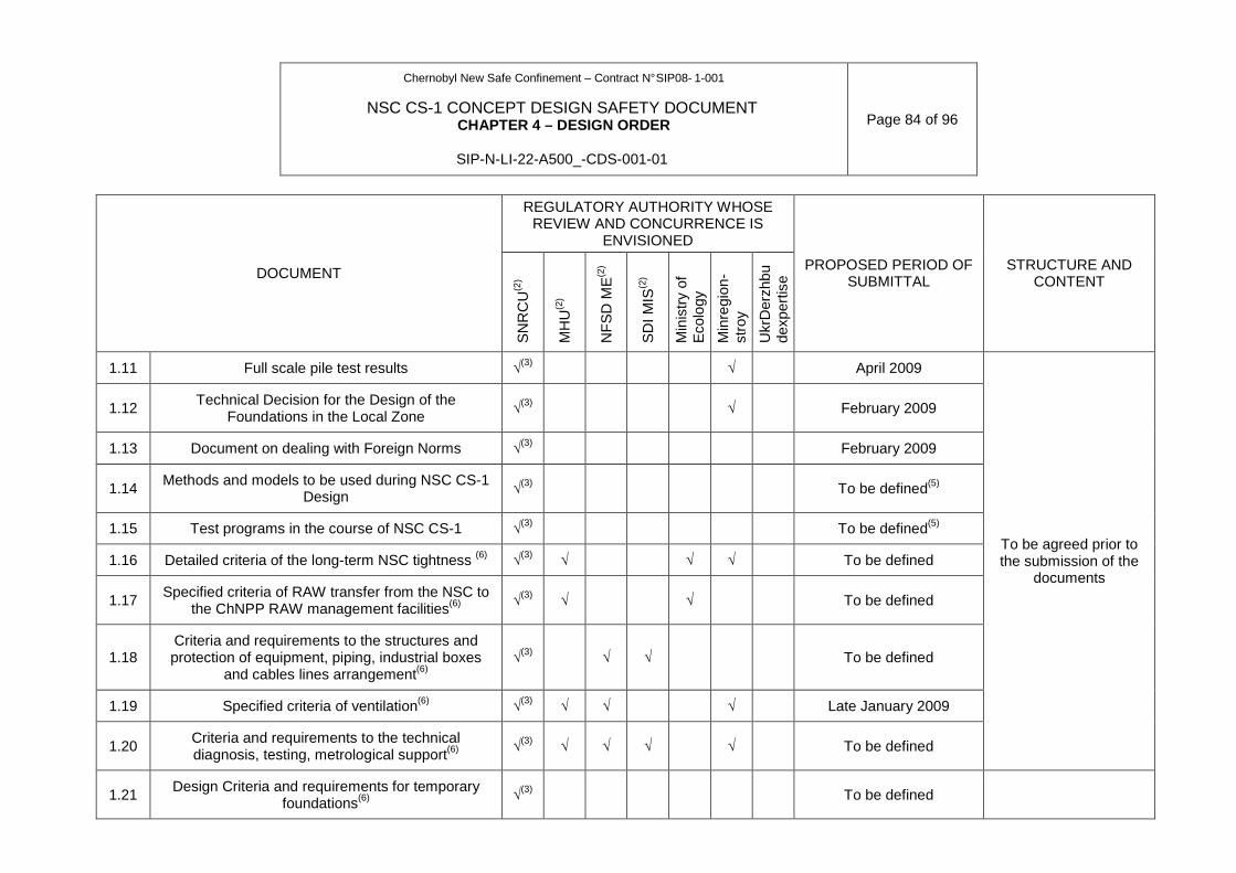
Chernobyl New Safe Confinement – Contract N° SIP08- 1-001
NSC CS-1 CONCEPT DESIGN SAFETY DOCUMENT CHAPTER 4 – DESIGN ORDER
SIP-N-LI-22-A500_-CDS-001-01
Page 84 of 96
REGULATORY AUTHORITY WHOSE
REVIEW AND CONCURRENCE IS ENVISIONED
DOCUMENT
SN
RC
U(2
)
MH
U(2
)
NF
SD
ME
(2)
SD
I MIS
(2)
Min
istr
y of
E
colo
gy
Min
regi
on-
stro
y
Ukr
Der
zhbu
dexp
ertis
e
PROPOSED PERIOD OF SUBMITTAL
STRUCTURE AND CONTENT
1.11 Full scale pile test results √(3) √ April 2009
1.12 Technical Decision for the Design of the
Foundations in the Local Zone √
(3) √ February 2009
1.13 Document on dealing with Foreign Norms √(3) February 2009
1.14 Methods and models to be used during NSC CS-1
Design √
(3) To be defined(5)
1.15 Test programs in the course of NSC CS-1 √(3) To be defined(5)
1.16 Detailed criteria of the long-term NSC tightness (6) √(3) √ √ √ To be defined
1.17 Specified criteria of RAW transfer from the NSC to
the ChNPP RAW management facilities(6) √
(3) √ √ To be defined
1.18 Criteria and requirements to the structures and protection of equipment, piping, industrial boxes
and cables lines arrangement(6) √
(3) √ √ To be defined
1.19 Specified criteria of ventilation(6) √(3) √ √ √ Late January 2009
1.20 Criteria and requirements to the technical diagnosis, testing, metrological support(6)
√(3) √ √ √ √ To be defined
To be agreed prior to the submission of the
documents
1.21 Design Criteria and requirements for temporary
foundations(6) √
(3) To be defined
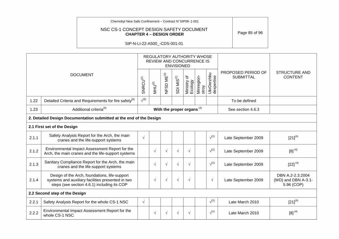
Chernobyl New Safe Confinement – Contract N° SIP08- 1-001
NSC CS-1 CONCEPT DESIGN SAFETY DOCUMENT CHAPTER 4 – DESIGN ORDER
SIP-N-LI-22-A500_-CDS-001-01
Page 85 of 96
REGULATORY AUTHORITY WHOSE
REVIEW AND CONCURRENCE IS ENVISIONED
DOCUMENT
SN
RC
U(2
)
MH
U(2
)
NF
SD
ME
(2)
SD
I MIS
(2)
Min
istr
y of
E
colo
gy
Min
regi
on-
stro
y
Ukr
Der
zhbu
dexp
ertis
e
PROPOSED PERIOD OF SUBMITTAL
STRUCTURE AND CONTENT
1.22 Detailed Criteria and Requirements for fire safety(6) √(3) To be defined
1.23 Additional criteria(6) With the proper organs (3) See section 4.6.3
2. Detailed Design Documentation submitted at the e nd of the Design
2.1 First set of the Design
2.1.1 Safety Analysis Report for the Arch, the main
cranes and the life-support systems √ √
(1) Late September 2009 [21](4)
2.1.2 Environmental Impact Assessment Report for the
Arch, the main cranes and the life-support systems √ √ √ √ √
(1) Late September 2009 [8] (4)
2.1.3 Sanitary Compliance Report for the Arch, the main
cranes and the life-support systems √ √ √ √ √
(1) Late September 2009 [22] (4)
2.1.4 Design of the Arch, foundations, life-support
systems and auxiliary facilities presented in two steps (see section 4.6.1) including its COP
√ √ √ √ √ Late September 2009 DBN A.2-2.3.2004
(WD) and DBN A-3.1-5.96 (COP)
2.2 Second step of the Design
2.2.1 Safety Analysis Report for the whole CS-1 NSC √ √(1) Late March 2010 [21](4)
2.2.2 Environmental Impact Assessment Report for the whole CS-1 NSC
√ √ √ √ √(1) Late March 2010 [8] (4)
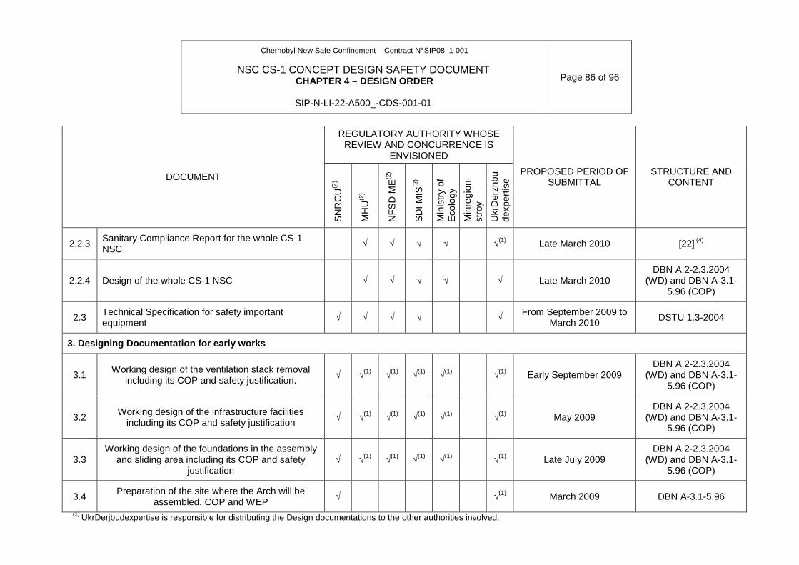
Chernobyl New Safe Confinement – Contract N° SIP08- 1-001
NSC CS-1 CONCEPT DESIGN SAFETY DOCUMENT CHAPTER 4 – DESIGN ORDER
SIP-N-LI-22-A500_-CDS-001-01
Page 86 of 96
REGULATORY AUTHORITY WHOSE
REVIEW AND CONCURRENCE IS ENVISIONED
DOCUMENT
SN
RC
U(2
)
MH
U(2
)
NF
SD
ME
(2)
SD
I MIS
(2)
Min
istr
y of
E
colo
gy
Min
regi
on-
stro
y
Ukr
Der
zhbu
dexp
ertis
e
PROPOSED PERIOD OF SUBMITTAL
STRUCTURE AND CONTENT
2.2.3 Sanitary Compliance Report for the whole CS-1 NSC
√ √ √ √ √(1) Late March 2010 [22] (4)
2.2.4 Design of the whole CS-1 NSC √ √ √ √ √ Late March 2010 DBN A.2-2.3.2004
(WD) and DBN A-3.1-5.96 (COP)
2.3 Technical Specification for safety important equipment
√ √ √ √ √ From September 2009 to March 2010
DSTU 1.3-2004
3. Designing Documentation for early works
3.1 Working design of the ventilation stack removal
including its COP and safety justification. √ √
(1) √(1) √
(1) √(1) √
(1) Early September 2009 DBN A.2-2.3.2004
(WD) and DBN A-3.1-5.96 (COP)
3.2 Working design of the infrastructure facilities
including its COP and safety justification √ √
(1) √(1) √
(1) √(1) √
(1) May 2009 DBN A.2-2.3.2004
(WD) and DBN A-3.1-5.96 (COP)
3.3 Working design of the foundations in the assembly
and sliding area including its COP and safety justification
√ √(1) √
(1) √(1) √
(1) √(1) Late July 2009
DBN A.2-2.3.2004 (WD) and DBN A-3.1-
5.96 (COP)
3.4 Preparation of the site where the Arch will be
assembled. COP and WEP √ √
(1) March 2009 DBN A-3.1-5.96
(1) UkrDerjbudexpertise is responsible for distributing the Design documentations to the other authorities involved.
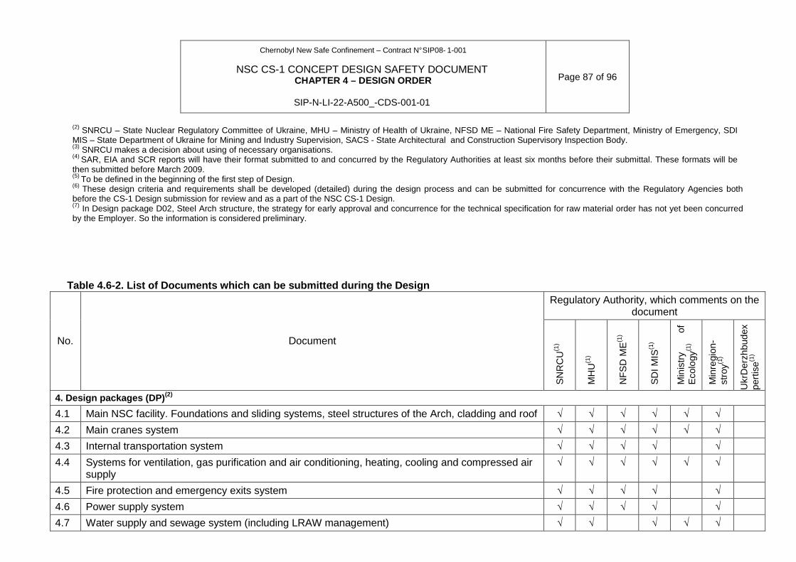
Chernobyl New Safe Confinement – Contract N° SIP08- 1-001
NSC CS-1 CONCEPT DESIGN SAFETY DOCUMENT CHAPTER 4 – DESIGN ORDER
SIP-N-LI-22-A500_-CDS-001-01
Page 87 of 96
(2) SNRCU – State Nuclear Regulatory Committee of Ukraine, MHU – Ministry of Health of Ukraine, NFSD ME – National Fire Safety Department, Ministry of Emergency, SDI MIS – State Department of Ukraine for Mining and Industry Supervision, SACS - State Architectural and Construction Supervisory Inspection Body. (3) SNRCU makes a decision about using of necessary organisations. (4) SAR, EIA and SCR reports will have their format submitted to and concurred by the Regulatory Authorities at least six months before their submittal. These formats will be then submitted before March 2009. (5) To be defined in the beginning of the first step of Design. (6) These design criteria and requirements shall be developed (detailed) during the design process and can be submitted for concurrence with the Regulatory Agencies both before the CS-1 Design submission for review and as a part of the NSC CS-1 Design. (7) In Design package D02, Steel Arch structure, the strategy for early approval and concurrence for the technical specification for raw material order has not yet been concurred by the Employer. So the information is considered preliminary.
Table 4.6-2. List of Documents which can be submitt ed during the Design Regulatory Authority, which comments on the
document
No. Document
SN
RC
U(1
)
MH
U(1
)
NF
SD
ME
(1)
SD
I MIS
(1)
Min
istr
y of
E
colo
gy(1
)
Min
regi
on-
stro
y(1)
Ukr
Der
zhbu
dex
pert
ise(1
)
4. Design packages (DP) (2)
4.1 Main NSC facility. Foundations and sliding systems, steel structures of the Arch, cladding and roof √ √ √ √ √ √
4.2 Main cranes system √ √ √ √ √ √
4.3 Internal transportation system √ √ √ √ √
4.4 Systems for ventilation, gas purification and air conditioning, heating, cooling and compressed air supply
√ √ √ √ √ √
4.5 Fire protection and emergency exits system √ √ √ √ √
4.6 Power supply system √ √ √ √ √
4.7 Water supply and sewage system (including LRAW management) √ √ √ √ √
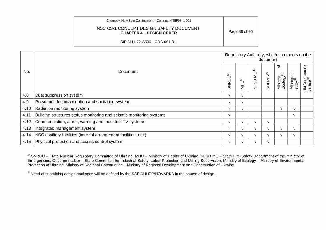
Chernobyl New Safe Confinement – Contract N° SIP08- 1-001
NSC CS-1 CONCEPT DESIGN SAFETY DOCUMENT CHAPTER 4 – DESIGN ORDER
SIP-N-LI-22-A500_-CDS-001-01
Page 88 of 96
Regulatory Authority, which comments on the
document
No. Document
SN
RC
U(1
)
MH
U(1
)
NF
SD
ME
(1)
SD
I MIS
(1)
Min
istr
y of
E
colo
gy(1
)
Min
regi
on-
stro
y(1)
Ukr
Der
zhbu
dex
pert
ise(1
)
4.8 Dust suppression system √ √
4.9 Personnel decontamination and sanitation system √ √
4.10 Radiation monitoring system √ √ √ √
4.11 Building structures status monitoring and seismic monitoring systems √ √
4.12 Communication, alarm, warning and industrial TV systems √ √ √ √
4.13 Integrated management system √ √ √ √ √ √
4.14 NSC auxiliary facilities (internal arrangement facilities, etc.) √ √ √ √ √ √
4.15 Physical protection and access control system √ √ √ √ 1) SNRCU – State Nuclear Regulatory Committee of Ukraine, MHU – Ministry of Health of Ukraine, SFSD ME – State Fire Safety Department of the Ministry of Emergencies, Gospromnadzor – State Committee for Industrial Safety, Labor Protection and Mining Supervision, Ministry of Ecology – Ministry of Environmental Protection of Ukraine, Ministry of Regional Construction – Ministry of Regional Development and Construction of Ukraine. 2) Need of submitting design packages will be defined by the SSE CHNPP/NOVARKA in the course of design.
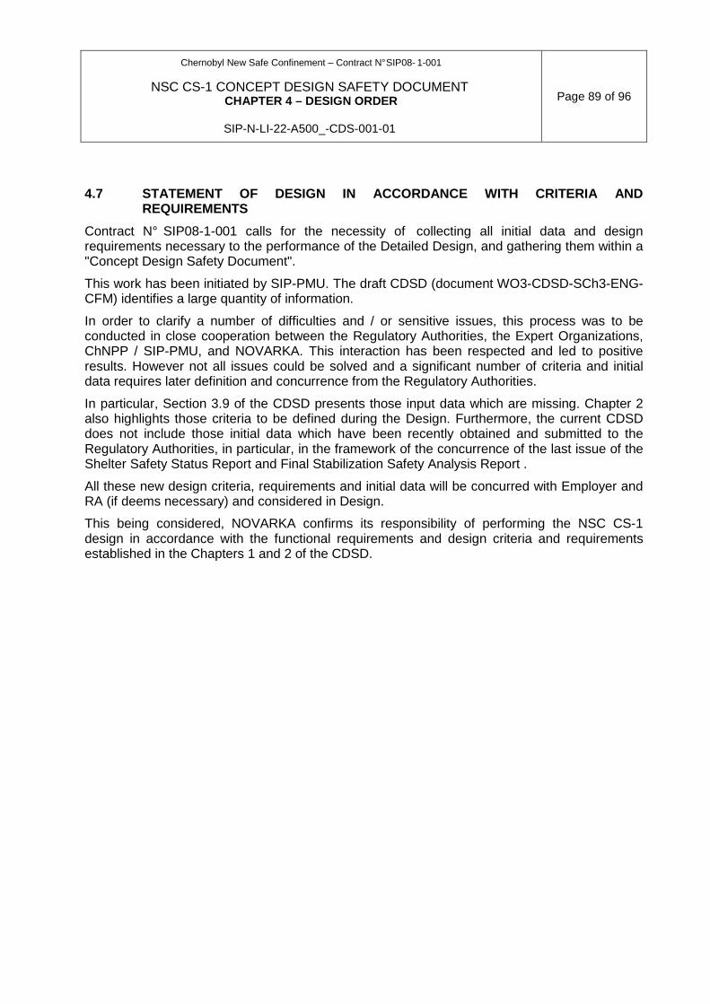
Chernobyl New Safe Confinement – Contract N° SIP08- 1-001
NSC CS-1 CONCEPT DESIGN SAFETY DOCUMENT CHAPTER 4 – DESIGN ORDER
SIP-N-LI-22-A500_-CDS-001-01
Page 89 of 96
4.7 STATEMENT OF DESIGN IN ACCORDANCE WITH CRITERIA AND REQUIREMENTS
Contract N° SIP08-1-001 calls for the necessity of collecting all initial data and design requirements necessary to the performance of the Detailed Design, and gathering them within a "Concept Design Safety Document".
This work has been initiated by SIP-PMU. The draft CDSD (document WO3-CDSD-SCh3-ENG-CFM) identifies a large quantity of information.
In order to clarify a number of difficulties and / or sensitive issues, this process was to be conducted in close cooperation between the Regulatory Authorities, the Expert Organizations, ChNPP / SIP-PMU, and NOVARKA. This interaction has been respected and led to positive results. However not all issues could be solved and a significant number of criteria and initial data requires later definition and concurrence from the Regulatory Authorities.
In particular, Section 3.9 of the CDSD presents those input data which are missing. Chapter 2 also highlights those criteria to be defined during the Design. Furthermore, the current CDSD does not include those initial data which have been recently obtained and submitted to the Regulatory Authorities, in particular, in the framework of the concurrence of the last issue of the Shelter Safety Status Report and Final Stabilization Safety Analysis Report .
All these new design criteria, requirements and initial data will be concurred with Employer and RA (if deems necessary) and considered in Design.
This being considered, NOVARKA confirms its responsibility of performing the NSC CS-1 design in accordance with the functional requirements and design criteria and requirements established in the Chapters 1 and 2 of the CDSD.

Chernobyl New Safe Confinement – Contract N° SIP08- 1-001
NSC CS-1 CONCEPT DESIGN SAFETY DOCUMENT CHAPTER 4 – DESIGN ORDER
SIP-N-LI-22-A500_-CDS-001-01
Page 90 of 96
ATTACHMENTS TO CHAPTER 4
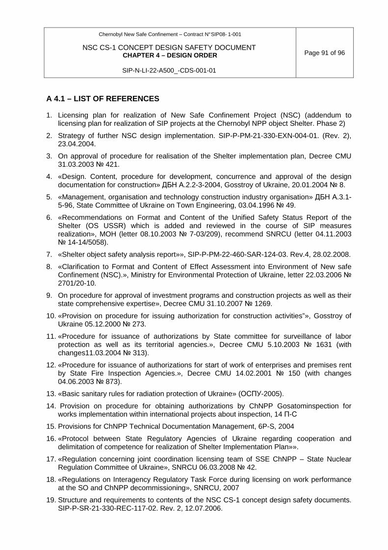
Chernobyl New Safe Confinement – Contract N° SIP08- 1-001
NSC CS-1 CONCEPT DESIGN SAFETY DOCUMENT CHAPTER 4 – DESIGN ORDER
SIP-N-LI-22-A500_-CDS-001-01
Page 91 of 96
A 4.1 – LIST OF REFERENCES
1. Licensing plan for realization of New Safe Confinement Project (NSC) (addendum to licensing plan for realization of SIP projects at the Chernobyl NPP object Shelter. Phase 2)
2. Strategy of further NSC design implementation. SIP-P-PM-21-330-EXN-004-01. (Rev. 2), 23.04.2004.
3. On approval of procedure for realisation of the Shelter implementation plan, Decree CMU 31.03.2003 № 421.
4. «Design. Content, procedure for development, concurrence and approval of the design documentation for construction» ДБН А.2.2-3-2004, Gosstroy of Ukraine, 20.01.2004 № 8.
5. «Management, organisation and technology construction industry organisation» ДБН А.3.1-5-96, State Committee of Ukraine on Town Engineering, 03.04.1996 № 49.
6. «Recommendations on Format and Content of the Unified Safety Status Report of the Shelter (OS USSR) which is added and reviewed in the course of SIP measures realization», MOH (letter 08.10.2003 № 7-03/209), recommend SNRCU (letter 04.11.2003 № 14-14/5058).
7. «Shelter object safety analysis report»», SIP-P-PM-22-460-SAR-124-03. Rev.4, 28.02.2008.
8. «Clarification to Format and Content of Effect Assessment into Environment of New safe Confinement (NSC).», Ministry for Environmental Protection of Ukraine, letter 22.03.2006 № 2701/20-10.
9. On procedure for approval of investment programs and construction projects as well as their state comprehensive expertise», Decree CMU 31.10.2007 № 1269.
10. «Provision on procedure for issuing authorization for construction activities”», Gosstroy of Ukraine 05.12.2000 № 273.
11. «Procedure for issuance of authorizations by State committee for surveillance of labor protection as well as its territorial agencies.», Decree CMU 5.10.2003 № 1631 (with changes11.03.2004 № 313).
12. «Procedure for issuance of authorizations for start of work of enterprises and premises rent by State Fire Inspection Agencies.», Decree CMU 14.02.2001 № 150 (with changes 04.06.2003 № 873).
13. «Basic sanitary rules for radiation protection of Ukraine» (ОСПУ-2005).
14. Provision on procedure for obtaining authorizations by ChNPP Gosatominspection for works implementation within international projects about inspection, 14 П-С
15. Provisions for ChNPP Technical Documentation Management, 6P-S, 2004
16. «Protocol between State Regulatory Agencies of Ukraine regarding cooperation and delimitation of competence for realization of Shelter Implementation Plan»».
17. «Regulation concerning joint coordination licensing team of SSE ChNPP – State Nuclear Regulation Committee of Ukraine», SNRCU 06.03.2008 № 42.
18. «Regulations on Interagency Regulatory Task Force during licensing on work performance at the SO and ChNPP decommissioning», SNRCU, 2007
19. Structure and requirements to contents of the NSC CS-1 concept design safety documents. SIP-P-SR-21-330-REC-117-02. Rev. 2, 12.07.2006.

Chernobyl New Safe Confinement – Contract N° SIP08- 1-001
NSC CS-1 CONCEPT DESIGN SAFETY DOCUMENT CHAPTER 4 – DESIGN ORDER
SIP-N-LI-22-A500_-CDS-001-01
Page 92 of 96
20. «Explanations on granting at early design stages NSC CS-1 in design sets the information
on safety».
21. «Explanation to format and content of NSC safety analysis report»,SNRCU, letter 03.05.2006 № 24-17/2404.
22. «Explanation to format and content of NSC sanitary compliance report with the requirements of state sanitary legislation», MOH, letter 20.03.2006 № 7.04/86.
23. «Proposition on advanced building of temporary foundations for sliding ways NSC and on arrangement of mounting site for enlarged assemblage of arched construction».
24. “Procedure for Development, Formatting, Statement, Legalization, Concurrence, Agreement, Indication and Registration of Technical Conditions” (DSTU 1.3-2004.)
25. “System to ensure reliability and safety of construction facilities - Scientific and engineering support for construction facilities”, MinRegionStroy of Ukraine, DBN V 1.2-5.2007
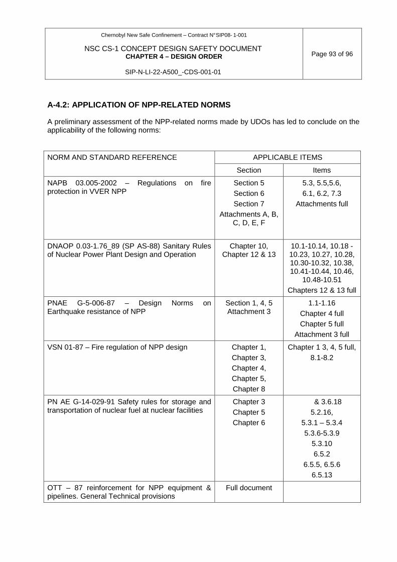
Chernobyl New Safe Confinement – Contract N° SIP08- 1-001
NSC CS-1 CONCEPT DESIGN SAFETY DOCUMENT CHAPTER 4 – DESIGN ORDER
SIP-N-LI-22-A500_-CDS-001-01
Page 93 of 96
A-4.2: APPLICATION OF NPP-RELATED NORMS
A preliminary assessment of the NPP-related norms made by UDOs has led to conclude on the applicability of the following norms:
APPLICABLE ITEMS NORM AND STANDARD REFERENCE
Section Items
NAPB 03.005-2002 – Regulations on fire protection in VVER NPP
Section 5 Section 6 Section 7
Attachments A, B, C, D, E, F
5.3, 5.5,5.6, 6.1, 6.2, 7.3
Attachments full
DNAOP 0.03-1.76_89 (SP AS-88) Sanitary Rules of Nuclear Power Plant Design and Operation
Chapter 10, Chapter 12 & 13
10.1-10.14, 10.18 - 10.23, 10.27, 10.28, 10.30-10.32, 10.38, 10.41-10.44, 10.46,
10.48-10.51 Chapters 12 & 13 full
PNAE G-5-006-87 – Design Norms on Earthquake resistance of NPP
Section 1, 4, 5 Attachment 3
1.1-1.16 Chapter 4 full Chapter 5 full
Attachment 3 full
VSN 01-87 – Fire regulation of NPP design Chapter 1, Chapter 3, Chapter 4, Chapter 5, Chapter 8
Chapter 1 3, 4, 5 full, 8.1-8.2
PN AE G-14-029-91 Safety rules for storage and transportation of nuclear fuel at nuclear facilities
Chapter 3 Chapter 5 Chapter 6
& 3.6.18 5.2.16,
5.3.1 – 5.3.4 5.3.6-5.3.9
5.3.10 6.5.2
6.5.5, 6.5.6 6.5.13
OTT – 87 reinforcement for NPP equipment & pipelines. General Technical provisions
Full document
Chernobyl New Safe Confinement – Contract N° SIP08- 1-001
NSC CS-1 CONCEPT DESIGN SAFETY DOCUMENT CHAPTER 4 – DESIGN ORDER
SIP-N-LI-22-A500_-CDS-001-01
Page 94 of 96
A-4.3. RECONCILIATION OF WESTERN NORMS
The standard and code reconciliation process is presented here for the NSC steel structures.
The preliminary design is developed by NOVARKA on the basis of European standards EUROCODES. The check for compliance with Ukrainian standards is being carried out by URDISC.
The basis of methodological approach is presented as follows:
• Both design organizations follow the standard logic of normative checking through reconciliation of Eurocodes on the one hand, and Ukrainian codes on the other hand
• Elementary load cases are retained with the factors applicable in the two codes and then internal forces are reconciled on the two models, where the reconciliation criterion is a fulfilment of strength conditions under the applicable codes. In case of difference in results a conservative solution is made.
• If Ukrainian codes are not available and a Eurocode gives some recommendations, the latter is used (e.g. calculation of nodes)
• If there are no regulatory requirements (for example for some assembly calculations) the methodology reconciled between Novarka and URDISC is used.
URDISC is involved at various stages of reconciliation:
• Identification of applicable Ukrainian norms;
• Review of applicable loads, calculation methodology;
• Comparisons of the main results of control calculation (1 stage) to check the concurrence of design models;
• Review of steel structure specification for procurement of raw materials and manufacturing;
• Full review of calculation check results (2 stage) with Eurocodes and Ukrainian codes and selection of final design solutions;
• Preparation of licensing documentation for steel structure.
Loads and Actions
Elementary load cases are first compared in EUROCODES and Ukrainian norms.
It is also the case for Wind loads taking into account the results of wind tunnel test
Codes have been compared in term of wind pressure with equivalent return periods.
After analysis, an agreed value is considered by both designers.
Calculation codes used
A 3D model of the steel structure was provided by NOVARKA on HERCULES software. Numerical model transferred from NOVARKA to URDISC SCADSOFT software (Geometrical data for example) Softwares are comparable in terms of performance (type of elements, modules, etc…). For preliminary verification some comparisons are made on unitary load cases.
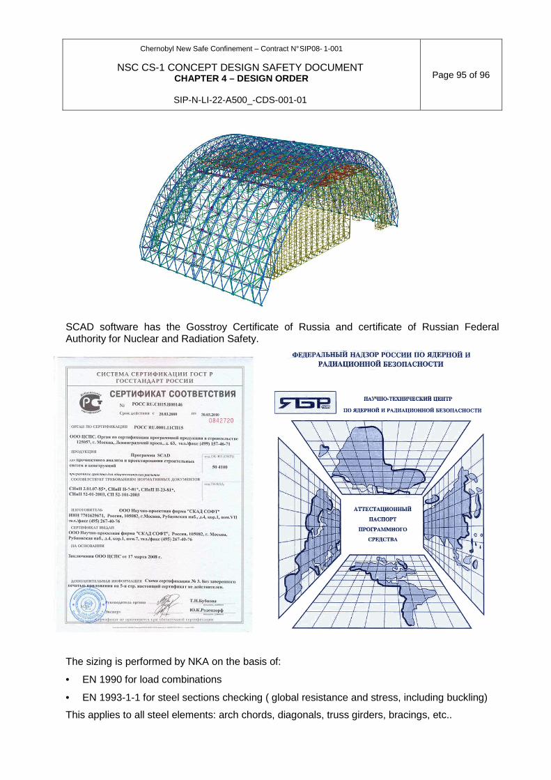
Chernobyl New Safe Confinement – Contract N° SIP08- 1-001
NSC CS-1 CONCEPT DESIGN SAFETY DOCUMENT CHAPTER 4 – DESIGN ORDER
SIP-N-LI-22-A500_-CDS-001-01
Page 95 of 96
SCAD software has the Gosstroy Certificate of Russia and certificate of Russian Federal Authority for Nuclear and Radiation Safety.
The sizing is performed by NKA on the basis of:
• EN 1990 for load combinations
• EN 1993-1-1 for steel sections checking ( global resistance and stress, including buckling)
This applies to all steel elements: arch chords, diagonals, truss girders, bracings, etc..

Chernobyl New Safe Confinement – Contract N° SIP08- 1-001
NSC CS-1 CONCEPT DESIGN SAFETY DOCUMENT CHAPTER 4 – DESIGN ORDER
SIP-N-LI-22-A500_-CDS-001-01
Page 96 of 96
URDISC finds the load combinations with reliability factors in accordance with DBN B. 1.2-2:2006 and will check the steel sections against SNIP II-23-81. The checking is performed for all elements of structure.
If the dimensioning of NKA is acceptable according to Ukrainian standards, the section is retained. If the section is not sufficient, URDISC will propose and justify another reinforced section (e.g HCS : same diameter but higher thickness ). The largest section from both options is used.
A synthetic global report is prepared by NKA/URDISC:
• Description of the process
• Discussion on the results ( explanation of differences)
• Final steel sections retained. Updating of drawings
This report is included in the final licensing documentation. The content and format will be agreed with the RA in advance


![a c arXiv:1701.08267v1 [astro-ph.EP] 28 Jan 2017 · cV.E. Zuev Institute of Atmospheric Optics, SB RAS, 1, Academician Zuev Square, Tomsk 634021, Russia ... and CDSD-296 databases](https://img.pdfslide.us/doc/110x75/5b9f135109d3f25b318c7f96/a-c-arxiv170108267v1-astro-phep-28-jan-2017-cve-zuev-institute-of-atmospheric.jpg)


![3. Seyda - ChNPP Site Remediation-flnal [Repaired]](https://img.pdfslide.us/doc/110x75/5852507c1a28abfa398d6280/3-seyda-chnpp-site-remediation-flnal-repaired.jpg)