Embed Size (px)
Citation preview

10ES-43 CONTROL SYSTEMS
( ECE ‘A B&C’ Section)
Faculty : Shreyus G & Prashanth V No of Hours:52
Class #
Chapter Title/
Reference
Literature
Topic to be covered
% of Portions covered
Reference
Chapter Cumulative
Part A
Unit 1: Modelling of Systems
1 T1 Ch 1.1, Mathematical models of physical
system.
15% 15%
2 T1 Ch 2.1
Differential equations of
physical –mechanical
systems.Friction, Translational
systems
3 T1 Ch 2.2 Rotational systems
4 T1 Ch 2.2 Gear trains
5 T1 Ch 2.7 Electrical systems
6 T1 Ch 2.7 Analogous systems
Unit 2:Block Diagrams and Signal Flow Graphs
7-10 T1 Ch 2.4,2.5 Transfer functions, Block
diagrams algebra 12% 27%
11-13 T1 Ch 2.6,2.7 Signal flow graphs;
Unit 3:Time response of feed back control systems
14-15 T1 Ch 5.1,5.2
Standard test signals ,unit step
response of first and second
order systems
15% 42% 16-17 T1 Ch 5.3 Time response specifications
18 T1 Ch 5.4 Time response specifications of
second order systems
19-20 T1 Ch 5.5 Steady state errorsand error
constants.
Unit 4:Stability analysis
21-22 T1 Ch 6.1,6.2 Concept of stability, Necessary
conditions for stability
20% 62% 23-24 T1 Ch 6.4,6.5 Routh-stability criterion
25-26 T1 Ch 6.6 More on the routh stability
criterion
Part B Unit 5:Root Locus Technique
27-28 T1 Ch 7.1 Introduction;
15% 77% 29-32 T1 Ch 7.2,7.3
Properties and construction of
the root loci; Problems
Unit 6: Stability in the Frequency Domain
33-34 T1 Ch 9.1 Mathematical preliminaries,
23% 100%
35-37 T1 Ch 9.2 Nyquest stability criterion
38-39 T1 Ch 9.3-9.4 Assessment of relative stability
using Nyquest criterion
Text Book:
1. J.Nagarath and M.Gopal, “ Control systems Engineering” New
AgeInternational (p) Limited,Publishers, 4th Edition-2005
Reference Books:
1.”Modern Control Engineering”, K.Ogata,Pearson Education
Asia/PHI, 4th Edition,2002 2. “Concepts of ControlSystems”,P.S. Satyanarayana: Dynaram
publishers,Bangalore,2001 3. “Control systems- Principaes and design”, M.Gopal,TMH.1999
4. “Feedback control system analysis and synthesis”,J.J.D’Azzo and C.H.Houpis;McGraw Hill,International student Edition.
Unit 6:Frequency domainanalysis
27-28 T1 Ch 7.1 Introduction;
15% 77% 29-32 T1 Ch 7.2,7.3
Properties and construction of
the root loci; Problems
Unit 8: Introduction to state variable analysis
33-34 T1 Ch 9.1 Mathematical preliminaries,
23% 100%
35-37 T1 Ch 9.2 Nyquest stability criterion
38-39 T1 Ch 9.3-9.4 Assessment of relative stability
using Nyquest criterion

Question Bank
Chapter 1: Modeling of Systems
1) What is control system? Explain different types of Control system.
2) What are the advantages and disadvantages of open loop and closed loop
system?
3) Explain the comparison between open loop and closed loop system.
(A) Electrical System
4) Find the Transfer function of the Electrical network system
..
5) Find the Transfer function of the Electrical network system
R1
Vi Vo
C R2
6) Find the Transfer function of the Electrical network system
7) Find the Transfer function of the Electrical network system
..
8) Determine the transfer function relation Vo(s) to Vi(s) for the network shown in fig
below. Calculate output voltage t≥0 for a unit step voltage input at t=0.

(B) Mechanical System
9) Write the mechanical network for the following mechanical system
X
K
f(t)
B
10) Write the mechanical network for the following mechanical system
K
D1
X2
D2
X1
f(t)
M
M1
M2
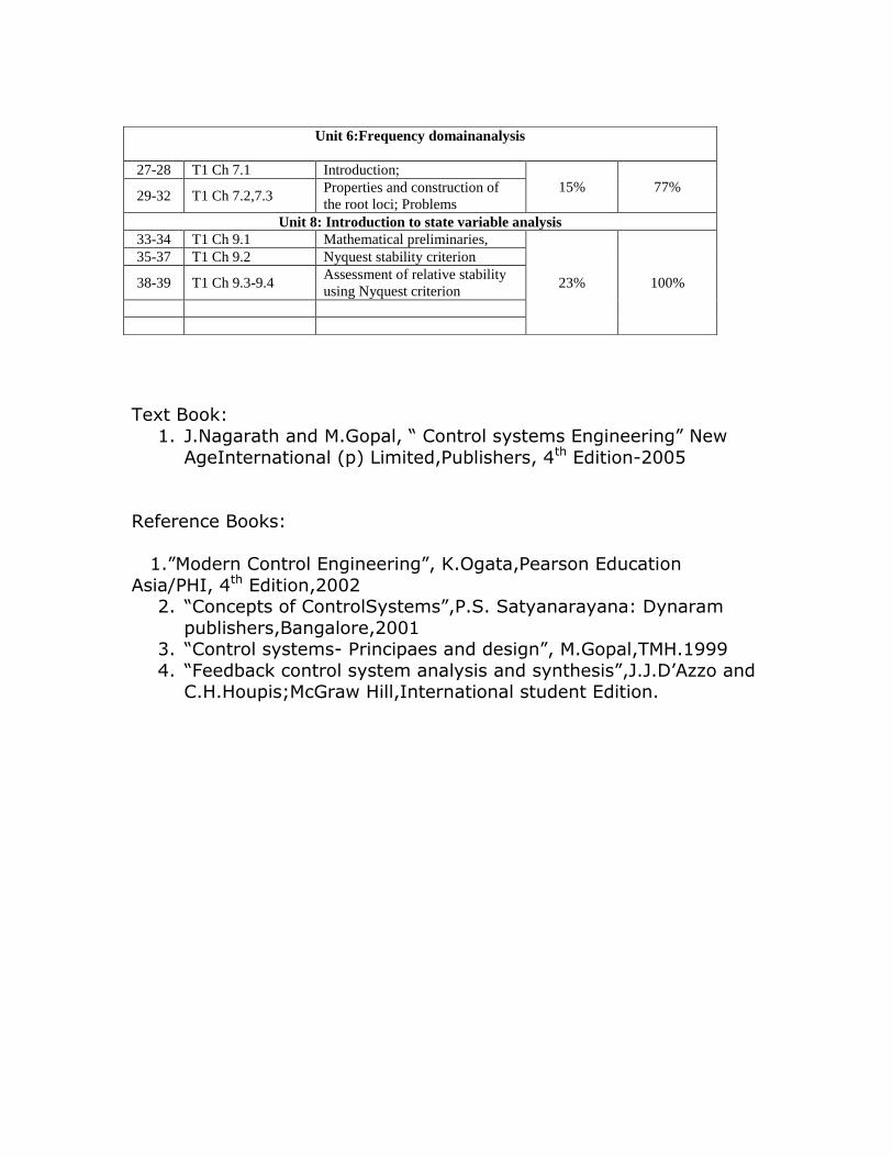
11) Write the mechanical network for the following mechanical system
B3 X2 Xo X1
K2 B2 f(t)
K3 K1
12) Write the differential equations governing the mechanical system show in fig. Find
T.F
X1 X
B
K1
f(t)
K
B1 B2
13) Determine the transfer function X1(s) F(s) and X2(s)/F(s) for the system shown in fig
below.
X1 X2
f(t)
K1 B12 K2
B1 B2
M2
M1
M1
M1
M1
M1

14) Obtain the Mechanical circuit for the following Mechanical system and Find
X1(s)/F(s)
D1 K1
B2
X1
K2
f(t) (C) Analogous System
15) For the Mechanical system given find a) Write the Differential equations
b) Draw the Mechanical network c) Draw the F-V and F-I analogous circuit
B3 X2 Xo X1
K2 B2 f(t)
K3 K1
16) For the Mechanical system given find a) write the Differential equations
b) Draw the Mechanical network c) Draw the F-V and F-I analogous circuit
K
D1
X2
D2
X1
M2
M1
M2
M1
M1
M2
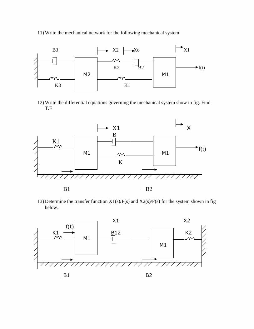
17) For the Mechanical system given find a) Write the Differential equations
b) Draw the Mechanical network c) Draw the F-V and F-I analogous circuit
B3
B1
f(t)
18) For the Mechanical system given find a) Write the Differential equations
b) Draw the Mechanical network c) Draw the F-V and F-I analogous circuit
X2 X3
K2 K3
B2 B3
X1 K1
f(t)
B1
M2
M1
M2 M3
M1
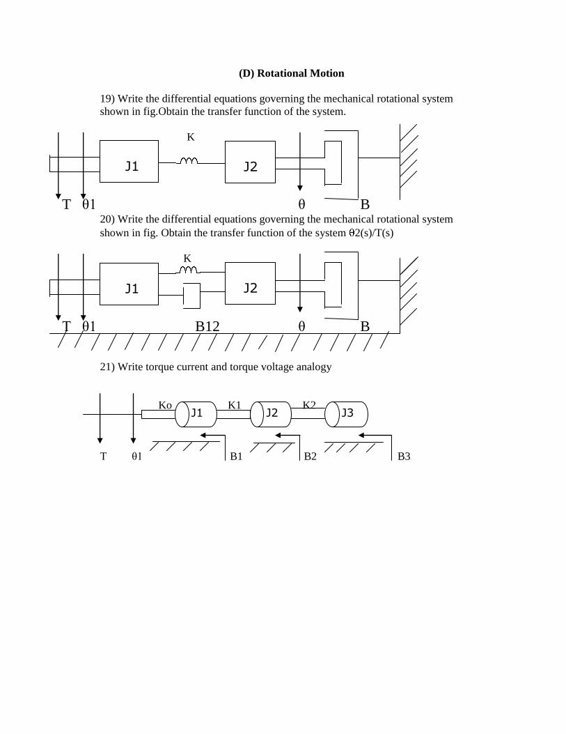
(D) Rotational Motion
19) Write the differential equations governing the mechanical rotational system
shown in fig.Obtain the transfer function of the system.
K
T θ1 θ B
20) Write the differential equations governing the mechanical rotational system
shown in fig. Obtain the transfer function of the system 2(s)/T(s)
K
T θ1 B12 θ B
21) Write torque current and torque voltage analogy
Ko K1 K2
T θ1 B1 B2 B3
J1
J2
J1
J2
J1 J2 J3
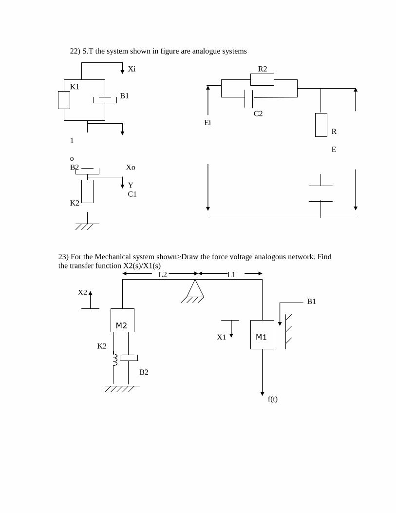
22) S.T the system shown in figure are analogue systems
Xi R2
K1
B1
C2
Ei
R
1
E
o
B2 Xo
Y
C1
K2
23) For the Mechanical system shown>Draw the force voltage analogous network. Find
the transfer function X2(s)/X1(s)
L2 L1
X2
B1
X1
K2
B2
f(t)
M2
M1
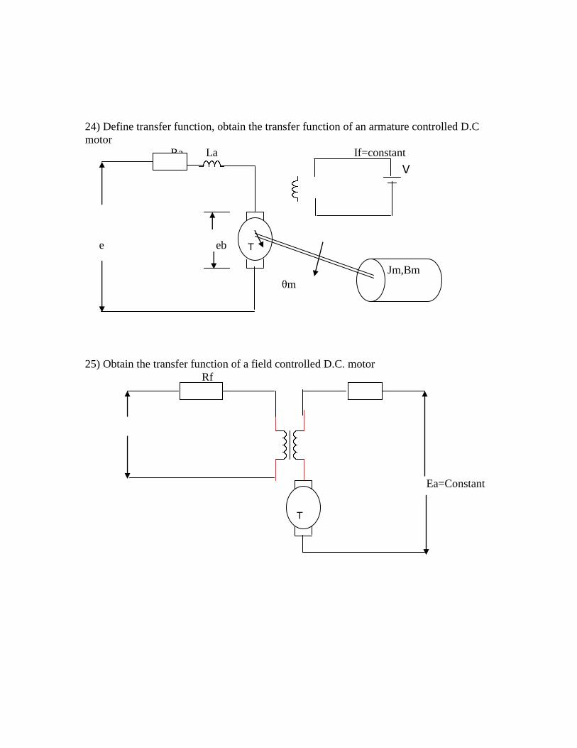
24) Define transfer function, obtain the transfer function of an armature controlled D.C
motor
Ra La If=constant
V
e eb
θm
25) Obtain the transfer function of a field controlled D.C. motor
Rf
Ea=Constant
T
m
T
m
Jm,Bm

Assignment question
1) If C=1 f in the circuit shown in fig what values of R1 and R2 will give T=0.6sec
and a=0.1
R1
Vi Vo T.F=a (1+ST)
C R2 1+aST
2) Find the Transfer function of the network shown in fig below
R i1 i2
Vi(t) C C Vo(t)
R
3) Write the differential equations for the electrical network shown
L1 R1 L2
i1(t) i2(t)
+
V C R2
-
4) Write the mechanical network for the following machine system
X3
K2 B1 X2 K1 X1
M2 f(t)
B2
M1
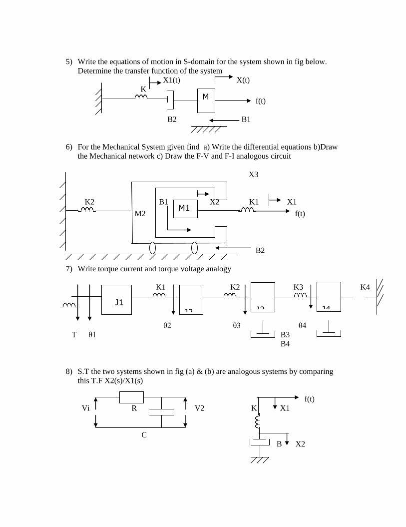
5) Write the equations of motion in S-domain for the system shown in fig below.
Determine the transfer function of the system
X1(t) X(t)
K
f(t)
B2 B1
6) For the Mechanical System given find a) Write the differential equations b)Draw
the Mechanical network c) Draw the F-V and F-I analogous circuit
X3
K2 B1 X2 K1 X1
M2 f(t)
B2
7) Write torque current and torque voltage analogy
K1 K2 K3 K4
θ2 θ3 θ4
T θ1 B3
B4
8) S.T the two systems shown in fig (a) & (b) are analogous systems by comparing
this T.F X2(s)/X1(s)
f(t)
Vi R V2 K X1
C
B X2
M
M1
J1
J2
J3
J4

9) Write torque current and torque voltage analogy
K K2
K1
θ3
T θ1 θ2 B
10) Draw the analogues circuit also Write the Differential equation for the Mechanical
system.
K
L1 f ‘(t) L2
f(t) X(t)
B
Chapter 2: Block diagram reduction and Signal floe graph
I) using block diagram reduction technique find closed loop transfer function of the
system
1)
G2
H1
H2
G1 G3
H3
J1
J2
M

2)
3)
4)
G2
G4
H1
G3
H2
G1
G2
H1
H2
G3
G4
G1
G2
H3
H1 H2
G1
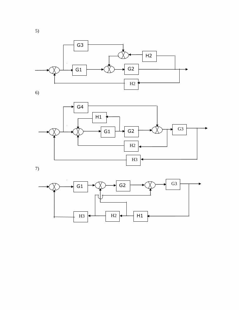
5)
6)
7)
G2
H2 H1
G1 G3
H3
G2
H2
G4
H1
G1 G3
H3
G2
H2
G3
H2
G1
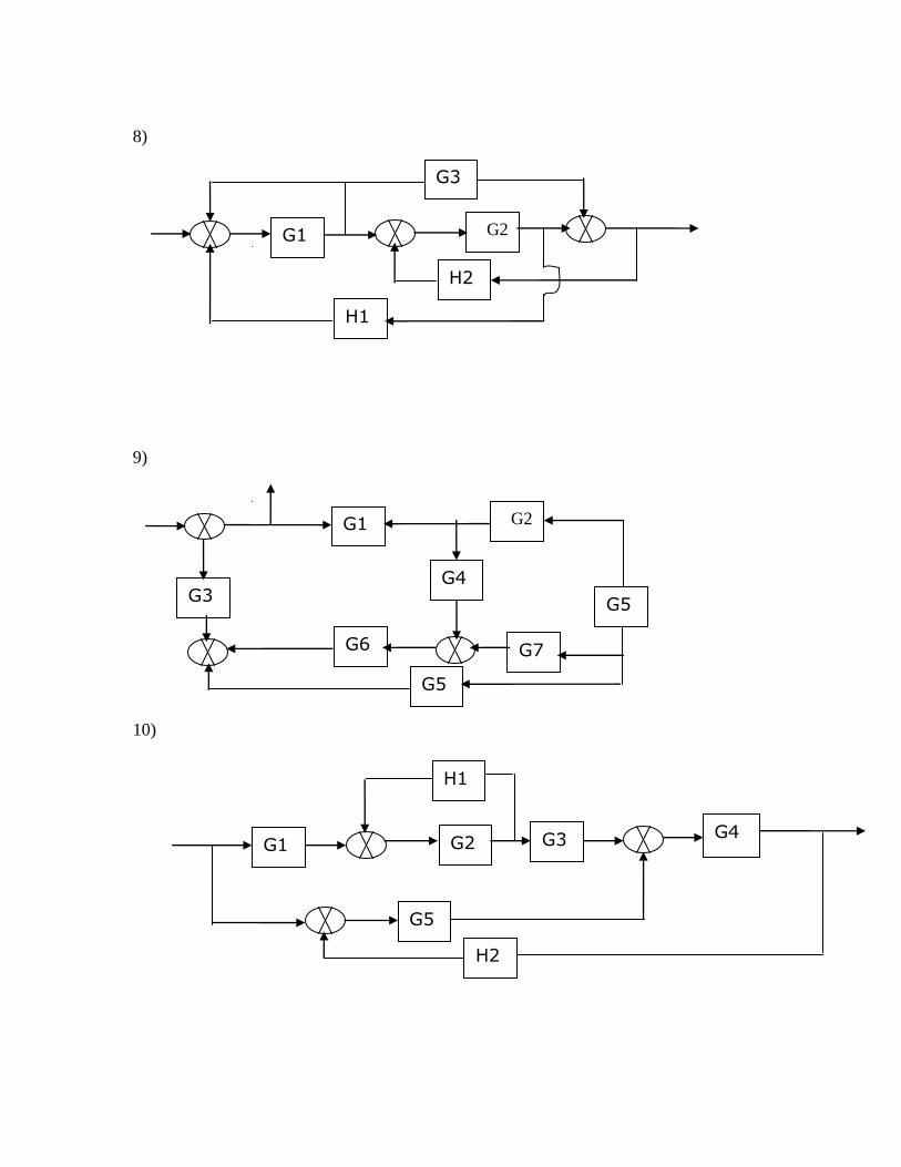
8)
9)
10)
G1 G2
G5
G4 G3
H2
H1
G7
G1 G2
G5
G4 G3
G6
G5
G1 G2
G3
H1
H2
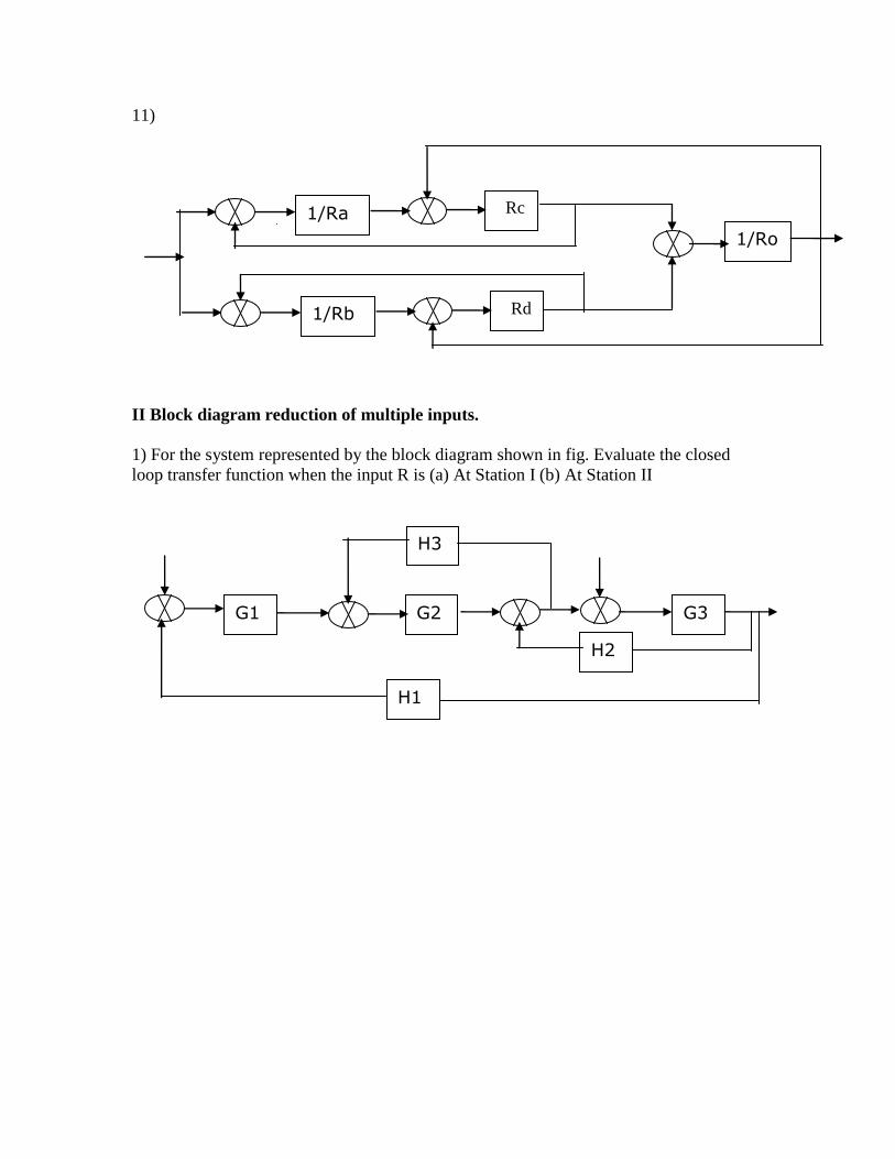
11)
II Block diagram reduction of multiple inputs.
1) For the system represented by the block diagram shown in fig. Evaluate the closed
loop transfer function when the input R is (a) At Station I (b) At Station II
G1 G2 G3
H1
H2
H3
1/Ra Rc
1/Ro
1/Rb Rd

2) Find the transfer function C1/R1 and C2/R2
+ - R1 + C1
+
+ +
R2 C
2
+ -
3) A multi-input and multi output system is shown in fig determine the following transfer
function
C1/R1 when R2=0 , C2/R1 when R2=0 , C1/R2 when R1=0 and C2/R2 when R1=0
+ C1
R1
-
-
R2 - + R2
G1
G2
G3
G4
G1 G3
H2 H1
G6
G2
G5
G4
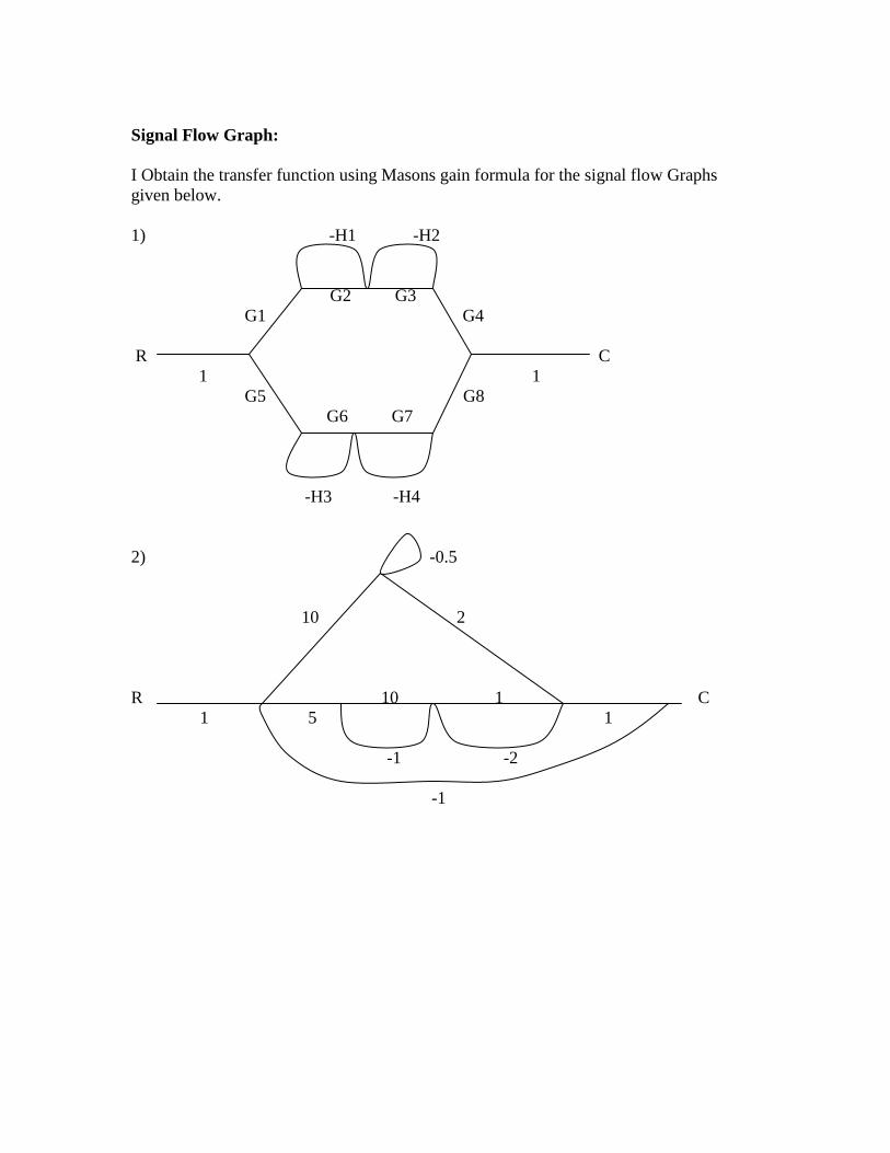
Signal Flow Graph:
I Obtain the transfer function using Masons gain formula for the signal flow Graphs
given below.
1) -H1 -H2
G2 G3
G1 G4
R C
1 1
G5 G8
G6 G7
-H3 -H4
2) -0.5
10 2
R 10 1 C
1 5 1
-1 -2
-1

3)
-H1
G4
G2 G1 G8 G6
R(s) 1 1 C(s)
G3 G7
G5
-H2
4) -H1
0.5
R(s) G2 G3 G4
C(s)
-H2 G6
-H3
5)
-H2
1 G1 G2 G3 G4
R(s) C(s)
-H1
-1
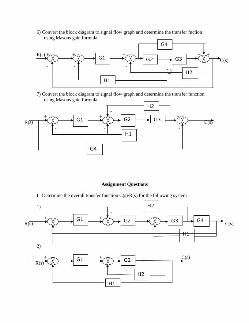
6) Convert the block diagram to signal flow graph and determine the transfer fnction
using Masons gain formula
R(s) + + + + +
C(s)
- - -
7) Convert the block diagram to signal flow graph and determine the transfer function
using Masons gain formula
-
+ + +
R(s) C(s)
- - -
Assignment Questions
I Determine the overall transfer function C(s)/R(s) for the following system
1)
-
+ + +
R(s) C(s)
2)
+ + C(s)
R(s)
-
G1
G2 G3
G4
H2
H1
G1
G2 G3
H2
G4
H1
G1
G2 G3
H2
G4
H1
G1
G2
H1
H2

3)
C(s)
+ + + +
R(s)
- +
4)
+
R(s) +
C(s)
+
-
+
Chapter 3: Time domain Analysis of Control System
1)For a second order system subjected to unit step input ,determine tr,tp,Mp and settling
time ts given ζ=0.6 wn=5 r/s
2) A unity feed back control system is characterized by an open-loop transfer function
G(s) H(s) = K
S(S+10)
Determine the gain K,so that the system will have a damping ratio of 0.5.For this value of
K find the rise time, peak time and peak overshoot. Assume that the system is subjected
to a step of 1V.
G1
G2 G3
H1
G4
H2
H3
H4
H2
G2 G1
H1
G4
G4
H3
3) The open loop transfer function of a unity feedback system is given by G(s) = K
S (ST+1)
where K & T are +ve constant. By what factor should the amplifier gain K be reduced, so
that the peak overshoot of unit step response of the system is reduced from 75% to 25%.
4) A unity feedback control system has an open loop transfer function G(s) = 10
Find the rise time, S(S+2)
percentage overshoot, peak time and settling time for a step input of 12 units.
5) Measurements conducted an a servomechanism show the system response to be
C(t)=1+0.2e-60t
-1.2e—10t
when subjected to a unit step input. Obtain an expression for
closed loop transfer function, Determine the undamped natural frequency and damping
ratio.
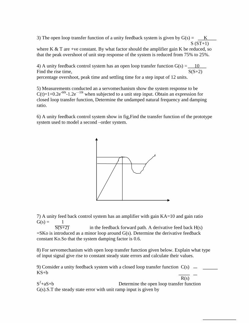
6) A unity feedback control system show in fig,Find the transfer function of the prototype
system used to model a second –order system.
7) A unity feed back control system has an amplifier with gain KA=10 and gain ratio
G(s) = 1
S(S+2) in the feedback forward path. A derivative feed back H(s)
=SKo is introduced as a minor loop around G(s). Determine the derivative feedback
constant Ko.So that the system damping factor is 0.6.
8) For servomechanism with open loop transfer function given below. Explain what type
of input signal give rise to constant steady state errors and calculate their values.
9) Consider a unity feedback system with a closed loop transfer function C(s)
KS+b
R(s)
S2+aS+b Determine the open loop transfer function
G(s).S.T the steady state error with unit ramp input is given by

a-K
b
10) A unity feedback system has the forward transfer function G(s) = K1 (2S+1) The
input r(t)=1+6t is
S (5S+1) (1+S2)
applied to the systems. Determine the minimum values of K1 if the steady error is to be
less than 0.1
11) For a control system the open loop transfer function is G(s) = 40
Determine the steady
(S+1) (S2
+10S+6))
state error of the system. When the transfer function of the feed back path is H(s) = 4
(S+3) and the system input are (i) r(t)=4U(t) (ii)=5tU(t) (iii)
r(t)= t2/2
12) For the unity feed back system shown in fig find the steady state error for (i) a unit
step input (ii) a unit step velocity input (iii) a unit step acceleration input
13) A unity feed back Has G(s) = 40 (S+2)
S(S+1) (S+4)
Determine (i) Type of the system
(ii) Steady state error for the input r (t) = 4t
14) For a unity system G(s) = 100 r(t)=6t. Determine steady state errors.
S(S+8)
If it is desired to reduce this existing error by 5%. Find new value of gain of the system.
Assignment:
1) A unity feedback control system is characterized by the following open loop transfer
function
G(s) = 0.4S+1 Determine its transient response for unit step input and sketch the
response,
S(S+0.6)
Evaluate the maximum overshoot and the corresponding peak time.
10
0.2S+1
0.5S+1
20
0.4
S2+3S+4

2) For system shown in fig determine i) Wn ii) Wd iii) damping ratio ζ iv) rise time tr
v) % peak overshoot approximate 5% settling time vi) input to the system may be
assumed to be step input signal
R(s) C(s)
3) For the system shown below determine the value of K,Kh,Mp is 20% tp=1 sec. Obtain
tr & ts
R(s) C(s)
4) A unity feed back system has G(s)= 80 (S+1) Determine (i) Type of the system
(ii) All error
S(S+2)(S+4)
Coefficients and (iii) Steady state errors for a ramp input r(t)=4t.
5) For the unity feedback system having open loop transfer function G(s)= K(S+1)
S (S3+5 S
2+6S)
Determine (i)Type of the system (ii) error constants (iii) Steady state error for unit
parabolic input
9
S(S+3)
K
S(S+1)
1+Kh
S
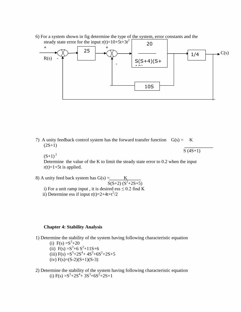
6) For a system shown in fig determine the type of the system, error constants and the
steady state error for the input r(t)=10+5t+3t2
+ +
C(s)
R(s) -
-
7) A unity feedback control system has the forward transfer function G(s) = K
(2S+1)
S (4S+1)
(S+1) 2
Determine the value of the K to limit the steady state error to 0.2 when the input
r(t)=1+5t is applied.
8) A unity feed back system has G(s) = K
S(S+2) (S2+2S+5)
i) For a unit ramp input , it is desired ess ≤ 0.2 find K
ii) Determine ess if input r(t)=2+4t+t2/2
Chapter 4: Stability Analysis
1) Determine the stability of the system having following characteristic equation
(i) F(s) =S3+20
(ii) F(s) =S3+6 S
2+11S+6
(iii) F(s) =S5+2S
4+ 4S
3+6S
2+2S+5
(iv) F(s)=(S-2)(S+1)(S-3)
2) Determine the stability of the system having following characteristic equation
(i) F(s) =S5+2S
4+ 3S
3+6S
2+2S+1
20
S(S+4)(S+10)
10S
1/4 25

(ii) F(s) =S5+S
4+ 2S
3+2S
2+3S+5
3) Determine the stability of the system having following characteristic equation
(i) F(s) =S8+5S
6+ 2S
4+3S
2+1
(ii) F(s) =S5+S
4+ 4S
3+24S
2+3S+63
(iii) F(s) =S6+2S
5+ 8S
4+12S
3+20S
2+16S+16
(ii) F(s) =S5+2S
4+ 24S
3+48S
2-25S-50
4) Find the range of K so that the system has the G(s)= K & H(s)=1
S (S2+S+1) (S+4)
and the system will be stable.
5) A unity feed back system having 2 is marginally stable and
S (S2+PS+4K)
oscillates with frequency 2 r/s. Find K & P
6) An open loop transfer function has poles at S=0 & S=-2 and zero at S=-4 if H=1
.Determine the range of K for stable system.
7) Find how many roots have real parts greater than -1 for S3+9 S
2+30S+40=0
8) An unity feed back control system has open loop transfer function G(s) = K
S(1+T1S) (1+T2S)
Find the value of K, if the system is stable (T1 & T2>0)
9) Determine the range of K such that the roots of the characteristic equation
F(s)=S(S+1)(S2+3S+2)+K=0 are more negative than -1
10) Find the range of K for stable feed back control system show in fig
11) A system oscillates with a frequency of W, if it has poles at S=±jW and no poles in
the right half of S- plane. Determine the values of K and a . So that the system
shown in fig oscillates at a frequency of 2 r/s
5/
S
5S+10
S+1
K
S+1

12) For a unity feed back system with G(s) = K using RH criterion find
the range
S(1+0.4S) (1+0.25S)
of K for stability, marginal value of K and frequency of sustained
oscillations.
Assignment:
1) Determine the stability of the system having following characteristic equation
(i) F(s) =S4+20S
3+55S
2+60S+34
(ii) F(s) = S4+4S
3+3S
2+10S+20
(iii) F(s) =S5+2S
4+3S
3+6S
2+5S+6
(iv) F(s)= S4+2S
3+6S
2+8S+8
2) For the closed loop feedback system G(s) = K Determine the range of
K for which the
S4+5S
3+5S
2+4S+K
system is stable and also the frequency of the sustained oscillation.
3) A unity feed back control system has G(s) = K(S+13) using the Routh’s
Criterion calculate the
S(S+3) (S+7)
range of K for which the system is (i) stable (ii) has its closed loop poles more
negative than -1
4) A unity feed back control system has G(s) = K using the Routh’s
Criterion, find the range of
S(S+2) (S+4) (S+6)
K for stability. Also find Kmax & Wmax.
5) For the system represented by open loop transfer function G(s) H(s) = K
using RH criterion
(S+1) (S+2)
(S+3)
(i) Determine the range of K for which the system is stable. (ii) The value of K for
which the system develops a sustained sinusoidal oscillations and corresponding
frequency.
K(S+1)
S3+aS2+2S+1

Chapter 5: Root Locus
1) A unity feed back control system has the forward transfer G(s) = K
(S+2)(S+4)
2) Plot the root locus pattern of a system whose forward path transfer function is G(s) =
K
S(S+2) (S+3)
3) A negative feed back control system is characterized by G(s) H(s) = K
S(S+1) (S+2)
(S+3)
Sketch the root locus plot for values of K ranging from 0 to ∞.Mark all the salient
points on the root locus.
4) A unity feed back control system has G(s) = K Sketch the root locus has
show on it
S(S+2) (S+5)
(a) Breakaway point (b) line for ζ=0.5 and value of K for this damping ratio (c) The
frequency at which the root locus crosses the imaginary axis and the corresponding
values of K.
5) Sketch the root locus plot for a negative feed back control system having an open
loop transfer function
G(s) H(s) = K
S(S2+2S+2)
6) Sketch the root locus plot for unity feed back control system having an open loop
transfer function
G(s) H(s) = K
S (S+4) (S2+4S+20)
7) For a system having loop transfer function G(s) H(s) = K Plot the
root locus and find
(S+3) (S2+4S+3)
the values of K for marginal stability and corresponding frequency of oscillations.

8) Sketch the root locus of a feed back control system whose open loop transfer function
is given by
G(s) H(s) = K Determine the value of K for damping ratio ζ
=0.5
S (S+3) (S2+2S+2)
9) Sketch the root locus of a feed back control system whose open loop transfer function
is given by
G(s) = K(S+4) and H(s) =1. Determine the value of K for damping ratio ζ
=0.707
S (S2+16S+13)
10) Sketch the root locus for positive values of K for the system G(s)H(s)= K(S+6)
S(S+1) (S+2)
Indicate all salient points and determine the range of K for which the system is stable
also find the K value at BAP.
11) Sketch the root locus plot for a closed loop system having an open loop transfer
function G(s) = K(S+2)
S(S+1)
For all values of K from 0 to ∞. Comment on the stability of the system. Also show
that a part of the root locus is a circle.
13) Sketch the root locus for a unity feed back control system with open loop transfer
function
G(s) = K(S+1) (S+3)
S(S+1)
K1
S+1
K2
S+3
K4
S+4
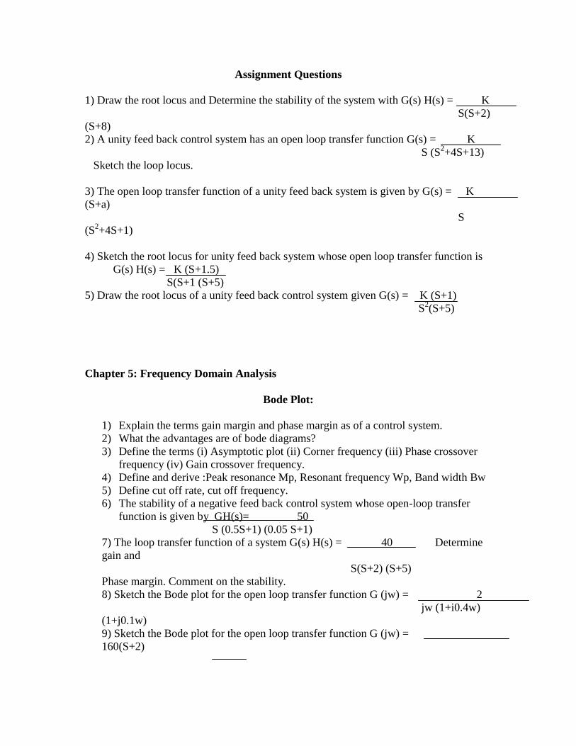
Assignment Questions
1) Draw the root locus and Determine the stability of the system with G(s) H(s) = K
S(S+2)
(S+8)
2) A unity feed back control system has an open loop transfer function G(s) = K
S (S2+4S+13)
Sketch the loop locus.
3) The open loop transfer function of a unity feed back system is given by G(s) = K
(S+a)
S
(S2+4S+1)
4) Sketch the root locus for unity feed back system whose open loop transfer function is
G(s) H(s) = K (S+1.5)
S(S+1 (S+5)
5) Draw the root locus of a unity feed back control system given G(s) = K (S+1)
S2(S+5)
Chapter 5: Frequency Domain Analysis
Bode Plot:
1) Explain the terms gain margin and phase margin as of a control system.
2) What the advantages are of bode diagrams?
3) Define the terms (i) Asymptotic plot (ii) Corner frequency (iii) Phase crossover
frequency (iv) Gain crossover frequency.
4) Define and derive :Peak resonance Mp, Resonant frequency Wp, Band width Bw
5) Define cut off rate, cut off frequency.
6) The stability of a negative feed back control system whose open-loop transfer
function is given by GH(s)= 50
S (0.5S+1) (0.05 S+1)
7) The loop transfer function of a system G(s) H(s) = 40 Determine
gain and
S(S+2) (S+5)
Phase margin. Comment on the stability.
8) Sketch the Bode plot for the open loop transfer function G (jw) = 2
jw (1+i0.4w)
(1+j0.1w)
9) Sketch the Bode plot for the open loop transfer function G (jw) =
160(S+2)
S2 (S+8)
(S+10)
10) Construct Bode Magnitude and phase diagrams GH(s) = 100 (0.1S+1)
S(S+1)2 (0.01S+1)
Also comment on the stability of the system
11) Construct Bode Magnitude and phase diagrams GH(s) = 200 (S+2)
S (S2 +10S+100)
Also comment on the stability of the system
12) Construct Bode Magnitude and phase diagrams GH(s) = 64 (S+2)
S (S2+3.2S+64) (S+0.5)
Also comment on the stability of the system
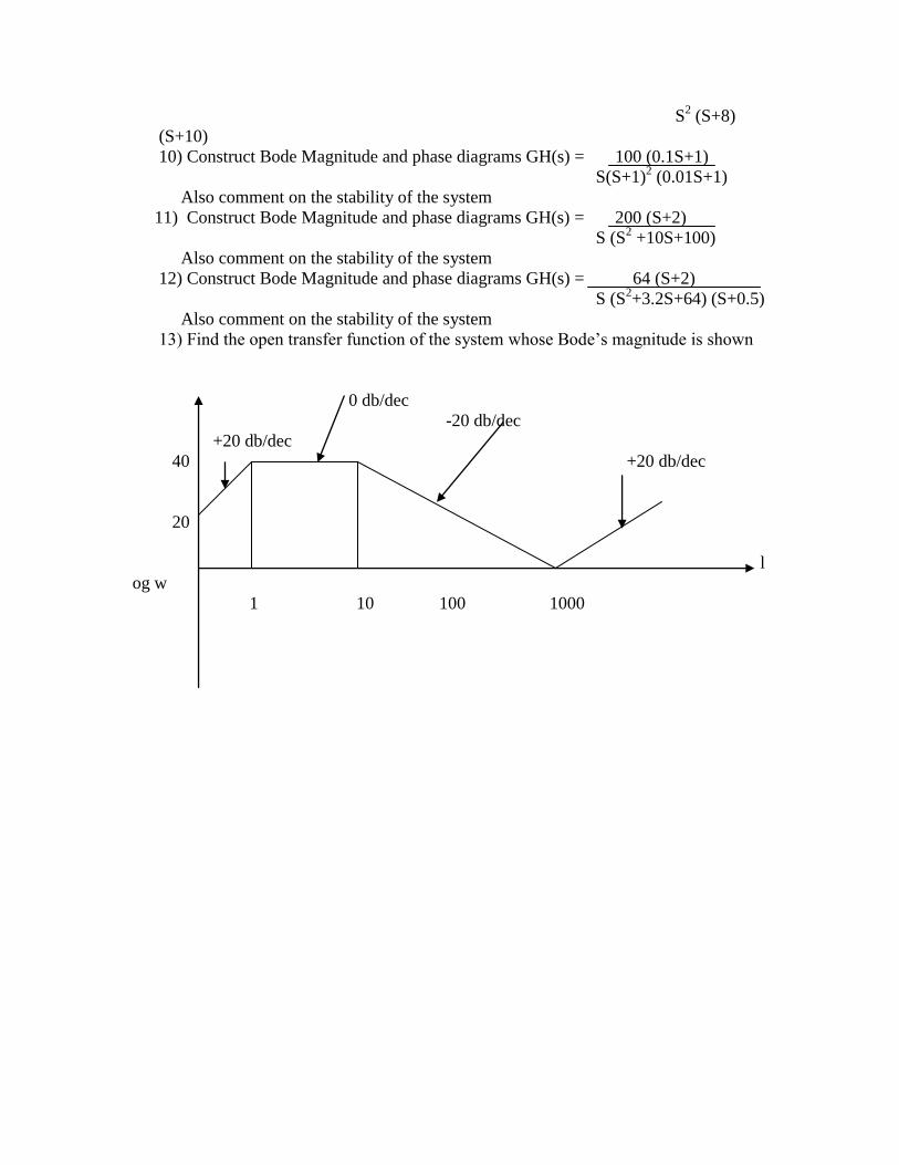
13) Find the open transfer function of the system whose Bode’s magnitude is shown
0 db/dec
-20 db/dec
+20 db/dec
40 +20 db/dec
20
l
og w
1 10 100 1000
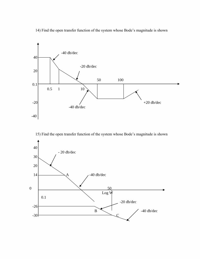
14) Find the open transfer function of the system whose Bode’s magnitude is shown
-40 db/dec
40
-20 db/dec
20
50 100
0.1
0.5 1 10
-20 +20 db/dec
-40 db/dec
-40
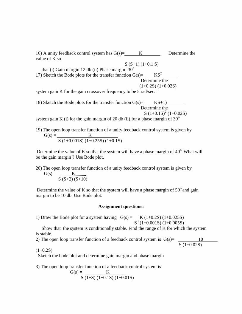
15) Find the open transfer function of the system whose Bode’s magnitude is shown
40
- 20 db/dec
30
20
14 A -40 db/dec
0 50
Log W
0.1
-20 db/dec
-26
B -40 db/dec
-30 C
16) A unity feedback control system has G(s)= K Determine the
value of K so
S (S+1) (1+0.1 S)
that (i) Gain margin 12 db (ii) Phase margin=30o
17) Sketch the Bode plots for the transfer function G(s)= KS2
Determine the
(1+0.2S) (1+0.02S)
system gain K for the gain crossover frequency to be 5 rad/sec.
18) Sketch the Bode plots for the transfer function G(s)= KS+1)
Determine the
S (1+0.1S)2 (1+0.02S)
system gain K (i) for the gain margin of 20 db (ii) for a phase margin of 30o
19) The open loop transfer function of a unity feedback control system is given by
G(s) = K
S (1+0.001S) (1+0.25S) (1+0.1S)
Determine the value of K so that the system will have a phase margin of 40o .What will
be the gain margin ? Use Bode plot.
20) The open loop transfer function of a unity feedback control system is given by
G(s) = K
S (S+2) (S+10)
Determine the value of K so that the system will have a phase margin of 50o and gain
margin to be 10 db. Use Bode plot.
Assignment questions:
1) Draw the Bode plot for a system having G(s) = K (1+0.2S) (1+0.025S)
S3 (1+0.001S) (1+0.005S)
Show that the system is conditionally stable. Find the range of K for which the system
is stable.
2) The open loop transfer function of a feedback control system is G(s)= 10
S (1+0.02S)
(1+0.2S)
Sketch the bode plot and determine gain margin and phase margin
3) The open loop transfer function of a feedback control system is
G(s) = K
S (1+S) (1+0.1S) (1+0.01S)
Determine the value of K
4) The open loop transfer function of a feedback control system is G(s)= 242(S+5)
S (S+1) (S2
+5S+121)
Sketch the bode plot and determine gain margin and phase margin
Nyquist Path and Stability Criterion:
1) State and explain Nyquist stability criterion.
2) Define gain margin and phase margin and explain how you measure them using
Nyquist criterion
3) For the gain open loop transfer function G(s) H(s) = K of a system,
sketch the
S(S+2) (S+10)
Nyquist plot and calculate the range of K for the system to be stable.
4) For the gain open loop transfer function G(s) H(s) = K of a system,
sketch the
S(S+1) (S+2)
Nyquist plot and calculate the range of K for the system to be stable.
5) Find the range of values of K for which the closed loop control system is stable by
using Nyquist criterion. G(s) H(s) = K(S+1)
S(S-1)
6) Given that G(s) H(s) = K Determine the value of K for stability using Nyquist
analysis.
S(S+S2)
7) Sketch the Nyquist plot of a unity feedback control system having the open loop
transfer function G(s) = 5 Determine the stability of the system using Nyquist
stability criterion.
S (1-S)
8) Discuss the stability of a unity feed back control system having the open loop transfer
function
G(s) = 50
S (1+0.1S) (1+0.2S)
Assignment questions:
1) The loop transfer function of a control system is G(s) H(s) = 40
Sketch the
(S+4) (S2
+2S+2)
Nyquist stability plot. Find Gain margin and comment on stability.
2) The unity feedback control system has open loop transfer function G(s) = 2500
S (S+10)
(S+5)
Determine whether the system is stable or not.