Embed Size (px)
Citation preview

Advances In Experimental Medicine and1990; 267:327-44
TRIPAS : A TRIAPPLICATOR SYSTEM WITH RELOCATABLE
AT TISSUE DEPTH
Biology
’ HOT SPOT’
Haim I. Bicher, Samuel A. Afuwape,Ralph S. Wolfstein, Duane F. Bruley,and Kenneth Reesman
Valley Cancer Institute,!Panorama City, CA 91402
ABSTRACT
Solving the prof the clinica!mathematical predimedium constitutipositioning oftreatment p!anninset-up. We presubtended by an eqrelocate a ’hot spA simple geometribeam absorption probtained from phapattern for themathematical modelof the beams in th
oblem of heat focusing and standardizationapplication of hyperthermia requires a
ction model. The model should include theve parameter, and be able to predictthe microwave applicators to optimizeg and provide for reproducible treatmentsent a configuration of 3 applicatorsuilateral triangle in order to target andot’ for improved treatment of deep tumors.c analysis is illustrated. The microwaveofile~ from the three power sources~ wasntom studies depicting the radiative heattriapplicator system (TRIPAS). A complex
was developed to demonstrate interactione medium.
It was observed empirically that under coherentpropagation in the near field electromagnetic (EM) wavestend to add at the center, while varying the propagationaxial focal length caused a relocation of the summing focalpoints.
Mathematical prediction correlated very well with thephantom studies. SAR values above 100 W/kg were achieved at12.5 cm phantom depth, creating a relocatable ’hot spot’ atthe concentric loci of the 3 air cooled horn microwaveapplicators operating at 300 MHz.
This Project is supported in part by a computationalfrom !BM LASC, Los Angeles Ca, USA!.
grant
Consensus on Hyperthermia for the 1990sEdited by H. I. Bicher et al.Plenum Press, New York, 1990
327

INTRODUCTION
The oroblem of microwave deep heating has beenextensively analyzed by several authors (Andersen 1984,Johnson et al. 1985, and Turner and Kumar 1982). Althoughsome devices are available for regional deep hyperthermiaapplied to different areas of the body, the probem ofinsufficient energy penetration persists. Heretofore thishas been only partially solved by multiple phased arrayapplicator configurations (Bach Anderson 1984, Gee et a!!98~, Samulski et al. 1987 and Sato et al. !986). Therationale behind these technioues is the in-ohase, coherentaddition of electromagnetic (EMI energy from severalstrateaically located sources. The selection of a sourcefreauency lower than 300 MHz theoretically enhances deeperpenetration while oaradoxically limiting localization of theenergy to a defined tumor volume. In prior publications (Bicher et a!.].979,1980, 1982, 1984, 1985, 1986) we havedescribed the use of single or parallel opposed (POPAS) 300MHz air cooled dielectric loaded microwave applicators. ThepurDose of this oape~ is to define the characteristics,mathematical rationale and the oenetration of EM energy of atriaDolicatnr system (TRIPAS) focused on a deep target inmuscle phantom experiments. A mathematical model is~resented based on synthesizing EM waves oroDagated in thebiomedium, using its constitutive parameters, the incidentenergy and effective wavelength to predict and graBhica!Ivdemonstrate the convergent ’hot spot’ and to relocate thetarget within the concentric configuration of the three.apD!icators.
MATERIALS AND METHODSDevice Construction
The TRIPAS system 2* is based on the use of three aircooled dielectric loaded applicators, 20x22 cm in aperture,which have been previous!y described (Bicher et al 1985).The system operates at 300 MHz, and is driven by fixedfrequency generator capable of output of up to 1000 watts.The three applicators are mounted on a graduated circularstand (see Figure I) by the use of movable brackets. Thisallows the applicators to be placed in clos.e proximity tothe skin overlying tne target area in a convergent fashion.The a~plicators are attached to brackets by universal balljoints, which allow angling to conform to the body surface.
In vitro Experiments
!n vitrapplicatorsphantom boxThe aPplicaaperture fotriangle.
o experiments were conducted by placingon the three sides of an equilateral triangular
bu~t of plexiglass, measuring 41.5 c{ oer side.tors were placed flush against each side, withcal points converging at the center of the
2~
Equipment SUDO!ied by HBC! Medical Group, Inc., 14427 ChaseStreet #203 manorama City, Ca 91402 USA
328

Figure I. TRIPAS Applicator StandConstruction of TRIPAS system. Note graded stand supporting3 concentric relocatable air cooled horn applicators. Forexplanation see text.
329

The distance from the center of the triangle to the mid-point of each aperture was 12.5 cm. The ohantom was split ina plane peroendicular to one applicator, to allow placementof microthermocouDles and liquid crystal thermochromic paper(~CP) between the aDp!:cators (see Figure 2). Changes in thecolor of the thermochromic sheet indicated the thermal fieldand ~oint of wave convergence. Colors ranged from black (22C~ throuQh red to b!ue (30 C), making heat field patternclearly discernible. The comoosition of the muscleeouivalent ohanzom material was that tabulated by Stuchlyand Stuch!y (1980), having a dielectric constant of 50-58F!m and conductivity of 0.909-0.952 S/m at 300 MHz.
SAR Determination
De~erminatphantom invmicrothermocotriangular spin the centrapertures. Toverall nictabsorption rthe formula:~s the
ion of the power depositior pattern within theolved monitoring 27 precisely oositioneduDles in rectangular matrix on the LCP. Thelit phantom was used to place sensoring devicesal Diane, normal to one of the three radiatinghe LCP gave the additional advantage of anure of the heat ~attern induced. The specificate (SAR) from each sensor was determined usingSAR = a!84"c* (A~/Xe ) W/kg [17,18], where c
s~ecific heat capacity of musc:e tissue phantom (0.86cal/gm/deg. CI, T is the risenormalized temperature (deg. C), andthe volume was exposed to themicrowave field was applied to theprior to each reading. Peak temperatur2.6 deg. C at 4cm depth, 0.7 deg C atat the summation point 12.5cm deep.exposure to the microwave field was rethermocontours simulated in FiQure 2.
in temoerature abovet is the period of time
microwave energy. Thephantom for 60 seconds
e changes induced were8cm depth, and 1.8 degA longer duration of
muired to Drovide the
Model Derivation
The complex propagation constan~ ofmedium is readily derivable from hyperbolicequations using Maxwell’s fundamental wave
~ x ~ =( (/- + iw~ ) "~ ............ 2
EM energy in awave (Helmholtz)
equation ~
÷or a stratified heterogeneous medium (singleconstant)
................. 3 )from Maxwell’s continuity law .-
propagation
................. 5)
................. 6)
330

APPLICATOR #2
APPLICATOR #3
Significantly Heated Areas
Figure 2. TRIPAS - Muscle Phantom Heating PatternPositioning of the applicators for a typical measurement oftemperature increment using thermochromic paper. Note thehigh intensity thermal field in front of each applicator, atthe central convergent area and within a circle of positiveinterference surrounding it.
331

Eo.(5) specifies the wave equation while Eq.(6) specifiesthe complex ~ropagation constant. The general solution ofE~.(5) for a homogeneous case is given :
"~y : Ae^(-(~z) + Re (~/z) ....... ; ....... 7)
for both forward and backward propagation on z-axis, where Aand R are constants described by the medium and excitationcharacteristics. The complex propagation constant, Ea.(6),can be broken down into its real and imaginary parts :
whereo¢. (alpha) describes the attenuation factor, expressedin terms of the medium’s constitutive parameters :
= w~Z~/ 2) 1/2 [((I + (~-/g w)A 2)A 1/2 1)^1/2 ...... 9)
and where~ (beta) describes .the phase factor, expressed interms of the medium’s constitutive parameters :
: w.~A&~12)"~ 112[((I + (,{I~ w)~2)~ 112 + 1)Al12] ........ 10)
A harmonically excited, linearly polarized plane wavetraveling in a medium or media with known constitutiveparameters can be described.
~y : Er.e^{ -o~ z) e^ i)wt-,~ z) ...................... I].)
Thus precomputing Eq. (9) and Eo. (10) respectively,Eo.(11) can be easily computed and graphically simulated.
Plane Wave Interactive Simulation~he prediction of the spatial heating effect on deep
seated neoplastic tissue is mathematically tractable, andcan be deduced from E~.(11). !t is well established that aradiating source is most efficient when the physicalparmeters of its aperture are comparable to the wavelengthof the source being used (Guy et al. !974). Thus, thestructure of the applicator and the source wavelengthdictate in part, the distribution of an EM field profile.Studying the behavior of a plane wave in an excited mediumwith its characteristic complex propagation constant, doesproduce observable interaction of electromagnetic waveswithin KD the medium (Guy 1971), Kantor and Cetas 1977). Theselection of these variables as shown by this simulation,depicts its potential value in Understanding electromagneticinteraction with biological media. This is further enhancedby the use of 3D graphical analysis. For an approximatelinearly polarized plane wave, an axial E-field could be
written
Er: (1/( ~r~, + -I/(~ r)^2, + i/(~ r)^3 +!/(~" r)^n)e^( - ~r) ........... 12)
332

where r is written2
r = ((x-x’) +
in rectangular coordinate system :2 2 1/2
(y-y’) + (z-z’)) ...............
and where n is an integer¯
13)
2.6. TRIPASThree applicators ar
eouilateral triangle to’hot spot’ in order toclinically desired areasolution, Eo. (!I), fopropagated in the mediumThe rationale behind thefrom the theory of wireconsidered as planar co
e configured around an encircledtarget and relocate the calculatedachieve significant heating in the¯ Simulation of the analyticalr the plane electromagnetic waveis then implemented.design of TRIPAS is not different
antennae. Applicator apertures arellections of small electric ( or
magnetic) dipoles, each owaveforms as the sourceindividually. A monotonebiomedium ~lane by convolutsolutions on a surface expre
Ey = Er. e~(-c~ Ix^2 + ~?-))~.cos(6.238(#^2 + y^2)^1
f which radiates complex energyto impinge on the tissue
excitation is modelled in theing ( superimposing) olane wavessions :
1/2.e^(- (x^2 + #A2) 1/2)/2/ ) ................. ].a)
(see notation for definitionIt is presupposed that
dipoles radiate complex econtributions of which are sover individual contributioin the biomedium when in phwhen out of phase.
parameter).small electric (or magnetic)
nergy waveforms, the energypatially superimposed and summedns at the point where they meetase, while negating each other
TRIPAS Analysis
Assumptions1) A convergent linearly polarized
on the positive z-axis from asource.
beam axially propagatesstrategically located
2) Each beam simulates the characteristic excitation andthe medium’s complex propagation constant.
3) Heterogeneous layers are stratified to homogeneouslayers to enhance oaractical single oarametric values forthe medium dielectric constant and conductivity.
4) Each applicator is designed for 300 MHz, EM energyabsorption is enhanced by electrical dipoles characteristicsin Rayleigh region( Kritikos et al. 1976 (~R < 2D~F1)).
5) A muscle phantom with dimensions consistent with theeffective wavelength of 300 MHz is selected to enhanceconstructive interference. (This is derived from Nilsson,P. et al 1985.
333
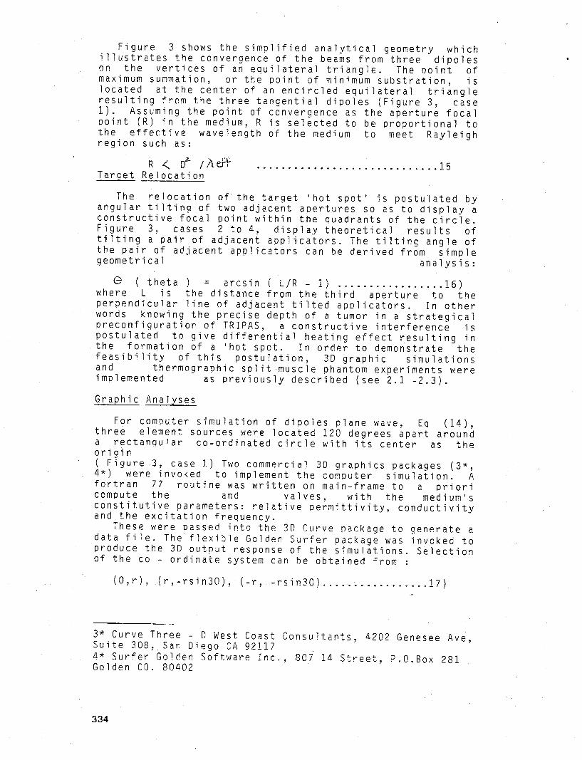
Figure 3 shows the simplified analytical geometry whichillustrates the convergence of the beams from three dipoleson the vertices of an equilateral triangle. The point ofmaximum summation, or the point of minimum substration, islocated at the center of an encircled equilateral triangleresulting from the three tangential dipoles (Figure 3, case1). Assuming the point of convergence as the aperture focalpoint (R) in the medium, R is selected to be proportional tothe effective wavelength of the medium to meet Rayleighregion such as:
Target Relocation
The relocation of the target ’hot spot’ is postulated byangular tilting of two adjacent apertures so as to display aconstructive focal point within the quadrants of the circle.Figure 3, cases 2 to 4, display theoretical results oftilting a pair of adjacent applicators. The tilting angle ofthe pair of adjacent applicators can be derived from simplegeometrical analysis:
~ ( theta ) = arcsin ( L/R - 1) ................. 16)where L is the distance from the third aperture to theperpendicular line of adjacent tilted applicators. In otherwords knowing the precise depth of a tumor in a strategicaloreconfiguration of TRIPAS, a constructive interference ispostulated to give differential heating effect resulting inthe formation of a ’hot spot. In order to demonstrate thefeasibility of this postulation, 3D graphic simulationsand thermographic split muscle phantom experiments wereimplemented as previously described (see 2.1 -2.3).
Graphic Analyses
For computer simulation of dipoles plane wave, Eq (14),three element sources were located 120 degrees apart arounda rectangular co-ordinated circle with its center as theorigin( Figure 3, case 1) Two commercial 3D graphics packages (3*,4*) were invoked to implement the computer simulation. Afortran 77 routine was written on main-frame to a prioricompute the and valves, with the medium’sconstitutive parameters: relative permittivity, conductivityand the excitation frequency.
These were passed into the 3D Curve package to generate adata file. The flexible Golden Surfer package was invoked toproduce the 3D output response of the simulations. Selectionof the co ordinate system can be obtained from :
(O,r), (r,-rsin30), (-r, -rsin30) ................. 17)
3* Curve Three D West Coast Consultants, a202 Genesee Ave,Suite 308~.San Diego CA 921174* Surfer Golden Software Inc., 80i I~ Street, P.O.Box 281Golden CO. 80402
334

Basic Dipoles Configuration
Case 1 Case
Case 3 Case 4
Figure 3. TRIPAS Analysis - Postulated Target RelocationArrows indicate dipoles strategically located aroundencircled equilateral triangle.Case l: Dipoles sum their plane - wave contributions at thecenter.Case 2: Pair dipoles rotated at their tangential mid -points by theta to enhance relocation of summationpoint (target) at the RHS of circular segment.Case 3. Pair dipoles rotated at their tangential mid - pointby theta to enhance relocation of summation point(target) at the Bottom circular segment.Case 4. Pair dipoles rotated at their tangential mid -points by theta to enhance relocation of summationpoint (target) at the LHS circular segment.
335

Three ~i~oles circularly located at the above rectanQularco- ordinates with center {0,0). The valve (r) is matchedto (R), the axial focal length, though (r) can bearbitrariTy selected. Each co ordinate goes into Eq. 4,respectively :
~y : Er.e (-~c (x+12.5)~2 + (y~5.3)^2)~1/2) ^.e (-/~ ((x+12.5)^2 + (v-_6.3)^2) 1/2)
.cos(6.283 (x+12;5)^2 + (y-6.3)^1/2~Y~) ......
~y : Er.e (-~ ((x-12.5)^2 -+ (~v~-6.3)~I/2)
.cos(6.283(ie (~.5((x-12 5)- 2 ~+ (y-6.3)^2)^1/2)x-1 )~’2 + iy-6.3) 2) 1/2~e(~) 18c)
for r = R = 12.5 Creating the plane wave superimposed on thetraveling surface wave ( see Figure 3a and Figure 5 )
ResultsSAR measurement
The results of the SAR measurements indicate that thetemperature increases obtained were greatest close to eachradiating aperture, and then lessened substantially, until azone of summation is reached, where they create a ’hotspot’ The SAR measurements at the 12.5 cm ’hot spot’closely approached those measured at the near field of theaperture (see Figure ~).
Phantom Temperature Determination
Thermal responses visualized on the liquid crysta! sheetsshowed three different zones of preferential heating :A ’hotspot’ was located close to #ach applicator. A second clearlydefined heat zone appeared at the center of the phantom, atthe point of beam interaction. Both of these zones are about6 cm in diameter. A third heat zone is circumferential aboutmidway between the peripheral and central hot spot ( seeFigure 2), about 3.~ cm wide ( one Quarter of the effectivewavelength of 13.4 cm at 300 MHz in the muscle Phantom).
Simulation
The results of the simulation of EQs. 18a - c aredisolayed 3-dimensionally in Figure 5. The inputs forcomputing the complex propagation constant and itscomponents (~,~) simulated in the muscle tissue excited at
336

SUMMARY RESULTS
11/19/86 PM
12.5 cm (TRIPAS) PI’LANTOM
60 Second Time
600 WATTS Power
ANTENNA #I
85
109
73
38
84
TENNA #2
" ~ 9cm2~8 = _ ~
ANTENNA #3
SAR TRIPAS 600 WATTS (I MINUTE)
Figure 4. TRIPAS - SAR Profiles
SAR (specific absorption ratio) measured inmuscle phantom, using 300 MHz atequally split among three equivalent(dimension,design) for 60 seconds. SAR’sof summation approximate those near theeo~licator aDeratures.
a triangular600 Wattsapplicators
in the areafront of the
337

300 MHz, were : permittivity value of 54 F/m andconductivity value of 1.07 S/m, with free space permeabilityvalue of !2.57x10 H/m and the permittivity of free space as8.854xi0 F/m. These parameters were apDropiately scaled asinput variables into the graphic package for the data file.The selection of effective wavelength (~eff) can becalculated theoretically, but in this case was extrapolatedfrom the muscle ohantom heating pattern studies. A typicalvalue of ~eff= 13.a cm was used ( see SAR measurements ).
bysurface expression ( seedisplays the 3D output surfletter marker A,B and C i, strategically located atconfiguration. The arrow
The dispersive effect of the plane wave was accomplishedthe addition of electromagnetic plane wave solution with
Eas.(14) and (15)). Figure 5ace plot of the simulation. Thendicate the origin of the diooles120 degree separation in circularmarker points to the central
summation ’ hot spot’. The main features highliahted bythese 3D plots are : 1) high intensity singularity in frontof each simulated aperture, 2) rapid decay in amplitudeintensity due to generation of destructive interference fromsubtractive surface waveforms, 3) at even greater depth asecond high intensity area due to additive interferencecausina a peaking standing wave, 4) followed by subtractiveinterference creating an intensity valley and 5) finallyproducing the theoretically predicted summation at thecentrally located ’ hot spot’ The high intensity peak atthe aPerture (source) is a common observation inexperimental and theoretical modellings (Bach Andersen 1984,Gee et al .1984, Kantor and Cetas 1977), that accounts fornear- field effects. The surface dispersive effect ispredominant at the viewing angle in this simulation. Theamplitude steering (modulation) of the target ’hot spot’ isimplemented by the inclusive term E Eqs. 18a-c. It should benoted that the above surface plot is in very good agreementwith experimental observations as described earlier,(comparing Figures 2 and 5). Note, this specifically appliedto case i of Figure 3 relating to the theoreticalpostulation.
Discussion
The present results make use of a mathematical model ofradiating dipoles to predict the coherent and noncoherentinterference of three converging electromagnetic wavesources interacting within biological media to produce arelocatable ’hot s~ot’ The muscle-~hantom experimentalresults in part verified this postulation.
Previous studies (Bach Andersen 1984,Turner and Kumar1982, Wait 1986),solved domain-integral equations forelectric field vector ~otential as a result of inducedmagnetic current elements derived from fundamental Maxwell’sclassic microscopic equations, provided versatility ofimplementing the medium heterogeneity. Turner and Kumar(1982,’84) used Huygen’s principle to simulate a horn-tyoeapolicator as an array of point-source dipole radiators, inorder to predict the heating patterns and ~erformance of the
338

Figure 5. TRIPAS - Simulatien
3D surface plot displaying pattern of split 300MHzmicrowave beams into muscle phantom.Note:l) the area of central converaence indicated byarrow(as postulated in Fig. 3 case I), ~) high intensitythermal field in front of each applicator (A,B, and C) and3) circular area of positive interference at approximate I/8wavelength depth between the applicator and the convergentcenter.
339

aperture. Such mathematical model was limited in its abilityto soatial!y predict the interaction of harmonically excitedplane waves in biological medium. Johnson et al. (1984,’85)and Sato (1986) analyzed circular compact arrays simulatingresonance conducting p~ates as magnetic current sources. Amathematical integration over the aperture surface yieldsfield distribution. This computational method is limited bythe convergence or divergence of the numerical technioueused for the integration.
Bach Andersen (1984] modelled an array of dipoles toexplicitly define radiative antenna gain for oower densityat a given ~oint relative to the total input Dower. Thisconcept was used to analyze radiative apertures and theirpenetration capability in biological tissue. This author(Bach Andersen 1984) further showed the theoreticalsynthesis of one- dimensional convergent beams meeting at afocal ooint to produce constructive interference. Hep~ctorially demonstrated that two waves traveling inoDoosite directions produce either an additive coherence orsubtractive noncoherence effect. The present investigationfollowed the same theoreticaI postulation.
For cylindrical geometry the larQe number of waves add toproduce power intensity convergence at the axis (Lin 1982).This central cylindrical ~ocusing is oenerally applied inregional heating of cylindrical tissue, (Samu!ski et al.,1987 and Turner 1984), but lacks the flexibility to relocatea localized ’hot spot
Nilsson et al. (1985) tilted two applicators at 45degrees. They reported a distinct heatin~ pattern when boththe radiative source had no phase relationship, whileconstructive and destructive interference were observed whenboth app!icators were excited in Phase coherently.
Gee et al. (1984), Bach Andersen (1984) and Ling et al(1984) Presented theoretical and experimental models of near~eld ~hased array focusing analyzed in 3D plane waveprofiles. The alternative use of an interactive Diane wavesmodel might ease the limitations inherent in the abovesimulation techniques.
Earlier, we ~e~orted (Bicher et al 1985) an experimentalparallel opposed s~stem that achieved therapeutictemperatures in the 42 to 43 degree Celsius range at 8 cmdepth in both muscle e~uivalent phantom and in pigs 20-30cm thicK. !n other papers (Bicher et al 1982, 84, ’86) wedefined the clinically usable penetration using one aircoo~ed applicator operated at 300 MHz to be 5 cm. UsinmPOPAS (two o~oosed applicators operated in phase), we wereable to heat theroeutically to a depth of 8 cm. By olacinmone aDolicator anteriorly and the other posteriorly,treatment of tumors at moderate depth, in thorax, abdomenand pelvis, have proved successful.
Our results of in vitro experiments and mathematicaIsimulation ( Figure 3, case i) clearly show effectiveheatinQ at a depth of 12.5 cm using 3 convergin~ microwave
340

beams from standard 300 MHz external applicators. Theflexibility of the system (TRIPAS) and the ability to changethe incident angle of the beams to relocate the ’ hot spot’within the target volume, make the system extremelypractical for the treatment of deep seated tumors, withoutthe need to heat an entire body region as is required withcurrent phased array systems which operate at lowerfreauencies. P~sitioning of the air gap applicators aroundthe patient is quick and easily reproducible. TheseaDolicators have poor coupling however, so there is someenergy loss. ~n the present system this is compensated bythe use of a high power generator operating at fixedfreouency (300 MHz), capable of 300 watts per applicator.Thus a 900 watts generator for TRIPAS wi!l be required forclinical use. Such a device has already been built and isoperational in our laboratory.
The good correlation between our mathematical predictionsand phantom studies validates the theoretical approach used.The ability of the TRIPAS system to predict the location ofthe ’hot spot’ within the treatment field makes computer~lannina o~ the applicators ~ositionino in the clinicalsituation feasible.
NomenclatureD = aD~licator aperture dimension (cm)Er = axial spatial electric field magnitude (v/cm)Ey : electric field complex vector (v/cm)f = frequency (MHz)
= magnetic field omplex vector (A/cm)= imaginary operator (Sq.root (-1))= numerical approximate integer for axial E -= distance from the aperture to target - tumor= axial aperture focal length (cm): graphical radius
x,y,z = rectangular coordinate system= 2’~f ; angu!art frenquency Irad)= attenuation factor (Np/m)= phase factor (rad/m)=conductivity of the medium (S/m)= relative dielectric constant
./~ = free space ~ermeabiliti (H/m)=complex ~ropagation constant (H.Np/m)
eff = effective wavelength (cm/ cycle)(theta) = tilting axial aperture angle (deg)= vector differential operator
~= laplace o~erator= variable incrememt
field(cm)
REFERENCES
1) Bach Andersen, J~review. Proceedings ofHyperthermia Oncology,(London, Philadelphia:128.
1984, Eletromagnetic heating - athe 4th International symposium on
Aarhus, Vol. 2, ed. J. OvergaardTaylor & Francis, 1984), pe. 113 -
341

2) Bach Andersen, J: 1984, Theoretical limitation onradiation into muscle tissue. International Journal ofHyperthermia, 1, a5 55.
3) Arcangeli, G., Lombardini, P.P., Lovisolo G. A.Marsiglia G. and Piattelli, M., 1984, Focusing of 915 ~Hzelectromagnetic power on deed human tissue: a mathematicalmodel study. IEEE Transactions Biomedical Engineering, BME31, 47 -5a.
~) Bicher, H. I., Sandh~, T. S., and Hetzel, F.Hyperthermia as a radiation adjuvant : Anfractionati.on regime. International Journal ofOncology, Biology. Physics. 5,!71.
W., 1979,effective
Radiation,
5) Bicher, H.I., Sandhu, T.S., and Hetzel, F.W., 1980,Hyperthermia and radiation ~n combination. International~Journal of Radiation, Oncology, Biology, Physics, 6, 867870.
6) Bicher, H. I., Hetzel, F. W., and Sandhu, T. D.S., 1982.Results of a ohase I/II clinical tria! of fractionatedhyperthermia in combination with low dose ionizingradiation. Advance Exoerimental Medical Biology, !57, 87 -97.
7) Bicher, H. I., 1984, The Set up of the state of artHyDerthermia clinic - therapeutic, "ethical, and mracticalconsiderations. Frontiers in Radiation Theraoy Oncology, 18,153 161.
8) Bicher, H. I., and Wo!fstein, R. S., 1984, MicrowavehyDerthermia as an adjuvant to radiation therapy. Summaryexperience of 208 mu~tifraction treatment cases.H.v~erthermia Oncology, vol. 1, ed. by J. Overmaard (London,Phi!adelDhia : Taylo~ & Francis, 1984),~. 363--366.
9) Bicher, H. I., Moore, D. W., and Wolfstein, R. S., 1985,Air cooled 300 MHz ADplicators used in a marallel opposedphased (POPAS). International Journal of Radiation,Oncology, Biology, Physics, 11,$I, 2!7.
!01 Bicher, H. I., and Wolfstein, R. S., 1986, Microwavehyperthermia as an adjunct to radiation therapy: Summaryexperience of 256 multifraction treatment cases.Interationa~ Journal of Radiation, Oncology, Biology,Phisics 12,1667 1671.
11) Bicher, H. I., and Wo~stein, R. S., 1986 Loca!hymerthermia for deep tumors experience with threetechnimues. Journal of Microwave Power, 21, 103.
12) Gee, W., ~ee, S., Bong, N. K., Cair, C. A., Mittra, R.,and Magin, R. L., 1984~Focused array hyperthermiaapnlicator: therory and ex.periment. IEEE Transactions.Biomedica!; Engineering, BME 31, 38-46.
342

13) Guy, A W., 19781, Electromagnetic fields and relativeheating petterns due to a rectangular aperture source indirect contact with bilayered biological tissue. IEEETransactions. Microwave Theory and Technique, MTT -19, 214 -223.
14) Guy, A. W., Lehmann, J.T., and stonebridge, J.B., 1974,Therapeutic application of electromagneticDower. Proceedings of the IEEE, 22,55 -75.
15) Guy, A.W., Lehmann, J.F., stonebridge, J.B., andSorensen, C.C., 1978, Development of a 915 MHz directcontact apDlicator for therpeutic heating of tissues, leeeTransactions. Microwave Therory and TechniQues, MTT 26,550 -556.
!6) Johnson, C.C., Durey C.H., and P!enk, H. P., 1977,Exnerimenwith 915 MHz hyperthermia treatment of malignanttumors. Journal of Bioengineering. 1, 511 - 530.
!7) Johnson,R.H., James, J. R., Hand, J.W , 1984, Hopewell,J. W, Dun!op, P.R.C, and Dickson, R.J., New low- profileapnlicators for local heating of tissues. IEEETransactions. Biomedical Engineering, BME - 31, 28 - 37.
18) Johnson, R. H., Andrasic, g., Smith, O. L., and James,J. R., 1984, Field penetration of arrays of compacta~plicators in localized hyperthermia. International Journalof Hyperthermia I, 29 -43.
19) Kantor, G., 1981, Evaluation and survey of microwave andradiofreQuency applicators. Journal of Microwave Power 16,135 - !50.
20) Kantor, G., and Cetas, T. C., 1977, A comparativeheating pattern study of direct - contact applicators inmicrowave diathermy. Radio Science, 12, 6S, 111 - 120.
21) Kritikos, H. N., Foster, K. R. and Schwan, H. P., 1981,Temperature profiles in spheres due to electromagneticheating. Journal of Microwave power, 16 (3&4), 327 - 344.
22) Lin,J.C.,Kantor G., and Ghods, A., 1982, A class of newmicrowave therapeutic applicators. Radio science~ 17 5S,]195 - 1235.
23) Ling, H., Lee, S.W., and Gee, W., 1984, FreQuencyoptimization of focused microwave hyperthermia applicators.Proceedings of the IEEE, 72, 224 -225.
24) Nilsson, P., Larsson,T., and Persson, B., 1985, Absorbedpower distribution from two tilted waveguide applicators.~nternational Journal of hyperthermia, i, 29 -43.
25) Samulski, T. \I.,Lohrbach, A., !987,
Kapp~ D. S.~ Fessenden, P.~ andHeating deed seated eccentrically
343

located tumors with an annular phased array system: Acomoarative clinical study usino two annular array operatingconfiauration. International Journal of Radiation, Oncology,Biology, Physics, 13, 83 94.
26) Sato, G., Shibata, C., Sekimukai, S., Wakabayashi, H.,and Mitsuka, K., 1986, Phase - controlled circular arrayheating eauioment for deep - seated tumors: Preliminaryexperiments. IEEE Transaction. Microwave Theory andTechniques ~TT 34, 520 524.
27) Turner, P. F., and Kumar, L., 1982, Comouter solutionfor applicator heating patterns. National Cancer InstituteMonograph, 61, 52! 523
28) Turner, P. F., 1984, Regiona! hyperthermia with anannular phased array. IEEE Tranaction. BiomedicalEngineering, BME 31, !06 - 1!9.
29) Wait, J. R., !986, Analysis of the radiation leakage fora Four - aperture phased - array applicator in hyperthermiatherapy. IEEE Transactions, Microwave Theory and TechniauesMtt 34 539 541.
344