Embed Size (px)
Citation preview
CAT. 0114-GB
Screw-on quick-release couplings
�
UNI EN ISO 9001Cert. n° 2905ISO/TS 16949

• Screw-on connection system.• Connection sleeve with flats
for screw-wrenching.• Screw-on system ensures
connection under pressure.• Great resistance to vibrations
and pressure peaks.• Rolled surfaces in sealing area
to ensure the lowest roughness.• Internal components purposely
designed to reduce turbolencesand consequent pressure drop.
• Hardened valve bodies to standcrashes.
• Contenitive washer with specialseal to reduce the risk of extrusion.
• Reinforced guidevalve withmechanical backstop to preventpartial enclosures of valves due to flow inversion and peaks.
• NBR seals.• PTFE backup ring.• Metal shoulder to protect the
O-ring seal on female coupling.• Wide range of threads
and connectors.• Ease of maintenance.• Accessories and spare parts kit
available with detailed assemblinginstructions.
• Similar products:CVV series (catalogue n° 0116), 3FFV series (catalogue n° 0113).
VV series• Double function sleeve
(Faster patented) for screw and balls bearing latching.
• Interchangeable with NV series male couplings (catalogue n° 0115).
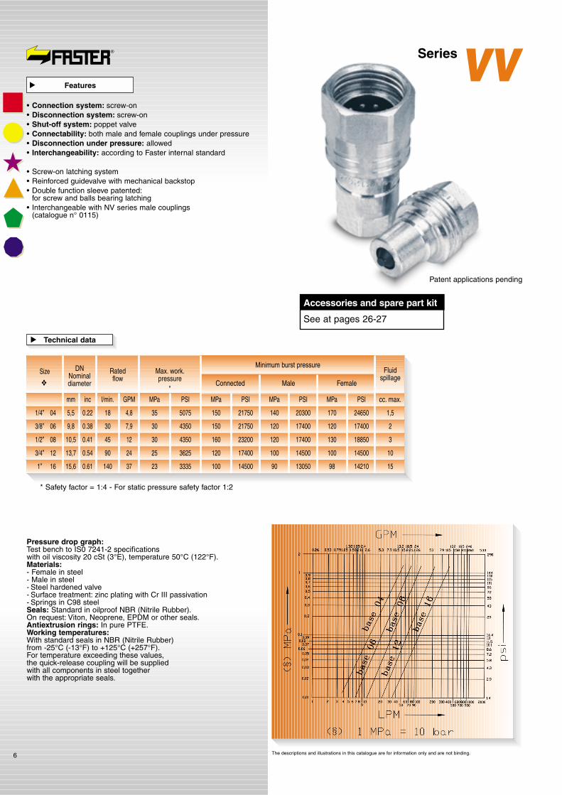
VVS series• Purposely dimensioned to stand
very high pressures and peaks.• Interchangeable with VV
series couplings.• Also available in Brass
and Stainless Steel.
FB series• Flat-face shut-off valves:
no spillage.• Wing-shaped sleeve to help
connection by hand and with hexagon for screw-wrenching.
• Interchangeable for the US market.• Also available in Steel.
CVE series• Wing-shaped sleeve to help
connection by hand and with hexagon for screw-wrenching.
• Suitable for panel mounting.• Interchangeable for the
European market.
PVVM series• Purposely dimensioned to stand
very high static pressures.• Poppet shut-off valve.• Interchangeable for US and
European market.• Also available in Stainless Steel.
Features Applications
� �
• Great resistance to vibrations,pressure peaks, water-hammers.
• Connection under full working pressure.
• Special seals to stand connection under pressure.
VV series• Interchangeable with NV
series male couplings (catalogue n° 0115).
VVS series• Purposely dimensioned
to stand very high pressures and peaks.
FB series• Flat-face shut-off valves:
no spillage.• Interchangeable for the
US market.
CVE series• Interchangeable for the
European market.
PVVM series• Purposely dimensioned
to stand very high static pressures.
• Interchangeable for US and European market.
Benefits
�
SCREW-ON QUICK-RELEASE COUPLINGS
�
2
The screw-on type coupling ensures a positive and firm connection between male and female part.This characteristics is usually found in high peak pressure spikeswith hose bendings and vibrations.The screw-on couplings are particularly suitable for all applications with pressure and flow peaks and when it is often necessary to connect and disconnect with residual pressure inside.

• If the connection phase is carriedout at residual pressure, the required force could be higher than the human one, therefore it is necessary to reducethe internal pressure of the coupling.
• Dirt on male or female part duringcoupling operations can causeseals damage.
• In order to ensure long service life of seals it is recommended to carefully clean mating parts,easily and quickly done thanks to coupling design.
• In case of seals damage it isnecessary to replace them byFASTER® original spare parts.
• The 3FFV series quick-releasecouplings can be connected under full working pressure.The necessary force to connect is proportional to the internal pressure and in case it is veryhigh is possible to use standardtools thanks to the special shape of the sleeve
• When disconnected, use suitableFASTER® covers to protect couplings from dirt.
• The recommendations stated in this catalogue do not consider all risk factors in every possible application of FASTER®
couplings.• The final choice of the product
is under customer’s responsibilitywho has to make the selectionaccording to FASTERsuggestions.
• The customer has to make surethat all requirements of chosenparts are respected, efficiency is maintened and the end user is informed about use and maintenance operations.
• FASTER and its Distributors are not responsible for damagesto persons and machines causedby an improper use and an incorrect maintenance of products.
• Increase of products’ technicaland functional features is FASTER’s policy.For that reason all data in thiscatalogue are not binding.FASTER is entitled to modify the specifications without prior notice.
• See available item codes in theordering chart.
• As a further help in defining and selecting the most suitableproduct for the specific application please ask and fill-inwith as much information as possible the Product DefinitionForm (mod. A003) sending it back to Faster CustomerService.
Attention! Responsabilities
• Improper use and incorrectmaintenance of products withhigh internal working pressurescould cause malfunctioning anddamage to persons and machines.Therefore it is necessary to carefully conform to the simpleinstructions contained in this catalogue.For any further information pleasecontact FASTER® TechnicalDepartment.
• Before using a new quick-releasecoupling, please carefully check all data reported in our catalogues.
• Make sure that the coupling is suitable for pressure and flowcharacteristics requested by the applications.
• Lubricate the seals and perform a connect and disconnect operationin order to check the perfect functioning of the coupling.
• Verify that threads fit and that their sealing is correct.
• If necessary replace damagedcomponents with FASTER®
original spare parts.• Before any connection
and disconnection carefullyclean both male and female partsto prevent dirt inclusions into the circuit and consequent sealsdamage.When couplings are disconnected,please protect them with originalFASTER® plugs.
Recommendations
� �
How to order
�
�
• All FASTER® quick-release couplings are designed and produced in conformity with theregulations of Quality ManagingSystem according to UNI ENISO 9001 and UNI ISO/TS 16949.
• They bear the FASTER® logo to guarantee their origin and reliability.
• FASTER® quick-release couplingsare distributed worldwide through a network of highly qualified distributors.
• If a FASTER® quick-release coupling is connected to an equivalent competitor’s type please check the functionality,the sealing and the resistance to working pressure beforeusing the coupling.FASTER cannot assure theperformance, quality and connecting tolerances of competitor’s types.
• Malfunctioning or leakages due tothe above mentioned cases couldcause serious damages to persons and machines.
Guarantee
�
3
UNI EN ISO 9001Cert. n° 2905ISO/TS 16949
• Zinc plating with Cr III passivation on the whole range
N O V E L T I E S I N T H I S C A T A L O G U E
�

Screw-on couplings
4
SeriesVV

�������
������
������������
���
�����������
�����
����
�������
������
�����������
��
Hexagonshapedsleeve
Metal shoulderwith PTFE
backup ringagainst
extrusionproblems
Wide contactarea when
the couplingis connected
Valves withspecial profiledseals to prevent
extrusion
Balls bearingto allow
connectionwith NV series
male parts
Reinforcedinternal
components
FASTER® logoguaranteesreliability
and the originof the coupling
Screw-onsystem
to connectunder
pressure
Series NV38...MPatented
In the picture
The descriptions and illustrations in this catalogue are for information only and are not binding.
Series
VV38...F
In the picture
Patent applications pending
��
���
� � � � � �
Series
VV38...M
In the picture
�����
5
1) It can be easily connected with both VV series male part and with standard NV series male part.2) Connection can be done with one or both parts under pressure by using a spanner.3) A wide contact area between the two parts ensures high resistance to cyclic pressure.4) High seal resistance even to hose bendings.5) Extremely compact if compared to the performances.6) VV series couplings can be designed in anodized aluminium with latching balls and springs made of stainless steel.7) VV series can be designed with metal to metal sealing in order to stand very high flowrates.
T H E N E W R E V O L U T I O N A R Y W A Y O F T H E Q U I C K - R E L E A S E C O U P L I N G S
�
The descriptions and illustrations in this catalogue are for information only and are not binding.
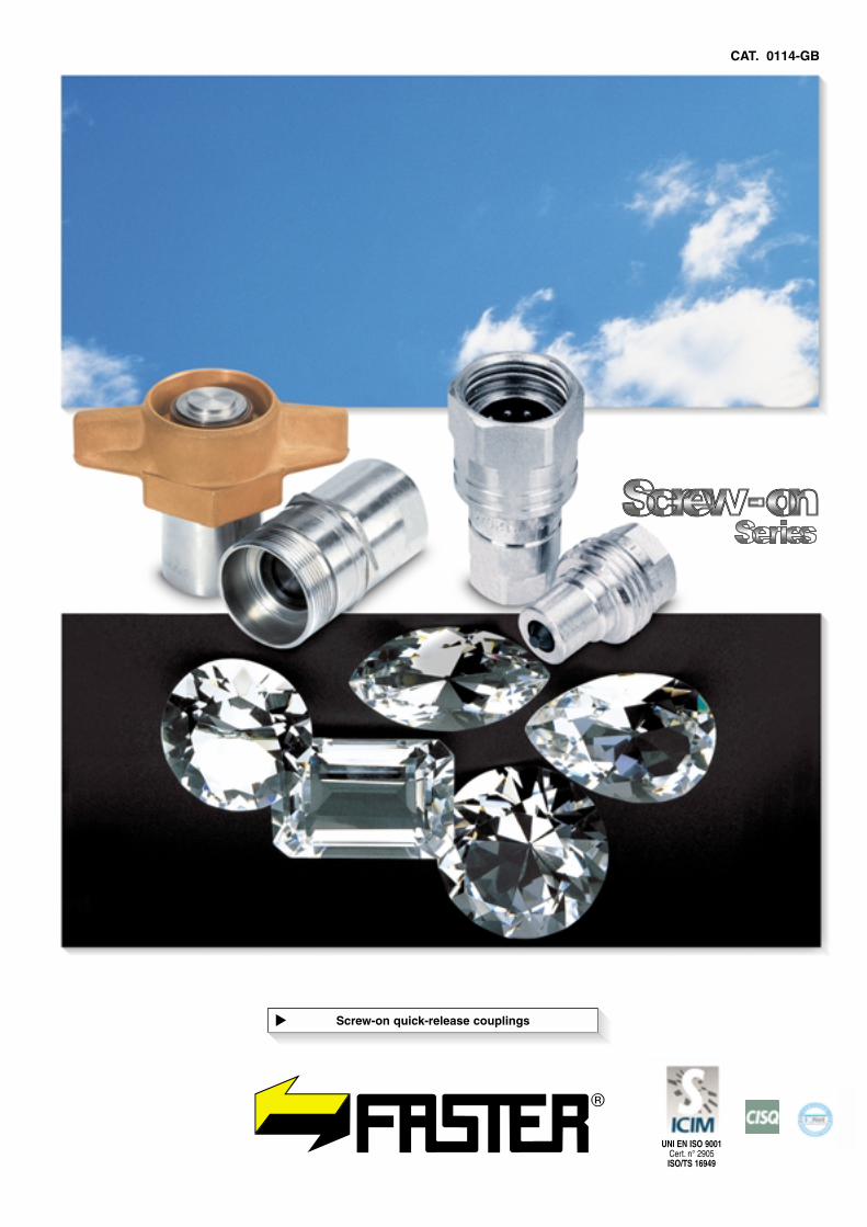
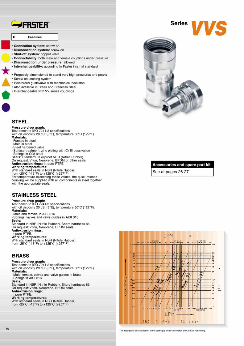
Pressure drop graph:Test bench to IS0 7241-2 specifìcations with oil viscosity 20 cSt (3°E), temperature 50°C (122°F).Materials:- Female in steel- Male in steel- Steel hardened valve- Surface treatment: zinc plating with Cr III passivation- Springs in C98 steel Seals: Standard in oilproof NBR (Nitrile Rubber).On request: Viton, Neoprene, EPDM or other seals.Antiextrusion rings: In pure PTFE.Working temperatures:With standard seals in NBR (Nitrile Rubber) from -25°C (-13°F) to +125°C (+257°F).For temperature exceeding these values, the quick-release coupling will be supplied with all components in steel together with the appropriate seals.
6
Series
Patent applications pending
VV
Accessories and spare part kit
See at pages 26-27
• Connection system: screw-on• Disconnection system: screw-on• Shut-off system: poppet valve• Connectability: both male and female couplings under pressure• Disconnection under pressure: allowed• Interchangeability: according to Faster internal standard
• Screw-on latching system• Reinforced guidevalve with mechanical backstop• Double function sleeve patented:
for screw and balls bearing latching• Interchangeable with NV series male couplings
(catalogue n° 0115)
Features
�
* Safety factor = 1:4 - For static pressure safety factor 1:2
Size
mm l/min. MPa MPa MPaPSI PSI PSIGPM
Ratedflow
Max. work.pressure
Connected Male Female
Fluidspillage
cc. max.
Minimum burst pressure
1/4” 04
DNNominaldiameter
5,5 0.22 35 5075 150 21750 140 170 24650 1,52030018 4,8
3/8” 06 9,8 0.38 30 4350 150 21750 120 120 17400 21740030 7,9
1/2” 08
3/4” 12
10,5
13,7
0.41
0.54
30
25
4350
3625
160
120
23200
17400
120
100
130
100
18850
14500
3
10
17400
14500
45
90
12
24
inc MPa PSI
Technical data
�
*❖
1” 16 15,6 0.61 23 3335 100 14500 90 98 14210 1513050140 37

Series VV
Female Male A Male B Ø A
04
B C C1 L L1 CH CHDSleevemm inc. mm inc. mm inc. mm inc. mm inc. mm inc. mm inc.Standards❖
❖ Size GAS = BSP *On request
The descriptions and illustrations in this catalogue are for information only and are not binding.
VV14GAS F VV14GAS M NV14GAS M 1/4” BSP DIN 3852-2-XVV14NPT F VV14NPT M NV14NPT M 1/4” NPTF ANSI B1.20.3 50 1.97 33 1.3 33 1.3 66 2.6 66 2.6 19 0.75 27 1.06VV14-14SAE F VV14-14SAE M 7/16” UNF SAE J1926-1
1” - 12 UNF
VV38GAS F VV38GAS M NV38GAS M 3/8” BSP DIN 3852-2-XVV38NPT F VV38NPT M NV38NPT M 3/8” NPTF ANSI B1.20.3 59.5 2.34 39 1.53 40.5 1.59 78 3.07 79.5 3.13 24 0.94 34 1.34VV38-38SAE F VV38-38SAE M 9/16” UNF SAE J1926-1
11/4” - 8 UN
VV12GAS F VV12GAS M NV12GAS M 1/2” BSP DIN 3852-2-XVV12NPT F VV12NPT M NV12NPT M 1/2” NPTF ANSI B1.20.3 66 2.6 44 1.73 49 1.93 88 3.46 93 3.66 27 1.06 38 1.5VV12-12SAE F VV12-12SAE M NV34UNF M 3/4” UNF SAE J1926-1
13/8” - 8 UN
VV34GAS F VV34GAS M NV34GAS M 3/4” BSP DIN 3852-2-XVV34NPT F VV34NPT M NV34NPT M 3/4” NPTF ANSI B1.20.3 84 3.3 55 2.16 62 2.44 110 4.33 117 4.6 34 1.34 50 1.97VV34-34SAE F VV34-34SAE M 1-1/16” UN SAE J1926-1
13/4” - 6 UN
VV1GAS F VV1GAS M NV1GAS M 1” BSP DIN 3852-2-XVV1NPT F VV1NPT M NV1NPT M 1” NPTF ANSI B1.20.3 99.5 3.92 66 2.6 70 2.75 132 5.19 136 5.35 41 1.6 55 2.16VV1-1SAE F VV1-1SAE M 1-5/16” UN SAE J1926-1
M52X4
06
08
12
16
* *
* *
* *
* *
VV Male NV MaleFemale
7
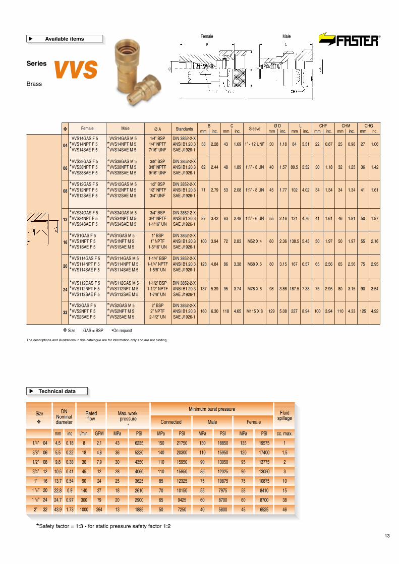
Available items
�

Screw-on couplingsfor very high pressure
8
SeriesVVS
��������
�����
���
�������������
�������������������
������
��������
���
���
���������
�����
�
� � � � � �
� � � � � � � � � � � � � � � � � � � � � � � � � � �
Reinforcedinternal
components
A partof the sleeveis hexagon
shaped
Screw-onconnection
Easymaintenance
Valveswith special
profiled sealsto preventextrusion
Metalshoulderwith PTFE
backup ring
Widecontact area
when thecoupling isconnected
9
Series VVSPatented
In the picture
� � � �
� � � �
� � � � � � �
����
Ergonomicsleeve
����������
The descriptions and illustrations in this catalogue are for information only and are not binding.
1) Purposely dimensioned for heavy duty applications.2) Extremely resistant to cyclic pressures.3) The screw-on connection allows connection with one or both parts under pressure by using a spanner.4) High seal resistance even to hose bendings.5) Interchangeable with VV series couplings.
T H E N E W R E V O L U T I O N A R Y W A Y O F T H E Q U I C K - R E L E A S E C O U P L I N G S
�
Pressure drop graph:Test bench to ISO 7241-2 specifications with oil viscosity 20 cSt (3°E), temperature 50°C (122°F).Materials:- Female in steel- Male in steel- Steel hardened valve- Surface treatment: zinc plating with Cr III passivation- Springs in C98 steelSeals: Standard in oilproof NBR (Nitrile Rubber).On request: Viton, Neoprene, EPDM or other seals.Antiextrusion rings: In pure PTFE.Working temperatures:With standard seals in NBR (Nitrile Rubber) from -25°C (-13°F) to +125°C (+257°F).For temperature exceeding these values, the quick-release coupling will be supplied with all components in steel together with the appropriate seals.
Pressure drop graph:Test bench to ISO 7241-2 specifications with oil viscosity 20 cSt (3°E), temperature 50°C (122°F).Materials:- Male and female in AISI 316- Springs, valves and valve guides in AISI 316Seals:Standard in NBR (Nitrile Rubber), Shore hardness 85.On request: Viton, Neoprene, EPDM seals.Antiextrusion rings:In pure PTFE.Working temperatures:With standard seals in NBR (Nitrile Rubber) from -25°C (-13°F) to +125°C (+257°F).
10
STEEL
STAINLESS STEEL
Pressure drop graph:Test bench to ISO 7241-2 specifications with oil viscosity 20 cSt (3°E), temperature 50°C (122°F).Materials:- Male, female, valves and valve guides in brass- Springs in AISI 316Seals:Standard in NBR (Nitrile Rubber), Shore hardness 85.On request: Viton, Neoprene, EPDM seals.Antiextrusion rings:In pure PTFE.Working temperatures:With standard seals in NBR (Nitrile Rubber) from -25°C (-13°F) to +125°C (+257°F).
BRASS
The descriptions and illustrations in this catalogue are for information only and are not binding.
SeriesVVS
Accessories and spare part kit
See at pages 26-27
• Connection system: screw-on• Disconnection system: screw-on• Shut-off system: poppet valve• Connectability: both male and female couplings under pressure• Disconnection under pressure: allowed• Interchangeability: according to Faster internal standard
• Purposely dimensioned to stand very high pressures and peaks• Screw-on latching system• Reinforced guidevalve with mechanical backstop• Also available in Brass and Stainless Steel• Interchangeable with VV series couplings
Features
�

Series VVS
MaleFemale
Female
VVS14GAS F VVS14GAS M 1/4” BSP DIN 3852-2-XVVS14NPT F VVS14NPT M 1/4” NPTF ANSI B1.20.3 58 2.28 43 1.69 1” - 12 UNF 30 1.18 84 3.31 22 0.87 25 0.98 27 1.06VVS14SAE F VVS14SAE M 7/16” UNF SAE J1926-1
VVS38GAS F VVS38GAS M 3/8” BSP DIN 3852-2-XVVS38NPT F VVS38NPT M 3/8” NPTF ANSI B1.20.3 62 2.44 48 1.89 11/4” - 8 UN 40 1.57 89.5 3.52 30 1.18 32 1.25 36 1.42VVS38SAE F VVS38SAE M 9/16” UNF SAE J1926-1
VVS12GAS F VVS12GAS M 1/2” BSP DIN 3852-2-XVVS12NPT F VVS12NPT M 1/2” NPTF ANSI B1.20.3 71 2.79 53 2.08 13/8” - 8 UN 45 1.77 102 4.02 34 1.34 34 1.34 41 1.61VVS12SAE F VVS12SAE M 3/4” UNF SAE J1926-1
VVS34GAS F VVS34GAS M 3/4” BSP DIN 3852-2-XVVS34NPT F VVS34NPT M 3/4” NPTF ANSI B1.20.3 87 3.42 63 2.48 13/4” - 6 UN 55 2.16 121 4.76 41 1.61 46 1.81 50 1.97VVS34SAE F VVS34SAE M 1-1/16” UN SAE J1926-1
VVS1GAS F VVS1GAS M 1” BSP DIN 3852-2-XVVS1NPT F VVS1NPT M 1” NPTF ANSI B1.20.3 100 3.94 72 2.83 M52 X 4 60 2.36 138.5 5.45 50 1.97 50 1.97 55 2.16VVS1SAE F VVS1SAE M 1-5/16” UN SAE J1926-1
VVS114GAS F VVS114GAS M 1-1/4” BSP DIN 3852-2-XVVS114NPT F VVS114NPT M 1-1/4” NPTF ANSI B1.20.3 123 4.84 86 3.38 M68 X 6 80 3.15 167 6.57 65 2.56 65 2.56 75 2.95VVS114SAE F VVS114SAE M 1-5/8” UN SAE J1926-1
VVS112GAS F VVS112GAS M 1-1/2” BSP DIN 3852-2-XVVS112NPT F VVS112NPT M 1-1/2” NPTF ANSI B1.20.3 137 5.39 95 3.74 M78 X 6 98 3.86 187.5 7.38 75 2.95 80 3.15 90 3.54VVS112SAE F VVS112SAE M 1-7/8” UN SAE J1926-1
VVS2GAS F VVS2GAS M 2” BSP DIN 3852-2-XVVS2NPT F VVS2NPT M 2” NPTF ANSI B1.20.3 160 6.30 118 4.65 M115 X 8 129 5.08 227 8.94 100 3.94 110 4.33 125 4.92VVS2SAE F VVS2SAE M 2-1/2” UN SAE J1926-1
Male Ø A
04
06
08
12
16
20
24
32
* *
* *
* *
* *
* *
* *
* *
* *
Bmm inc.
CSleevemm inc.
Ø Dmm inc.
Lmm inc.
CHFmm inc.
CHMmm inc.
CHGmm inc.Standards❖
❖ Size GAS = BSP *On request
The descriptions and illustrations in this catalogue are for information only and are not binding.
Steel
11
Available items
�
*Safety factor = 1:3 - for static pressure safety factor 1:2
Size
mm l/min. MPa MPa MPaPSI PSI PSIGPM
Ratedflow
Max. work.pressure
Connected Male Female
Fluidspillage
cc. max.
Minimum burst pressure
1/4” 04
DNNominaldiameter
4,5 0.18 80 11600 250 36250 240 240 34800 1348008 2,1
3/8” 06 5,5 0.22 76 11020 230 33350 290 250 36250 1,54205018 4,8
1/2” 08
3/4” 12
1” 16
9,8
10,5
13,7
0.38
0.41
0.54
73
70
53
10585
10150
7685
220
214
194
31900
31030
28130
238
212
160
220
230
224
31900
33350
32480
2
3
10
34510
30740
23200
30
45
90
7,9
12
24
1 1/4” 20 22,8 0.9 60 8700 200 29000 180 180 26100 1526100140 37
1 1/2” 24 24,7 0.97 40 5800 150 21750 120 150 21750 3817400300 79
inc MPa PSI
Technical data
�
*❖
2” 32 43,9 1.73 35 5075 105 15225 130 130 18850 46188501000 264

12
Series VVSStainlesssteel
MaleFemale
Female
VVS14GAS F 2 VVS14GAS M 2 1/4” BSP DIN 3852-2-XVVS14NPT F 2 VVS14NPT M 2 1/4” NPTF ANSI B1.20.3 58 2.28 43 1.69 1” - 12 UNF 30 1.18 84 3.31 22 0.87 25 0.98 27 1.06VVS14SAE F 2 VVS14SAE M 2 7/16” UNF SAE J1926-1
VVS38GAS F 2 VVS38GAS M 2 3/8” BSP DIN 3852-2-XVVS38NPT F 2 VVS38NPT M 2 3/8” NPTF ANSI B1.20.3 62 2.44 48 1.89 11/4” - 8 UN 40 1.57 89.5 3.52 30 1.18 32 1.25 36 1.42VVS38SAE F 2 VVS38SAE M 2 9/16” UNF SAE J1926-1
VVS12GAS F 2 VVS12GAS M 2 1/2” BSP DIN 3852-2-XVVS12NPT F 2 VVS12NPT M 2 1/2” NPTF ANSI B1.20.3 71 2.79 53 2.08 13/8” - 8 UN 45 1.77 102 4.02 34 1.34 34 1.34 41 1.61VVS12SAE F 2 VVS12SAE M 2 3/4” UNF SAE J1926-1
VVS34GAS F 2 VVS34GAS M 2 3/4” BSP DIN 3852-2-XVVS34NPT F 2 VVS34NPT M 2 3/4” NPTF ANSI B1.20.3 87 3.42 63 2.48 13/4” - 6 UN 55 2.16 121 4.76 41 1.61 46 1.81 50 1.97VVS34SAE F 2 VVS34SAE M 2 1-1/16” UN SAE J1926-1
VVS1GAS F 2 VVS1GAS M 2 1” BSP DIN 3852-2-XVVS1NPT F 2 VVS1NPT M 2 1” NPTF ANSI B1.20.3 100 3.94 72 2.83 M52 X 4 60 2.36 138.5 5.45 50 1.97 50 1.97 55 2.16VVS1SAE F 2 VVS1SAE M 2 1-5/16” UN SAE J1926-1
VVS114GAS F 2 VVS114GAS M 2 1-1/4” BSP DIN 3852-2-XVVS114NPT F 2 VVS114NPT M 2 1-1/4” NPTF ANSI B1.20.3 123 4.84 86 3.38 M68 X 6 80 3.15 167 6.57 65 2.56 65 2.56 75 2.95VVS114SAE F 2 VVS114SAE M 2 1-5/8” UN SAE J1926-1
VVS112GAS F 2 VVS112GAS M 2 1-1/2” BSP DIN 3852-2-XVVS112NPT F 2 VVS112NPT M 2 1-1/2” NPTF ANSI B1.20.3 137 5.39 95 3.74 M78 X 6 98 3.86 187.5 7.38 75 2.95 80 3.15 90 3.54VVS112SAE F 2 VVS112SAE M 2 1-7/8” UN SAE J1926-1
VVS2GAS F 2 VVS2GAS M 2 2” BSP DIN 3852-2-XVVS2NPT F 2 VVS2NPT M 2 2” NPTF ANSI B1.20.3 160 6.30 118 4.65 M115 X 8 129 5.08 227 8.94 100 3.94 110 4.33 125 4.92VVS2SAE F 2 VVS2SAE M 2 2-1/2” UN SAE J1926-1
Male Ø A
04
06
08
12
16
20
24
32
* *
* *
* *
* *
* *
* *
* *
* *
Bmm inc.
CSleevemm inc.
Ø Dmm inc.
Lmm inc.
CHFmm inc.
CHMmm inc.
CHGmm inc.Standards❖
❖ Size GAS = BSP *On request
The descriptions and illustrations in this catalogue are for information only and are not binding.
Available items
�
*Safety factor = 1:3 - for static pressure safety factor 1:2
Size
mm l/min. MPa MPa MPaPSI PSI PSIGPM
Ratedflow
Max. work.pressure
Connected Male Female
Fluidspillage
cc. max.
Minimum burst pressure
1/4” 04
DNNominaldiameter
4,5 0.18 60 8700 280 40600 180 280 40600 1261008 2,1
3/8” 06 5,5 0.22 65 9425 250 36250 195 200 29000 1,52827518 4,8
1/2” 08
3/4” 12
1” 16
9,8
10,5
13,7
0.38
0.41
0.54
60
50
46
8700
7250
6670
245
190
160
35525
27550
23200
180
150
150
195
160
140
28275
23200
20300
2
3
10
26100
21750
21750
30
45
90
7,9
12
24
1 1/4” 20 22,8 0.9 38 5510 150 21750 115 120 17400 1516675140 37
1 1/2” 24 24,7 0.97 36 5220 155 22475 110 140 20300 3815950300 79
inc MPa PSI
Technical data
�
*❖
2” 32 43,9 1.73 21 3045 85 12325 65 75 10875 4694251000 264
Series VVSBrass
MaleFemale
13
Female
VVS14GAS F 5 VVS14GAS M 5 1/4” BSP DIN 3852-2-XVVS14NPT F 5 VVS14NPT M 5 1/4” NPTF ANSI B1.20.3 58 2.28 43 1.69 1” - 12 UNF 30 1.18 84 3.31 22 0.87 25 0.98 27 1.06VVS14SAE F 5 VVS14SAE M 5 7/16” UNF SAE J1926-1
VVS38GAS F 5 VVS38GAS M 5 3/8” BSP DIN 3852-2-XVVS38NPT F 5 VVS38NPT M 5 3/8” NPTF ANSI B1.20.3 62 2.44 48 1.89 11/4” - 8 UN 40 1.57 89.5 3.52 30 1.18 32 1.25 36 1.42VVS38SAE F 5 VVS38SAE M 5 9/16” UNF SAE J1926-1
VVS12GAS F 5 VVS12GAS M 5 1/2” BSP DIN 3852-2-XVVS12NPT F 5 VVS12NPT M 5 1/2” NPTF ANSI B1.20.3 71 2.79 53 2.08 13/8” - 8 UN 45 1.77 102 4.02 34 1.34 34 1.34 41 1.61VVS12SAE F 5 VVS12SAE M 5 3/4” UNF SAE J1926-1
VVS34GAS F 5 VVS34GAS M 5 3/4” BSP DIN 3852-2-XVVS34NPT F 5 VVS34NPT M 5 3/4” NPTF ANSI B1.20.3 87 3.42 63 2.48 13/4” - 6 UN 55 2.16 121 4.76 41 1.61 46 1.81 50 1.97VVS34SAE F 5 VVS34SAE M 5 1-1/16” UN SAE J1926-1
VVS1GAS F 5 VVS1GAS M 5 1” BSP DIN 3852-2-XVVS1NPT F 5 VVS1NPT M 5 1” NPTF ANSI B1.20.3 100 3.94 72 2.83 M52 X 4 60 2.36 138.5 5.45 50 1.97 50 1.97 55 2.16VVS1SAE F 5 VVS1SAE M 5 1-5/16” UN SAE J1926-1
VVS114GAS F 5 VVS114GAS M 5 1-1/4” BSP DIN 3852-2-XVVS114NPT F 5 VVS114NPT M 5 1-1/4” NPTF ANSI B1.20.3 123 4.84 86 3.38 M68 X 6 80 3.15 167 6.57 65 2.56 65 2.56 75 2.95VVS114SAE F 5 VVS114SAE M 5 1-5/8” UN SAE J1926-1
VVS112GAS F 5 VVS112GAS M 5 1-1/2” BSP DIN 3852-2-XVVS112NPT F 5 VVS112NPT M 5 1-1/2” NPTF ANSI B1.20.3 137 5.39 95 3.74 M78 X 6 98 3.86 187.5 7.38 75 2.95 80 3.15 90 3.54VVS112SAE F 5 VVS112SAE M 5 1-7/8” UN SAE J1926-1
VVS2GAS F 5 VVS2GAS M 5 2” BSP DIN 3852-2-XVVS2NPT F 5 VVS2NPT M 5 2” NPTF ANSI B1.20.3 160 6.30 118 4.65 M115 X 8 129 5.08 227 8.94 100 3.94 110 4.33 125 4.92VVS2SAE F 5 VVS2SAE M 5 2-1/2” UN SAE J1926-1
Male Ø A
04
06
08
12
16
20
24
32
* ** *
* ** ** *
* ** ** *
* ** ** *
* ** ** *
* ** ** *
* ** ** *
* ** ** *
Bmm inc.
CSleevemm inc.
Ø Dmm inc.
Lmm inc.
CHFmm inc.
CHMmm inc.
CHGmm inc.Standards❖
❖ Size GAS = BSP *On request
The descriptions and illustrations in this catalogue are for information only and are not binding.
Available items
�
*Safety factor = 1:3 - for static pressure safety factor 1:2
Size
mm l/min. MPa MPa MPaPSI PSI PSIGPM
Ratedflow
Max. work.pressure
Connected Male Female
Fluidspillage
cc. max.
Minimum burst pressure
1/4” 04
DNNominaldiameter
4,5 0.18 43 6235 150 21750 130 135 19575 1188508 2,1
3/8” 06 5,5 0.22 36 5220 140 20300 110 120 17400 1,51595018 4,8
1/2” 08
3/4” 12
1” 16
9,8
10,5
13,7
0.38
0.41
0.54
30
28
25
4350
4060
3625
110
110
85
15950
15950
12325
90
85
75
95
90
75
13775
13050
10875
2
3
10
13050
12325
10875
30
45
90
7,9
12
24
1 1/4” 20 22,8 0.9 18 2610 70 10150 55 58 8410 157975140 37
1 1/2” 24 24,7 0.97 20 2900 65 9425 60 60 8700 388700300 79
inc MPa PSI
Technical data
�
*❖
2” 32 43,9 1.73 13 1885 50 7250 40 45 6525 4658001000 264

14
SeriesFBScrew-on couplings with
wing-shaped sleeve for US market

���
�����
�������
�������
����������
��������
Deviceto indicate
whenconnection
is fullyachieved
Wing-shapedsleeve to help
connectionby hand
Flat valves:no spillage
Possibilityof panel
mounting
Reinforcedinternal
componentsHexagonfor wrenching
15
Series FBIn the picture
��
������
����
������� �
� � � �
The descriptions and illustrations in this catalogue are for information only and are not binding.
1) Flat-face valves to eliminate oil spillage during connection and disconnection.2) Wing-shaped sleeve to help manual connection.3) A part of the sleeve is hexagon shaped in order to connect or disconnect under pressure by using a spanner.4) It is possible to fit the male coupling by bulk head mounting to make the connection easier.5) A device indicates when connection is completely achieved in order to ensure maximum flow rate.
T H E N E W R E V O L U T I O N A R Y W A Y O F T H E Q U I C K - R E L E A S E C O U P L I N G S
�
Pressure drop graph:Test bench to ISO 7241-2 specifications with oil viscosity 20 cSt (3°E), temperature 50°C (122°F).Materials:Steel version:- Female and male part in steel zinced with Cr III passivation- Sleeve in brass- Springs C98Brass version:- Sleeve and male part in brass- Steel valves- Springs C98Antiextrusion rings:In pure PTFE.Seals:Standard in oilproof NBR (Nitrile Rubber).On request: Viton, Neoprene, EPDM or other seals.Working temperatures:With standard seals in NBR (Nitrile Rubber) from -25°C (-13°F) to +125°C (+257°F).For temperature exceeding these values, the quick-release coupling will be supplied with the appropriate seals.
16
SeriesFB
Patented
The descriptions and illustrations in this catalogue are for information only and are not binding.
• Connection system: screw-on• Disconnection system: screw-on• Shut-off system: flat valve• Connectability: both male and female couplings under pressure• Disconnection under pressure: allowed• Interchangeability: US market
• Screw-on latching system• Wing-shaped sleeve to help connection by hand• Hexagon for screw-wrenching• A device indicates when connection is fully achieved• Available in Brass• Steel version available on request• Interchangeable for US market
Features
�
Accessories and spare part kit
See at pages 26-27

Series FBSteel
Series FBBrass
Female
FB12/34NPT F FB12/34NPT M 3/4” NPTF ANSI B1.20.3 81 3.19 82 3.23 90 3.54 139 5.47 46 1.81 41 1.61 30 1.18 34 1.34
FB16/1NPT F FB16/1NPT M 1” NPTF ANSI B1.20.3 91 3.58 89 3.50 100 3.94 149 5.87 55 2.16 48 1.90 36 1.42 40 1.57
FB20/114NPT F FB20/114NPT M 1-1/4” NPTF ANSI B1.20.3 95 3.74 97 3.82 127 5 157 6.18 65 2.56 54 2.12 45 1.77 48 1.89
FB24/112NPT F FB24/112NPT M 1-1/2” NPTF ANSI B1.20.3 110 4.33 110 4.33 150 5.90 178 7 75 2.95 65 2.56 50 1.97 55 2.16
1 1/2 - 12 UNF
1 7/8 - 12 UN
2 1/8 - 12 UN
2 1/2 - 12 UN
Male Ø A
12
16
20
24
Bmm inc.
Cmm inc.
Dmm inc.
LSleeve
mm inc.CHG
mm inc.CH
mm inc.CHF
mm inc.CHM
mm inc.Standards❖
❖ Size GAS = BSP *On request
The descriptions and illustrations in this catalogue are for information only and are not binding.
Female
FB12/34NPT F5 FB12/34NPT M5 3/4” NPTF ANSI B1.20.3 81 3.19 82 3.23 90 3.54 139 5.47 46 1.81 41 1.61 30 1.18 34 1.34
FB16/1NPT F5 FB16/1NPT M5 1” NPTF ANSI B1.20.3 91 3.58 89 3.50 100 3.94 149 5.87 55 2.16 48 1.90 36 1.42 40 1.57
FB20/114NPT F5 FB20/114NPT M5 1-1/4” NPTF ANSI B1.20.3 95 3.74 97 3.82 127 5 157 6.18 65 2.56 54 2.12 45 1.77 48 1.89
FB24/112NPT F5 FB24/112NPT M5 1-1/2” NPTF ANSI B1.20.3 110 4.33 110 4.33 150 5.90 178 7 75 2.95 65 2.56 50 1.97 55 2.16
1 1/2 - 12 UNF
1 7/8 - 12 UN
2 1/8 - 12 UN
2 1/2 - 12 UN
Male Ø A
12
16
20
24
Bmm inc.
Cmm inc.
Dmm inc.
LSleeve
mm inc.CHG
mm inc.CH
mm inc.CHF
mm inc.CHM
mm inc.Standards❖
❖ Size GAS = BSP *On request
Male
17
Female
Male
Female
Available items
�
Available items
�
*Safety factor = 1:3 - for static pressure safety factor 1:2
Size
mm l/min. MPa MPa MPaPSI PSI PSIGPM
Ratedflow
Max. work.pressure
Connected Male Female
Fluidspillage
cc. max.
Minimum burst pressure
3/4” 12
DNNominaldiameter
14,9 0.59 25 3625 82 11890 100 75 10875 0,151450062 16,5
1” 16 19,3 0.76 23 3335 80 11600 130 70 10150 0,218850160 42
1 1/4” 20 23,8 0.94 21 3045 68 9860 78 64 9280 0,511310220 58
inc MPa PSI
Technical data
�
*❖
* *
*
*
*
*
*
*
1 1/2” 24 28,5 1.12 20 2900 62 8990 60 60 8700 0,78700300 79
1 1/2” 24 28,5 1.12 20 2900 62 8990 60 60 8700 0,78700300 79
18
SeriesCVEScrew-on couplings with wing-shaped
sleeve for the European market
������
�����������
���
������
��������
��������
�����
�����
��� �
� � � � � � �
Hardenedvalves
Hexagonfor wrenching
Internalcomponents
are dimensionedto stand high
flow rates
��������������
�����
Deviceto indicate
whenconnection
is fullyachieved
Possibilityof panel
mounting
Wing-shapedsleeveto help
connectionby hand
Series CVEIn the picture
19
The descriptions and illustrations in this catalogue are for information only and are not binding.
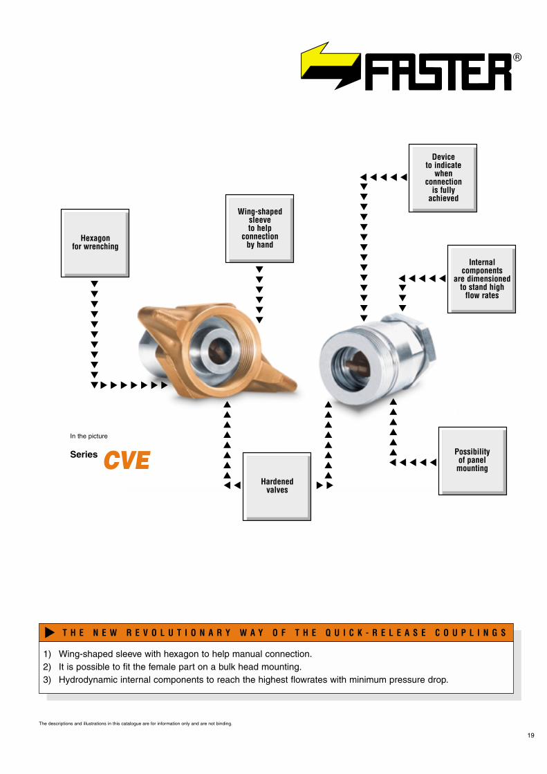
1) Wing-shaped sleeve with hexagon to help manual connection.2) It is possible to fit the female part on a bulk head mounting.3) Hydrodynamic internal components to reach the highest flowrates with minimum pressure drop.
T H E N E W R E V O L U T I O N A R Y W A Y O F T H E Q U I C K - R E L E A S E C O U P L I N G S
�
20
SeriesCVE
Patented
Pressure drop graph:Test bench to ISO 7241-2 specifìcations with oil viscosity 20 cSt (3°E), temperature 50°C (122°F).Materials:- In steel zinced with Cr III passivation- Sleeve in brass- Springs C 98Seals:Standard in oilproof NBR (Nitrile Rubber).On request: Viton, Neoprene, EPDM or other seals.Working temperatures:With standard seals in NBR (Nitrile Rubber) from -25°C (-13°F) to +125°C (+257°F).For temperature exceeding these values, the quick-release couplings will be supplied with all components in steel together with the appropriate seals.
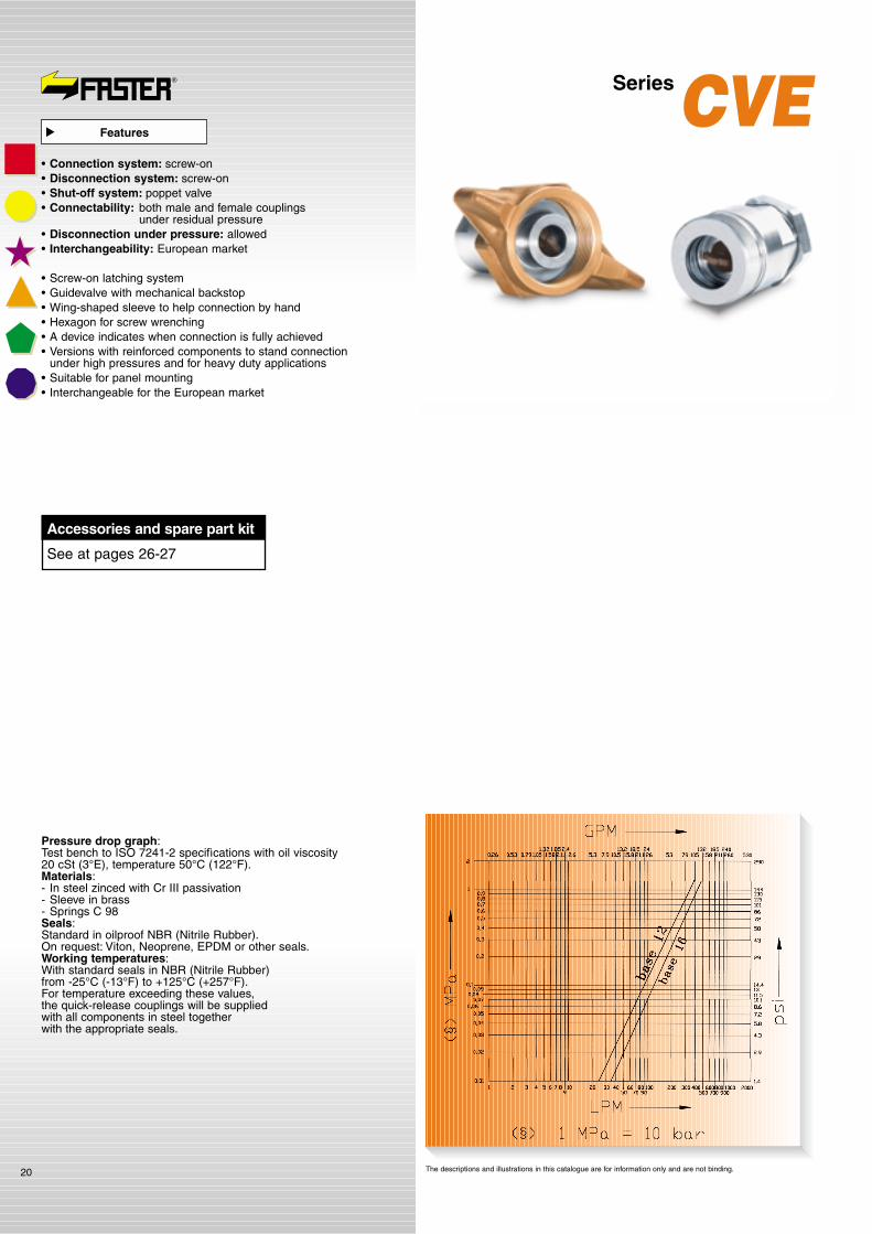
The descriptions and illustrations in this catalogue are for information only and are not binding.
Features
�
Accessories and spare part kit
See at pages 26-27
• Connection system: screw-on• Disconnection system: screw-on• Shut-off system: poppet valve• Connectability: both male and female couplings
under residual pressure• Disconnection under pressure: allowed• Interchangeability: European market
• Screw-on latching system• Guidevalve with mechanical backstop• Wing-shaped sleeve to help connection by hand• Hexagon for screw wrenching• A device indicates when connection is fully achieved• Versions with reinforced components to stand connection
under high pressures and for heavy duty applications• Suitable for panel mounting• Interchangeable for the European market
The descriptions and illustrations in this catalogue are for information only and are not binding.
21
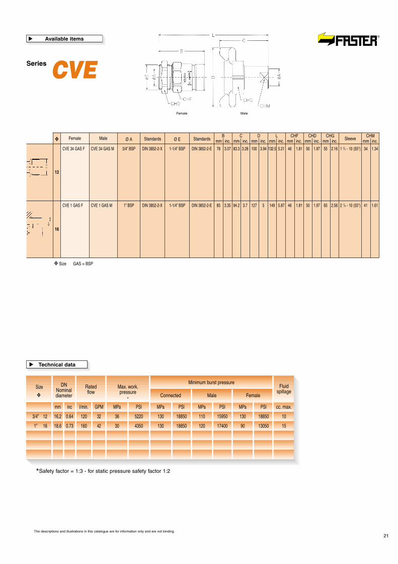
Female
CVE 34 GAS F CVE 34 GAS M 3/4” BSP DIN 3852-2-X 1-1/4” BSP DIN 3852-2-E 78 3.07 83.3 3.28 100 3.94 132.5 5.21 46 1.81 50 1.97 55 2.16 1 3/4 - 10 (55°) 34 1.34
CVE 1 GAS F CVE 1 GAS M 1” BSP DIN 3852-2-X 1-1/4” BSP DIN 3852-2-E 85 3.35 94.2 3.7 127 5 149 5.87 46 1.81 50 1.97 65 2.56 2 1/8 - 10 (55°) 41 1.61
Male Ø A
12
16
Ø EStandards StandardsB
mm inc.C
mm inc.D
mm inc.L
Sleevemm inc.CHF
mm inc.CHD
mm inc.CHG
mm inc.CHM
mm inc.❖
❖ Size GAS = BSP
Female Male
Series CVEAvailable items
�
*Safety factor = 1:3 - for static pressure safety factor 1:2
Size
mm l/min. MPa MPa MPaPSI PSI PSIGPM
Ratedflow
Max. work.pressure
Connected Male Female
Fluidspillage
cc. max.
Minimum burst pressure
3/4” 12
DNNominaldiameter
16,2 0.64 36 5220 130 18850 110 130 18850 1015950120 32
1” 16 18,6 0.73 30 4350 130 18850 120 90 13050 1517400160 42
inc MPa PSI
Technical data�
*❖

22
SeriesPVVMScrew-on couplings
for heavy duty service

���������
�����
�����
�����
�����
������
����
�����
����������
��
� �
� � � � � � � �
� � � � �
Hardenedvalves
Reinforcedinternal
components
Greatcross
section
Greatvalve
protrusion
Screw-onconnection
system
Metalto metalsealing
PTFEbackup
ring
Highresistance
valveseat
23
Series PVVM 38Patented
In the picture
The descriptions and illustrations in this catalogue are for information only and are not binding.
1) Very high resistance to static pressures.2) Connection and disconnection operations can be performed under pressure.3) Maximum flow rate is ensured even in case of a light unscrewing of the sleeve.4) Perfect interchangeability with similar couplings even if equipped with a ball valve.5) Safety factor 1:3, also when the coupling is diconnected.6) Wide range of male and female BSP-NPT and Metric threads.7) AISI 316 stainless steel couplings available on request.
T H E N E W R E V O L U T I O N A R Y W A Y O F T H E Q U I C K - R E L E A S E C O U P L I N G S
�
Pressure drop graph:Test bench to ISO 7241-2 specifìcations with oil viscosity 20 cSt (3°E), temperature 50°C (122°F).Materials:- Steel zinced with Cr III passivation- Steel hardened valves- Springs C 98Seals:Standard in oilproof NBR (Nitrile Rubber).On request: Viton, Neoprene, EPDM or other seals.Antiextrusion rings:In pure PTFE.Working temperatures:With standard seals in NBR (Nitrile Rubber) from -25°C (-13°F) to +125°C (+257°F).For temperature exceeding these values, the quick-release coupling will be supplied with all components in steel together with the appropriate seals.
24
SeriesPVVM
PatentedSteel Stainless steel
The descriptions and illustrations in this catalogue are for information only and are not binding.
• Connection system: screw-on• Disconnection system: screw-on• Shut-off system: poppet valve• Connectability: both male and female couplings under pressure• Disconnection under pressure: allowed• Interchangeability: European and US market
• Screw-on latching system• Dimensioned to stand very high static pressures• Metal to metal sealing• On request also available in Stainless Steel• Interchangeable for US and European market
Features
�
Accessories and spare part kit
See at pages 26-27
*Safety factor = 1:3 - for static pressure safety factor 1:2
Size
mm l/min. MPa MPa MPaPSI PSI PSIGPM
Ratedflow
Max. work.pressure
Connected Male Female
Fluidspillage
cc. max.
Minimum burst pressure
1/4” 04
DNNominaldiameter
4,1 0.16 105 15225 350 50750 310 330 47850 0,54495015 4
3/8” 06 5,5 0.22 100 14500 350 50750 290 300 43500 14205020 5,3
inc MPa PSI
Technical data
�
*❖

25
Female
PVVM14NPT M 1/4” NPTF ANSI B1.20.3 34 1.34 27 1.06
PVVM38NPT M 3/8” NPTF ANSI B1.20.3 39 1.53 32 1.26
PVVM1/14NPT F PVVM1/14NPT M 1/4” NPTF ANSI B1.20.3 62.8 2.47 55 2.16 1” - 18 UN 30 1.18 98.8 3.89 21 0.83 27 1.06PVVM1/14GAS F PVVM1/14GAS M 1/4” BSP DIN 3863 62.8 2.47 55 2.16 1” - 18 UN 30 1.18 98.8 3.89 21 0.83 27 1.06
PVVM38-1/14NPT F PVVM38-1/14NPT M 1/4” NPTF ANSI B1.20.3 83.3 3.28 64.8 2.55 1 3/16” - 16 UN 36 1.42 122.7 4.83 25 0.98 32 1.26PVVM38-1/14GAS F PVVM38-1/14GAS M 1/4” BSP DIN 3863 82.3 3.24 64.8 2.55 1 3/16” - 16 UN 36 1.42 122.7 4.83 25 0.98 32 1.26PVVM1/38NPT F PVVM1/38NPT M 3/8” NPTF ANSI B1.20.3 83.3 3.28 64.8 2.55 1 3/16” - 16 UN 36 1.42 122.7 4.83 25 0.98 32 1.26PVVM1/38GAS F PVVM1/38GAS M 3/8” BSP DIN 3863 83.3 3.28 64.8 2.55 1 3/16” - 16 UN 36 1.42 122.7 4.83 25 0.98 32 1.26
PVVM14-23/14G F PVVM14-23/14G M 1/4” BSP DIN 3852-2-B 66.5 2.62 55 2.16 1” - 18 UN 30 1.18 102.5 4.03 21 0.83 27 1.06
PVVM38-23/14G F PVVM38-23/14G M 1/4” BSP DIN 3852-2-B 82.3 3.24 63.8 2.51 1 3/16” - 16 UN 36 1.42 120.7 4.75 25 0.98 32 1.26
Male Ø A
04
*
*
**
*
* *
**
*
Bmm inc.
CSleevemm inc.
Ø Dmm inc.
Lmm inc.
CHFmm inc.
CHMmm inc.Standards
06
04
06
04
06
❖
❖ Size GAS = BSP *On request
The descriptions and illustrations in this catalogue are for information only and are not binding.
Male MaleFemale
Series PVVMAvailable items
�
Aluminium plugswith chain
Aluminium plugs withcoloured cord in PVC
AISI 316 stainlesssteel plugs
TMV14 S TFV14 SS
TMV38 S TMVM38 SBTMVM38 SGTMVM38 SNTMVM38 SRTMVM38 SV
TMV38 SS
TMV12 S TMVM12 SBTMVM12 SGTMVM12 SNTMVM12 SRTMVM12 SV
TMV12 SS
TMV34 S TMV34 SS
TMV1 S TMV1 SS
TMV114 S TMV114 SS
TMV112 S TMV112 SS
TMV2 S TMV2 SS
*
*
*
*
*
*
26
TFVM38 SR series
TMVM38 SR series
The descriptions and illustrations in this catalogue are for information only and are not binding.
Protections for male part Protections for female part
Aluminium capswith chain
Aluminium caps withcoloured cord in PVC
AISI 316stainless steel
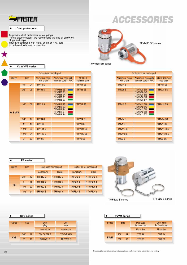
Series Size
TFV14 S TFV14 SS
VV & VVS
1/4” 04
TFV38 S TFVM38 SBTFVM38 SGTFVM38 SNTFVM38 SRTFVM38 SV
TFV38 SS3/8” 06
VV & VVS series
�
FB series
�
ACCESSORIES
TFV12 S TFVM12 SBTFVM12 SGTFVM12 SNTFVM12 SRTFVM12 SV
TFV12 SS1/2” 08
TFV34 S TFV34 SS3/4” 12
TFV1 S TFV1 SS1” 16
TFV114 S TFV114 SS1 1/4” 20
TFV112 S TFV112 SS1 1/2” 24
TFV2 S TFV2 SS2” 32
*
*
*
*
*
*
Dust caps for male part Dust plugs for female part
Aluminium Brass Aluminium Brass
Series Size
TFFB12 S TFFB12 5 TMFB12 S TMFB12 5
FB
3/4” 12
TFFB16 S TFFB16 5 TMFB16 S TMFB16 51” 16
TFFB20 S TFFB20 5 TMFB20 S TMFB20 51 1/4” 20
TFFB24 S TFFB24 5 TMFB24 S TMFB24 51 1/2” 24
*
*
*
*
*
*
*
* **
Dust capsfor male part
Dust plugsfor female part
Aluminium Aluminium
Series Size
TFP 14 TMP 14PVVM
1/4” 04
TFP 38 TMP 383/8” 06
Dustplug
Dustcap
Aluminium Aluminium
Series Size
TM CVE34 S TF CVE34 SCVE
3/4” 12
TM CVE1 S TF CVE1 S1” 16
TMFB20 S series TFFB20 S series
To provide dust protection for couplings- once disconnected - we recommend the use of screw-onplugs and caps.They are equipped with metal chain or PVC cordto be linked to hoses or machine.
Dust protections
�
CVE series
�
PVVM series
�

27The descriptions and illustrations in this catalogue are for information only and are not binding.
Series Size Kit code
KIT VV14
VV
1/4” 04
KIT VV383/8” 06
KIT VV121/2” 08
KIT VV343/4” 12
KIT VV11” 16
KIT VVS14
VVS
1/4” 04
KIT VVS383/8” 06
KIT VVS121/2” 08
KIT VVS343/4” 12
KIT VVS11” 16
KIT VVS1141 1/4” 20
KIT VVS1121 1/2” 24
KIT VVS22” 32
KIT FB12
FB
3/4” 12
KIT FB161” 16
KIT FB201 1/4” 20
KIT FB241 1/2” 24
KIT CVE34CVE
3/4” 12
KIT CVE11” 16
KIT PVV14PVVM
1/4” 04
KIT PVV383/8” 06
ACCESSORIESWhen seals are damaged due to wear of foreign material,it is necessary to replace them.Original FASTER® spare parts kits are now available.Detailed instructions are included to achieve the correctreplacement of damaged parts.No special tools are required to carry out replacement.For seal changing do not use sharpened tools that coulddamage the new seals or the coupling itself.
Spare parts kit
�

Screw-on couplings CVV series
��
���
���
����������
� �
��
���������
�������
�����
� � � �
Frictionring
Hydrodynamicinternal
components
Widerange
of threads
Hardenedvalve
bodies
� � � �
Shapedsleeve
for screwwrench
PTFEbackup
ring
28
The descriptions and illustrations in this catalogue are for information only and are not binding.
1) The wide range of BSP, METRIC, NPT, SAE threads allows customer to fit the product to its needs, saving extra-cost for adaptors.
2) The valves are manufactured following the classic FASTER® method:induction hardened to avoid dents, equipped with special profiled anti-extrusion seal.
3) Special design of internal components minimizes pressure drops.4) Couplings with internal components completely made of steel and with Viton seals are available on request.5) Threaded sleeve with friction ring.
T H E N E W R E V O L U T I O N A R Y W A Y O F T H E Q U I C K - R E L E A S E C O U P L I N G S
�
Series
For further information and technical details please ask for the specific catalogue: CPV-CNV and CVV series n° 0116.
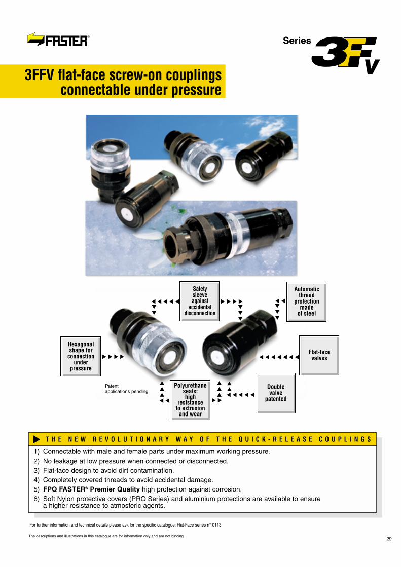
Series
29
For further information and technical details please ask for the specific catalogue: Flat-Face series n° 0113.
The descriptions and illustrations in this catalogue are for information only and are not binding.
��
���
���
��
���
���
����������
� �
��
�������
������������
� � � �
Flat-facevalves
Automaticthread
protectionmade
of steel
Safetysleeveagainst
accidentaldisconnection
Polyurethaneseals:high
resistanceto extrusion
and wear
� � � �
Hexagonalshape for
connectionunder
pressure
Doublevalve
patented
Patent applications pending
3FFV flat-face screw-on couplingsconnectable under pressure
1) Connectable with male and female parts under maximum working pressure.2) No leakage at low pressure when connected or disconnected.3) Flat-face design to avoid dirt contamination.4) Completely covered threads to avoid accidental damage.5) FPQ FASTER® Premier Quality high protection against corrosion.6) Soft Nylon protective covers (PRO Series) and aluminium protections are available to ensure
a higher resistance to atmosferic agents.
T H E N E W R E V O L U T I O N A R Y W A Y O F T H E Q U I C K - R E L E A S E C O U P L I N G S
�
30
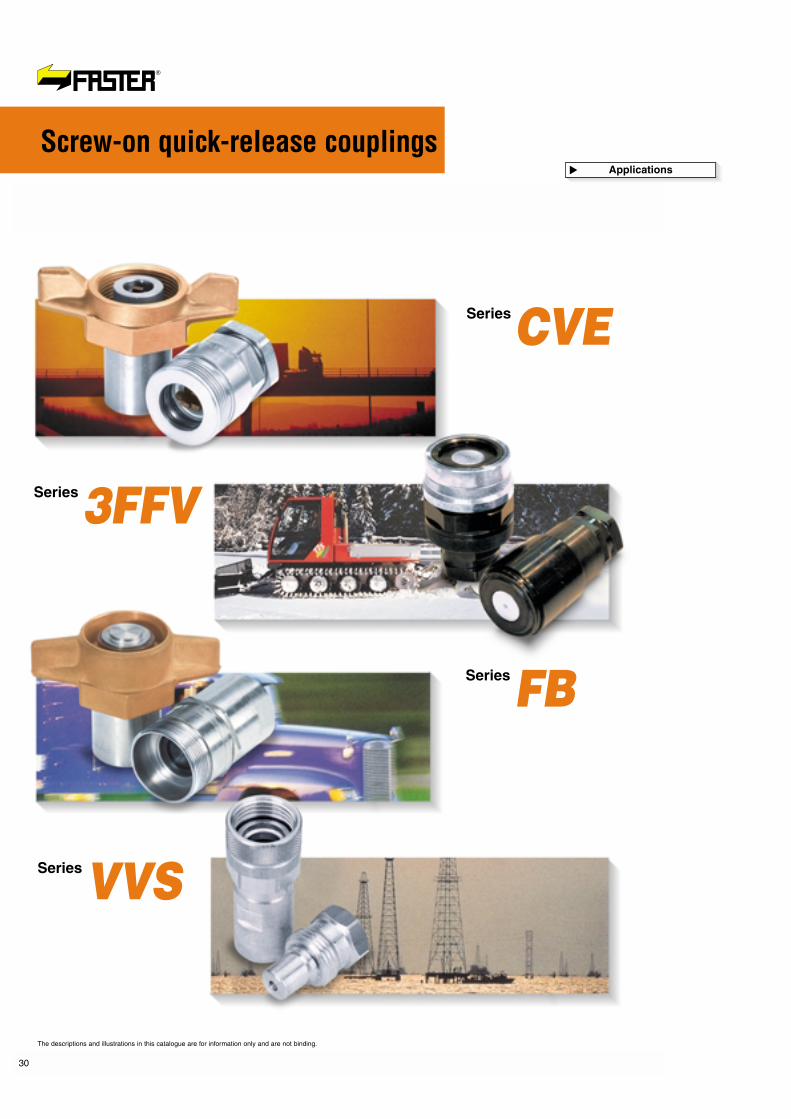
SeriesCVE
Series3FFV
SeriesFB
SeriesVVS
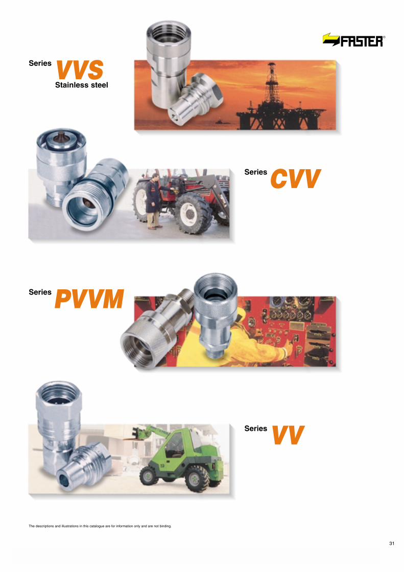
Applications
�
Screw-on quick-release couplings
The descriptions and illustrations in this catalogue are for information only and are not binding.
The descriptions and illustrations in this catalogue are for information only and are not binding.
SeriesCVV
SeriesVVSStainless steel
SeriesPVVM
SeriesVV
31

UNI EN ISO 9001Cert. n° 2905ISO/TS 16949
I - FASTER S.p.A.I-26027 RIVOLTA D’ADDA (CR) Italy - Via L. Ariosto, 7
(+39) 0363.377211 - Fax (+39) 0363.377333www.faster.it - [email protected]
D-BENELUX - FASTER - Jürgen GamersD-40764 LANGENFELD GER - Ursulaweg, 39
(+49) (0) 2173.83924 - Fax (+49) (0) 2173.83925www.faster-germany.de - [email protected]
UK - FASTER - Richard BennettGB-TA18 7BY UK19 Beechwood Drive CREWKERNE, Somerset
(+44) (0) 1460.77020 - Fax (+44) (0) [email protected]
F - FASTER - François DivetF-35200 RENNES - 11, Rue Jean Bras
(+33) (0) 2.99.51.44.94Fax (+33) (0) [email protected]
USA - FASTER Inc.MAUMEE, OH 43537-9505 - 6560 Weatherfield, Ct.
(+1) 419-868-8197 - (+1) 800-231-2501 - Fax (+1) 419-868-8360www.fasterinc.com - [email protected]
All FASTER® quick-releasecouplings are designed andproduced in conformity withthe regulations of QualityManaging System accordingto UNI EN ISO 9001and UNI ISO/TS 16949Standards.They bear the FASTER® logoto guarantee their origin andreliability.FASTER® quick-releasecouplings are distributedworldwide through a networkof highly qualified distributors.
Guarantee
�
Ask for our catalogues
CAT. 0113-I ItalianoCAT. 0113-GB EnglishFF Flat-Face series
CAT
0114
/09/
06-G
B
CAT. 0112-I ItalianoCAT. 0112-GB EnglishAgriculture series
CAT. 0111-I ItalianoCAT. 0111-GB EnglishMultifaster series
CAT. 0110/I ItalianoCAT. 0110/GB EnglishCAT. 0110/F FrançaisGeneral Line
CAT. 0116-I ItalianoCAT. 0116-GB EnglishCPV-CNV and CVV series
CAT. 0115-I ItalianoCAT. 0115-GB EnglishStandard series
CAT. 0114-I ItalianoCAT. 0114-GB EnglishScrew-on coupling series
CAT. 0117-I ItalianoCAT. 0117-GB EnglishDF series
CAT. 0118-I ItalianoCAT. 0118-GB EnglishRF series
CAT. 0119-I ItalianoCAT. 0119-GB EnglishVU series
CAT. 0120-I ItalianoCAT. 0120-GB EnglishIndustrial series


![refrigerant for Industrial Refrigeration - OMNICO Engineeringomnico-engineering.com/Danfoss-CO2_Refrigerant_for_Industrial... · essu re [b ar] Pressure [psi] [bar] 14500 1000 145](https://img.pdfslide.us/doc/110x75/5aaea61e7f8b9a190d8c61c5/refrigerant-for-industrial-refrigeration-omnico-engineeringomnico-re-b-ar-pressure.jpg)