Embed Size (px)
Citation preview
CL-VRR SERIES
VARIABLE AIRFLOW RECTANGULAR REGULATORS
OVERVIEW
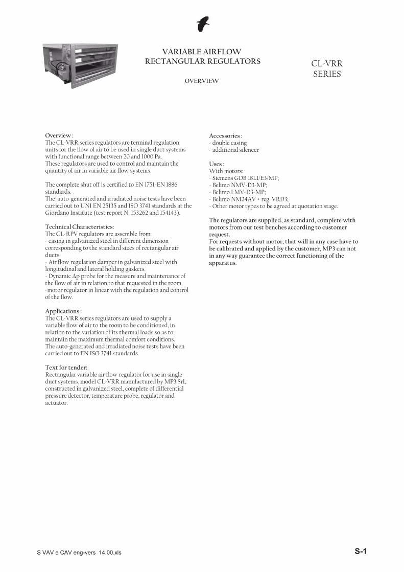
Overview :The CL-VRR series regulators are terminal regulation units for the flow of air to be used in single duct systems with functional range between 20 and 1000 Pa.These regulators are used to control and maintain the quantity of air in variable air flow systems.
The complete shut off is certified to EN 1751-EN 1886 standards.The auto-generated and irradiated noise tests have been carried out to UNI EN 25135 and ISO 3741 standards at the Giordano Institute (test report N. 153262 and 154143).
Technical Characteristics:The CL-RPV regulators are assemble from: - casing in galvanized steel in different dimension corresponding to the standard sizes of rectangular air ducts.- Air flow regulation damper in galvanized steel with longitudinal and lateral holding gaskets. - Dynamic �p probe for the measure and maintenance of the flow of air in relation to that requested in the room.-motor regulator in linear with the regulation and control
f h fl
Accessories : - double casing- additional silencer
Uses :With motors:- Siemens GDB 181.1/E3/MP;- Belimo NMV-D3-MP; - Belimo LMV-D3-MP; - Belimo NM24AV + reg. VRD3; - Other motor types to be agreed at quotation stage.
The regulators are supplied, as standard, complete with motors from our test benches according to customer request. For requests without motor, that will in any case have to be calibrated and applied by the customer, MP3 can not in any way guarantee the correct functioning of the apparatus.
of the flow.
Applications : The CL-VRR series regulators are used to supply a variable flow of air to the room to be conditioned, in relation to the variation of its thermal loads so as to maintain the maximum thermal comfort conditions. The auto-generated and irradiated noise tests have been carried out to EN ISO 3741 standards.
Text for tender: Rectangular variable air flow regulator for use in single duct systems, model CL-VRR manufactured by MP3 Srl, constructed in galvanized steel, complete of differential pressure detector, temperature probe, regulator and actuator.
S VAV e CAV eng-vers 14.00.xls S-1
CL-VRR SERIES
WORKING PRINCIPLE
VARIABLE AIRFLOW RECTANGULAR REGULATORS
WORKING PRINCIPLE “INDEPENDENT PRESSURE”
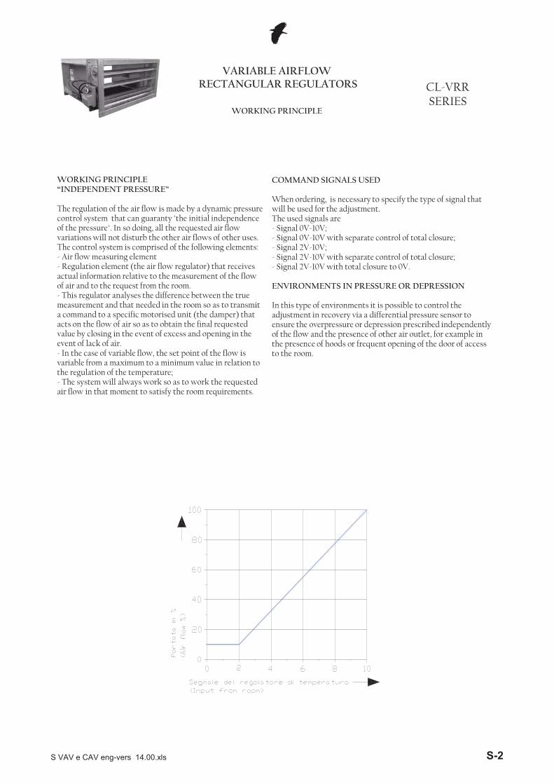
The regulation of the air flow is made by a dynamic pressure control system that can guaranty "the initial independence of the pressure". In so doing, all the requested air flow variations will not disturb the other air flows of other uses.The control system is comprised of the following elements:- Air flow measuring element- Regulation element (the air flow regulator) that receives actual information relative to the measurement of the flow of air and to the request from the room.- This regulator analyses the difference between the true measurement and that needed in the room so as to transmit a command to a specific motorised unit (the damper) that acts on the flow of air so as to obtain the final requested value by closing in the event of excess and opening in the event of lack of air.- In the case of variable flow, the set point of the flow is variable from a maximum to a minimum value in relation to the regulation of the temperature;- The system will always work so as to work the requested air flow in that moment to satisfy the room requirements.
COMMAND SIGNALS USED
When ordering, is necessary to specify the type of signal that will be used for the adjustment.The used signals are- Signal 0V-10V;- Signal 0V-10V with separate control of total closure;- Signal 2V-10V;- Signal 2V-10V with separate control of total closure;- Signal 2V-10V with total closure to 0V.
ENVIRONMENTS IN PRESSURE OR DEPRESSION
In this type of environments it is possible to control the adjustment in recovery via a differential pressure sensor to ensure the overpressure or depression prescribed independently of the flow and the presence of other air outlet, for example in the presence of hoods or frequent opening of the door of access to the room.
S VAV e CAV eng-vers 14.00.xls S-2
WORKING PRINCIPLE
CL-VRR SERIES
VARIABLE AIRFLOW RECTANGULAR REGULATORS
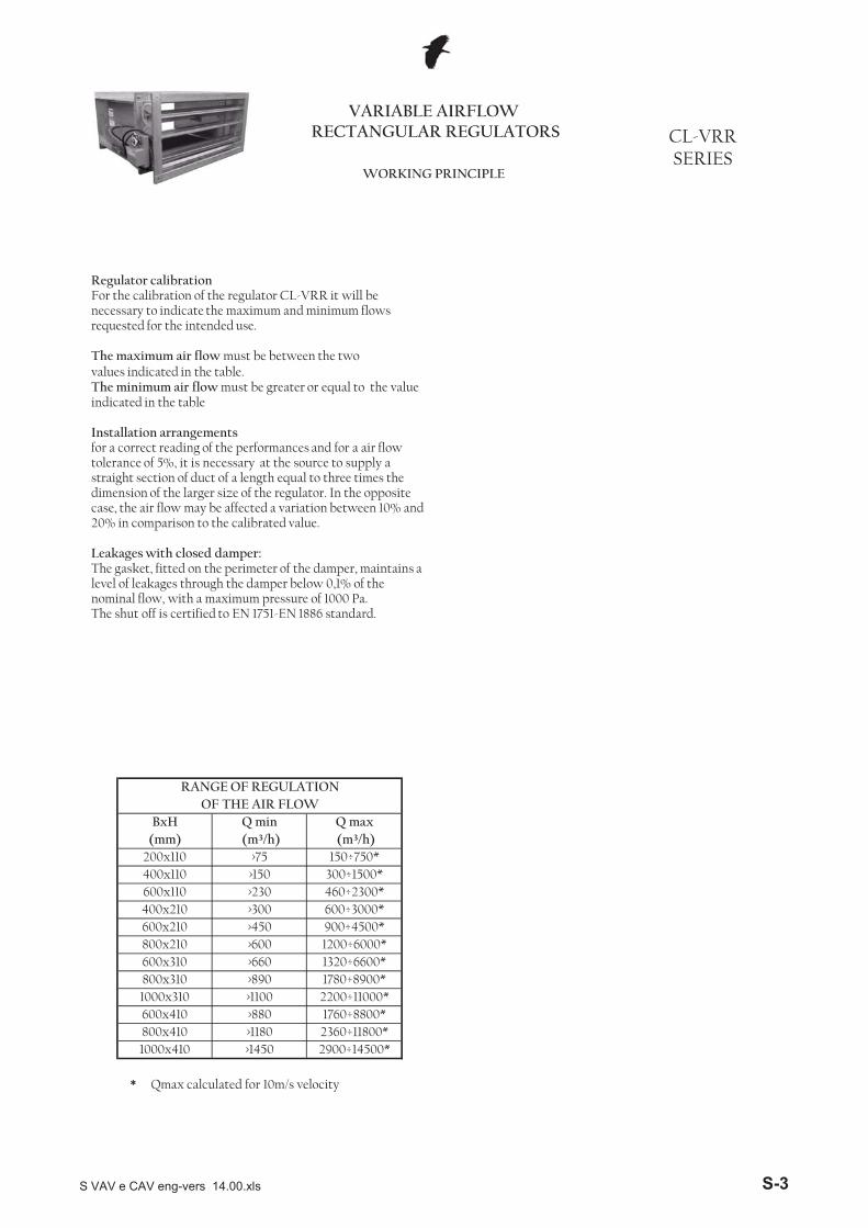
Regulator calibrationFor the calibration of the regulator CL-VRR it will be necessary to indicate the maximum and minimum flows requested for the intended use.
The maximum air flow must be between the two values indicated in the table.The minimum air flow must be greater or equal to the value indicated in the table
Installation arrangementsfor a correct reading of the performances and for a air flow tolerance of 5%, it is necessary at the source to supply a straight section of duct of a length equal to three times the dimension of the larger size of the regulator. In the opposite case, the air flow may be affected a variation between 10% and 20% in comparison to the calibrated value.
Leakages with closed damper:The gasket, fitted on the perimeter of the damper, maintains a level of leakages through the damper below 0,1% of the nominal flow, with a maximum pressure of 1000 Pa.The shut off is certified to EN 1751-EN 1886 standard.
*
RANGE OF REGULATIONOF THE AIR FLOW
1000x410800x410600x410
800x310600x310
>1450
400x110
800x210
400x210600x110
>450
200x110
1000x310
>230>300
>890
600x210
>75(mm)BxH Q max
(m³/h)Q min (m³/h)
>150
>600>660
150÷750*300÷1500*460÷2300*600÷3000*900÷4500*1200÷6000*
Qmax calculated for 10m/s velocity
1320÷6600*1780÷8900*
2200÷11000*1760÷8800*2360÷11800*2900÷14500*
>1180
>1100>880
S VAV e CAV eng-vers 14.00.xls S-3
25600x410 5280 6 62 69 77
351760 2 55 66 74 206600 10 62 70 78
20600x310 3960 6 58 67 75 25
1320 2 57 63 70
254500 10 63 71 79 35
600x210 2700 6 60 69 76
35900 2 54 63 69 20
2300 10 61 72 78
20600x110 1380 6 59 68 75 25
460 2 57 62 69
dBa �pmin(mm) (m³/h) (m/s) �P=200 Pa �P=500 Pa �P=1000 Pa (Pa)
VARIABLE AIRFLOW RECTANGULAR REGULATORS CL-VRR
SERIESTECHNICAL DATA
GENERATED NOISE AND AIR FLOW LOSS
BxH Air flow Speed dBa dBa
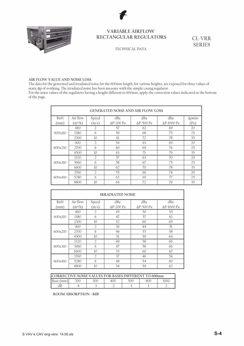
AIR FLOW VALUE AND NOISE LOSSThe data for the generated and irradiated noise for the 600mm length, for various heights, are exposed for three values of static �p of working. The irradiated noise has been measure with the simple casing regulator.For the noise values of the regulators having a height different to 600mm, apply the correction values indicated at the bottom of the page.
2dB -4 -3 -2 -1 1
CORRECTIVE NOISE VALUES FOR BASES DIFFERENT TO 600mm Base (mm) 200 300 400 500 800 1000
8800 10 54 59 62600x410 5280 6 48 54 60
1760 2 37 46 546600 10 53 60 67
600x310 3960 6 47 58 661320 2 49 58 664500 10 51 59 64
600x210 2700 6 46 53 58900 2 36 44 51
2300 10 52 60 65600x110 1380 6 47 57 63
460 2 45 50 55(mm) (m³/h) (m/s) �P=200 Pa �P=500 Pa �P=1000 Pa
IRRADIATED NOISE
BxH Air flow Speed dBa dBa dBa
258800 10 64 72 79 35
600x410 5280 6 62 69 77
ROOM ABSORPTION: -8dB
S VAV e CAV eng-vers 14.00.xls S-4
VARIABLE AIRFLOW RECTANGULAR REGULATORS CL-VRR
SERIESSTANDARD SIZES
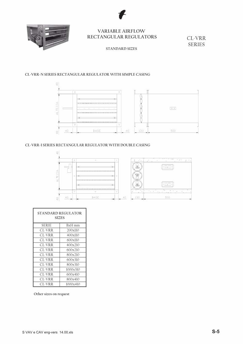
CL-VRR-N SERIES RECTANGULAR REGULATOR WITH SIMPLE CASING
CL-VRR-I SERIES RECTANGULAR REGULATOR WITH DOUBLE CASING
Other sizes on request
CL-VRR 600x410CL-VRR 800x410CL-VRR 1000x410
CL-VRR 600x310CL-VRR 800x310CL-VRR 1000x310
CL-VRR 400x210CL-VRR 600x210CL-VRR 800x210
CL-VRR 400x110CL-VRR 600x110
STANDARD REGULATOR SIZES
SERIE BxH mmCL-VRR 200x110
S VAV e CAV eng-vers 14.00.xls S-5
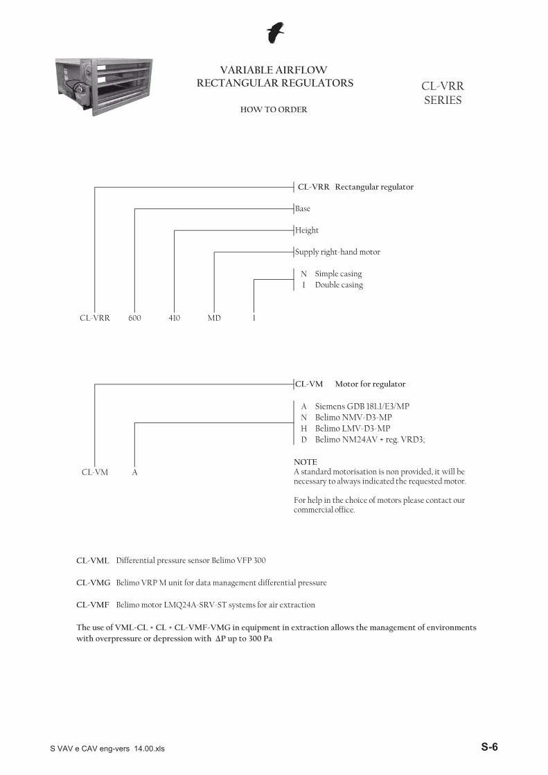
NI
CL-VM Motor for regulator
Double casing
CL-VRR 600 410 MD I
CL-VRR Rectangular regulator
Base
Height
Supply right-hand motor
Simple casing
VARIABLE AIRFLOW RECTANGULAR REGULATORS CL-VRR
SERIESHOW TO ORDER
ANHD
with overpressure or depression with �P up to 300 Pa
CL-VML Differential pressure sensor Belimo VFP 300
CL-VMG Belimo VRP M unit for data management differential pressure
CL-VMF Belimo motor LMQ24A-SRV-ST systems for air extraction
The use of VML-CL + CL + CL-VMF-VMG in equipment in extraction allows the management of environments
Belimo LMV-D3-MPBelimo NM24AV + reg. VRD3;
CL-VM A
Siemens GDB 181.1/E3/MPBelimo NMV-D3-MP
NOTEA standard motorisation is non provided, it will be necessary to always indicated the requested motor.
For help in the choice of motors please contact our commercial office.
S VAV e CAV eng-vers 14.00.xls S-6
CL-VRC SERIES
CIRCULAR REGULATORS WITH VARIABLE AIR FLOW
OVERVIEW
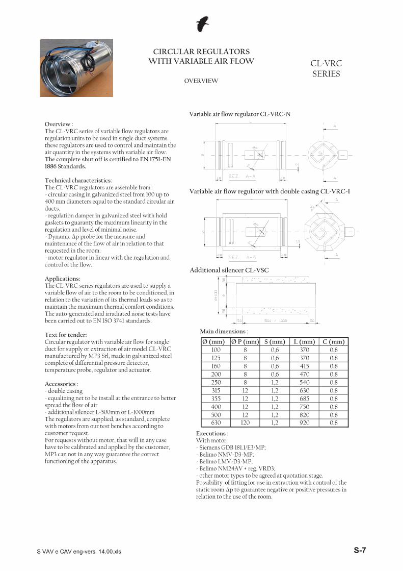
Variable air flow regulator CL-VRC-N
Overview :The CL-VRC series of variable flow regulators are regulation units to be used in single duct systems.these regulators are used to control and maintain the air quantity in the systems with variable air flow.The complete shut off is certified to EN 1751-EN 1886 Standards.
Technical characteristics:The CL-VRC regulators are assemble from: - circular casing in galvanized steel from 100 up to 400 mm diameters equal to the standard circular air ducts.- regulation damper in galvanized steel with hold gaskets to guaranty the maximum linearity in the regulation and level of minimal noise.- Dynamic �p probe for the measure and maintenance of the flow of air in relation to that requested in the room.- motor regulator in linear with the regulation and control of the flow.
Applications:The CL-VRC series regulators are used to supply a variable flow of air to the room to be conditioned, in
Variable air flow regulator with double casing CL-VRC-I
Additional silencer CL-VSC
Ø (mm)
500 12 1,2 820 0,8630 120 1,2 920 0,8
100 8 0,6 370 0,8
0,81,23151,2
125
0,80,8
0,80,80,80,8
1,21,2
370415470540630685750
0,6
355400
8121212
250
160200
888
0,60,6
L (mm) C (mm)Ø P (mm) S (mm)
variable flow of air to the room to be conditioned, in relation to the variation of its thermal loads so as to maintain the maximum thermal comfort conditions. The auto-generated and irradiated noise tests have been carried out to EN ISO 3741 standards.
Text for tender:Circular regulator with variable air flow for single duct for supply or extraction of air model CL-VRC manufactured by MP3 Srl, made in galvanized steel complete of differential pressure detector, temperature probe, regulator and actuator.
Accessories : - double casing - equalizing net to be install at the entrance to better spread the flow of air- additional silencer L=500mm or L=1000mmThe regulators are supplied, as standard, complete with motors from our test benches according to customer request. For requests without motor, that will in any case have to be calibrated and applied by the customer, MP3 can not in any way guarantee the correct functioning of the apparatus.
Main dimensions :
Executions :With motor:- Siemens GDB 181.1/E3/MP;- Belimo NMV-D3-MP; - Belimo LMV-D3-MP; - Belimo NM24AV + reg. VRD3; - other motor types to be agreed at quotation stage.Possibility of fitting for use in extraction with control of the static room �p to guarantee negative or positive pressures in relation to the use of the room.
S VAV e CAV eng-vers 14.00.xls S-7
CL-VRC SERIES
WORKING PRINCIPLES
CIRCULAR REGULATORS WITH VARIABLE AIR FLOW
WORKING PRINCIPLE “INDEPENDENT PRESSURE”
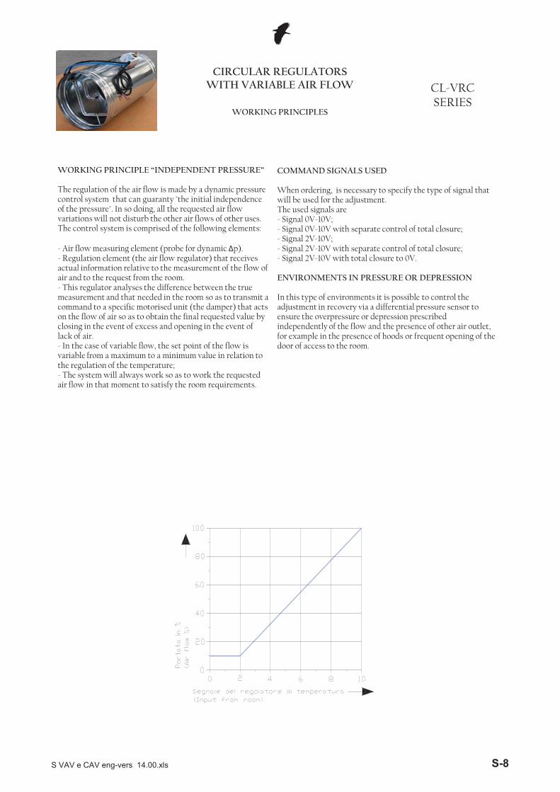
The regulation of the air flow is made by a dynamic pressure control system that can guaranty "the initial independence of the pressure". In so doing, all the requested air flow variations will not disturb the other air flows of other uses.The control system is comprised of the following elements:
- Air flow measuring element (probe for dynamic �p).- Regulation element (the air flow regulator) that receives actual information relative to the measurement of the flow of air and to the request from the room.- This regulator analyses the difference between the true measurement and that needed in the room so as to transmit a command to a specific motorised unit (the damper) that acts on the flow of air so as to obtain the final requested value by closing in the event of excess and opening in the event of lack of air.- In the case of variable flow, the set point of the flow is variable from a maximum to a minimum value in relation to the regulation of the temperature;- The system will always work so as to work the requested air flow in that moment to satisfy the room requirements.
COMMAND SIGNALS USED
When ordering, is necessary to specify the type of signal that will be used for the adjustment.The used signals are- Signal 0V-10V;- Signal 0V-10V with separate control of total closure;- Signal 2V-10V;- Signal 2V-10V with separate control of total closure;- Signal 2V-10V with total closure to 0V.
ENVIRONMENTS IN PRESSURE OR DEPRESSION
In this type of environments it is possible to control the adjustment in recovery via a differential pressure sensor to ensure the overpressure or depression prescribed independently of the flow and the presence of other air outlet, for example in the presence of hoods or frequent opening of the door of access to the room.
S VAV e CAV eng-vers 14.00.xls S-8
PERFORMANCE
CIRCULAR REGULATORS WITH VARIABLE AIR FLOW CL-VRC
SERIES
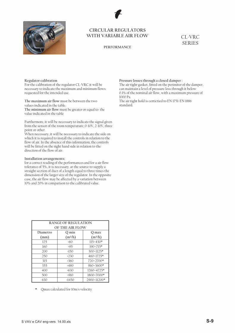
Regulator calibrationFor the calibration of the regulator CL-VRC it will be necessary to indicate the maximum and minimum flows requested for the intended use.
The maximum air flow must be between the two values indicated in the table.The minimum air flow must be greater or equal to the value indicated in the table
Furthermore, it will be necessary to indicate the signal given from the sensor of the room temperature; 0-10V, 2-10V, three point or other.When necessary, it will be necessary to indicate the side on which it is required to install the controls in relation to the flow of air. In the absence of this information, the controls will be fitted on the right hand side in relation to the direction of the flow of air.
Installation arrangements:for a correct reading of the performances and for a air flow tolerance of 5%, it is necessary at the source to supply a straight section of duct of a length equal to three times the
Pressure losses through a closed damper :The air tighr gasket, fitted on the perimiter of the damper, can maintain a level of pressure loss through it below 0.1% of the nominal air flow, with a maximum pressure of 1000 Pa.The air tight hold is certictied to EN 1751-EN 1886 standard.
* Qmax calculated for 10m/s velocity
200 >150 300÷1125*
355 >480 960÷3600*315 >360 720÷2700*
>60(mm) (m³/h) (m³/h)
RANGE OF REGULATIONOF THE AIR FLOW
Diametro Q min Q max
125
>230 460÷1725*
160 >95 190÷715*115÷430*
250
>910 1800÷7000*630 >1450 2900÷11200*
400 >630 1260÷4725*500
straight section of duct of a length equal to three times the dimension of the larger size of the regulator. In the opposite case, the air flow may be affected by a variation between 10% and 20% in comparison to the calibrated value.
S VAV e CAV eng-vers 14.00.xls S-9
Ø �Pmm Pa
64 59 756668 64 62 57 72
570 66 67 71 73 71400
60 57 53 68220 58 57 61 64 641000
60 47 45 48 53
67 6963 63
5264 59 56 49 69
48 46 5955
47 66570 62 64 67 67400 59 60 61 57 53
57 53 49 44 6137 52
220 54 54 57 5848
500
60 44 42 44 47
63 64
45 4050 44 36 60
57570 58 60 61 60 54400 55 56 58 56 51 47 42 34
31 5343
220 50 50 52 51 4839 39 39 36 29
44 38
2000 4000
23
8000 dBa
125
200
60 41 38
63 125 250 500 1000
Q Sound power (Lw-db/ott.)m³/h frequency(Hz)
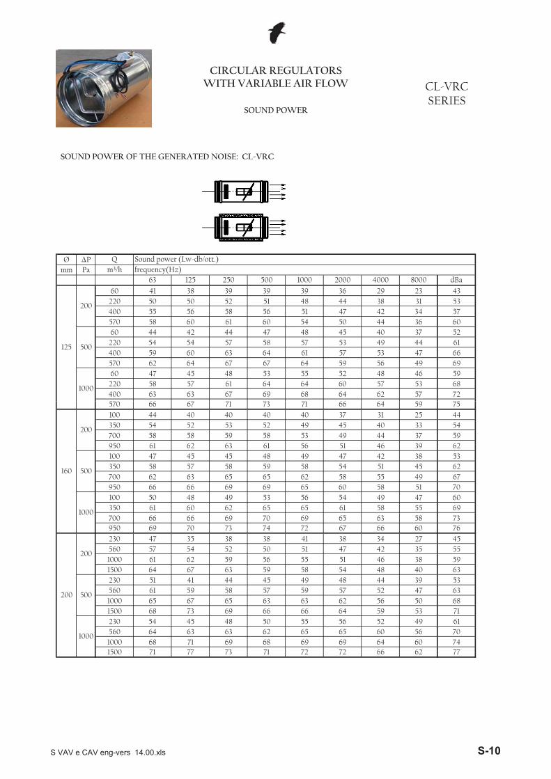
CIRCULAR REGULATORS WITH VARIABLE AIR FLOW CL-VRC
SERIESSOUND POWER
SOUND POWER OF THE GENERATED NOISE: CL-VRC
72 66 62 7774
1500 71 77 73 71 721000 68 71 69 68 69 69 64 60
65 60 56 70560 64 63 63 62 651000
230 54 45 48 50 5666 64 59 53 71
52 49 6155
50 681500 68 73 69 661000 65 67 63 62 56
59 57 52 47 6339 53
560 61 59 58 5749
500
230 51 41 44 45
65 63
48 4454 48 40 6363 59 58
1000 61 62 56 55 51 46 38 5947 42 35 55560 57 54 52 50 51
200
200
230 47 35 38
591500 64 67
66 60 7634 27 4541 38
6738
69 65 63 58 73950 69 70 73 74 72700
61 58 55 69350 61 60 62 65 651000
100 50 48 49 53
69 7066 66
5465 60 58 51 70
49 47 6056
49 67950 66 66 69 69700 62 63 62 58 55
58 54 51 45 6238 53
350 58 57 58 5949
500
100 47 45 45 48
65 65
47 4251 46 39 6263 61 56
700 58 58 58 53 49 44 37 5945 40 33 54350 54 52 53 52 49
160
200
100 44 40 40
59950 61 62
64 59 7531 25 4440 37
6640
570 66 67 71 73 71
S VAV e CAV eng-vers 14.00.xls S-10

Ø �Pmm Pa
66 62 60 58 7165 62 59 54 70
3600 75 72 71 69
61 58 55 50 662500 72 70 68 67
51 50 45 43 561500 67 64 61 62
55 52 45 65
500
400 56 51 47 49
53 50 43 633600 70 68 66 64 59
49 46 40 582500 67 65 62 61 571500 63 59 56 55 53
43 44 41 37 32 4872 67 61 78
315
200
400 52 46 42
69 65 59 762300 76 76 74 74 73
65 59 56 721600 73 74 73 73 71900 67 68 68 67 68
56 61 56 48 48 6366 64 61 54 72
1000
250 55 56 56
64 61 57 51 692300 73 73 71 70
61 57 52 48 651600 69 69 68 67
53 48 40 40 56900 64 64 62 62
54 51 43 64
500
250 52 52 51 50
51 48 41 612300 68 67 64 62 57
47 42 37 561600 65 64 61 59 55
38 30 29 47900 59 58 55 54 51
8000 dBa
250
200
250 47 46 44 42 44
m³/h frequency(Hz)63 125 250 500 1000 2000 4000
Q Sound power (Lw-db/ott.)
CIRCULAR REGULATORS WITH VARIABLE AIR FLOW CL-VRC
SERIESSOUND POWER
SOUND POWER OF THE GENERATED NOISE: CL-VRC
72 69 67 8070 67 65 77
6300 82 79 76 75 75
66 62 61 724400 78 75 72 72 732500 71 70 66 66 68
54 58 58 52 52 6369 65 63 60 74
1000
700 55 58 53
66 63 61 57 716300 80 75 71 71
62 59 56 53 664400 76 71 68 67
52 52 46 44 572500 69 66 62 62
56 55 50 67
500
700 53 53 49 50
54 52 47 636300 77 69 66 65 61
52 50 44 624400 72 66 62 61 582500 65 63 55 59 58
44 44 43 38 34 4972 67 66 79
400
200
700 50 48 43
68 67 66 774800 79 77 77 76 74
66 62 61 723300 75 75 73 73 731800 70 69 67 67 67
55 58 56 52 53 6268 64 62 56 73
1000
500 58 56 52
66 66 57 56 724800 75 74 72 71
61 58 55 50 663300 72 74 67 70
52 53 44 44 571800 67 64 61 62
55 52 45 65
500
500 56 53 46 51
53 50 43 634800 70 68 66 64 59
48 48 42 603300 67 65 62 61 571800 63 62 56 58 57
42 45 42 39 33 4971 68 65 79
355
200
500 52 45 44
69 66 63 763600 78 78 76 75 75
65 61 59 722500 75 74 72 72 721500 70 68 66 66 68
54 58 57 51 52 6266 62 60 58 71
1000
400 59 55 513600 75 72 71 69
S VAV e CAV eng-vers 14.00.xls S-11

Ø �Pmm Pa
68 65 62 57 7364 61 58 53 69
10100 75 73 71 70
54 53 48 46 595600 70 67 64 65
58 55 48 68
500
1600 59 54 50 52
56 53 46 6614600 73 71 69 67 62
52 49 43 6110100 70 68 65 64 605600 66 62 59 58 56
46 47 44 40 35 5176 71 65 82
630
200
1600 55 49 45
73 69 63 807400 80 80 78 78 77
69 63 60 765200 77 78 77 77 752900 71 72 72 71 72
60 65 60 52 52 6770 68 65 58 76
1000
800 59 60 60
68 65 61 55 737400 77 77 75 74
65 61 56 52 695200 73 73 72 71
57 52 44 44 602900 68 68 66 66
58 55 47 68
500
800 56 56 55 54
55 52 45 657400 72 71 68 66 61
51 46 41 605200 69 68 65 63 59
42 34 33 512900 63 62 59 58 55
8000 dBa
500
200
800 51 50 48 46 48
m³/h frequency(Hz)63 125 250 500 1000 2000 4000
Q Sound power (Lw-db/ott.)
CIRCULAR REGULATORS WITH VARIABLE AIR FLOW CL-VRC
SERIESSOUND POWER
SOUND POWER OF THE GENERATED NOISE: CL-VRC
74 71 68 8272 69 66 79
14600 81 81 79 78 78
68 64 62 7510100 78 77 75 75 755600 73 71 69 69 71
57 61 60 54 55 6569 65 63 61 74
1000
1600 62 58 5414600 78 75 74 72
S VAV e CAV eng-vers 14.00.xls S-12
Ø �Pmm Pa
56 52 665859 56 54 50 63
570 42 51 56 61 62400
52 49 46 59220 34 41 46 52 551000
60 23 29 33 41
52 5739 47
4455 51 48 42 59
40 39 5046
40 56570 38 48 52 55400 35 44 48 52 52 49 45
48 45 41220 30 38 42 463926 29 35
37 5230 4337 32
42 36 29 5027 4739 34
570 34 44 46 48 45400 31
3943 44 42
2736 30 24 43220 26 34 37 39
125
200
60 17 22 24
40
500
60 20
30 28
2000 4000 8000 dBa
21 16 34
63 125 250 500 1000
Q Sound power (Lw-db/ott.)m³/h frequency(Hz)
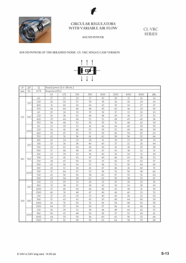
CIRCULAR REGULATORS WITH VARIABLE AIR FLOW CL-VRC
SERIESSOUND POWER
SOUND POWER OF THE IRRADIED NOISE: CL-VRC SINGLE CASE VERSION
64 58 55 6866
1500 47 61 58 59 631000 44 55 54 56 60 61 56 53
57 52 49 61560 40 47 48 50 561000
230 30 29 33 38 4857 56 51 46 61
44 42 5246
43 591500 44 57 54 541000 41 51 54 54 48
50 49 44 40 5432 45
560 37 43 43 4540
500
230 27 25 29 33
50 51
40 3646 40 33 5348 47 49
1000 37 46 44 46 43 38 31 5039 34 28 45560 33 38 37 38 42
200
200
230 23 19 23
441500 40 51
58 53 6726 20 3632 30
5926
60 57 55 51 64950 45 54 58 62 63700
53 50 48 60350 37 44 47 53 561000
100 26 32 34 41
54 5842 50
4656 52 50 44 60
41 40 5147
42 57950 42 50 54 57700 38 47 53 50 47
49 46 43 38 5331 44
350 34 41 43 4740
500
100 23 29 30 36
50 53
39 3443 38 32 5148 49 47
700 34 42 46 44 41 36 30 4837 32 26 44350 30 36 38 40 40
160
200
100 20 24 25
44950 37 46
56 52 6623 18 3531 29
5828
570 42 51 56 61 62
S VAV e CAV eng-vers 14.00.xls S-13

Ø �Pmm Pa
56 54 51 47 6052 50 47 43 56
2500 48 54 53 55
42 42 37 36 471500 43 48 46 50
47 44 38 55
500
400 32 35 32 37
45 42 36 523600 46 52 51 52 50
41 38 33 482500 43 49 47 49 481500 39 43 41 43 44
31 35 33 29 25 3964 59 54 69
315
200
400 28 30 27
61 57 52 672300 52 60 59 62 64
57 51 49 631600 49 58 58 61 62900 43 52 53 55 59
44 52 48 40 41 5457 56 53 47 62
1000
250 31 40 41
55 53 49 44 592300 49 57 56 58
52 49 44 41 561600 45 53 53 55
44 40 32 33 47900 40 48 47 50
46 43 36 53
500
250 28 36 36 38
43 40 34 502300 44 51 49 50 48
39 34 30 461600 41 48 46 47 46
30 22 22 37900 35 42 40 42 42
8000 dBa
250
200
250 23 30 29 30 35
m³/h frequency(Hz)63 125 250 500 1000 2000 4000
Q Sound power (Lw-db/ott.)
CIRCULAR REGULATORS WITH VARIABLE AIR FLOW CL-VRC
SERIESSOUND POWER
SOUND POWER OF THE IRRADIED NOISE: CL-VRC SINGLE CASE VERSION
64 61 60 7062 59 58 68
6300 58 63 61 63 66
58 54 54 644400 54 59 57 60 642500 47 54 51 54 59
42 49 50 44 45 5460 57 55 53 64
1000
700 31 42 38
57 55 53 50 626300 56 59 56 59
53 51 48 46 574400 52 55 53 55
43 44 38 37 482500 45 50 47 50
48 47 43 56
500
700 29 37 34 38
46 44 40 536300 53 53 51 53 52
44 42 37 524400 48 50 47 49 492500 41 47 40 47 49
32 35 35 30 27 4064 59 59 70
400
200
700 26 32 28
60 59 59 684800 55 61 62 64 65
58 54 54 633300 51 59 58 61 641800 46 53 52 55 58
43 49 48 44 46 5459 56 54 49 63
1000
500 34 40 37
57 58 49 49 634800 51 58 57 59
52 50 47 43 563300 48 58 52 58
43 45 36 37 491800 43 48 46 50
47 44 38 55
500
500 32 37 31 39
45 42 36 524800 46 52 51 52 50
40 40 35 513300 43 49 47 49 481800 39 46 41 46 48
30 36 34 31 26 4063 60 58 70
355
200
500 28 29 29
61 58 56 673600 54 62 61 63 66
57 53 52 632500 51 58 57 60 631500 46 52 51 54 59
42 49 49 43 45 5457 54 52 51 62
1000
400 35 39 363600 51 56 56 57
S VAV e CAV eng-vers 14.00.xls S-14

Ø �Pmm Pa
59 57 54 50 6355 53 50 46 59
10100 51 57 56 58
45 45 40 39 505600 46 51 49 53
50 47 41 58
500
1600 35 38 35 40
48 45 39 5514600 49 55 54 55 53
44 41 36 5110100 46 52 50 52 515600 42 46 44 46 47
34 38 36 32 28 4268 63 58 73
630
200
1600 31 33 30
65 61 56 717400 56 64 63 66 68
61 55 53 675200 53 62 62 65 662900 47 56 57 59 63
48 56 52 44 45 5861 60 57 51 66
1000
800 35 44 45
59 57 53 48 637400 53 61 60 62
56 53 48 45 605200 49 57 57 59
48 44 36 37 512900 44 52 51 54
50 47 40 57
500
800 32 40 40 42
47 44 38 547400 48 55 53 54 52
43 38 34 505200 45 52 50 51 50
34 26 26 412900 39 46 44 46 46
8000 dBa
500
200
800 27 34 33 34 39
m³/h frequency(Hz)63 125 250 500 1000 2000 4000
Q Sound power (Lw-db/ott.)
CIRCULAR REGULATORS WITH VARIABLE AIR FLOW CL-VRC
SERIESSOUND POWER
SOUND POWER OF THE IRRADIED NOISE: CL-VRC SINGLE CASE VERSION
66 63 61 7364 61 59 70
14600 57 65 64 66 69
60 56 55 6610100 54 61 60 63 665600 49 55 54 57 62
45 52 52 46 48 5760 57 55 54 65
1000
1600 38 42 3914600 54 59 59 60
S VAV e CAV eng-vers 14.00.xls S-15
Ø �Pmm Pa
41 37 544344 41 39 35 51
570 39 48 53 54 47400
37 34 31 46220 31 38 43 45 401000
60 20 26 30 34
49 5036 44
2940 36 33 27 48
25 24 3631
25 45570 35 45 49 48400 32 41 45 45 37 34 30
33 30 26220 27 35 39 392423 26 28
22 4015 3022 17
27 21 14 4012 3724 19
570 31 41 43 41 30400 28
2440 37 27
2021 15 9 32220 23 31 34 32
125
200
60 14 19 21
37
500
60 17
15 13
2000 4000 8000 dBa
6 0 21
63 125 250 500 1000
Q Sound power (Lw-db/ott.)m³/h frequency(Hz)
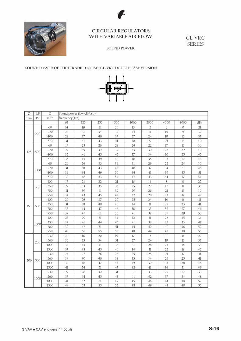
CIRCULAR REGULATORS WITH VARIABLE AIR FLOW CL-VRC
SERIESSOUND POWER
SOUND POWER OF THE IRRADIED NOISE: CL-VRC DOUBLE CASE VERSION
49 43 40 5552
1500 44 58 55 52 481000 41 52 51 49 45 46 41 38
42 37 34 48560 37 44 45 43 411000
230 27 26 30 31 3342 41 36 31 49
29 27 3831
28 461500 41 54 51 471000 38 48 39 39 33
35 34 29 25 4117 31
560 34 40 40 3825
500
230 24 22 26 26
47 44
25 2131 25 18 4245 40 34
1000 34 43 37 31 28 23 16 3824 19 13 33560 30 35 34 31 27
200
200
230 20 16 20
411500 37 48
43 38 5511 0 2217 15
4419
45 42 40 36 52950 42 51 55 55 48700
38 35 33 47350 34 41 44 46 411000
100 23 29 31 34
51 5139 47
3141 37 35 29 50
26 25 3732
27 46950 39 47 51 50700 35 44 38 35 32
34 31 28 23 4116 31
350 31 38 40 4025
500
100 20 26 27 29
47 46
24 1928 23 17 4245 42 32
700 31 39 39 29 26 21 15 3922 17 11 33350 27 33 35 33 25
160
200
100 17 21 22
41950 34 43
41 37 548 0 2216 14
4321
570 39 48 53 54 47
S VAV e CAV eng-vers 14.00.xls S-16
Ø �Pmm Pa
41 39 36 32 4937 35 32 28 44
2500 45 51 50 48
27 27 22 21 331500 40 45 43 43
32 29 23 45
500
400 29 32 29 30
30 27 21 423600 43 49 48 45 35
26 23 18 372500 40 46 44 42 331500 36 40 38 36 29
24 20 18 14 10 2649 44 39 56
315
200
400 25 27 24
46 42 37 552300 49 57 56 55 49
42 36 34 501600 46 55 55 54 47900 40 49 50 48 44
37 37 33 25 26 4142 41 38 32 51
1000
250 28 37 38
40 38 34 29 482300 46 54 53 51
37 34 29 26 441600 42 50 50 48
29 25 17 18 34900 37 45 44 43
31 28 21 43
500
250 25 33 33 31
28 25 19 402300 41 48 46 43 33
24 19 15 351600 38 45 43 40 31
15 7 7 25900 32 39 37 35 27
8000 dBa
250
200
250 20 27 26 23 20
m³/h frequency(Hz)63 125 250 500 1000 2000 4000
Q Sound power (Lw-db/ott.)
CIRCULAR REGULATORS WITH VARIABLE AIR FLOW CL-VRC
SERIESSOUND POWER
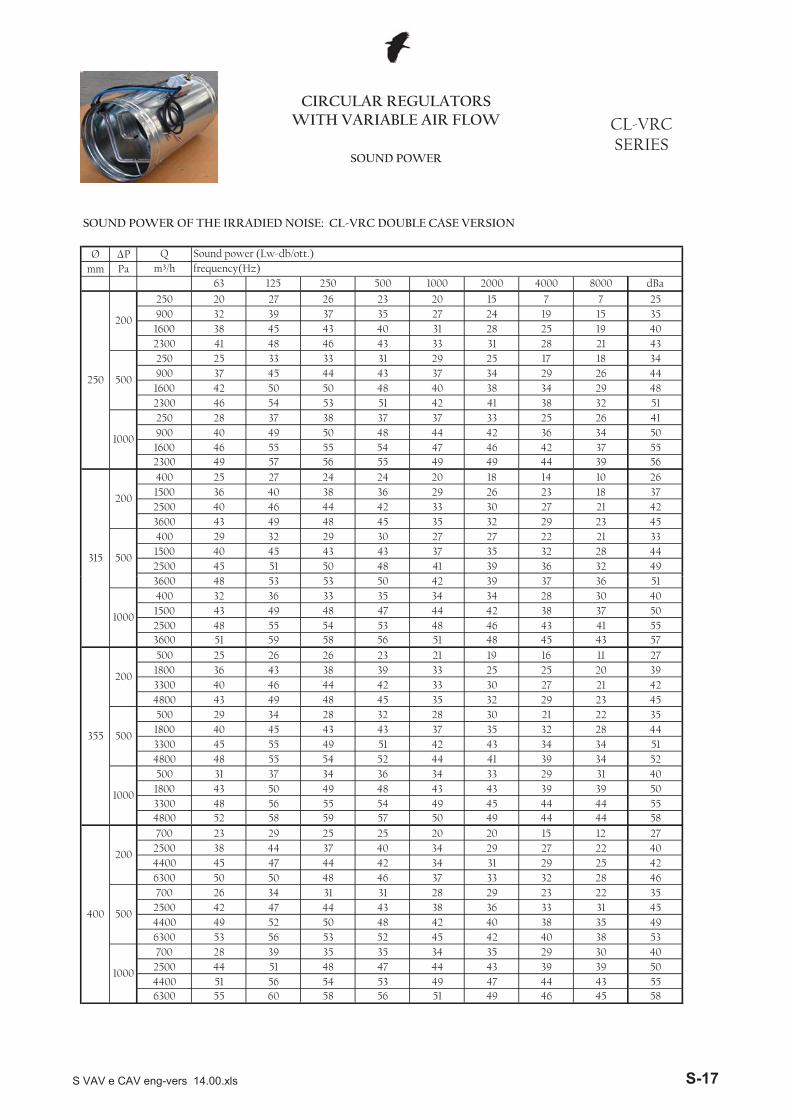
SOUND POWER OF THE IRRADIED NOISE: CL-VRC DOUBLE CASE VERSION
49 46 45 5847 44 43 55
6300 55 60 58 56 51
43 39 39 504400 51 56 54 53 492500 44 51 48 47 44
35 34 35 29 30 4045 42 40 38 53
1000
700 28 39 35
42 40 38 35 496300 53 56 53 52
38 36 33 31 454400 49 52 50 48
28 29 23 22 352500 42 47 44 43
33 32 28 46
500
700 26 34 31 31
31 29 25 426300 50 50 48 46 37
29 27 22 404400 45 47 44 42 342500 38 44 37 40 34
25 20 20 15 12 2749 44 44 58
400
200
700 23 29 25
45 44 44 554800 52 58 59 57 50
43 39 39 503300 48 56 55 54 491800 43 50 49 48 43
36 34 33 29 31 4044 41 39 34 52
1000
500 31 37 34
42 43 34 34 514800 48 55 54 52
37 35 32 28 443300 45 55 49 51
28 30 21 22 351800 40 45 43 43
32 29 23 45
500
500 29 34 28 32
30 27 21 424800 43 49 48 45 35
25 25 20 393300 40 46 44 42 331800 36 43 38 39 33
23 21 19 16 11 2748 45 43 57
355
200
500 25 26 26
46 43 41 553600 51 59 58 56 51
42 38 37 502500 48 55 54 53 481500 43 49 48 47 44
35 34 34 28 30 4042 39 37 36 51
1000
400 32 36 333600 48 53 53 50
S VAV e CAV eng-vers 14.00.xls S-17

Ø �Pmm Pa
44 42 39 35 5240 38 35 31 47
10100 48 54 53 51
30 30 25 24 365600 43 48 46 46
35 32 26 48
500
1600 32 35 32 33
33 30 24 4514600 46 52 51 48 38
29 26 21 4010100 43 49 47 45 365600 39 43 41 39 32
27 23 21 17 13 2953 48 43 60
630
200
1600 28 30 27
50 46 41 597400 53 61 60 59 53
46 40 38 545200 50 59 59 58 512900 44 53 54 52 48
41 41 37 29 30 4546 45 42 36 55
1000
800 32 41 42
44 42 38 33 527400 50 58 57 55
41 38 33 30 485200 46 54 54 52
33 29 21 22 382900 41 49 48 47
35 32 25 47
500
800 29 37 37 35
32 29 23 447400 45 52 50 47 37
28 23 19 395200 42 49 47 44 35
19 11 11 292900 36 43 41 39 31
8000 dBa
500
200
800 24 31 30 27 24
m³/h frequency(Hz)63 125 250 500 1000 2000 4000
Q Sound power (Lw-db/ott.)
CIRCULAR REGULATORS WITH VARIABLE AIR FLOW CL-VRC
SERIESSOUND POWER
SOUND POWER OF THE IRRADIED NOISE: CL-VRC DOUBLE CASE VERSION
51 48 46 6049 46 44 58
14600 54 62 61 59 54
45 41 40 5310100 51 58 57 56 515600 46 52 51 50 47
38 37 37 31 33 4345 42 40 39 54
1000
1600 35 39 3614600 51 56 56 53
S VAV e CAV eng-vers 14.00.xls S-18
Ø �Pmm Pa
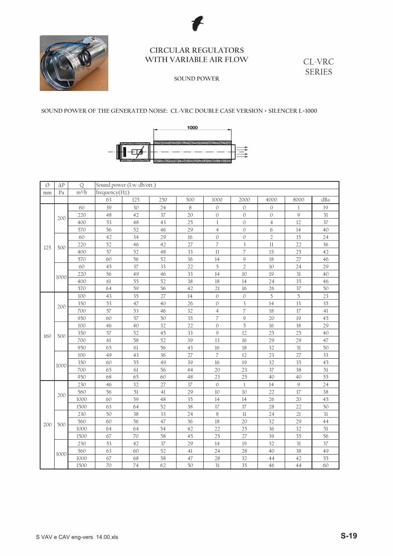
CIRCULAR REGULATORS WITH VARIABLE AIR FLOW CL-VRC
SERIESSOUND POWER
Q Sound power (Lw-db/ott.)m³/h frequency(Hz)
63 125 250 500 1000 2000 4000 8000 dBa
125
200
60 39 30 24 8 0 0 0 1 19220 48 42 37 20 0 0 0 9 31400 53 48 43 25 1 0 4 12 37570 56 52 46 29 4 0 6 14 40
500
60 42 34 29 16 0 0 2 15 24220 52 46 42 27 7 3 11 22 36400 57 52 48 33 11 7 15 25 42570 60 56 52 36 14 9 18 27 46
1000
60 45 37 33 22 5 2 10 24 29220 56 49 46 33 14 10 19 31 40400 61 55 52 38 18 14 24 35 46570 64 59 56 42 21 16 26 37 50
SOUND POWER OF THE GENERATED NOISE: CL-VRC DOUBLE CASE VERSION + SILENCER L=1000
570 64 59 56 42 21 16 26 37 50
160
200
100 43 35 27 14 0 0 5 5 23350 53 47 40 26 0 3 14 13 35700 57 53 46 32 4 7 18 17 41950 60 57 50 35 7 9 20 19 45
500
100 46 40 32 22 0 5 16 18 29350 57 52 45 33 9 12 25 25 40700 61 58 52 39 13 16 29 29 47950 65 61 56 43 16 18 32 31 50
1000
100 49 43 36 27 7 12 23 27 33350 60 55 49 39 16 19 32 35 45700 65 61 56 44 20 23 37 38 51950 68 65 60 48 23 25 40 40 55
200
200
230 46 32 27 17 0 1 14 9 24560 56 51 41 29 10 10 22 17 381000 60 59 48 35 14 14 26 20 451500 63 64 52 38 17 17 28 22 50
500
230 50 38 33 24 8 11 24 21 31560 60 56 47 36 18 20 32 29 441000 64 64 54 42 36 32 511500 67 70 58 45
2239
63 60 52 41
2525 27
1935 56
1000
230 53 42 3738 4928
32 31 37
47 2824
29 1440560
1500 70 74 62 501000 67 68 58
31 35 46 44 6032 44 42 55
S VAV e CAV eng-vers 14.00.xls S-19

Ø �Pmm Pa
CIRCULAR REGULATORS WITH VARIABLE AIR FLOW CL-VRC
SERIESSOUND POWER
Q Sound power (Lw-db/ott.)
SOUND POWER OF THE GENERATED NOISE: CL-VRC DOUBLE CASE VERSION + SILENCER L=1000
m³/h frequency(Hz)63 125 250 500 1000 2000 4000 8000 dBa
250
200
250 46 43 35 23 6 16 18 19 31900 58 55 46 35 13 25 30 27 431600 64 61 52 40 17 29 36 31 482300 67 64 55 43 19 32 39 33 51
500
250 51 49 42 31 15 26 28 30 39900 63 61 53 43 23 35 40 38 501600 68 66 59 48 26 39 45 41 552300 72 70 62 51 28 42 49 44 58
1000
250 54 53 47 37 23 34 36 38 45900 66 65 59 48 30 43 47 46 551600 72 71 64 54 33 47 53 49 612300 75 73 65 55 35 50 55 51 63
315
200
400 51 43 35 26 19 23 27 25 341500 62 56 49 38 28 31 36 33 462500 66 62 55 44 32 35 40 36 513600 69 65 59 47 34 37 42 38 54
500
400 55 48 40 32 26 32 35 36 411500 66 61 54 45 36 40 45 43 522500 71 67 61 50 40 44 49 47 573600 74 69 64 52 41 44 50 51 603600 74 69 64 52 41 44 50 51 60
1000
400 58 52 44 37 33 39 41 45 481500 69 65 59 49 43 47 51 52 582500 74 71 65 55 47 51 56 56 633600 77 75 69 58 50 53 58 58 66
355
200
500 51 43 38 28 21 29 31 27 371800 62 60 50 44 33 35 40 36 493300 66 63 56 47 33 40 42 37 524800 69 66 60 50 35 42 44 39 56
500
500 55 51 40 37 28 40 36 38 451800 66 62 55 48 37 45 47 44 543300 71 72 61 56 42 53 49 50 614800 74 72 66 57 44 51 54 50 63
1000
500 57 54 46 41 34 43 44 47 511800 69 67 61 53 43 53 54 55 613300 74 73 67 59 49 55 59 60 664800 78 75 71 62 50 59 59 60 68
400
200
700 49 46 39 33 22 33 31 28 392500 64 61 51 48 36 42 43 38 514400 71 64 58 50 36 44 45 41 556300 76 67 62 54 39 46 48 44 59
500
700 52 51 45 39 30 42 39 38 472500 68 64 58 51 40 49 49 47 574400 75 69 64 56 53 54 51 626300 79 73 67 60
1000
700 54 56 49
44
68 62 55 4651
48 45 46 5347 55 56 54 65
72
43 3655 62
4400 77 73 68 6164 53
60 60 592500 70
6300 81 77 62 62 61 70
5567
56
S VAV e CAV eng-vers 14.00.xls S-20

Ø �Pmm Pa
CIRCULAR REGULATORS WITH VARIABLE AIR FLOW CL-VRC
SERIESSOUND POWER
Q Sound power (Lw-db/ott.)
SOUND POWER OF THE GENERATED NOISE: CL-VRC DOUBLE CASE VERSION + SILENCER L=1000
m³/h frequency(Hz)63 125 250 500 1000 2000 4000 8000 dBa
500
200
800 50 48 46 39 36 36 29 29 432900 62 60 57 51 43 45 41 37 545200 68 66 63 56 47 49 47 41 597400 71 69 66 59 49 52 50 43 62
500
800 55 54 53 47 45 46 39 40 522900 67 66 64 59 53 55 51 48 625200 72 71 70 64 56 59 56 51 677400 76 75 73 67 58 62 60 54 70
1000
800 58 58 58 53 53 54 47 48 592900 70 70 70 64 60 63 58 56 695200 76 76 75 70 63 67 64 59 747400 79 78 76 71 65 70 66 61 76
630
200
1600 54 47 43 41 38 39 36 31 455600 65 60 57 53 47 47 45 39 5610100 69 66 63 59 51 51 49 42 6114600 72 69 67 62 53 53 51 44 64
500
1600 58 52 48 47 45 48 44 42 535600 69 65 62 60 55 56 54 49 6310100 74 71 69 65 59 60 58 53 6814600 77 73 72 67 60 60 59 57 69
1000
1600 61 56 52 52 52 55 50 51 605600 72 69 67 64 62 63 60 58 6910100 77 75 73 70 6614600 80 79 77 73 69
6767 64 7765 62 74
69
S VAV e CAV eng-vers 14.00.xls S-21

Ø �Pmm Pa
41 5433 39
570 65 59 60 50 37 32 35
30 26 28400 62 55 56 46 34 30
28 3335 44
50220 57 49 50 41
49
1000
60 46 37 37 30 21 18 19
23 24570 61 56 56 44 30 25 27400 58 52 52 41 27 29 45
31
220 53 46 46 35 23 1914 11 11 19 28
4020 26
16 15 18 43
500
60 43 34 33 24
13 13 16 40570 57 52 50 37 20400 54 48 47 33 17
2 0 5 2228 14 10 9 13 34220 49 42 4116 5
2000 4000 8000 dBa
125
200
60 40 30 28
63 125 250 500 1000
Q Sound power (Lw-db/ott.)m³/h frequency(Hz)
SOUND POWER OF THE GENERATED NOISE: CL-VRC DOUBLE CASE VERSION + SILENCER L=500
CIRCULAR REGULATORS WITH VARIABLE AIR FLOW CL-VRC
SERIESSOUND POWER
6258
1500 70 74 63 57 44 47 53 4968 59 54 41 44 51 47
27 31 39560 63 60 53 48 37
36 4347 43 53
39 46 40 57
401000
230 53 42 38 36
1000 67
37 43 37 531500 67 70 59 52 381000 64 64 55 49 35
43 31 32 39 34 4721 23 31 26 36
14
29 35 27 51
500
230 50 38 34 31560 60 56 48
26 33 25 46
2822 29 22 40
1500 63 64 53 45 301000 60 59 49 42 27560 56 51 42 36
1328 2423
38 48 47 5913 21
200
200
230 46 32
521000
100 49 44
37 36 45 45950 68 66 63 56 40
55350 60 56 52 47 33 32 40 42
24 25 31 34 3949
39 35
700 65 62 59
29 37 36950 65 62 59 51 33 31700 61 59 55 47 30
24 25 33
5038 54
33 32 44
40
350 57 53 4817 18
41 26 25
22 28 26 48
500
100 46 41 35 30
20 26 24 44950 60 58 53 43 24
16 22 20 38700 57 54 49 40 21
8 13 12 26350 53 48 43 34 17
41 54
160
200
100 43 36 30 22 8570 65 59 60 50 37 32 35
S VAV e CAV eng-vers 14.00.xls S-22

Ø �Pmm Pa
53 54 493600 74 70 65 58 53 532500 71 68 62 56 52
40 38 47
6153 63
50 45 57
55
1500 66 62 5538 41
51 48 49
46 47 40 57
500
400 55 49 41 38
44 45 38 543600 69 66 60 53 46
40 41 35 492500 66 63 56 50 44
32 32 27 391500 62 57 50 44 40
54 67
315
200
400 51 44 36 32 31
59 522300 75 74 66 61 49 61 61
44 54 531600 72 72 65 60 47 58
41 5049 60
65900 66 66 60 54
62
1000
250 54 54 48 43 37 45 42
50 512300 72 71 63 57 42 53 551600 68 67 60 54 40 44 59
47
900 63 62 54 49 37 4629 37 34 33 43
5446 41
43 45 36 54
500
250 51 50 43 37
40 42 34 512300 67 65 56 49 331600 64 62 53 46 31
22 3541 27 36 36 30 4656 4729 20 27 24
8000 dBa
250
200
250 46 44 36900 58
m³/h frequency(Hz)63 125 250 500 1000 2000 4000
CIRCULAR REGULATORS WITH VARIABLE AIR FLOW CL-VRC
SERIESSOUND POWER
Q Sound power (Lw-db/ott.)
SOUND POWER OF THE GENERATED NOISE: CL-VRC DOUBLE CASE VERSION + SILENCER L=500
7472
6300 81 77 72 70 6573
6564 6368 67 63
62
68 66
684400 77
4962 61 58
66
50 5859 59 672500 70
58 69
1000
700 54 56 49 49 48 54
58 556300 79 73 67 66 59 61 60
75 69 64 62 56 59 662500 68 64 58 57 52 55 534400
48 43 42 5251 61
52 48 62
500
700 52 51 45 45 42
50 49 456300 76 67 62 60 51 52
48 48 47 424400 71 64 58 56 48
35 32 445658
2500 64 61 51 54
73
400
200
700 49 46 39 39 34 39
704800 78 75 71 69 63 66 64 62
73 67 66 62 62 64 621800 69 67 61 60 56 603300 74
47 50 49 49 5659 57 66
58 59 52 67
1000
500 57 54 46 48
60 54 52 664800 74 72 66 64 573300 71 72 61 63 55
55 50 52 52 46 5941 47 41 40 51
29
49 49 41 59
500
500 55 51 40 441800 66 62 55
47 47 39 56
4242 45 38 53
4800 69 66 60 57 483300 66 63 56 54 461800 62 60 50 51
3438 3546
62 63 60 7036 36
355
200
500 51 43
611000
400 58 53
59 60 61 583600 77 76 70 64 62
681500 69 66 60 55 55 56 56 54
45 48 46 47 5463
45 43
2500 74 72 66
3600 74 70 65 58 53 53 53 6355
S VAV e CAV eng-vers 14.00.xls S-23
Ø �Pmm Pa
61 56 7161 62 60
10100 74 72 69 66 66 64
52 52 47 45 5757 52 67
500
1600 58 53 48 485600 69 66 62
52 4514600 72 70 67 63 60 57 54
48 42 5910100 69 67 63 60 58 55 63
47 66
5600 65 61 57 54 54 5142 45 43 39 34 49
75 70 64 80
630
200
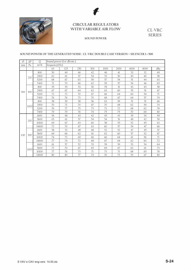
1600 54 48 43
72 68 62 787400 79 79 76 74 755200 76 77 75 73 732900 70 71 70 67 70
63 59 51 51 6659 7468 62
67 64 57 74
1000
800 58 59 58 56
60 5463
717400 76 76 73 70 68
5560
5200 72 72 70 67 66 642900
5855 51 67
57 5451 43 43
500
800 55 55 53 5067 64 6267
7400 71 70 66 62 59
585200 68 67 63 59 57 54 51 442900 62 61 57 54 53
41 33 32 49
6346 65
50 45 40
8000 dBa
500
200
800 50 49 46 42 46
m³/h frequency(Hz)63 125 250 500 1000 2000 4000
CIRCULAR REGULATORS WITH VARIABLE AIR FLOW CL-VRC
SERIESSOUND POWER
Q Sound power (Lw-db/ott.)
SOUND POWER OF THE GENERATED NOISE: CL-VRC DOUBLE CASE VERSION + SILENCER L=500
73 70 67 8071 68 65 78
14600 80 80 77 74 7610100 77 76 73 71 735600 72 70 67 65 69
59 53 54 6461 7367 63
62 60 72
1000
1600 61 57 52 53 5914600 77 74 72 68 67 64
S VAV e CAV eng-vers 14.00.xls S-24
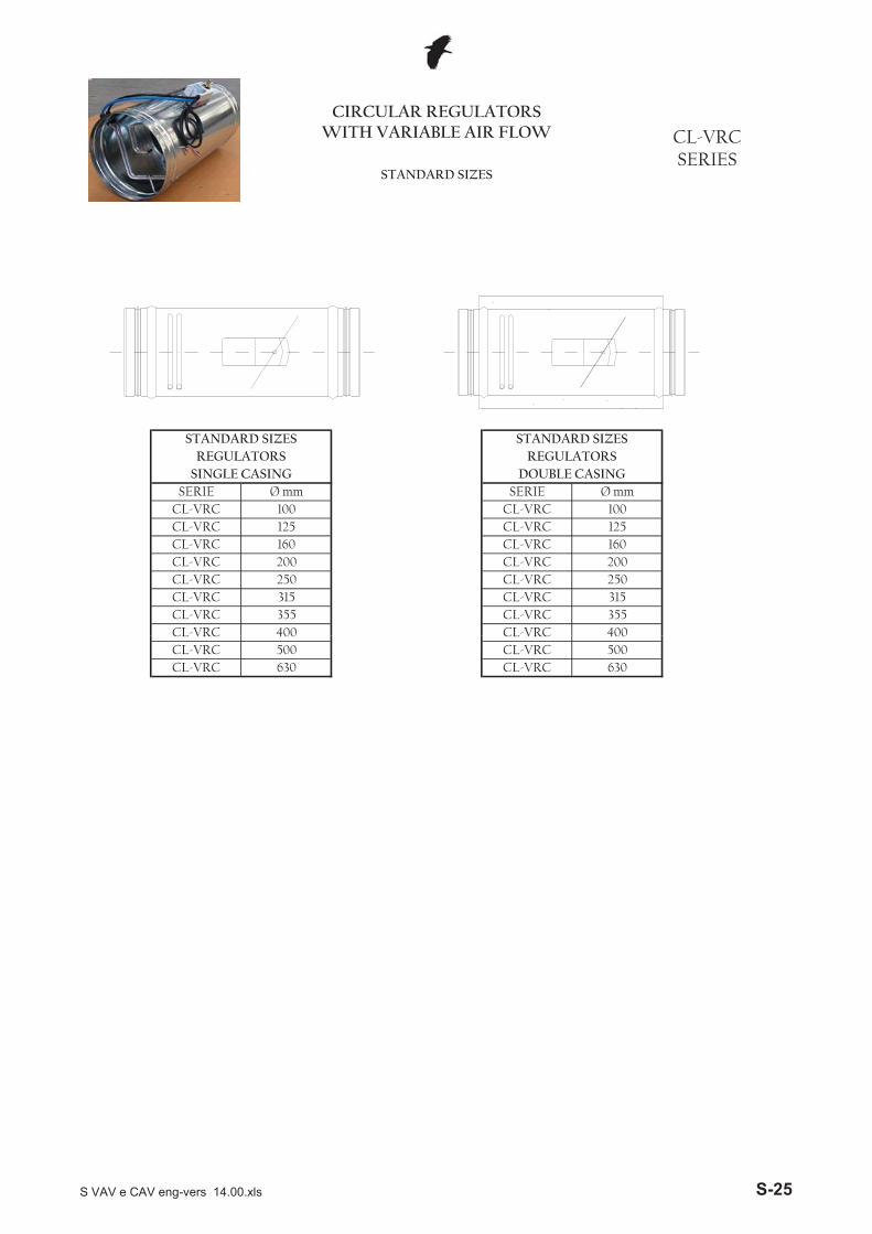
SERIE Ø mm SERIE Ø mm
CIRCULAR REGULATORS WITH VARIABLE AIR FLOW CL-VRC
SERIESSTANDARD SIZES
STANDARD SIZES
SINGLE CASING
CL-VRC 100 CL-VRC 100CL-VRC 125 CL-VRC 125CL-VRC 160 CL-VRC 160CL-VRC 200 CL-VRC 200CL-VRC 250 CL-VRC 250CL-VRC 315 CL-VRC 315CL-VRC 355 CL-VRC 355CL-VRC 400
REGULATORSSTANDARD SIZES
REGULATORSDOUBLE CASING
CL-VRC 400
CL-VRC 630 CL-VRC 630
CL VRC 400CL-VRC 500 CL-VRC 500
CL VRC 400
S VAV e CAV eng-vers 14.00.xls S-25
M SuppyR Extraction
DS
NI
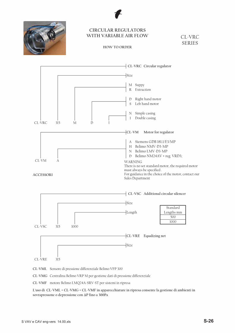
AHND
Belimo NMV-D3-MPBelimo LMV-D3-MPBelimo NM24AV + reg. VRD3;
CL-VM A
CL-VM Motor for regulator
Siemens GDB 181.1/E3/MP
Left hand motor
Simple casingDouble casing
CL-VRC 315 M D I
Size
Right hand motor
CL-VRC SERIES
HOW TO ORDER
CIRCULAR REGULATORS WITH VARIABLE AIR FLOW
CL-VRC Circular regulator
WARNINGThere is no set standard motor, the required motor must always be specified .
L'uso di CL-VML + CL-VMG + CL-VMF in apparecchiature in ripresa consente la gestione di ambienti insovrapressone o depressione con �P fino a 300Pa
Size
CL-VML Sensore di pressione differenziale Belimo VFP 300
CL-VMG Centralina Belimo VRP M per gestione dati di pressione differenziale
CL-VMF motore Belimo LMQ24A-SRV-ST per sistemi in ripresa
CL-VRE
CL-VRE Equalizing net
Size
CL-VSC Additional circular silencer
315
StandardLength Lengths mm
5001000
CL-VSC 315 1000
ACCESSORIy p
For guidance in the choice of the motor, contact our Sales Department
S VAV e CAV eng-vers 14.00.xls S-26
CL-VCC CL-VCL SERIES
VARIABLE AIR FLOW UNITS
OVERVIEW
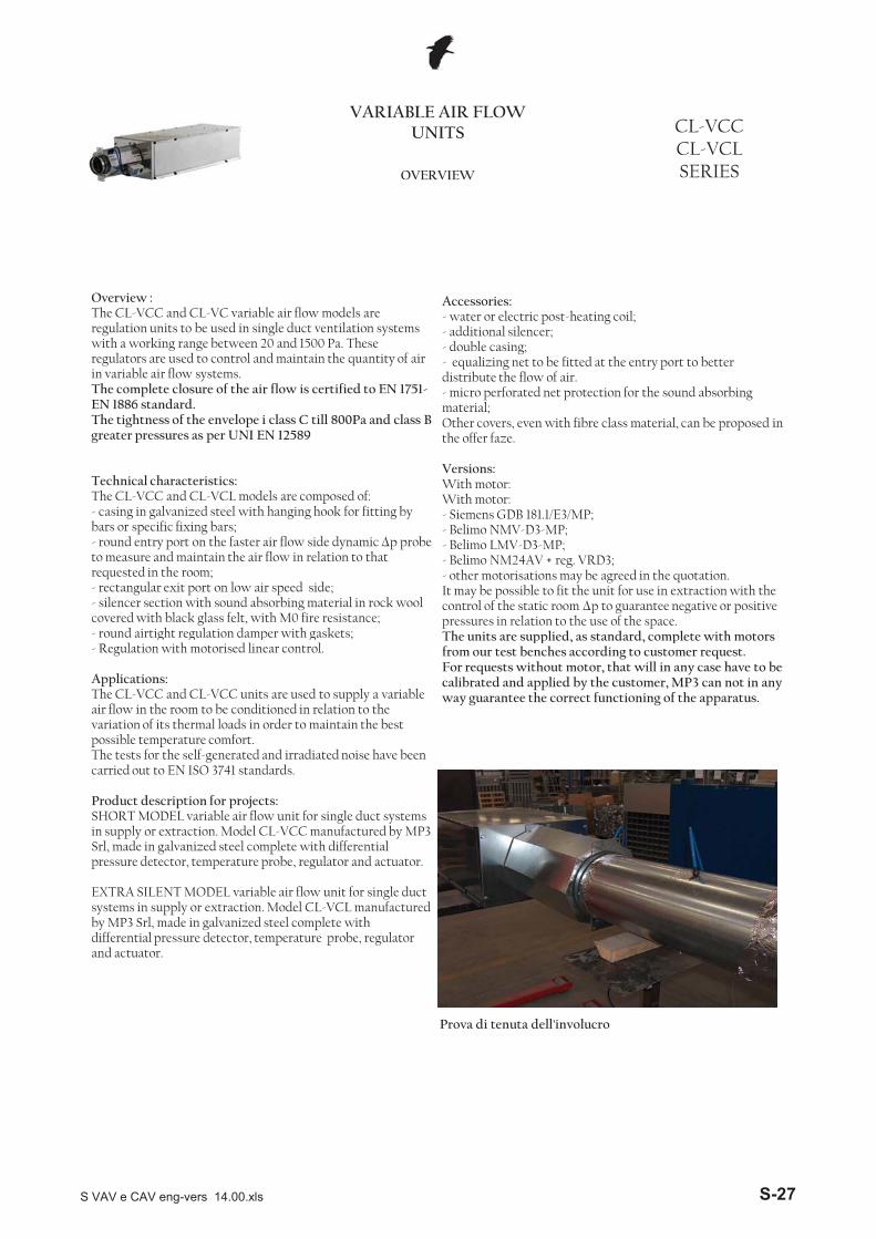
Overview :The CL-VCC and CL-VC variable air flow models are regulation units to be used in single duct ventilation systems with a working range between 20 and 1500 Pa. These regulators are used to control and maintain the quantity of air in variable air flow systems.The complete closure of the air flow is certified to EN 1751-EN 1886 standard.The tightness of the envelope i class C till 800Pa and class B greater pressures as per UNI EN 12589
Technical characteristics: The CL-VCC and CL-VCL models are composed of:- casing in galvanized steel with hanging hook for fitting by bars or specific fixing bars;- round entry port on the faster air flow side dynamic �p probe to measure and maintain the air flow in relation to that requested in the room;- rectangular exit port on low air speed side;- silencer section with sound absorbing material in rock wool covered with black glass felt, with M0 fire resistance;- round airtight regulation damper with gaskets;
Accessories:- water or electric post-heating coil;- additional silencer;- double casing;- equalizing net to be fitted at the entry port to better distribute the flow of air.- micro perforated net protection for the sound absorbing material;Other covers, even with fibre class material, can be proposed in the offer faze.
Versions:With motor:With motor:- Siemens GDB 181.1/E3/MP;- Belimo NMV-D3-MP; - Belimo LMV-D3-MP; - Belimo NM24AV + reg. VRD3; - other motorisations may be agreed in the quotation.It may be possible to fit the unit for use in extraction with the control of the static room �p to guarantee negative or positive pressures in relation to the use of the space. The units are supplied as standard complete with motors
Prova di tenuta dell'involucro
g g p g ;- Regulation with motorised linear control.
Applications:The CL-VCC and CL-VCC units are used to supply a variable air flow in the room to be conditioned in relation to the variation of its thermal loads in order to maintain the best possible temperature comfort. The tests for the self-generated and irradiated noise have been carried out to EN ISO 3741 standards.
Product description for projects:SHORT MODEL variable air flow unit for single duct systems in supply or extraction. Model CL-VCC manufactured by MP3 Srl, made in galvanized steel complete with differential pressure detector, temperature probe, regulator and actuator.
EXTRA SILENT MODEL variable air flow unit for single duct systems in supply or extraction. Model CL-VCL manufactured by MP3 Srl, made in galvanized steel complete with differential pressure detector, temperature probe, regulator and actuator.
The units are supplied, as standard, complete with motors from our test benches according to customer request. For requests without motor, that will in any case have to be calibrated and applied by the customer, MP3 can not in any way guarantee the correct functioning of the apparatus.
S VAV e CAV eng-vers 14.00.xls S-27
CL-VCC CL-VCL SERIESWORKING PRINCIPLES
VARIABLE AIR FLOW UNITS
WORKING PRINCIPLE “INDEPENDENT PRESSURE”
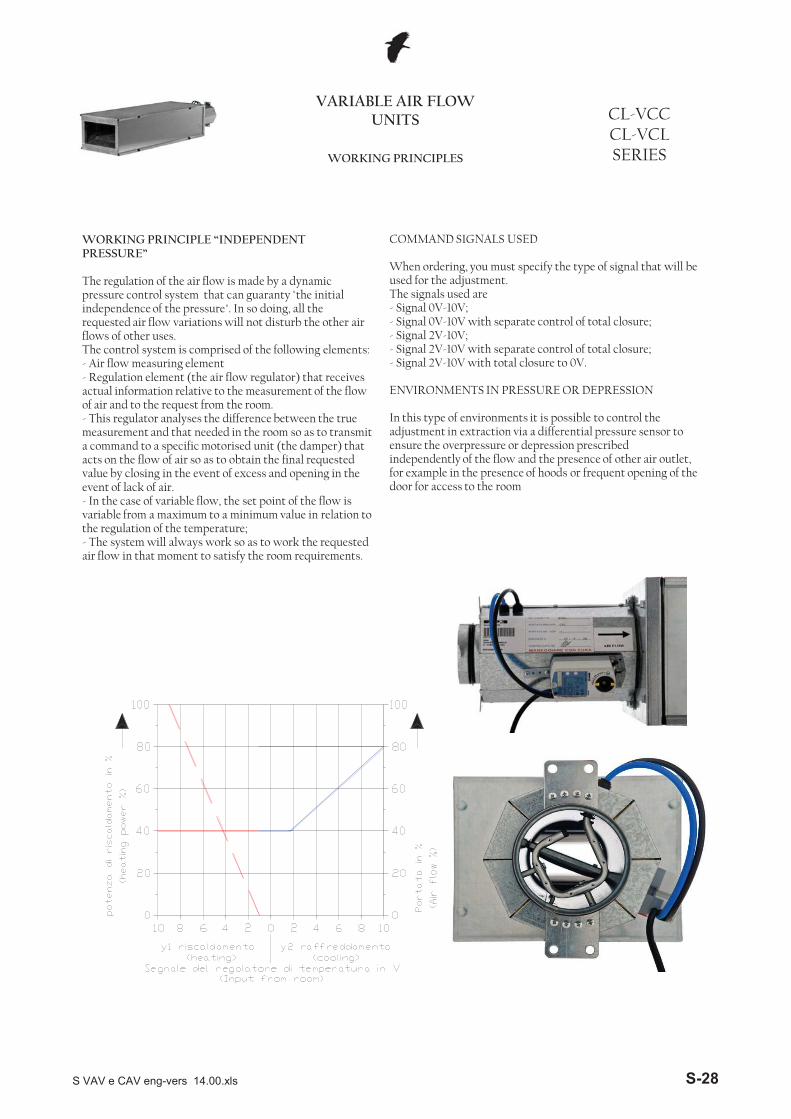
The regulation of the air flow is made by a dynamic pressure control system that can guaranty "the initial independence of the pressure". In so doing, all the requested air flow variations will not disturb the other air flows of other uses.The control system is comprised of the following elements:- Air flow measuring element - Regulation element (the air flow regulator) that receives actual information relative to the measurement of the flow of air and to the request from the room.- This regulator analyses the difference between the true measurement and that needed in the room so as to transmit a command to a specific motorised unit (the damper) that acts on the flow of air so as to obtain the final requested value by closing in the event of excess and opening in the event of lack of air.- In the case of variable flow, the set point of the flow is variable from a maximum to a minimum value in relation to the regulation of the temperature;- The system will always work so as to work the requested air flow in that moment to satisfy the room requirements.
COMMAND SIGNALS USED
When ordering, you must specify the type of signal that will be used for the adjustment.The signals used are- Signal 0V-10V;- Signal 0V-10V with separate control of total closure;- Signal 2V-10V;- Signal 2V-10V with separate control of total closure;- Signal 2V-10V with total closure to 0V.
ENVIRONMENTS IN PRESSURE OR DEPRESSION
In this type of environments it is possible to control the adjustment in extraction via a differential pressure sensor to ensure the overpressure or depression prescribed independently of the flow and the presence of other air outlet, for example in the presence of hoods or frequent opening of the door for access to the room
S VAV e CAV eng-vers 14.00.xls S-28
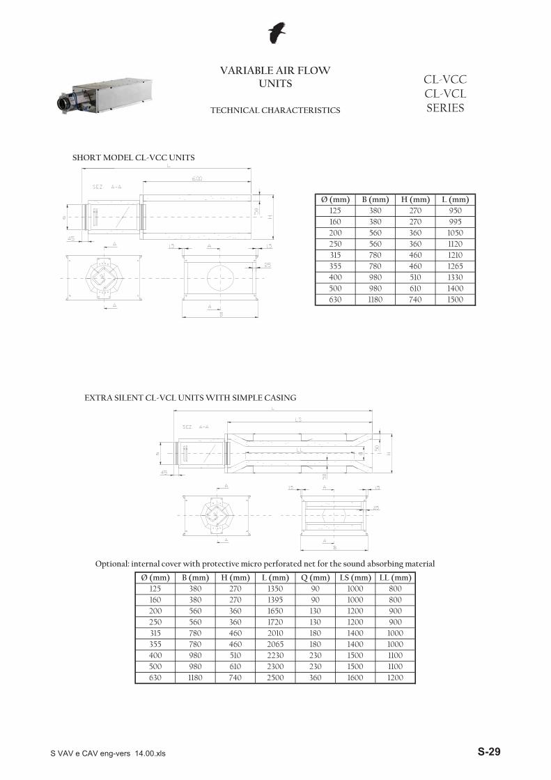
500 980 610 1400630 1180 740 1500
250
355
380 270
CL-VCC CL-VCL SERIESTECHNICAL CHARACTERISTICS
VARIABLE AIR FLOW UNITS
125 380 270 950Ø (mm) B (mm) H (mm)
160 995
L (mm)
200 560 360 10501120560 360
980 1330
12101265460780
510400
315 780 460
SHORT MODEL CL-VCC UNITS
EXTRA SILENT CL-VCL UNITS WITH SIMPLE CASING
1100630 1180 740 2500 360 1600 1200500 980 610 2300 230 1500
20652230
270360
Ø (mm) Q (mm)B (mm) H (mm) L (mm)270
780980
125
355
160200250315
180
130130180
400
380380560560780
510
13501395165017202010
360460460
230
1000100012001200140014001500
9090
1100
800
9009001000
800
1000
LL (mm)LS (mm)
Optional: internal cover with protective micro perforated net for the sound absorbing material
S VAV e CAV eng-vers 14.00.xls S-29
CL-VCC CL-VCL SERIESTECHNICAL CHARACTERISTICS
VARIABLE AIR FLOW UNITS
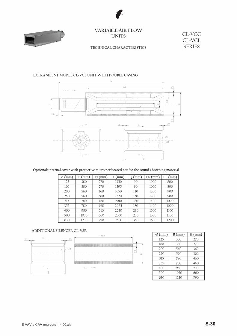
EXTRA SILENT MODEL CL-VCL UNIT WITH DOUBLE CASING
Optional: internal cover with protective micro perforated net for the sound absorbing material
1230 790 2500
500 1030 660
355
200
780
125
790
360 1600 1200
510
250
Ø (mm) B (mm)
360460
660 2300 230 1500
630 1230
160380380
1100
460
360270
400
560560780
980
315
1200
355780 460
120014001400
H (mm)270
11001000
630
15002230780
500 1030400
125160
510980460
315250200
560 9001720
1802065180130
10002010
230
H (mm) L (mm)
380360
Q (mm)90
560270270 1350
3601650
LS (mm)
900
1000LL (mm)Ø (mm)
800
1308001395
38090 1000
B (mm)
ADDITIONAL SILENCER CL-VSR
S VAV e CAV eng-vers 14.00.xls S-30
243300
391521
187218792299
SERIECL-VCCCL-VCL
PERFORMANCE
CASSETTEA PORTATA VARIABILE
Air speedm/s
Diameter Air flowm³/hmm
Pressure lossPa
6,8
5,87,1
7,5
8,8
8,310,9
380
11661431
5,76,9
9,4
9,05,6
11,1
6,88,4
20
3056
658622757
2030
50200
250
315
1959249330
2050
961
355
20
125
160 3050
30
50
2030
8,2
324122613662
203050
5,67,19,3
400
502030
5,1
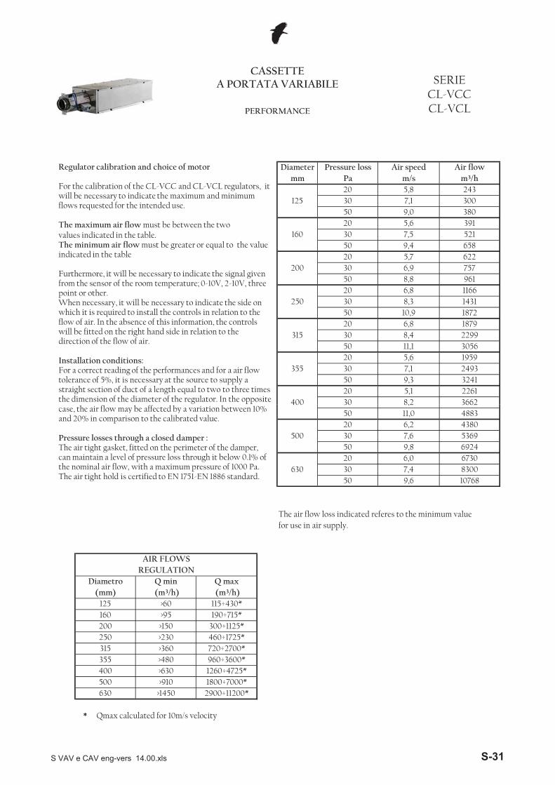
Regulator calibration and choice of motor
For the calibration of the CL-VCC and CL-VCL regulators, it will be necessary to indicate the maximum and minimum flows requested for the intended use.
The maximum air flow must be between the two values indicated in the table.The minimum air flow must be greater or equal to the value indicated in the table
Furthermore, it will be necessary to indicate the signal given from the sensor of the room temperature; 0-10V, 2-10V, three point or other.When necessary, it will be necessary to indicate the side on which it is required to install the controls in relation to the flow of air. In the absence of this information, the controls will be fitted on the right hand side in relation to the direction of the flow of air.
Installation conditions:For a correct reading of the performances and for a air flow tolerance of 5%, it is necessary at the source to supply a straight section of duct of a length equal to two to three times the dimension of the diameter of the regulator. In the opposite
*
20 6,2
9,8 692420 6,0
500 30 7,6 536950
50 9,6 10768630 30
67307,4 8300
4380
8,2 3662
The air flow loss indicated referes to the minimum value
400
for use in air supply.
488311,05030
(mm) (m³/h) (m³/h)
AIR FLOWSREGULATION
Diametro Q min Q max
160 >95 190÷715*125 >60 115÷430*
250 >230 460÷1725*200 >150 300÷1125*
355 >480 960÷3600*315 >360 720÷2700*
Qmax calculated for 10m/s velocity
400 >630 1260÷4725*1800÷7000*2900÷11200*
500 >910630 >1450
case, the air flow may be affected by a variation between 10% and 20% in comparison to the calibrated value.
Pressure losses through a closed damper :The air tight gasket, fitted on the perimeter of the damper, can maintain a level of pressure loss through it below 0.1% of the nominal air flow, with a maximum pressure of 1000 Pa.The air tight hold is certified to EN 1751-EN 1886 standard.
S VAV e CAV eng-vers 14.00.xls S-31
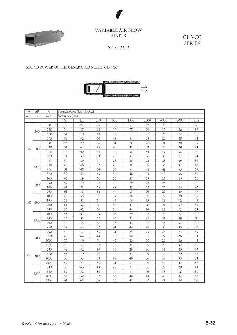
Ø �Pmm Pa
VARIABLE AIR FLOW UNITS
Q Sound power (Lw-db/ott.)
NOISE DATA
CL-VCCSERIES
m³/h frequency(Hz)63 125 250 500 1000 2000 4000 8000 dBa
125
200
60 48 24 26 23 21 22 25 21 31220 50 37 44 36 27 26 19 26 39400 51 40 40 42 31 27 23 27 41570 53 42 50 43 31 28 25 28 44
500
60 45 29 36 31 26 26 21 28 35220 51 42 45 42 35 32 25 29 43400 50 60 52 50 38 34 39 32 51570 54 58 59 48 41 36 37 31 53
1000
60 34 29 31 28 26 25 28 29 34220 46 46 52 46 38 35 33 32 47400 51 65 56 55 41 42 41 36 55570 52 63 63 54 46 44 40 36 57
SOUND POWER OF THE GENERATED NOISE: CL-VCC
570 52 63 63 54 46 44 40 36 57
160
200
100 42 29 32 26 23 23 23 26 32350 52 42 46 38 29 25 26 21 40700 61 51 53 44 35 29 27 26 47950 61 52 52 44 35 36 29 29 47
500
100 46 36 37 29 26 29 29 28 36350 56 51 53 47 38 35 31 32 48700 61 57 61 53 43 36 31 32 55950 62 62 60 54 44 36 36 32 55
1000
100 56 41 43 37 29 32 28 27 40350 56 53 57 46 36 41 33 29 51700 59 56 61 58 45 42 36 32 57950 59 63 62 61 44 41 37 35 60
200
200
230 36 32 33 31 24 23 26 23 33560 45 44 44 35 26 25 29 26 391000 55 49 51 42 30 29 29 26 451500 56 51 52 42 33 35 28 32 46
500
230 48 42 39 36 29 26 32 26 39560 55 49 54 44 33 35 32 29 481000 53 55 59 49 40 36 39 35 531500 59 61 63 51 41 39 44 47 57
1000
230 53 45 48 40 33 31 25 29 43560 52 52 56 47 41 36 36 36 501000 56 59 62 55 461500 61 65 66 59 45 49 43 44 61
44 43 37 57
S VAV e CAV eng-vers 14.00.xls S-32

Ø �Pmm Pa
250
200
250 43 36 36900 50 48 46
33 26 29 29 28 3744 32 33 30 27 44
1600 51 49 47 42 39 35 30 28 452300 55 50 46 42 37 43 36 28 47
500
250 46 39 41 36 28 34 31 32 40900 56 57 55 52 44 42 34 35 531600 62 62 61 55 46 45 38 35 572300 60 63 59 56 47 49 44 35 57
1000
250 57 45 45 39 36 35 37 36 44900 60 57 63 52 47 45 39 42 571600 64 66 71 62 542300 66 69 70 65 56 53 51 51 66
46 45 46 65
CL-VCCSERIES
NOISE DATA
VARIABLE AIR FLOW UNITS
Q Sound power (Lw-db/ott.)m³/h frequency(Hz)
63 125 250 2000 4000 8000 dBa500 1000
315
200
400 51 39 361500 62 51 46
25 4138 35
36 36 34 2942 39 25 46
2500 61 53 46 42 42 37 33 26 473600 59 49 45 45 38 39 36 29 47
500
400 55 44 46 39 42 37 44 38 481500 64 56 51 52 48 47 45 37 552500 72 63 61 55 51 48 46 39 58
SOUND POWER OF THE GENERATED NOISE: CL-VCC
51 52 50 6346 54 53 65
6300 77 71 66 61 52
41 53 52 604400 78 74 69 62 522500 69 71 61 52 47
38 38 39 42 40 4849 43 45 44 61
1000
700 65 53 46
48 40 42 40 586300 73 68 61 61
43 36 38 41 544400 74 68 61 53
35 32 31 31 452500 70 66 53 52
39 42 36 54
500
700 56 49 46 45
36 35 33 496300 70 59 50 52 494400 66 54 48 48 41
36 32 31 28 29 4332 26 25 29 29 36
400
200
700 46 37 332500 62 53 46
3600 75 66 59 57 51 51 48 39 60
1000
400 70 52 44 44 56 46 42 44 5754 53 49 631500 67 65 63 56 58
2500 73 64 71 61 61 57 53 50 673600 79 65 70 63 60
355
200
500 48 39 331800 59 49 44
28 3858 52 52 67
33 3137 28 32 2642 32 31 43
3300 63 53 52 45 40 39 37 33 494800 71 64 58 57 49 46 39 41 58
500
500 56 46 41 39 36 28 27 35 421800 65 61 55 51 44 36 35 36 533300 75 69 61 58 44 47 41 43 594800 78 72 65 57 45 49 42 43 61
1000
500 63 49 47 38 36 37 36 40 4648 45 42 611800 67 67 66 58 51
3300 74 75 71 62 554800 80 72 70 60 54 54 54 45 65
54 51 46 66
S VAV e CAV eng-vers 14.00.xls S-33

Ø �Pmm Pa
54 51 49 42 6151 50 48 40 58
10100 75 66 64 58
45 40 47 41 515600 67 59 54 55
42 39 32 50
500
1600 58 47 49 42
40 36 29 5014600 62 52 48 48 41
41 38 28 4910100 64 56 49 45 455600 65 54 49 45 42
39 39 37 32 28 4457 55 55 70
630
200
1600 54 42 39
50 49 50 697400 70 73 74 69 60
49 43 46 615200 68 70 75 66 582900 64 61 67 56 51
43 40 39 41 40 4851 53 48 39 61
1000
800 61 49 49
50 49 42 39 617400 64 67 63 60
48 46 38 39 575200 66 66 65 59
32 38 35 36 442900 60 61 59 56
47 40 32 51
500
800 50 43 45 40
39 34 32 497400 59 54 50 46 41
37 34 31 485200 55 53 51 46 43
33 33 32 412900 54 52 50 48 36
8000 dBa
500
200
800 47 40 40 37 30
m³/h frequency(Hz)63 125 250 500 1000 2000 4000
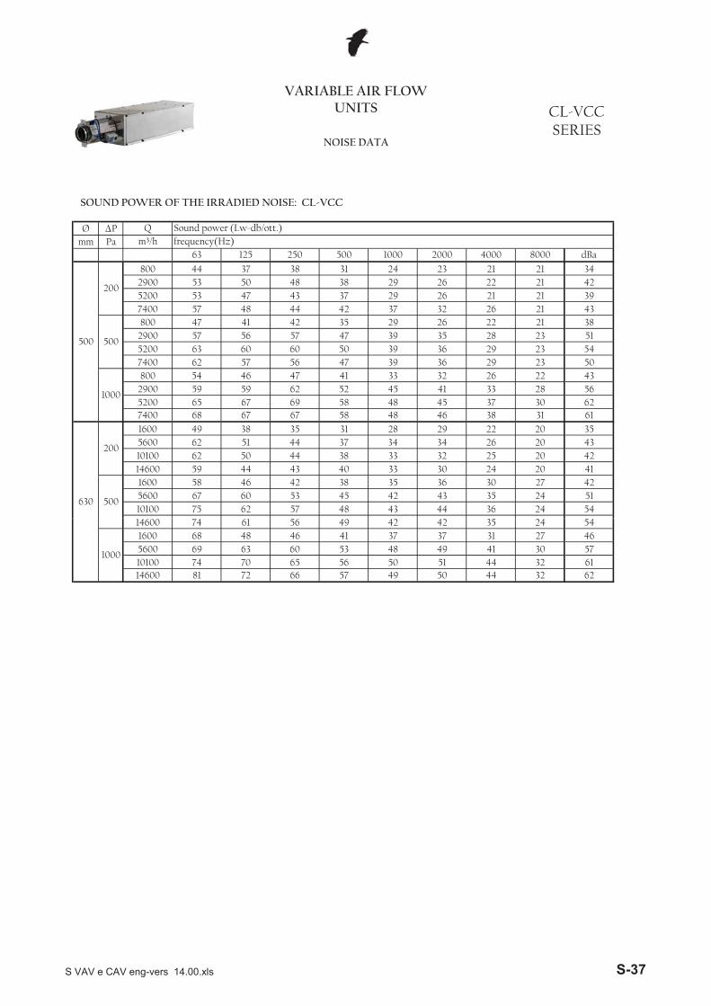
VARIABLE AIR FLOW UNITS CL-VCC
SERIESNOISE DATA
Q Sound power (Lw-db/ott.)
SOUND POWER OF THE GENERATED NOISE: CL-VCC
61 55 55 7060 56 53 70
14600 82 68 73 66 63
57 56 52 6610100 76 67 74 64 645600 70 68 66 59 61
47 59 49 45 47 6054 54 51 42 63
1000
1600 73 55 4714600 78 69 62 60
S VAV e CAV eng-vers 14.00.xls S-34
Ø �Pmm Pa
NOISE DATA
CL-VCCSERIES
VARIABLE AIR FLOW UNITS
Q Sound power (Lw-db/ott.)m³/h frequency(Hz)
63 125 250 2000 4000 8000 dBa
125
200
60 44 22 21220 45 31 35
500 1000
17 17 17 17 17 2530 22 17 3220 20
400 45 34 36 32 25 21 18 17 33570 45 33 36 32 26 21 17 17 33
500
60 33 23 24 22 19 19 17 17 26220 41 33 37 33 27 26 19 17 35400 45 42 45 43 35 31 23 19 43570 48 46 48 43 35 30 23 19 44
1000
60 35 25 27 26 22 22 20 18 2933 25 21 41220 41 38 43 39 34
400 46 42 46 44 38 37 27 23 45
SOUND POWER OF THE IRRADIED NOISE: CL-VCC
400 46 42 46 44 38 37 27 23 45570 49 46 49 44 38
160
200
100 41 25 24350 48 38 39
22 2836 27 23 46
21 1920 18 18 2234 25 19 35
700 56 42 46 39 30 24 20 19 41950 54 40 43 37 30 23 21 19 39
500
100 41 28 28 25 20 21 20 19 29350 49 39 44 39 30 26 22 20 40700 57 50 53 49 36 30 24 20 49950 53 53 54 48 38 31 25 21 49
1000
100 38 28 27 25 22 24 23 23 3132 26 24 45350 49 40 48 45 36
700 54 51 57 53 41 35 29 24 53950 53 53 57 55 41
200
200
230 37 30 31560 43 41 41
19 3035 29 24 54
25 2326 23 22 2033 27 22 36
1000 52 44 45 37 29 26 24 22 401500 53 44 43 37 31 26 24 20 39
500
230 46 36 38 32 26 24 22 20 35560 47 46 50 42 33 29 27 26 441000 53 52 55 47 37 35 33 30 491500 58 55 57 48 39 36 34 29 51
1000
230 47 41 44 37 31 27 25 24 3938 37 31 49560 53 46 53 46 41
1000 52 53 59 51 421500 56 60 63 54 44 40 37 35 57
38 35 33 53
S VAV e CAV eng-vers 14.00.xls S-35
Ø �Pmm Pa
64 63 63 54 44 42
250
200
250 40 33 34900 49 46 44
27 20 19 17 17 3034 25 22 18 17 38
1600 49 43 39 33 25 22 17 17 352300 53 44 40 38 33 28 22 17 39
500
250 43 37 38 31 25 22 18 17 34900 53 52 53 43 35 31 24 19 471600 59 56 56 46 35 32 25 19 502300 58 53 52 43 35 32 25 19 46
1000
250 50 42 43 37 29 28 22 18 39900 55 55 58 48 41 37 29 24 52
41 33 26 582300 571600 61 63 65 54 44
34 27
40 41 33 21 5139 40 32 21 48
2500 72 59 54 45
32 33 27 24 391500 64 57 50 42
27 21 17 38
500
400 55 43 39 35
29 22 17 393600 56 41 40 37 30
31 23 17 402500 59 47 41 35 30
26 19 17 321500 59 48 41 34 31
8000 dBa
315
200
400 46 35 32 28 25
m³/h frequency(Hz)63 125 250 500 1000 2000 4000
VARIABLE AIR FLOW UNITS CL-VCC
SERIESNOISE DATA
Q Sound power (Lw-db/ott.)
SOUND POWER OF THE IRRADIED NOISE: CL-VCC
39 31 28 5441 33 29 58
6300 76 64 53 48 40
37 30 29 534400 74 72 59 53 432500 66 66 54 49 40
35 28 26 24 21 4039 37 29 26 52
1000
700 59 51 41
38 36 28 24 536300 74 62 51 47
33 31 25 24 474400 73 66 54 47
25 22 19 18 352500 65 60 49 41
31 25 21 46
500
700 51 46 37 32
26 21 19 446300 66 56 46 43 35
21 18 17 374400 64 57 45 37 302500 58 49 38 30 24
23 18 18 17 17 2838 30 27 56
400
200
700 44 38 30
40 33 30 594800 78 65 58 51 42
37 31 28 523300 73 71 62 53 451800 65 62 56 49 42
36 30 27 22 20 3940 37 28 21 54
1000
500 58 48 38
39 36 27 25 534800 76 63 56 50
34 29 24 25 463300 72 62 57 48
25 21 19 18 341800 64 56 49 42
30 24 21 48
500
500 51 44 36 31
25 21 19 424800 68 56 51 46 36
21 18 17 353300 63 50 45 39 301800 57 44 35 30 24
25 20 18 17 17 2847 41 29 59
355
200
500 44 36 29
48 41 29 583600 78 69 63 54 46
46 38 27 542500 71 67 62 53 471500 66 60 57 50 45
38 34 34 28 24 4339 39 32 21 51
1000
400 65 45 433600 71 58 53 46
S VAV e CAV eng-vers 14.00.xls S-36
Ø �Pmm Pa
43 44 36 24 5442 43 35 24 51
10100 75 62 57 48
35 36 30 27 425600 67 60 53 45
30 24 20 41
500
1600 58 46 42 38
32 25 20 4214600 59 44 43 40 33
34 26 20 4310100 62 50 44 38 335600 62 51 44 37 34
31 28 29 22 20 3546 38 31 61
630
200
1600 49 38 35
45 37 30 627400 68 67 67 58 48
41 33 28 565200 65 67 69 58 482900 59 59 62 52 45
41 33 32 26 22 4339 36 29 23 50
1000
800 54 46 47
39 36 29 23 547400 62 57 56 47
39 35 28 23 515200 63 60 60 50
29 26 22 21 382900 57 56 57 47
32 26 21 43
500
800 47 41 42 35
26 21 21 397400 57 48 44 42 37
26 22 21 425200 53 47 43 37 29
23 21 21 342900 53 50 48 38 29
8000 dBa
500
200
800 44 37 38 31 24
m³/h frequency(Hz)63 125 250 500 1000 2000 4000
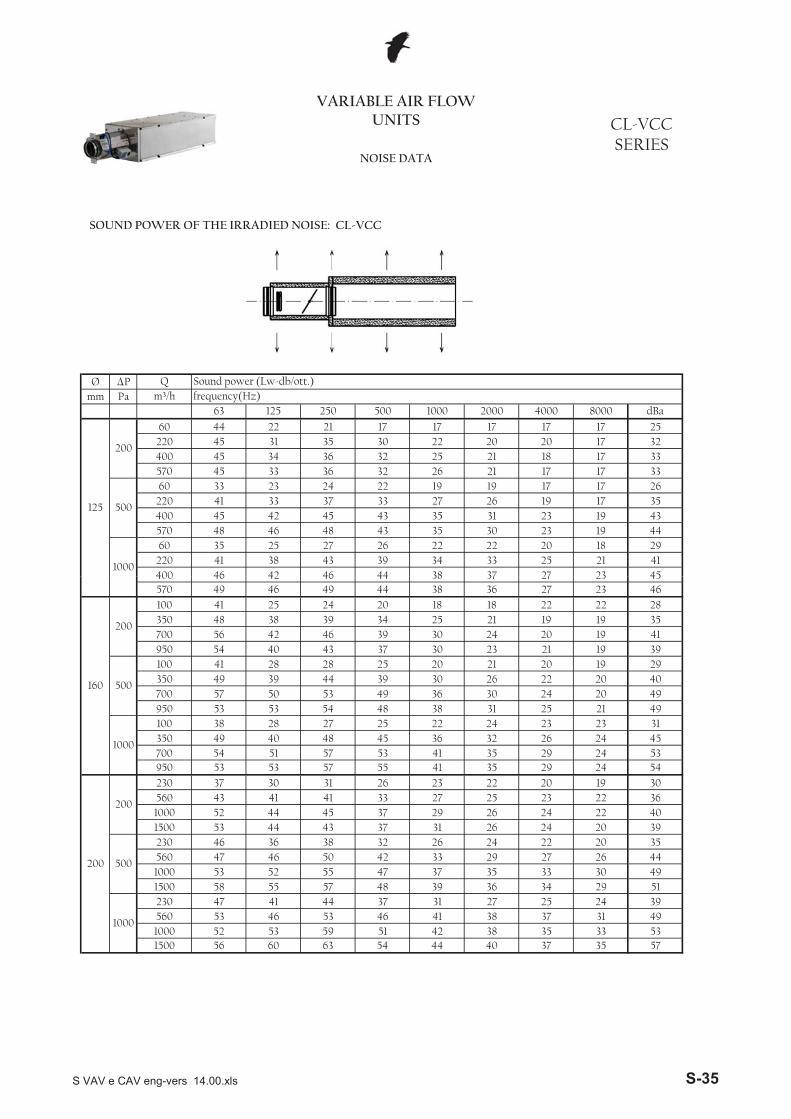
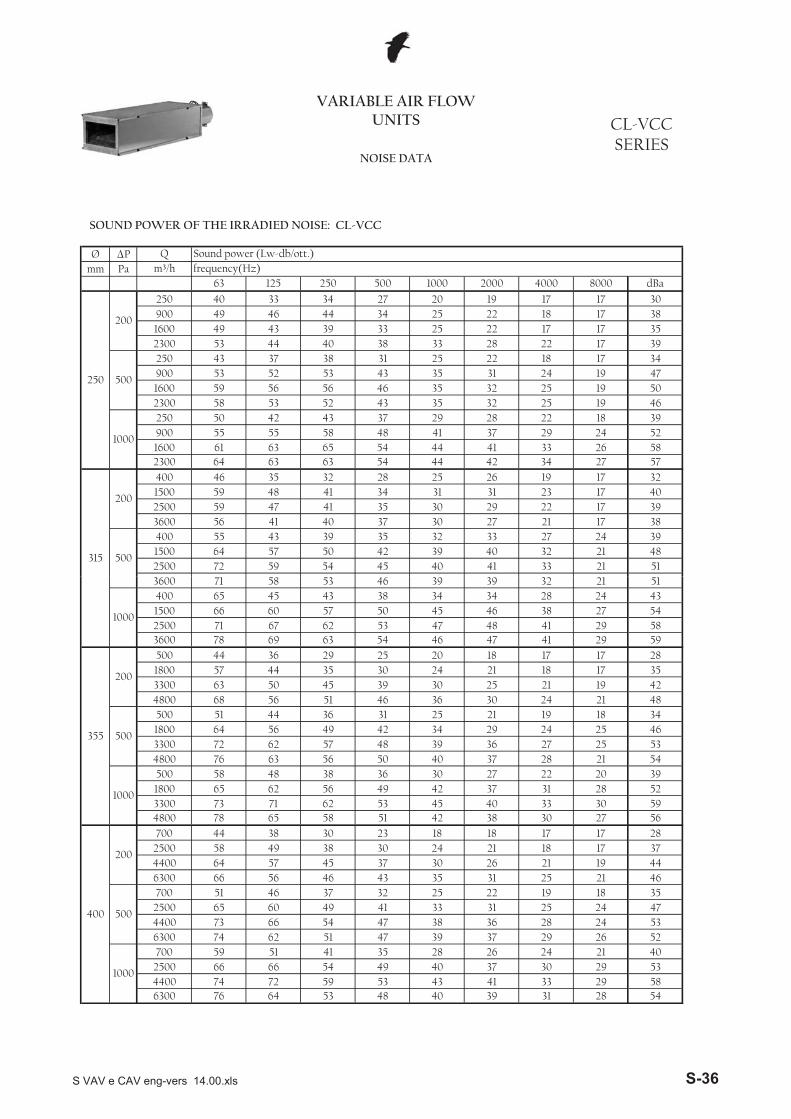
VARIABLE AIR FLOW UNITS CL-VCC
SERIESNOISE DATA
Q Sound power (Lw-db/ott.)
SOUND POWER OF THE IRRADIED NOISE: CL-VCC
50 44 32 6251 44 32 61
14600 81 72 66 57 49
49 41 30 5710100 74 70 65 56 505600 69 63 60 53 48
41 37 37 31 27 4642 42 35 24 54
1000
1600 68 48 4614600 74 61 56 49
S VAV e CAV eng-vers 14.00.xls S-37
Ø �Pmm Pa
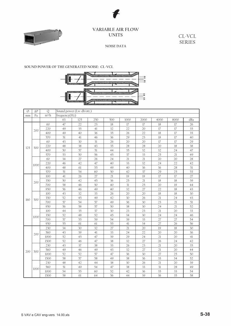
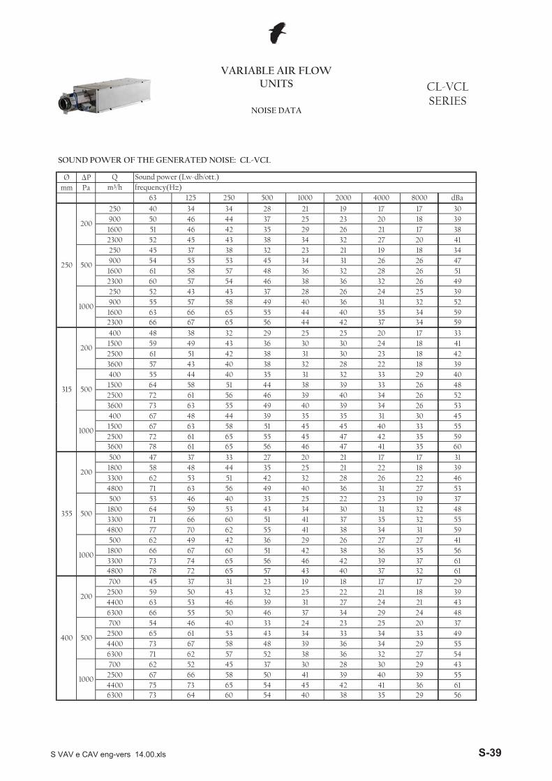
VARIABLE AIR FLOW UNITS CL-VCL
SERIESNOISE DATA
60
33
200
500220
53
4949220
400570
1000220400 61
6046
125
4524
30362635
2750
2217
35
1832
4035
2341
26
375738
51
4940
2133
20222320
1836463143
Qm³/h
60
400570
292028
44283235
181720
252024
32
3636
21202228
17171824
1717
1817
500
2132
40
Sound power (Lw-db/ott.)frequency(Hz)
dBa8000200063 1000125 4000250
38474928
35354029
425148
50
34
55
41
22
422647
48
56
5143
17 2647 17
SOUND POWER OF THE GENERATED NOISE: CL-VCL
5601000
1500
950
700
2305601000
1500230
100
950
700
350100
200
200
500
1000
1500
500
1000700950230
160
400570 60
6154
200
5049
2527
423636
37
221821
29171820
35
212127
2421242727
2132 27
36
23
3033
36
3334
202630302330
21
350 52 45 4932 3343
350 50 42 45
100
61 61
58 5735
31
21 19
46 49 40 325046
45 34
3049 3650
42
55 4157 55 5955
54 392427
18182421
19
28
26
57 54 57
251718
37
27 21 20 1833 24
192022
38 335601000
38
47
43242620
46 49 43 32 27
26 2736 25
1921
40
43
31
515327
4654
33
3944
345257 58 49 38 36
30
42 44 38 20
202637
3641
61
495458
4249
3555
33 28
58
44505239
5148
57
265460 52
30
36 3364 56 44
47 38
32
4746
413945 47
5630
25
2039 29 24 20
4235
3954
52
4851
52
4352
58
49
44
43515221
203856
30 23
23
58
55
56
41
2026
40
3034
524852
S VAV e CAV eng-vers 14.00.xls S-38
Ø �Pmm Pa
5040
61 57
52
44
3853
57 54
65
58
656766
58575563 66
3018 39
325251 46
25 23 20
2300
250
200
25090016002300
900
16002300
1000
250900
1600500
27250 3745
60
20
34 34 28 21 19 17 1746 37
4142 35 29 26 21 1743 38 34
46
49 40 3643 43
31 32
32 23 21
3848 36
24 2552
3445 34 31 26
32
19 18
39
5126 47
2849
26
263632
26
3845
34 5934 5955
37 28
44 40 3556 44 42 37
NOISE DATA
VARIABLE AIR FLOW UNITS CL-VCL
SERIES
18
3352
2626
4142394048
1829
250
18
Sound power (Lw-db/ott.)frequency(Hz)
dBa
33
8000
17
2000
25
57
150072
1000
39
4000
2024232233
3440
25003600400
125
384951
48
64
63
54 55
25303132
5961 38
32
4240
3030283231
38 394055
Qm³/h
4001500
4344
43
4461250058 51
56
35
315
200
500
2936
38
50046
SOUND POWER OF THE GENERATED NOISE: CL-VCL
1718
48
3330
35
39434837
594156616129
56
495554435561
55
5337
53455559
3946
6031
22
26
38
35
66
54 40 3842 3641
35
52 27322930
36
2973 65 54 4564 60
57
58 50 41 3952 45 37 30 28
3940
67 58 48 39 36 293462
46 40 33 24 233343 34 3433
2132 25
24242946 37
61 53
34
1863 53 46 39 31 27
6300700
25004400
250044006300
66
6300 71
54
73
73
65
6775
25
65
22
4240
700
45
62
59
50
72
55
39371721
78
20
56 46
37 3150 43
57 43
77
32700
25004400
23 19 18 1748003300 73 74 65
3542 36500 62 49 421800 66 67 60
66 60 51
34
27
37
27
314042
2638
27
19
70
5346 40
6237
593300 71 41
51
323231
36 294800
3300 62 53 51
33500 531800 64
4800 71 63 56
1800 58 48 44
55 38
27 20 21
22
41
2549
32
34
63
55
500 47
44
65
233135
4656
4551
40
43
36 31
22
35454747
21
48 35
25
63 40
6558
39
42
45
3600400
28
39
72
34
3741
33 17
30
2635
355
200
6161
7367
15002500
67
400
200
500
1000
78
500
1000
49
100055
3600
S VAV e CAV eng-vers 14.00.xls S-39
Ø �Pmm Pa
42 43 37 29 5541 42 36 29 51
10100 75 64 59 49
34 35 36 32 435600 67 61 54 47
31 25 21 42
500
1600 58 47 43 38
33 26 21 4514600 60 46 43 41 35
33 27 21 4310100 64 54 45 41 345600 62 52 46 39 33
32 28 28 23 20 3646 41 38 63
630
200
1600 51 41 35
44 39 38 637400 70 71 69 60 48
40 35 36 565200 67 70 69 59 482900 59 61 62 53 44
41 32 30 28 29 4342 40 36 30 53
1000
800 56 47 47
40 36 32 30 557400 64 61 58 50
38 35 30 30 515200 65 62 61 52
27 25 23 22 382900 58 59 57 49
36 31 24 45
500
800 49 41 42 36
30 25 21 427400 56 49 47 42 38
27 24 22 435200 55 50 46 39 33
23 21 21 342900 54 50 48 41 29
8000 dBa
500
200
800 44 38 38 32 25
m³/h frequency(Hz)63 125 250 500 1000 2000 4000
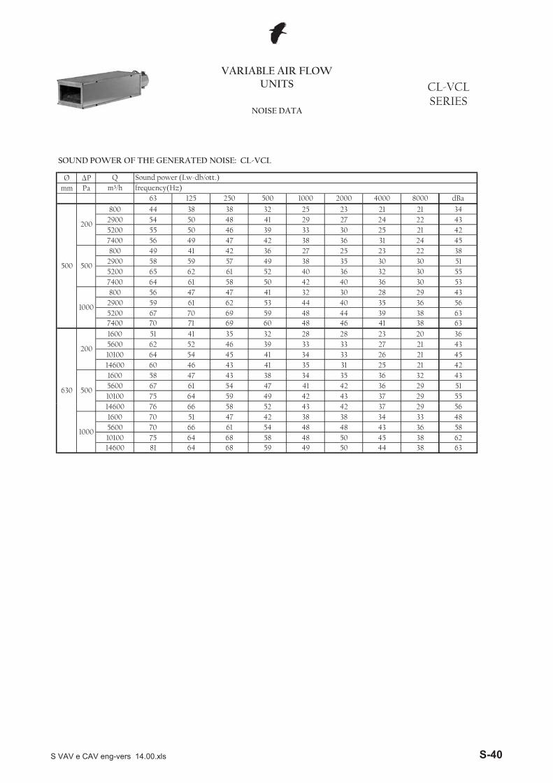
VARIABLE AIR FLOW UNITS CL-VCL
SERIESNOISE DATA
Q Sound power (Lw-db/ott.)
SOUND POWER OF THE GENERATED NOISE: CL-VCL
50 44 38 6350 45 38 62
14600 81 64 68 59 49
48 43 36 5810100 75 64 68 58 485600 70 66 61 54 48
42 38 38 34 33 4843 42 37 29 56
1000
1600 70 51 4714600 76 66 58 52
S VAV e CAV eng-vers 14.00.xls S-40
Ø �Pmm Pa
NOISE DATA
CL-VCLSERIES
VARIABLE AIR FLOW UNITS
4333
32
44294145
27
4545
332333
213536
30
222619
3233332635
171717
1717
Sound power (Lw-db/ott.)frequency(Hz)
dBa
25
8000
17
2000
17
63
44
191918202123
171719
262323
21
19
48
362437
38
4625
4000
17201832
172225
1000
20400
125
35
223134
250
21 17
45
25
Qm³/h
60220
500
39 3446 38
22
37
27
42
35434326
31302233
27
57060
22040057060
46
4835
45
220400
41
125
200
500
44
4533
43
4142
1000
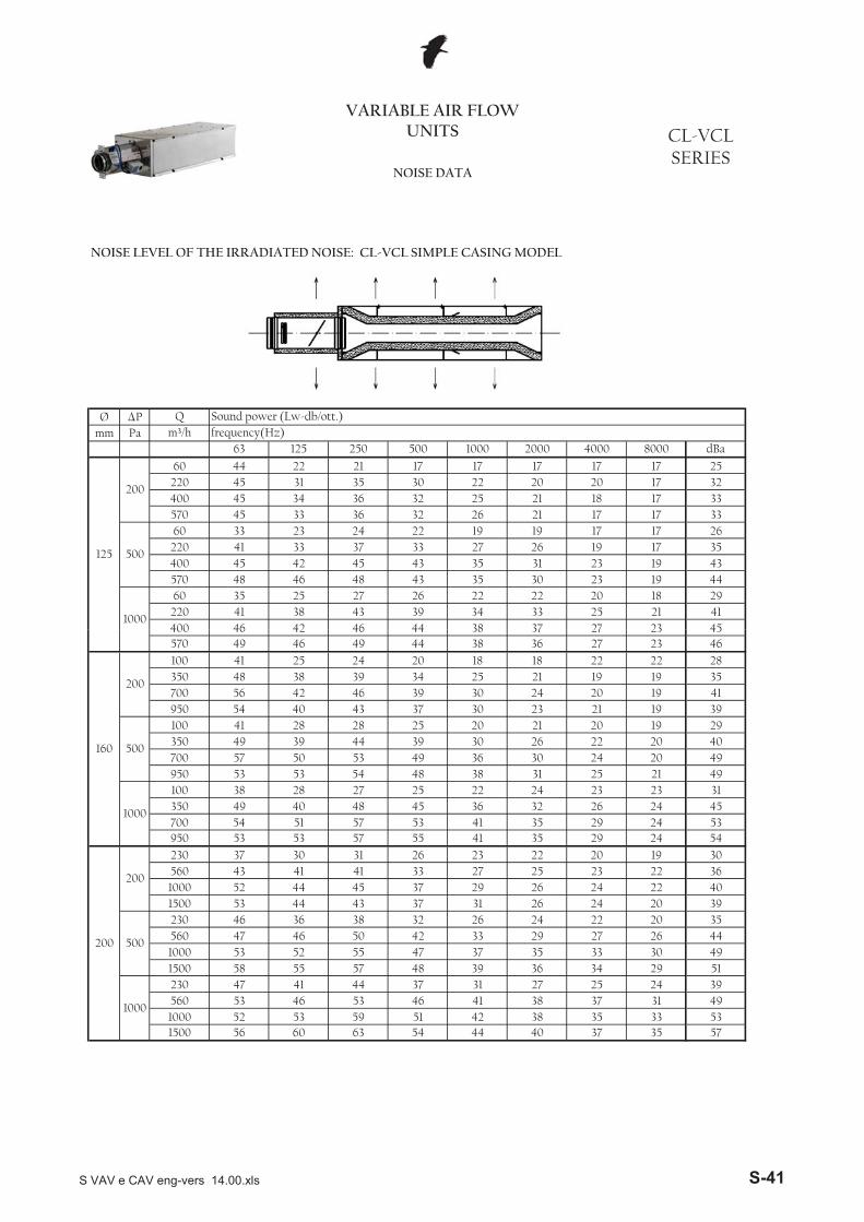
NOISE LEVEL OF THE IRRADIATED NOISE: CL-VCL SIMPLE CASING MODEL
283541
36
392940
39
4546
35
49
49493145535430
40
5357
44495139
53 59 51 42 38 333556 60 63 54 44 40 35
46 41 38 3137
293448 39 3637 31 27 2425
35 302742 3333
37 3122
29 2653 52 55 47 37
26 202446 36 38 32 26 24 20
37 29 26 2233 27 2223
24
37
1500
46 50
58 55 57
47
52
20
44
700 54 51 57950
43 41 41
52
15002305601000
242424
230560
4753
53 44 4345
41 4446
20212328 27
30 26 23 22 1953 53 57 29
53 4155 41
26
21 191920
21
25
2323221919
20
21
22
36
36 3031 25
24
2353
48 2629
25 20
2245
48 3854
24
49 40
700 57 50 53950 53
39 30
46
25
2432
20 1825
3739 30
30
3924 18
364649
383844
37
39
42 464028
44
42
28
31
53
49
43
34
27
23
221920
5704649
37
3535
1500
27
3825
400 44
1000
350
100350
700950
100
1000
5654
38
500
1000
500
1000350
230560
160
200
200
200
100 4148
4149
S VAV e CAV eng-vers 14.00.xls S-41
Ø �Pmm Pa
38
42
37
63 65 54 44 41
43 35 3228
5726 58
64 63 63 2754 44
37 29
46
1000
250 50 42 43 37 2952
33
18 39900 55 55 58 48 41
25
34
24 521600
22
502300 58 53
24
25 191600 59 56 56 46 35 32
17
19
34900 53 52 53 43 35 31
28
47
44 40 38 33
1925 22 18
3022 18 17 38
35
17
22 17 39
46 44 34 2522 17 17
19 1749
1600 49 39 33
33
43
40
43
61
250
2300
250
200
250
2300
500
CL-VCLSERIES
71
27
2000
57 323341
VARIABLE AIR FLOW UNITS
3548
4147
125
NOISE DATA
3530
34 27
315
200
50059
3600
1500
15002500
722500
250
324141
54 4558
40
Qm³/h
4005959
63
46
900
53
400 5564
403950
43563600
53 3946 39
42
32
3340 21
21
1717
3239
500
2834
3735
25
20
31
1000
253130
27
263129
2332
8000
17
1724
21
40393840
Sound power (Lw-db/ott.)frequency(Hz)
dBa4000
19
2221
485151
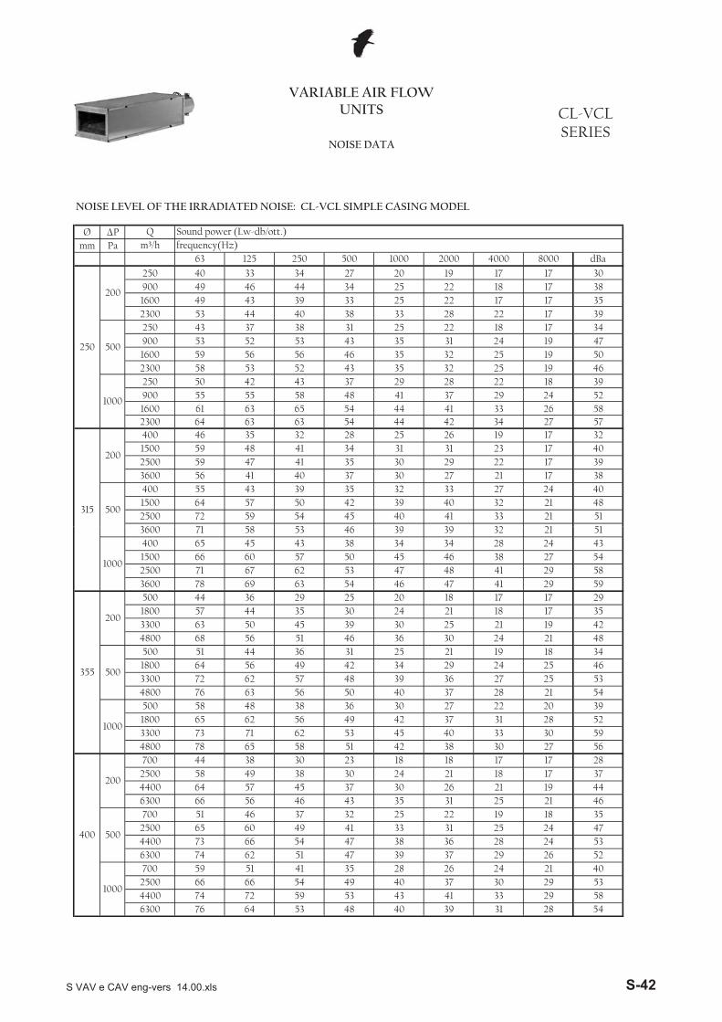
NOISE LEVEL OF THE IRRADIATED NOISE: CL-VCL SIMPLE CASING MODEL
7165
1000
3600
67
63
44
76
63
44
4560
400
3600 7836
571800
400
200
500
1000
500
1000
355
200
69
15002500
6671
4800
47
38 3458
4654
53435762
45
39
53
46 39
34
39
3446
212530
30
32
18
38
2129363727
33
24
414847
241924
21
2231
29
4800 68 56 513300 63
50035
500 511800 64 56
50
4037
39
44 36
3046 3631 25
45
53 45
36 3049 42
50
42
71 6262 56
3300 72
48 38
5762
4800 78
500 581800 653300 73
2840
49
5648
2838
27
4117
2425
2917
29
2427
21202830
21182525
17
17
65 58 301718
51 42
21
27700
25004400
23 18 18 1730 24
1841 33 31
1931 21
30
19
21
2528 24
2537 30 2643 35
21
6300700
25004400
6300700
25004400
65 60 49
66 66 5459 5174 62
66 5664 57 45
46 3746
51
6300
44 38 3058 49 38
41
74 72
51 47 39 37
31
24
26
332929
73 66 54 4729
2843 4159 53
3749 40
76 64 53 48 40 39
35
38
32 25
20
50
28 26
36
22
18
46
19
2143
54
47535240
535439
3744
5358
5458592935424834
4635
52595628
51
S VAV e CAV eng-vers 14.00.xls S-42
Ø �Pmm Pa
42 42 35 24 5443 44 36 24 54
14600 74 61 56 49
42 43 35 24 5110100 75 62 57 48
35 36 30 27 425600 67 60 53 45
30 24 20 41
500
1600 58 46 42 38
32 25 20 4214600 59 44 43 40 33
34 26 20 4310100 62 50 44 38 335600 62 51 44 37 34
31 28 29 22 20 3546 38 31 61
630
200
1600 49 38 35
45 37 30 627400 68 67 67 58 48
41 33 28 565200 65 67 69 58 482900 59 59 62 52 45
41 33 32 26 22 4339 36 29 23 50
1000
800 54 46 47
39 36 29 23 547400 62 57 56 47
39 35 28 23 515200 63 60 60 50
29 26 22 21 382900 57 56 57 47
32 26 21 43
500
800 47 41 42 35
26 21 21 397400 57 48 44 42 37
26 22 21 425200 53 47 43 37 29
23 21 21 342900 53 50 48 38 29
8000 dBa
500
200
800 44 37 38 31 24
m³/h frequency(Hz)63 125 250 500 1000 2000 4000
VARIABLE AIR FLOW UNITS CL-VCL
SERIESNOISE DATA
Q Sound power (Lw-db/ott.)
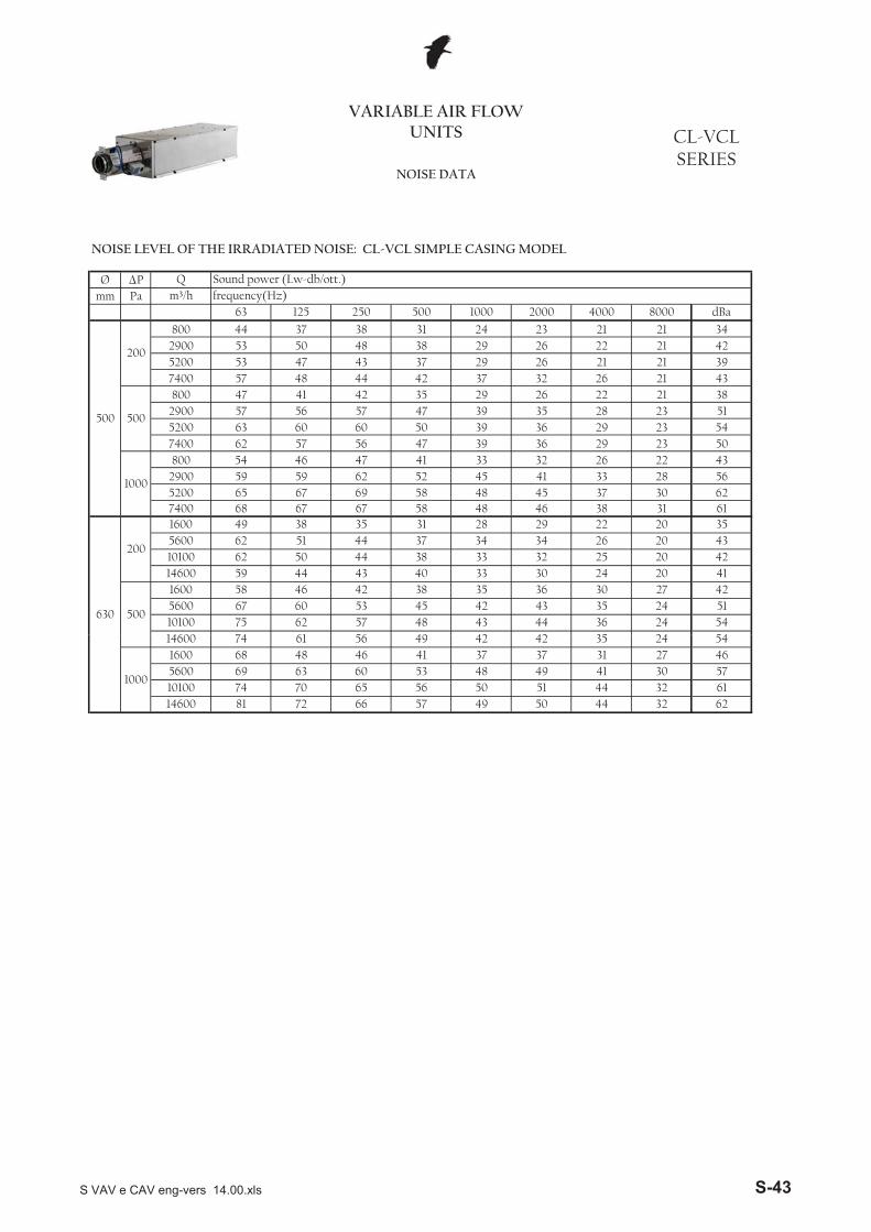
NOISE LEVEL OF THE IRRADIATED NOISE: CL-VCL SIMPLE CASING MODEL
50 44 32 6251 44 32 61
14600 81 72 66 57 49
49 41 30 5710100 74 70 65 56 505600 69 63 60 53 48
41 37 37 31 27 4642 42 35 24 54
1000
1600 68 48 4614600 74 61 56 49
S VAV e CAV eng-vers 14.00.xls S-43
Ø �Pmm Pa
26 18 15 3521 15 15 31
400 41 31 40 32 28220 37 29 36 29 23
19 15 15 15 15 2325 22 15 15 35
1000
60 32 16 20
26 23 15 15 34570 41 37 39 35
18 19 15 15 27400 38 35 36 34
15 15 15 15 22220 36 25 28 25
15 15 15 25
500
60 30 15 15 15
15 15 15 25570 42 25 23 24 17
15 15 15 24400 40 26 24 24 15
15 15 15 22220 40 22 24 21 15
8000 dBa
125
200
60 39 15 15 15 15
m³/h frequency(Hz)63 125 250 500 1000 2000 4000
VARIABLE AIR FLOW UNITS CL-VCL
SERIESNOISE DATA
Q Sound power (Lw-db/ott.)
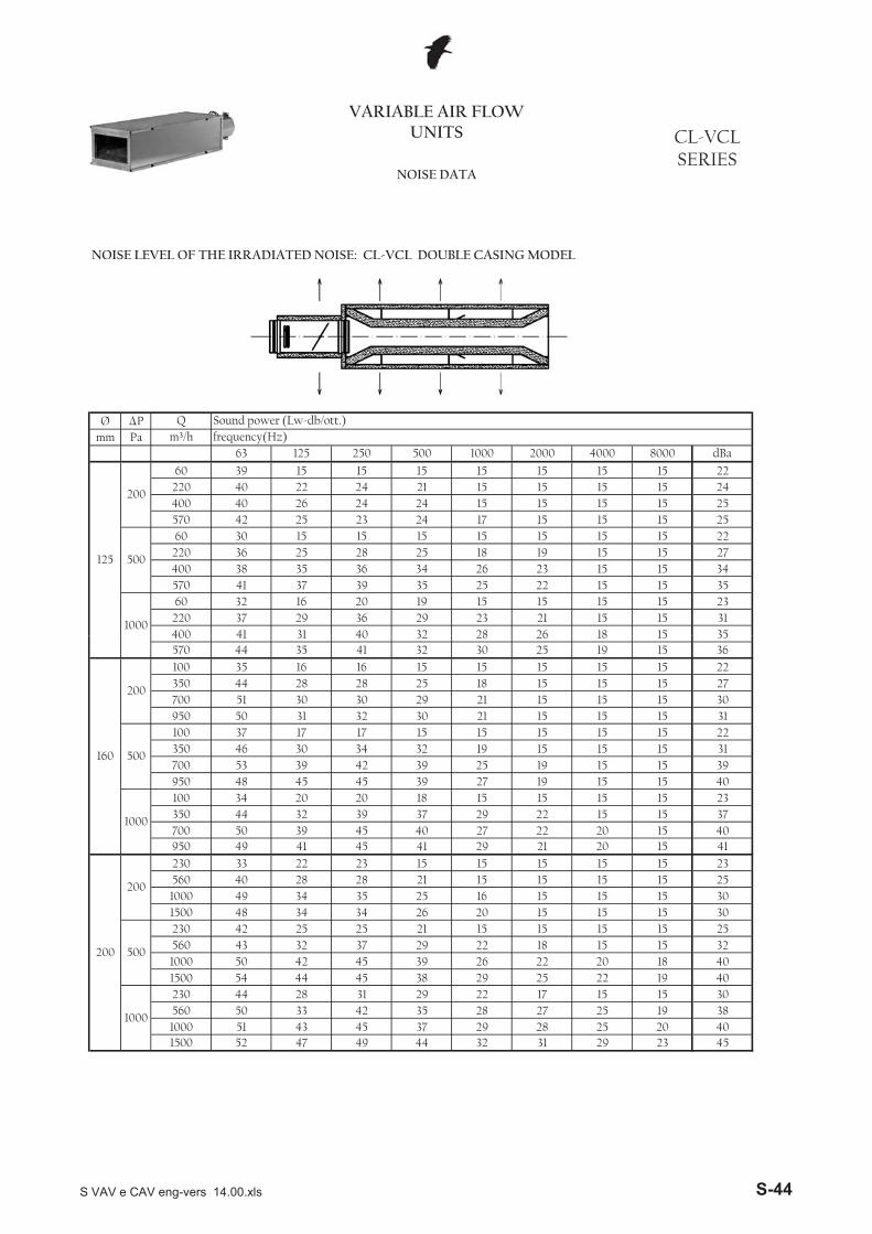
NOISE LEVEL OF THE IRRADIATED NOISE: CL-VCL DOUBLE CASING MODEL
31 29 23 4528 25 20 40
1500 52 47 49 44 32
27 25 19 381000 51 43 45 37 29560 50 33 42 35 28
29 22 17 15 15 3029 25 22 19 40
1000
230 44 28 31
26 22 20 18 401500 54 44 45 38
22 18 15 15 321000 50 42 45 39
15 15 15 15 25560 43 32 37 29
15 15 15 30
500
230 42 25 25 21
15 15 15 301500 48 34 34 26 20
15 15 15 251000 49 34 35 25 16560 40 28 28 21 15
15 15 15 15 15 2321 20 15 41
200
200
230 33 22 23
22 20 15 40950 49 41 45 41 29
22 15 15 37700 50 39 45 40 27350 44 32 39 37 29
18 15 15 15 15 2327 19 15 15 40
1000
100 34 20 20
25 19 15 15 39950 48 45 45 39
19 15 15 15 31700 53 39 42 39
15 15 15 15 22350 46 30 34 32
15 15 15 31
500
100 37 17 17 15
15 15 15 30950 50 31 32 30 21
15 15 15 27700 51 30 30 29 21350 44 28 28 25 18
15 15 15 15 15 2225 19 15 36
160
200
100 35 16 16
26 18 15 35570 44 35 41 32 30400 41 31 40 32 28
S VAV e CAV eng-vers 14.00.xls S-44
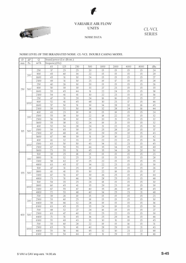
Ø �Pmm Pa
250
200
250 37 25 25900 45 40 34
20 15 15 15 15 2422 15 15 15 15 29
1600 45 31 30 24 15 15 15 15 272300 49 31 30 23 19 17 15 15 28
500
250 40 26 30 20 15 15 15 15 26900 50 39 39 33 27 23 15 15 351600 55 45 44 31 22 24 15 15 382300 54 41 41 30 22 23 15 15 36
1000
250 47 31 29 24 16 16 15 15 27900 52 41 45 48 30 23 17 15 461600 57 50 51 39 342300 59 52 50 38 32 28 24 16 44
28 20 16 45
29 20 15 432500 67 48 41 32 291500 59 45 39 29 25
21 22 15 15 3028 20 15 37
21 15 15 32
500
400 52 34 28 24
21 15 15 323600 55 38 32 24 192500 56 38 30 25 201500 55 38 30 22 18
18 15 15 2422 15 15 32
8000 dBa
315
200
400 43 23 19 19 15
m³/h frequency(Hz)63 125 250 500 1000 2000 4000
VARIABLE AIR FLOW UNITS CL-VCL
SERIESNOISE DATA
Q Sound power (Lw-db/ott.)
NOISE LEVEL OF THE IRRADIATED NOISE: CL-VCL DOUBLE CASING MODEL
29 22 21 4630 23 22 48
6300 70 54 44 42 314400 70 56 46 45 322500 65 51 41 40 28
15 16 15 3129 19 21 43
19 15 45
1000
700 55 40 28 22 19
16 15 466300 70 49 43 35 30 31
15 15 394400 71 51 45 36 25 29
15 15 272500 63 47 40 32 25 22
15 39
500
700 48 32 27 24 16 15
15 366300 63 45 35 35 24 19 15
15 304400 59 46 32 28 19 15 15
15 1515 15 15 1518 15
15 2325 23 21 48
400
200
700 39 26 192500 53 40 25
26 19 18 454800 72 53 48 40 343300 67 55 47 40 351800 60 45 41 35 29
15 15 15 3023 19 15 39
15 15 48
1000
500 54 35 25 24 18
15 15 444800 73 51 46 39 28 25
15 15 373300 67 51 47 39 26 25
15 15 261800 61 41 35 30 22 18
15 39
500
500 47 31 25 19 17 15
15 354800 63 45 37 34 22 23 15
15 283300 58 42 37 25 22 15 15
15 1515 15 15 1521 15
15 2334 26 20 50
355
200
500 39 25 181800 51 32 25
34 25 19 493600 73 55 51 45 352500 67 59 53 44 351500 63 50 50 43 34
22 22 15 15 3632 23 15 45
30 22 15 42
1000
400 61 32 33 273600 67 48 39 31 29
S VAV e CAV eng-vers 14.00.xls S-45
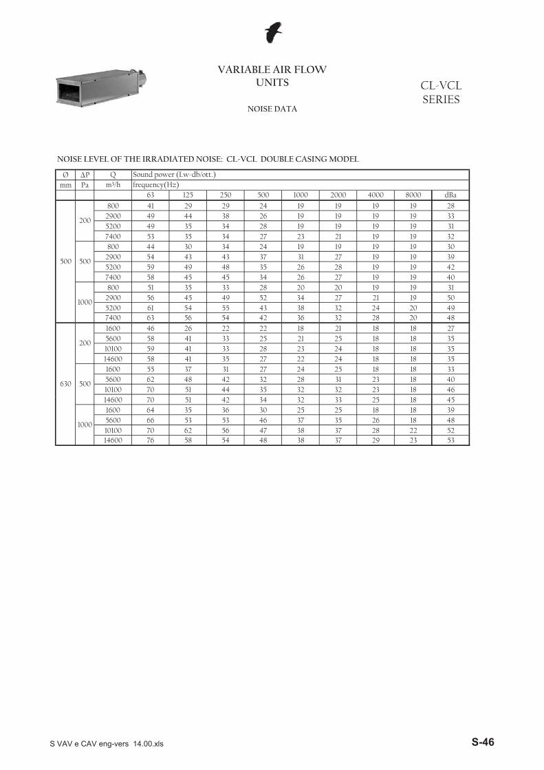
Ø �Pmm Pa
32 32 23 18 4628 31 23 18 40
10100 70 51 44 35
24 25 18 18 335600 62 48 42 32
24 18 18 35
500
1600 55 37 31 27
24 18 18 3514600 58 41 35 27 22
25 18 18 3510100 59 41 33 28 235600 58 41 33 25 21
22 18 21 18 18 2732 28 20 48
630
200
1600 46 26 22
32 24 20 497400 63 56 54 42 36
27 21 19 505200 61 54 55 43 382900 56 45 49 52 34
28 20 20 19 19 3126 27 19 19 40
1000
800 51 35 33
26 28 19 19 427400 58 45 45 34
31 27 19 19 395200 59 49 48 35
19 19 19 19 302900 54 43 43 37
21 19 19 32
500
800 44 30 34 24
19 19 19 317400 53 35 34 27 23
19 19 19 335200 49 35 34 28 19
19 19 19 282900 49 44 38 26 19
8000 dBa
500
200
800 41 29 29 24 19
m³/h frequency(Hz)63 125 250 500 1000 2000 4000
VARIABLE AIR FLOW UNITS CL-VCL
SERIESNOISE DATA
Q Sound power (Lw-db/ott.)
NOISE LEVEL OF THE IRRADIATED NOISE: CL-VCL DOUBLE CASING MODELNOISE LEVEL OF THE IRRADIATED NOISE: CL-VCL DOUBLE CASING MODEL
37 29 23 5337 28 22 52
14600 76 58 54 48 38
35 26 18 4810100 70 62 56 47 385600 66 53 53 46 37
30 25 25 18 18 3932 33 25 18 45
1000
1600 64 35 3614600 70 51 42 34
S VAV e CAV eng-vers 14.00.xls S-46
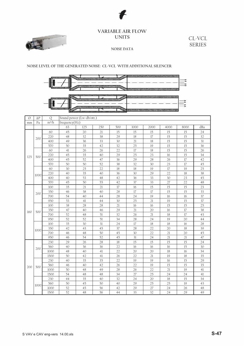
Ø �Pmm Pa
33 30 23 4529 22 18 38
400 40 53 48 42 36220 40 35 40 36 30
18 18 19 17 19 2532 30 23 17 45
1000
60 30 25 22
29 28 26 17 42570 50 50 52 38
25 23 16 15 34400 45 52 47 36
17 18 15 15 26220 45 35 40 29
19 15 15 36
500
60 41 26 26 22
18 15 15 31570 50 35 42 32 25
17 15 15 32400 49 36 33 30 21220 48 32 38 29 18
15 15 15 15 15 24
2000 4000 8000 dBa
125
200
60 45 20 21
63 125 250 500 1000
VARIABLE AIR FLOW UNITS
Q Sound power (Lw-db/ott.)m³/h frequency(Hz)
NOISE DATA
CL-VCLSERIES
NOISE LEVEL OF THE GENERATED NOISE: CL-VCL WITH ADDITIONAL SILENCER
29 4927 24 26 4832 241500 52 48 56 44 33
25 25 19 431000 52 45 56 42 29560 50 45 50 40 29
32 24 20 18 15 3427 25 24 24 41
1000
230 44 35 40
26 22 21 19 411500 54 48 48 34
22 19 15 15 351000 50 48 49 28
19 19 16 15 29560 46 40 42 26
21 19 18 35
500
230 40 35 35 22
20 18 16 341500 50 42 41 26 22
16 16 15 301000 48 40 41 22 20560 40 36 36 22 16
18 15 15 15 15 2424 21 21 47
200
200
230 29 26 28
22 21 20 45950 46 54 52 45 31
22 20 18 39700 46 48 50 45 30350 42 43 45 37 28
24 17 18 18 16 2828 24 19 20 44
1000
100 35 30 31
26 21 18 17 43950 52 52 51 34
21 20 16 17 38700 52 48 51 32
16 16 15 15 25350 47 40 46 29
21 19 15 37
500
100 38 28 28 21
19 16 16 37950 53 41 44 30 25
17 15 15 33700 54 40 44 28 24350 46 38 40 28 17
17 16 15 15 15 2333 27 22 48
160
200
100 35 21 21
33 30 23 45570 45 50 55 42 37400 40 53 48 42 36
S VAV e CAV eng-vers 14.00.xls S-47
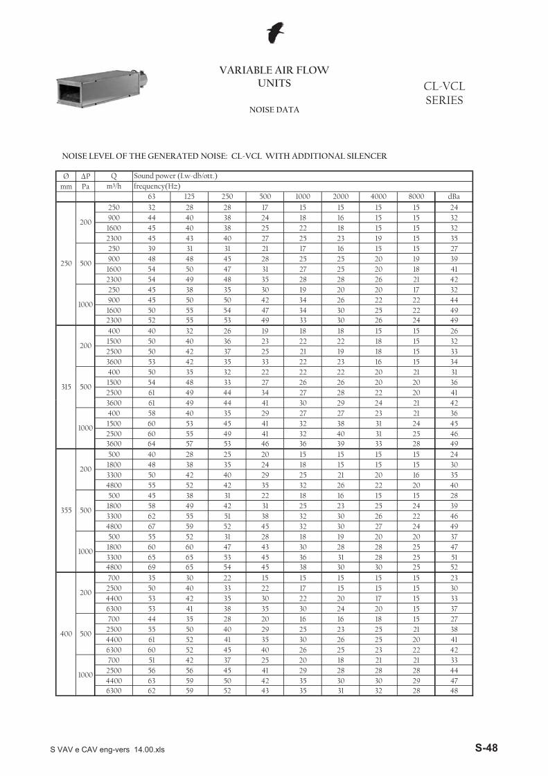
Ø �Pmm Pa
20
26 2452 55 53 49 33 3047 34
4930 25 22 49
23001600 50 55 54900 45 50 50 42 34
20 17 3226 22 22 44
1928 26 21 42
1000
250 45 38 35 30
25 20 18 412300 54 49 48 35 281600 54 50 47 31 27900 48 48 45 28 25
17 16 15 15 2725 20 19 39
23 19 15 35
500
250 39 31 31 212300 45 43 40 27 25
25 22 18 15 15 3216 15 15 32900 44 40 38 24 18
17 15 15 15 15 24
250
200
250 32 28 28
1600 45 40 38
22 20 4120 20 36
2500 61 49 44 34 27 28
20 21 311500 54 48 33 27 26 26
15 34
500
400 50 35 32 22 22 22
15 333600 53 42 35 33 22 23 16
15 322500 50 42 37 25 21 19 18
19 18 18 151500 50 40 36 23 22
15 26
315
200
400 40 32 2622 18
2000 4000 8000 dBa63 125 250 500 1000
VARIABLE AIR FLOW UNITS
Q Sound power (Lw-db/ott.)m³/h frequency(Hz)
NOISE DATA
CL-VCLSERIES
NOISE LEVEL OF THE GENERATED NOISE: CL-VCL WITH ADDITIONAL SILENCER
30 30 29 476300 4862 59 52 43
28 28 28 444400 63 59 50 42 352500 56 56 45 41 29
25 20 18 21 21 3326 25 23 22 42
1000
700 51 42 37
30 26 25 20 416300 60 52 45 40
25 23 25 21 384400 61 52 41 35
16 16 18 15 272500 55 50 40 29
24 20 15 37
500
700 44 35 28 206300 53 41 38 35 304400 53 42 35 30 22
22 17 15 15 15 3015 15 15 15 15 23
400
200
700 35 30 222500 50 40 33
35 31
25 52
32 28
20 17 15 33
30 3031 28 25 51
4800 69 65 54 45 383300 65 65 53 45 361800 60 60 47 43 30
19 20 20 3728 28 25 47
27 24 49
1000
500 55 52 31 28 18
26 22 464800 67 59 52 45 32 30
25 24 393300 62 55 51 38 32 30
15 15 281800 58 49 42 31 25 23
20 40
500
500 45 38 31 22 18 16
16 354800 55 52 42 35 32 26 22
15 303300 50 42 40 29 25 21 20
15 1520 15 15 1524 18
15 2439 33 28 49
355
200
500 40 28 251800 48 38 35
40 31 25 463600 64 57 53 46 362500 60 55 49 41 321500 60 53 45 41 32
27 23 21 3638 31 24 45
24 21 42
1000
400 58 40 35 29 273600 61 49 44 41 30 29
S VAV e CAV eng-vers 14.00.xls S-48
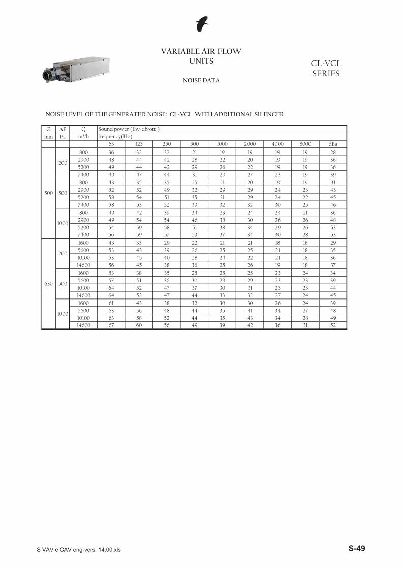
Ø �Pmm Pa
30 31 25 23 4429 29 23 23 39
10100 64 52 47 37
25 25 23 24 345600 57 51 36 30
26 19 18 37
500
1600 53 38 35 25
22 21 18 3614600 56 45 38 36 25
25 21 18 3510100 53 45 40 28 245600 53 43 39 26 25
22 21 21 18 18 2934 30 28 53
630
200
1600 43 35 29
34 29 26 537400 56 59 57 53 37
30 26 26 485200 54 59 58 51 382900 49 54 54 46 38
34 23 24 24 21 3632 32 30 25 46
1000
800 49 42 39
31 29 24 22 457400 58 53 52 39
29 29 24 23 435200 58 54 51 35
21 20 19 19 312900 52 52 49 32
27 23 19 39
500
800 43 35 35 25
22 19 19 367400 49 47 44 31 29
20 19 19 365200 49 44 42 29 26
19 19 19 282900 48 44 42 28 22
8000 dBa
500
200
800 36 32 32 21 19
m³/h frequency(Hz)63 125 250 500 1000 2000 4000
VARIABLE AIR FLOW UNITS CL-VCL
SERIESNOISE DATA
Q Sound power (Lw-db/ott.)
NOISE LEVEL OF THE GENERATED NOISE: CL-VCL WITH ADDITIONAL SILENCER
42 36 31 5243 34 28 49
14600 67 60 56 49 39
41 34 27 4810100 63 58 52 44 355600 63 56 48 44 35
32 30 30 26 24 3933 32 27 24 45
1000
1600 61 43 3814600 64 52 47 44
S VAV e CAV eng-vers 14.00.xls S-49
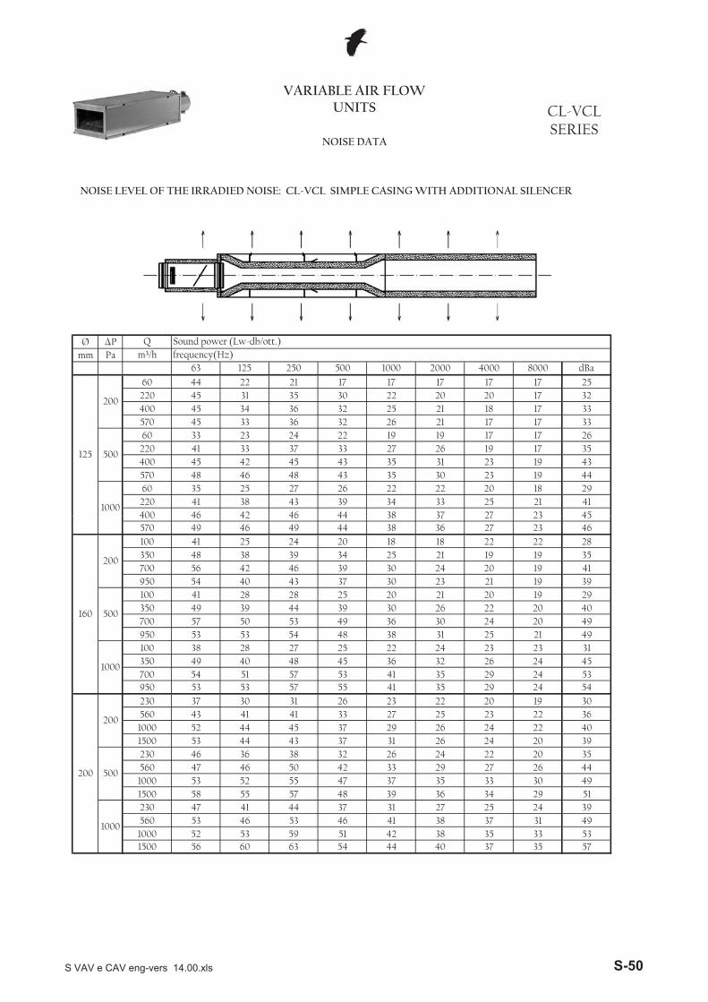
Ø �Pmm Pa
37 27 23 45400 46 42 46 44 38220 41 38 43 39 34
22 22 20 18 2933 25 21 41
30 23 19 44
1000
60 35 25 27 26
31 23 19 43570 48 46 48 43 35400 45 42 45 43 35220 41 33 37 33 27
19 19 17 17 2626 19 17 35
21 17 17 33
500
60 33 23 24 22570 45 33 36 32 26400 45 34 36 32 25220 45 31 35 30 22 20 20 17 32
21 18 17 33
17 17 17 17 17 25
2000 4000 8000 dBa
125
200
60 44 22 21
63 125 250 500 1000
VARIABLE AIR FLOW UNITS
Q Sound power (Lw-db/ott.)m³/h frequency(Hz)
NOISE DATA
CL-VCLSERIES
NOISE LEVEL OF THE IRRADIED NOISE: CL-VCL SIMPLE CASING WITH ADDITIONAL SILENCER
35 5738 35 33 5340 371500 56 60 63 54 44
1000 52 53 59 51 42560 53 46 53 46 41
27 25 24 3938 37 31 49
34 29 51
1000
230 47 41 44 37 31
33 30 491500 58 55 57 48 39 36
27 26 441000 53 52 55 47 37 35
22 20 35560 47 46 50 42 33 29
20 39
500
230 46 36 38 32 26 24
22 401500 53 44 43 37 31 26 24
22 361000 52 44 45 37 29 26 24
25 2326 23 22 2033 27
19 3035 29 24 54
200
200
230 37 30 31560 43 41 41
35 29 24 53950 53 53 57 55 41700 54 51 57 53 41350 49 40 48 45 36
24 23 23 3132 26 24 45
25 21 49
1000
100 38 28 27 25 22
24 20 49950 53 53 54 48 38 31
22 20 40700 57 50 53 49 36 30
20 19 29350 49 39 44 39 30 26
19 39
500
100 41 28 28 25 20 21
19 41950 54 40 43 37 30 23 21
19 35700 56 42 46 39 30 24 20
21 1920 18 18 2234 25
22 2836 27 23 46
160
200
100 41 25 24350 48 38 39
37 27 23 45570 49 46 49 44 38400 46 42 46 44 38
S VAV e CAV eng-vers 14.00.xls S-50
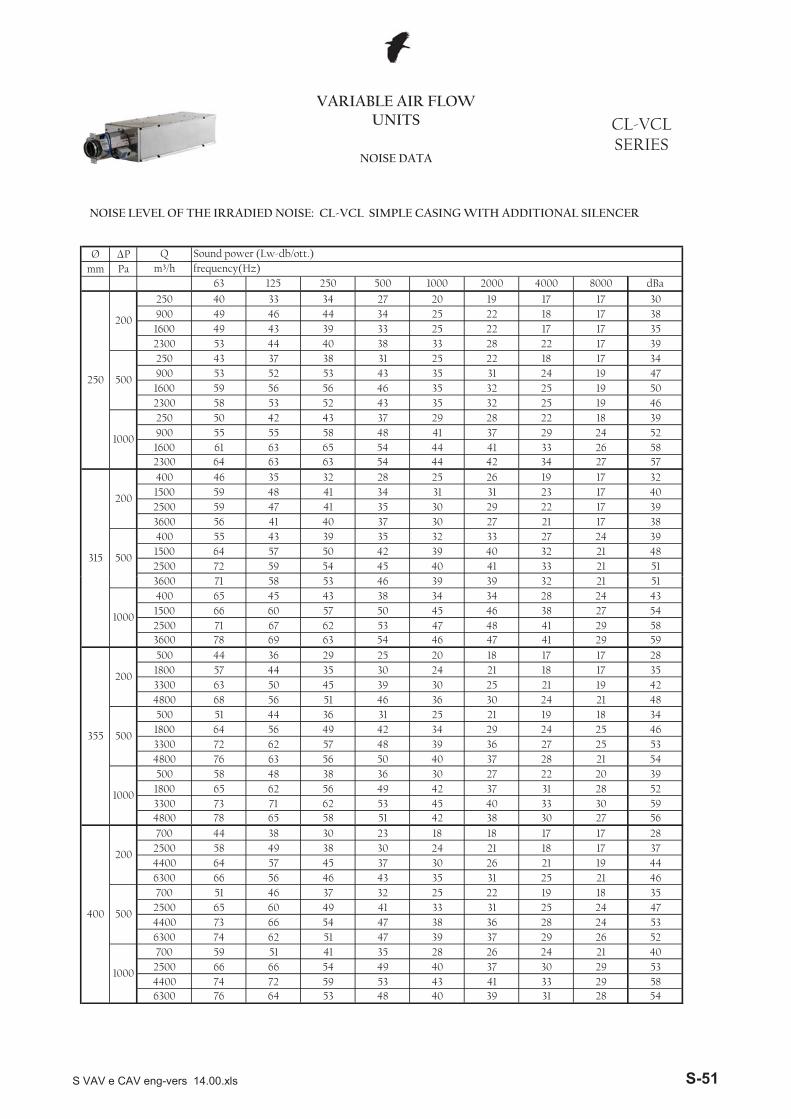
Ø �Pmm Pa
34 2764 63 63 54 44 42 5741 33 26 58
23001600 61 63 65 54 44900 55 55 58 48 41
29 28 22 18 3937 29 24 52
32 25 19 46
1000
250 50 42 43 37
32 25 19 502300 58 53 52 43 351600 59 56 56 46 35900 53 52 53 43 35
25 22 18 17 3431 24 19 47
28 22 17 39
500
250 43 37 38 312300 53 44 40 38 33
34 251600 49 43 39 33 25
22 18 17 3822 17 17 35
27 20 19 17 17 30
250
200
250 40 33 34900 49 46 44
33 21 5132 21 48
2500 72 59 54 45 40 41
27 24 391500 64 57 50 42 39 40
17 38
500
400 55 43 39 35 32 33
17 393600 56 41 40 37 30 27 21
17 402500 59 47 41 35 30 29 22
28 25 26 191500 59 48 41 34 31
17 32
315
200
400 46 35 3231 23
2000 4000 8000 dBa63 125 250 500 1000
VARIABLE AIR FLOW UNITS
Q Sound power (Lw-db/ott.)m³/h frequency(Hz)
NOISE DATA
CL-VCLSERIES
NOISE LEVEL OF THE IRRADIED NOISE: CL-VCL SIMPLE CASING WITH ADDITIONAL SILENCER
41 33 29 586300 5476 64 53 48
37 30 29 534400 74 72 59 53 432500 66 66 54 49 40
35 28 26 24 21 4039 37 29 26 52
1000
700 59 51 41
38 36 28 24 536300 74 62 51 47
33 31 25 24 474400 73 66 54 47
25 22 19 18 352500 65 60 49 41
31 25 21 46
500
700 51 46 37 326300 66 56 46 43 354400 64 57 45 37 30
30 24 21 18 17 3723 18 18 17 17 28
400
200
700 44 38 302500 58 49 38
40 39
27 56
31 28
26 21 19 44
40 33 30 5938 304800 78 65 58 51 42
3300 73 71 62 53 451800 65 62 56 49 42
27 22 20 3937 31 28 52
28 21 54
1000
500 58 48 38 36 30
27 25 534800 76 63 56 50 40 37
24 25 463300 72 62 57 48 39 36
19 18 341800 64 56 49 42 34 29
21 48
500
500 51 44 36 31 25 21
19 424800 68 56 51 46 36 30 24
17 353300 63 50 45 39 30 25 21
21 1825 20 18 1730 24
17 2847 41 29 59
355
200
500 44 36 291800 57 44 35
48 41 29 583600 78 69 63 54 462500 71 67 62 53 471500 66 60 57 50 45
34 28 24 4346 38 27 54
32 21 51
1000
400 65 45 43 38 343600 71 58 53 46 39 39
S VAV e CAV eng-vers 14.00.xls S-51
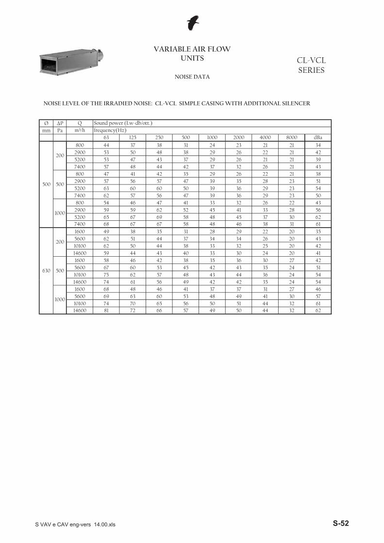
Ø �Pmm Pa
43 44 36 24 5442 43 35 24 51
10100 75 62 57 48
35 36 30 27 425600 67 60 53 45
30 24 20 41
500
1600 58 46 42 38
32 25 20 4214600 59 44 43 40 33
34 26 20 4310100 62 50 44 38 335600 62 51 44 37 34
31 28 29 22 20 3546 38 31 61
630
200
1600 49 38 35
45 37 30 627400 68 67 67 58 48
41 33 28 565200 65 67 69 58 482900 59 59 62 52 45
41 33 32 26 22 4339 36 29 23 50
1000
800 54 46 47
39 36 29 23 547400 62 57 56 47
39 35 28 23 515200 63 60 60 50
29 26 22 21 382900 57 56 57 47
32 26 21 43
500
800 47 41 42 35
26 21 21 397400 57 48 44 42 37
26 22 21 425200 53 47 43 37 29
23 21 21 342900 53 50 48 38 29
8000 dBa
500
200
800 44 37 38 31 24
m³/h frequency(Hz)63 125 250 500 1000 2000 4000
VARIABLE AIR FLOW UNITS CL-VCL
SERIESNOISE DATA
Q Sound power (Lw-db/ott.)
NOISE LEVEL OF THE IRRADIED NOISE: CL-VCL SIMPLE CASING WITH ADDITIONAL SILENCER
50 44 32 6251 44 32 61
14600 81 72 66 57 49
49 41 30 5710100 74 70 65 56 505600 69 63 60 53 48
41 37 37 31 27 4642 42 35 24 54
1000
1600 68 48 4614600 74 61 56 49
S VAV e CAV eng-vers 14.00.xls S-52
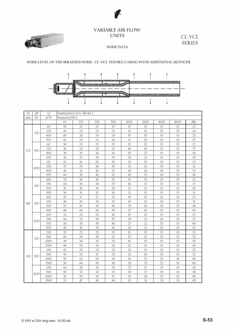
Ø �Pmm Pa
26 18 15 35400 41 31 40 32 28220 37 29 36 29 23
15 15 15 15 2321 15 15 31
22 15 15 35
1000
60 32 16 20 19
23 15 15 34570 41 37 39 35 25400 38 35 36 34 26220 36 25 28 25 18
15 15 15 15 2219 15 15 27
15 15 15 25
500
60 30 15 15 15
15 15 15 25570 42 25 23 24 17400 40 26 24 24 15220 40 22 24 21 15
15 15 15 2215 15 15 24
8000 dBa
125
200
60 39 15 15 15 15
m³/h frequency(Hz)63 125 250 500 1000 2000 4000
VARIABLE AIR FLOW UNITS CL-VCL
SERIESNOISE DATA
Q Sound power (Lw-db/ott.)
NOISE LEVEL OF THE IRRADIED NOISE: CL-VCL DOUBLE CASING WITH ADDITIONAL SILENCER
31 29 23 4528 25 20 40
1500 52 47 49 44 321000 51 43 45 37 29560 50 33 42 35 28
17 15 15 3027 25 19 38
22 19 40
1000
230 44 28 31 29 22
20 18 401500 54 44 45 38 29 25
15 15 321000 50 42 45 39 26 22
15 15 25560 43 32 37 29 22 18
15 30
500
230 42 25 25 21 15 15
15 301500 48 34 34 26 20 15 15
15 251000 49 34 35 25 16 15 15
15 1515 15 15 1521 15
15 2321 20 15 41
200
200
230 33 22 23560 40 28 28
22 20 15 40950 49 41 45 41 29700 50 39 45 40 27350 44 32 39 37 29
15 15 15 2322 15 15 37
15 15 40
1000
100 34 20 20 18 15
15 15 39950 48 45 45 39 27 19
15 15 31700 53 39 42 39 25 19
15 15 22350 46 30 34 32 19 15
15 31
500
100 37 17 17 15 15 15
15 30950 50 31 32 30 21 15 15
15 27700 51 30 30 29 21 15 15
15 1515 15 15 1525 18
15 2225 19 15 36
160
200
100 35 16 16350 44 28 28
26 18 15 35570 44 35 41 32 30400 41 31 40 32 28
S VAV e CAV eng-vers 14.00.xls S-53
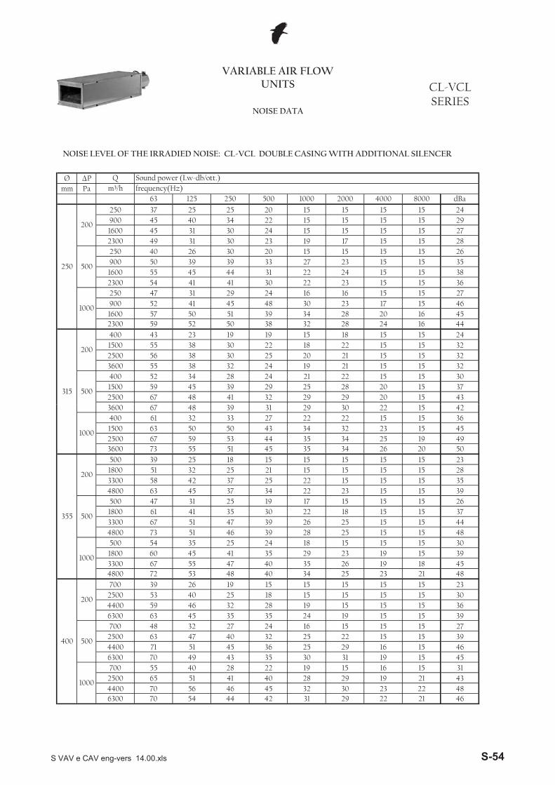
Ø �Pmm Pa
40 3415 24
250
200
250 37 25 25900 45 15 15
20 15 15 1522 15 15 29
1600 45 31 30 24 15 15 15 15 272300 49 31 30 23 19 17 15 15 28
500
250 40 26 30 20 15 15 15 15 26900 50 39 39 33 27 23 15 15 351600 55 45 44 31 22 24 15 15 382300 54 41 41 30 22 23 15 15 36
1000
250 47 31 29 24 16 16 15 15 2723 17 15 46900 52 41 45 48 30
1600 57 50 51 39 342300 59 52 50 38 32 28 24 16 44
28 20 16 45
29 20 15 432500 67 48 41 32 291500 59 45 39 29 25
21 22 15 15 3028 20 15 37
21 15 15 32
500
400 52 34 28 24
21 15 15 323600 55 38 32 24 192500 56 38 30 25 201500 55 38 30 22 18
18 15 15 2422 15 15 32
8000 dBa
315
200
400 43 23 19 19 15
m³/h frequency(Hz)63 125 250 500 1000 2000 4000
VARIABLE AIR FLOW UNITS CL-VCL
SERIESNOISE DATA
Q Sound power (Lw-db/ott.)
NOISE LEVEL OF THE IRRADIED NOISE: CL-VCL DOUBLE CASING WITH ADDITIONAL SILENCER
29 22 21 4630 23 22 48
6300 70 54 44 42 314400 70 56 46 45 322500 65 51 41 40 28
15 16 15 3129 19 21 43
19 15 45
1000
700 55 40 28 22 19
16 15 466300 70 49 43 35 30 31
15 15 394400 71 51 45 36 25 29
15 15 272500 63 47 40 32 25 22
15 39
500
700 48 32 27 24 16 15
15 366300 63 45 35 35 24 19 15
15 304400 59 46 32 28 19 15 15
15 1515 15 15 1518 15
15 2325 23 21 48
400
200
700 39 26 192500 53 40 25
26 19 18 454800 72 53 48 40 343300 67 55 47 40 351800 60 45 41 35 29
15 15 15 3023 19 15 39
15 15 48
1000
500 54 35 25 24 18
15 15 444800 73 51 46 39 28 25
15 15 373300 67 51 47 39 26 25
15 15 261800 61 41 35 30 22 18
15 39
500
500 47 31 25 19 17 15
15 354800 63 45 37 34 22 23 15
15 283300 58 42 37 25 22 15 15
15 1515 15 15 1521 15
15 2334 26 20 50
355
200
500 39 25 181800 51 32 25
34 25 19 493600 73 55 51 45 352500 67 59 53 44 351500 63 50 50 43 34
22 22 15 15 3632 23 15 45
30 22 15 42
1000
400 61 32 33 273600 67 48 39 31 29
S VAV e CAV eng-vers 14.00.xls S-54

Ø �Pmm Pa
32 32 23 18 4628 31 23 18 40
10100 70 51 44 35
24 25 18 18 335600 62 48 42 32
24 18 18 35
500
1600 55 37 31 27
24 18 18 3514600 58 41 35 27 22
25 18 18 3510100 59 41 33 28 235600 58 41 33 25 21
22 18 21 18 18 2732 28 20 48
630
200
1600 46 26 22
32 24 20 497400 63 56 54 42 36
27 21 19 505200 61 54 55 43 382900 56 45 49 52 34
28 20 20 19 19 3126 27 19 19 40
1000
800 51 35 33
26 28 19 19 427400 58 45 45 34
31 27 19 19 395200 59 49 48 35
19 19 19 19 302900 54 43 43 37
21 19 19 32
500
800 44 30 34 24
19 19 19 317400 53 35 34 27 23
19 19 19 335200 49 35 34 28 19
19 19 19 282900 49 44 38 26 19
8000 dBa
500
200
800 41 29 29 24 19
m³/h frequency(Hz)63 125 250 500 1000 2000 4000
VARIABLE AIR FLOW UNITS CL-VCL
SERIESNOISE DATA
Q Sound power (Lw-db/ott.)
NOISE LEVEL OF THE IRRADIED NOISE: CL-VCL DOUBLE CASING WITH ADDITIONAL SILENCER
37 29 23 5337 28 22 52
14600 76 58 54 48 38
35 26 18 4810100 70 62 56 47 385600 66 53 53 46 37
30 25 25 18 18 3932 33 25 18 45
1000
1600 64 35 3614600 70 51 42 34
S VAV e CAV eng-vers 14.00.xls S-55
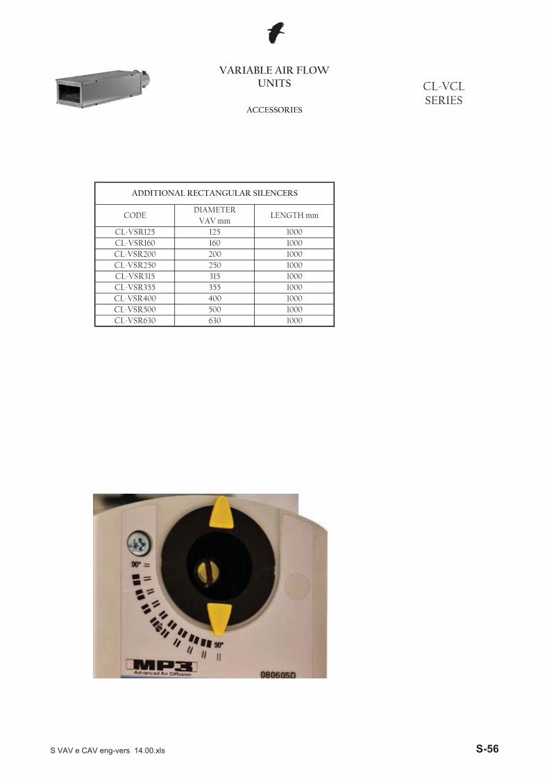
CL-VSR400 400 1000
CL-VSR250 250 1000
CL-VSR3551000
355 1000
125 1000VAV mm
CL-VSR160 160 1000
CODE
CL-VCLSERIES
ACCESSORIES
VARIABLE AIR FLOW UNITS
DIAMETERLENGTH mm
CL-VSR125
CL-VSR200
ADDITIONAL RECTANGULAR SILENCERS
CL-VSR315 315
200 1000
CL-VSR630 630 1000CL-VSR500 500 1000
S VAV e CAV eng-vers 14.00.xls S-56
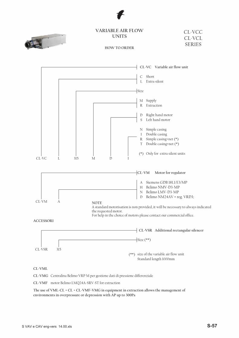
CL
MR Extraction
DS
NIRT
(*)
CL-VCC CL-VCL SERIES
M315CL-VC
VARIABLE AIR FLOW UNITS
CL-VC Variable air flow unit
Right hand motor
L D I
ShortExtra silent
Size
Supply
HOW TO ORDER
Simple casingDouble casing
Double casing+net (*)
Left hand motor
Only for extra silent units
Simple casing+net (*)
CL-VM Motor for regulator
AHND
(**) size of the variable air flow unitStandard length 1000mm
CL-VM A
ACCESSORI
Additional rectangular silencer
CL-VSR
The use of VML-CL + CL + CL-VMF-VMG in equipment in extraction allows the management of environments in overpressure or depression with AP up to 300Pa
CL-VML
CL-VMG Centralina Belimo VRP M per gestione dati di pressione differenziale
CL-VMF motor Belimo LMQ24A-SRV-ST for extraction
315
Siemens GDB 181.1/E3/MPBelimo NMV-D3-MP
Size (**)
Belimo NM24AV + reg. VRD3;
CL-VSR
Belimo LMV-D3-MP
g
NOTEA standard motorisation is non provided, it will be necessary to always indicated the requested motor.For help in the choice of motors please contact our commercial office.
S VAV e CAV eng-vers 14.00.xls S-57
S VAV e CAV eng-vers 14.00.xls S-58
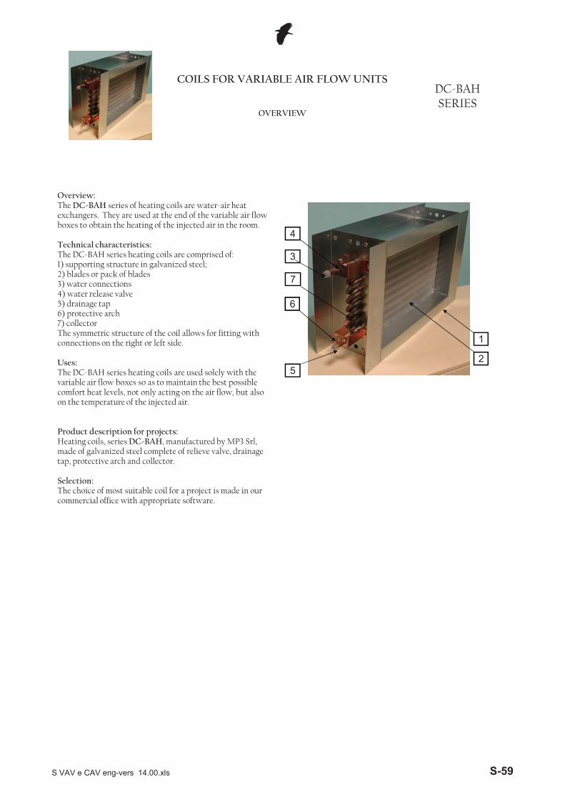
DC-BAH SERIES
COILS FOR VARIABLE AIR FLOW UNITS
OVERVIEW
Overview:The DC-BAH series of heating coils are water-air heat exchangers. They are used at the end of the variable air flow boxes to obtain the heating of the injected air in the room.
Technical characteristics:The DC-BAH series heating coils are comprised of:1) supporting structure in galvanized steel;2) blades or pack of blades3) water connections4) water release valve5) drainage tap6) protective arch7) collectorThe symmetric structure of the coil allows for fitting with connections on the right or left side.
Uses:The DC-BAH series heating coils are used solely with the variable air flow boxes so as to maintain the best possible comfort heat levels, not only acting on the air flow, but also on the temperature of the injected air.
2
1
3
4
5
66
7
Product description for projects: Heating coils, series DC-BAH, manufactured by MP3 Srl, made of galvanized steel complete of relieve valve, drainage tap, protective arch and collector.
Selection:The choice of most suitable coil for a project is made in our commercial office with appropriate software.
S VAV e CAV eng-vers 14.00.xls S-59
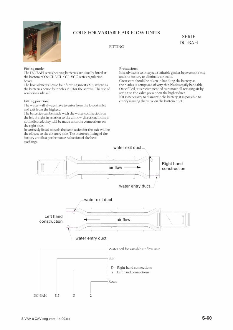
COILS FOR VARIABLE AIR FLOW UNITSSERIE
DC-BAHFITTING
Fitting mode:The DC-BAH series heating batteries are usually fitted at the bottom of the CL-VCL o CL-VCC series regulation boxes.The box silencers house four filtering inserts M8, where as the batteries house four holes Ø10 for the screws. The use of washers is advised.
Fitting position:The water will always have to enter from the lowest inlet and exit from the highest. The batteries can be made with the water connections on the left of right in relation to the air flow direction. If this is not indicated, they will be made with the connections on the right side.In correctly fitted models the connection for the exit will be the closest to the air entry side. The incorrect fitting of the battery entails a performance reduction of the heat exchange.
Precautions: It is advisable to interject a suitable gasket between the box and the battery to eliminate air leaks.Great care should be taken in handling the battery as the blades is composed of very thin blades easily bendable.Once filled, it is recommended to remove all remaing air by acting on the valve present on the higher duct.If it is necessary to dismantle the battery, it is possible to empty is using the valve on the bottom duct.
water exit duct
air flowRight hand construction
DS
Right hand connectionsLeft hand connections
Rows
DC-BAH 315 D 2
Water coil for variable air flow unit
Size
water entry duct
water exit duct
water entry duct
air flowLeft hand
construction
S VAV e CAV eng-vers 14.00.xls S-60
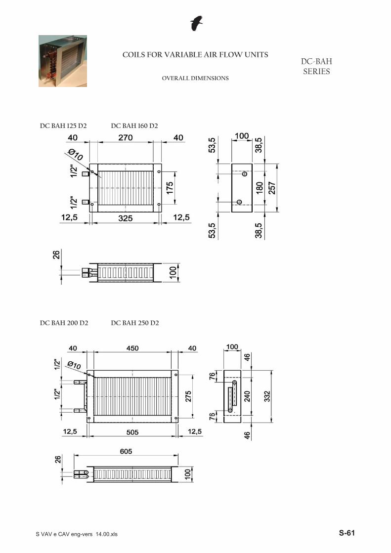
DC BAH 125 D2 DC BAH 160 D2
DC-BAH SERIES
COILS FOR VARIABLE AIR FLOW UNITS
OVERALL DIMENSIONS
DC BAH 200 D2 DC BAH 250 D2
S VAV e CAV eng-vers 14.00.xls S-61
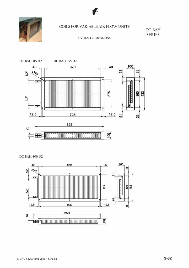
DC BAH 315 D2 DC BAH 355 D2
COILS FOR VARIABLE AIR FLOW UNITSDC-BAH SERIES
OVERALL DIMENSIONS
DC BAH 400 D2
S VAV e CAV eng-vers 14.00.xls S-62
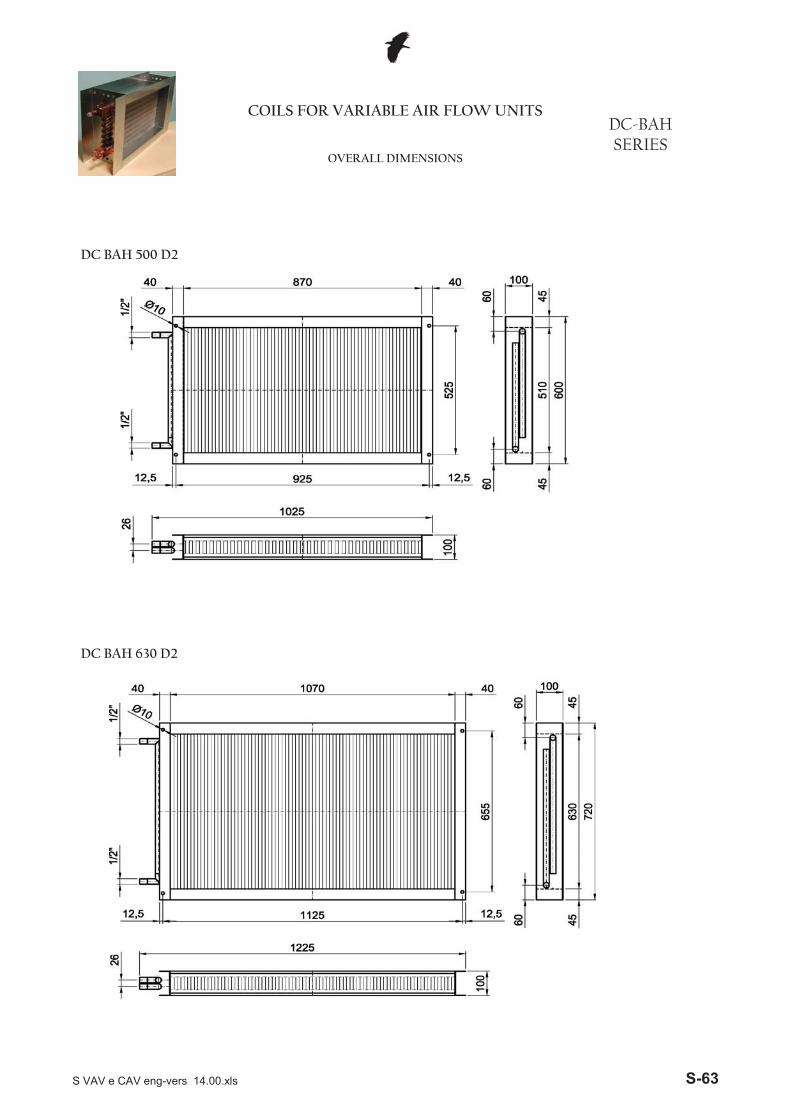
DC BAH 500 D2
COILS FOR VARIABLE AIR FLOW UNITSDC-BAH SERIES
OVERALL DIMENSIONS
DC BAH 630 D2
S VAV e CAV eng-vers 14.00.xls S-63

S VAV e CAV eng-vers 14.00.xls S-64
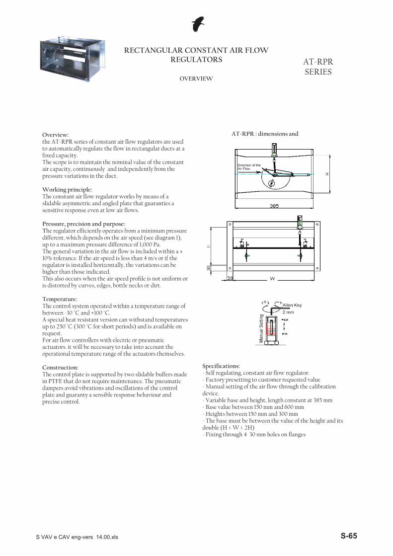
RECTANGULAR CONSTANT AIR FLOW REGULATORS AT-RPR
SERIESOVERVIEW
Overview:the AT-RPR series of constant air flow regulators are used to automatically regulate the flow in rectangular ducts at a fixed capacity.The scope is to maintain the nominal value of the constant air capacity, continuously and independently from the pressure variations in the duct.
Working principle:The constant air flow regulator works by means of a slidable asymmetric and angled plate that guaranties a sensitive response even at low air flows.
Pressure, precision and purpose:The regulator efficiently operates from a minimum pressure different, which depends on the air speed (see diagram 1), up to a maximum pressure difference of 1,000 Pa.The general variation in the air flow is included within a ±10% tolerance. If the air speed is less than 4 m/s or if the regulator is installed horizontally, the variations can be higher than those indicated.This also occurs when the air speed profile is not uniform or is distorted by curves edges bottle necks or dirt
AT-RPR : dimensions and
is distorted by curves, edges, bottle necks or dirt.
Temperature:The control system operated within a temperature range of between -30 °C and +100 °C. A special heat resistant version can withstand temperatures up to 250 °C (300 °C for short periods) and is available on request.For air flow controllers with electric or pneumatic actuators. it will be necessary to take into account the operational temperature range of the actuators themselves.
Construction:The control plate is supported by two slidable buffers made in PTFE that do not require maintenance. The pneumatic dampers avoid vibrations and oscillations of the control plate and guaranty a sensible response behaviour and precise control.
Specifications:- Self regulating, constant air flow regulator.- Factory presetting to customer requested value- Manual setting of the air flow through the calibration device.- Variable base and height, length constant at 385 mm- Base value between 150 mm and 600 mm- Heights between 150 mm and 300 mm- The base must be between the value of the height and its double (H � W � 2H)- Fixing through 4 30 mm holes on flanges
S VAV e CAV eng-vers 14.00.xls S-65
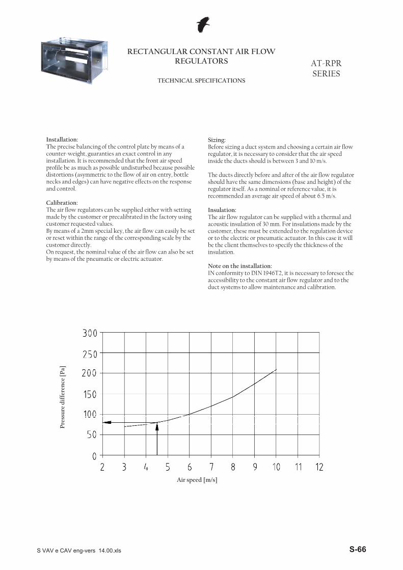
RECTANGULAR CONSTANT AIR FLOW REGULATORS AT-RPR
SERIESTECHNICAL SPECIFICATIONS
Installation:The precise balancing of the control plate by means of a counter-weight, guaranties an exact control in any installation. It is recommended that the front air speed profile be as much as possible undisturbed because possible distortions (asymmetric to the flow of air on entry, bottle necks and edges) can have negative effects on the response and control.
Calibration:The air flow regulators can be supplied either with setting made by the customer or precalibrated in the factory using customer requested values. By means of a 2mm special key, the air flow can easily be set or reset within the range of the corresponding scale by the customer directly.On request, the nominal value of the air flow can also be set by means of the pneumatic or electric actuator.
Sizing:Before sizing a duct system and choosing a certain air flow regulator, it is necessary to consider that the air speed inside the ducts should is between 3 and 10 m/s.
The ducts directly before and after of the air flow regulator should have the same dimensions (base and height) of the regulator itself. As a nominal or reference value, it is recommended an average air speed of about 6.5 m/s.
Insulation:The air flow regulator can be supplied with a thermal and acoustic insulation of 30 mm. For insulations made by the customer, these must be extended to the regulation device or to the electric or pneumatic actuator. In this case it will be the client themselves to specify the thickness of the insulation.
Note on the installation:IN conformity to DIN 1946T2, it is necessary to foresee the accessibility to the constant air flow regulator and to the duct systems to allow maintenance and calibration.
Air speed [m/s]
Pre
ssur
e d
iffe
renc
e [P
a]
S VAV e CAV eng-vers 14.00.xls S-66
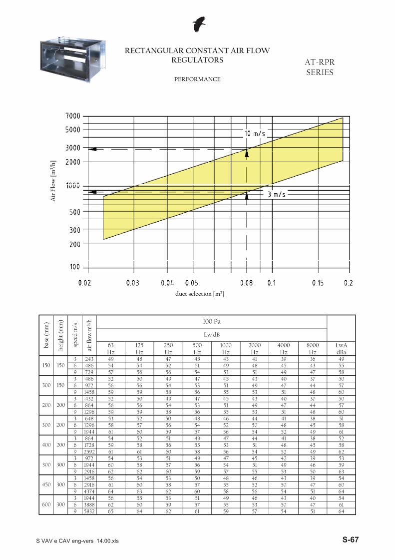
RECTANGULAR CONSTANT AIR FLOW REGULATORS AT-RPR
SERIESPERFORMANCE
Air
Flo
w [
m3 /
h]
3 2436 4869 7293 4866 9729 14583 4326 8649 12963 6486 12969 19443 8646 17289 25923 9726 19449 29163 14586 29169 43743 19446 38889 5832
6165 64 62 61 59 57 54 51 64
40 5462 60 59 57 55 53 50 47
64
600 30056 55 53 51 49 46 43
47 6064 63 62 60 58 56 54 51
43 39 5461 60 58 57 55 52 50
50 63
450 30056 54 53 50 48 46
49 46 5962 62 60 59 57 55 53
45 42 39 5360 58 57 56 54 51
52 49 62
300 30054 53 51 49 47
51 48 45 5861 61 60 58 56 54
47 44 41 38 5259 58 56 55 53400 20054 52 51 49
5861 60 59 57 56 54 52 49 61
38 5158 57 56 54 52 50 48 45
60
300 20053 52 50 48 46 44 41
44 5759 59 58 56 55 53 51 48
40 37 5056 56 54 53 51 49 47
48 60
200 20052 50 49 47 45 43
47 44 5759 59 58 56 55 53 51
43 40 37 5056 56 54 53 51 49
49 47 58
300 15052 50 49 47 45
48 45 43 5557 56 56 54 53 51
43 41 39 36 4954 54 52 51 49150 15049 48 47 45
LwAHz Hz Hz Hz Hz Hz Hz Hz dBa
Lw dB
63 125 250 500 1000 2000 4000 8000base
(m
m)
heig
ht (
mm
)
spee
d m
/s
air
flow
m³/
h 100 Pa
duct selection [m2]
S VAV e CAV eng-vers 14.00.xls S-67
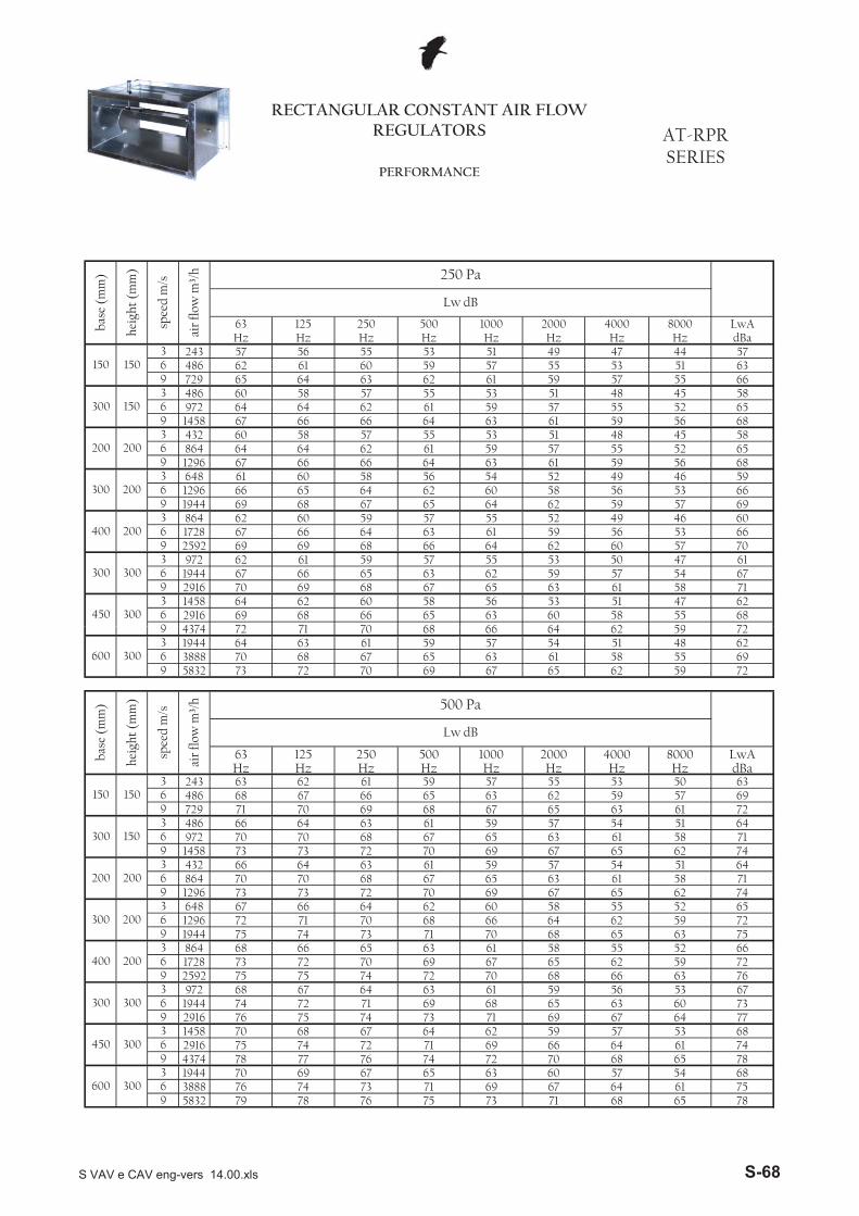
3 2436 4869 7293 4866 9729 14583 4326 8649 12963 6486 12969 19443 8646 17289 25923 9726 19449 29163 14586 29169 4374 72
55 6872 71 70 68 66 64 62 59
51 47 6269 68 66 65 63 60 58
58 71
450 30064 62 60 58 56 53
57 54 6770 69 68 67 65 63 61
53 50 47 6167 66 65 63 62 59
60 57 70
300 30062 61 59 57 55
59 56 53 6669 69 68 66 64 62
55 52 49 46 6067 66 64 63 61400 20062 60 59 57
6669 68 67 65 64 62 59 57 69
46 5966 65 64 62 60 58 56 53
68
300 20061 60 58 56 54 52 49
52 6567 66 66 64 63 61 59 56
48 45 5864 64 62 61 59 57 55
56 68
200 20060 58 57 55 53 51
55 52 6567 66 66 64 63 61 59
51 48 45 5864 64 62 61 59 57
57 55 66
300 15060 58 57 55 53
55 53 51 6365 64 63 62 61 59
51 49 47 44 5762 61 60 59 57150 15057 56 55 53
LwAHz Hz Hz Hz Hz Hz Hz Hz dBa
Lw dB
63 125 250 500 1000 2000 4000 8000
RECTANGULAR CONSTANT AIR FLOW REGULATORS AT-RPR
SERIESPERFORMANCE
base
(m
m)
heig
ht (
mm
)
spee
d m
/s
air
flow
m³/
h 250 Pa
9 43743 19446 38889 5832
3 2436 4869 7293 4866 9729 14583 4326 8649 12963 6486 12969 19443 8646 17289 25923 9726 19449 29163 14586 29169 43743 19446 38889 5832 73 71 68 65 78
67 64 61 7563 60 57 54 68
76 74 73 71 69600 30070 69 67 65
79 78 76 75
7478 77 76 74 72 70 68 65 78
53 6875 74 72 71 69 66 64 61
77
450 30070 68 67 64 62 59 57
60 7376 75 74 73 71 69 67 64
56 53 6774 72 71 69 68 65 63
63 76
300 30068 67 64 63 61 59
62 59 7275 75 74 72 70 68 66
58 55 52 6673 72 70 69 67 65
65 63 75
400 20068 66 65 63 61
64 62 59 7275 74 73 71 70 68
60 58 55 52 6572 71 70 68 66300 20067 66 64 62
7173 73 72 70 69 67 65 62 74
51 6470 70 68 67 65 63 61 58
74
200 20066 64 63 61 59 57 54
58 7173 73 72 70 69 67 65 62
54 51 6470 70 68 67 65 63 61
61 72
300 15066 64 63 61 59 57
59 57 6971 70 69 68 67 65 63
55 53 50 6368 67 66 65 63 62
Hz Hz dBa
150 15063 62 61 59 57Hz Hz Hz Hz Hz Hz
500 1000 2000 4000 8000 LwAbase
(m
m)
heig
ht (
mm
)
spee
d m
/s
air
flow
m³/
h 500 Pa
Lw dB
63 125 250
6973 72 70 69 67 65 62 59 72
48 6270 68 67 65 63 61 58 55
72
600 30064 63 61 59 57 54 5172 71 70 68 66 64 62 59
S VAV e CAV eng-vers 14.00.xls S-68
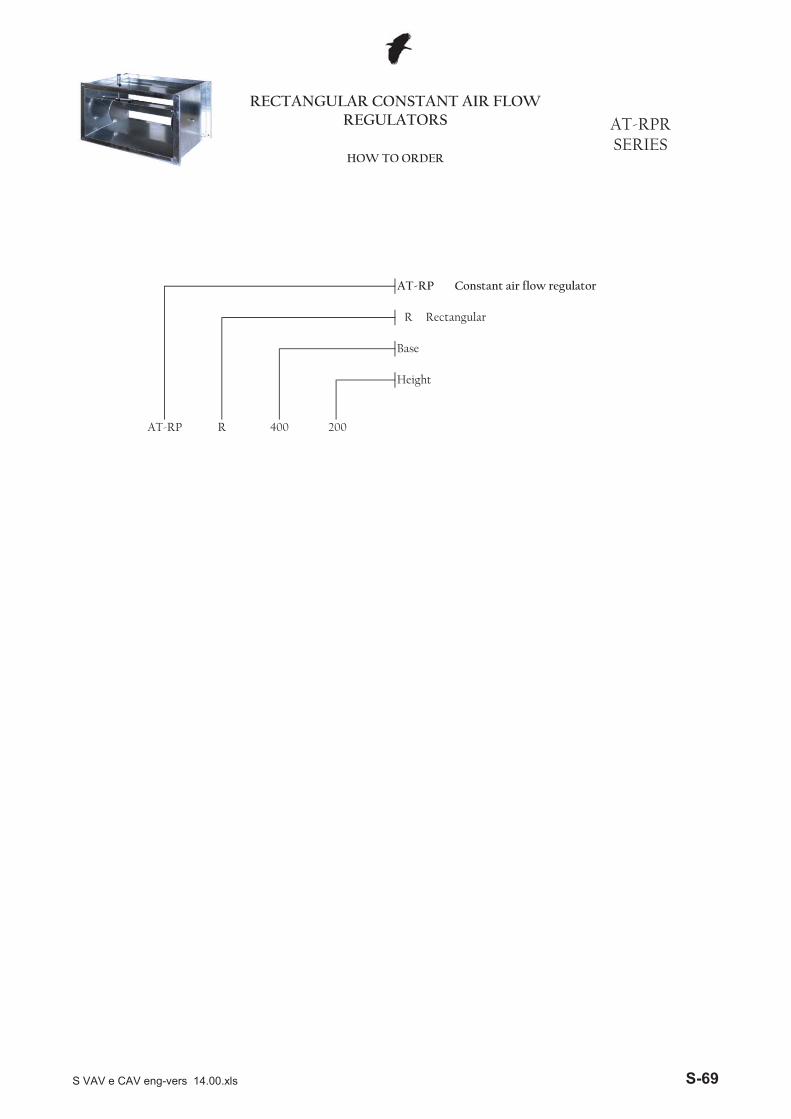
R Rectangular
Base
Height
AT-RP R 400 200
RECTANGULAR CONSTANT AIR FLOW REGULATORS AT-RPR
SERIESHOW TO ORDER
AT-RP Constant air flow regulator
S VAV e CAV eng-vers 14.00.xls S-69

S VAV e CAV eng-vers 14.00.xls S-70
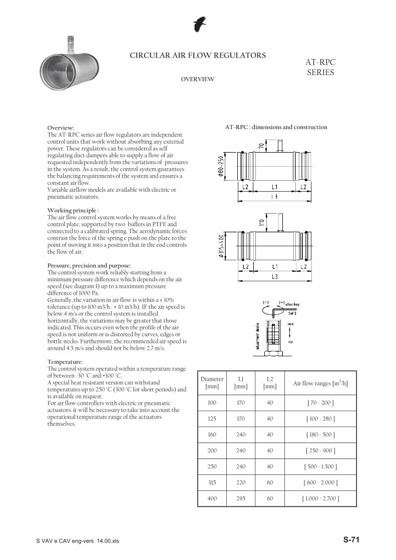
CIRCULAR AIR FLOW REGULATORSAT-RPC SERIES
OVERVIEW
Overview:The AT-RPC series air flow regulators are independent control units that work without absorbing any external power. These regulators can be considered as self regulating duct dampers able to supply a flow of air requested independently from the variations of pressures in the system. As a result, the control system guarantees the balancing requirements of the system and ensures a constant air flow. Variable airflow models are available with electric or pneumatic actuators.
Working principle :The air flow control system works by means of a free control plate, supported by two buffers in PTFE and connected to a calibrated spring. The aerodynamic forces contrast the force of the spring e push on the plate to the point of moving it into a position that in the end controls the flow of air.
Pressure, precision and purpose:The control system work reliably starting from a minimum pressure difference which depends on the air speed (see diagram 1) up to a maximum pressure
AT-RPC : dimensions and construction
400 295 60 [ 1.000 - 2.700 ]
250 240 40 [ 500 - 1.500 ]
315 220 60 [ 600 - 2.000 ]
160 240 40 [ 180 - 500 ]
200 240 40 [ 250 - 900 ]
100 170 40 [ 70 - 200 ]
125 170 40 [ 100 - 280 ]
Diameter [mm]
L1 [mm]
L2 [mm] Air flow ranges [m3/h]
p ( g ) p pdifference of 1000 Pa.Generally, the variation in air flow is within a ± 10% tolerance (up to 100 m3/h : ± 10 m3/h). IF the air speed is below 4 m/s or the control system is installed horizontally, the variations may be greater that those indicated. This occurs even when the profile of the air speed is not uniform or is distorted by curves, edges or bottle necks. Furthermore, the recommended air speed is around 4.5 m/s and should not be below 2.7 m/s.
Temperature:The control system operated within a temperature range of between -30 °C and +100 °C. A special heat resistant version can withstand temperatures up to 250 °C (300 °C for short periods) and is available on request.For air flow controllers with electric or pneumatic actuators. it will be necessary to take into account the operational temperature range of the actuators themselves.
S VAV e CAV eng-vers 14.00.xls S-71
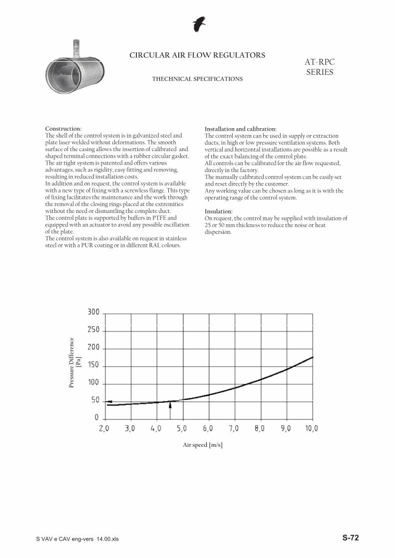
CIRCULAR AIR FLOW REGULATORSAT-RPC SERIES
THECHNICAL SPECIFICATIONS
Construction:The shell of the control system is in galvanized steel and plate laser welded without deformations. The smooth surface of the casing allows the insertion of calibrated and shaped terminal connections with a rubber circular gasket. The air tight system is patented and offers various advantages, such as rigidity, easy fitting and removing, resulting in reduced installation costs.In addition and on request, the control system is available with a new type of fixing with a screwless flange. This type of fixing facilitates the maintenance and the work through the removal of the closing rings placed at the extremities without the need or dismantling the complete duct. The control plate is supported by buffers in PTFE and equipped with an actuator to avoid any possible oscillation of the plate.The control system is also available on request in stainless steel or with a PUR coating or in different RAL colours.
Installation and calibration:The control system can be used in supply or extraction ducts, in high or low pressure ventilation systems. Both vertical and horizontal installations are possible as a result of the exact balancing of the control plate.All controls can be calibrated for the air flow requested, directly in the factory. The manually calibrated control system can be easily set and reset directly by the customer.Any working value can be chosen as long as it is with the operating range of the control system.
Insulation:On request, the control may be supplied with insulation of 25 or 50 mm thickness to reduce the noise or heat dispersion.
Air speed [m/s]
Pre
ssur
e D
iffe
renc
e[P
a]
S VAV e CAV eng-vers 14.00.xls S-72
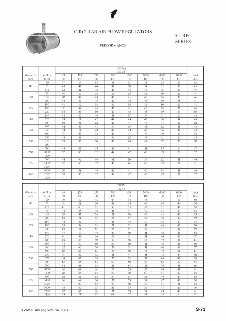
45 39 37 511400 57 55 52 48 4641 39 39 32 31 44
- - - - -
315600 48 46 44
47 46 39 38 521500 - - - -
41 41 35 34 471000 57 55 52 49
- - - -
250500 48 47 45 43
44 37 36 50900 - - - - -575 55 53 50 46 44
39 38 37 31 30 4347 47 40 39 52
200250 45 43 41
43 42 36 34 48500 57 55 52 49
38 38 32 31 43340 53 51 48 44
47 41 39 52
160180 44 43 41 39
42 36 34 48400 56 55 52 49 47270 53 51 47 44 43
38 37 37 31 30 4245 45 39 37 50
140140 43 42 40
41 40 34 32 46280 54 53 50 47
35 36 30 29 41190 51 49 46 42
45 39 38 51
125100 41 40 38 36
40 34 33 46200 54 52 49 47 45135 50 48 45 42 41
36 35 36 30 29 4144 44 38 37 49
10070 40 39 38
39 39 33 32 45125 52 51 48 45
33 33 28 27 3882 49 47 44 418040 37 37 35 33
Hz Hz Hz Hz Hz dBa1000 2000 4000 8000 LwA
mm m³/h Hz Hz Hzdiameter air flow 63 125 250 500
CIRCULAR AIR FLOW REGULATORSAT-RPC SERIES
PERFORMANCE
100 PaLw dB
61 55 53 6754 48 46 61
3800 73 71 67 64 622200 67 65 61 57 55
56 55 54 47 45 5960 59 53 51 65
4001000 58 59 57
55 54 47 46 602200 71 69 65 62
53 53 46 44 581400 66 64 60 57
60 53 52 65
315600 55 56 55 54
55 48 47 611500 70 68 65 62 601000 66 64 61 57 55
55 54 55 49 48 6058 58 52 50 64
250500 54 56 55
53 53 46 45 59900 68 66 63 60
51 51 45 44 56575 64 62 58 55
55 49 48 61
200250 51 52 52 51
51 44 43 57500 66 64 61 58 56340 62 60 56 53 51
50 50 51 46 45 5656 55 49 48 61
160180 48 50 50
51 51 44 43 57400 65 63 60 57
50 51 46 45 55270 61 59 56 53
53 47 46 59
140140 47 49 49 49
51 46 45 56280 63 61 58 55 54190 55 54 53 51 51
48 48 49 44 43 5454 54 48 47 59
125100 45 47 47
50 49 43 42 55200 63 61 58 55
47 49 44 43 53135 59 57 54 51
53 47 46 58
10070 43 45 46 46
49 44 44 54125 61 60 57 54 53
46 41 41 5082 51 51 50 49 48
Hz Hz dBa
8040 39 42 43 44 44
8000 LwAmm m³/h Hz Hz Hz Hz Hz Hz
Lw dBdiameter air flow 63 125 250 500 1000 2000 4000
- - - - -
250 Pa
47 46 39 37 523800 - - - -
41 40 33 31 462200 58 56 52 49
- - - -
4001000 50 48 45 422200 - - - - -
S VAV e CAV eng-vers 14.00.xls S-73
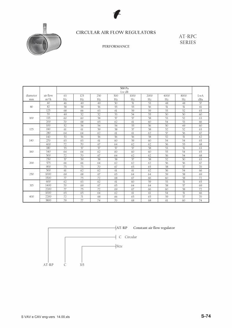
65 58 57 7062 56 56 67
900 75 73 70 67 65575 66 66 64 62 62
58 57 58 52 50 6362 62 56 54 68
200250 57 59 58
60 60 55 54 65500 72 70 67 64
57 58 53 51 63340 64 64 62 60
62 56 55 68
160180 55 57 57 57
60 54 54 65400 72 70 67 64 62270 63 63 61 60 59
56 56 58 52 51 6261 62 57 56 67
140140 53 56 56
57 58 52 52 63280 64 64 62 61
55 56 50 49 60190 61 61 59 58
60 54 53 66
125100 52 54 54 54
58 53 52 63200 70 68 65 62 61135 60 60 58 57 57
53 54 55 50 50 6059 59 53 52 65
10070 49 52 52
55 56 51 51 61125 68 66 63 61
51 53 48 48 5782 58 58 56 558040 46 49 49 50
Hz Hz Hz Hz Hz dBa1000 2000 4000 8000 LwA
mm m³/h Hz Hz Hzdiameter air flow 63 125 250 500
CIRCULAR AIR FLOW REGULATORSAT-RPC SERIES
PERFORMANCE
500 PaLw dB
Size
AT-RP C 315
60 74
AT-RP Constant air flow regulator
C Circular
703800 79 77 74 70 68 68 612200 72 71 68 66 65 65 59 57
62 61 61 54 51 6666 60 58 72
4001000 65 65 642200 77 75 72 69 67
64 64 58 57 6959 53 51 65
1400 70 69 67 65
58 72
315600 62 63 62 61 60
691500 77 75 72 68 67 66 601000 69 68 67 65 64 64 59 58
61 61 62 56 54 66250
500 61 62 62
S VAV e CAV eng-vers 14.00.xls S-74
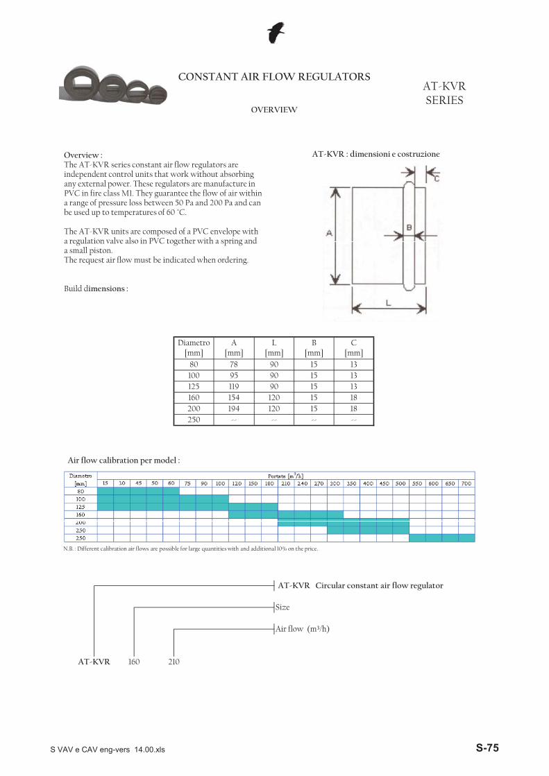
125 119 90 15 13160 154 120 15 18
80 78 90 15 13100 95 90 15 13
Diametro [mm]
A [mm]
L [mm]
B [mm]
C [mm]
CONSTANT AIR FLOW REGULATORSAT-KVR SERIES
OVERVIEW
AT-KVR : dimensioni e costruzioneOverview :The AT-KVR series constant air flow regulators are independent control units that work without absorbing any external power. These regulators are manufacture in PVC in fire class M1. They guarantee the flow of air within a range of pressure loss between 50 Pa and 200 Pa and can be used up to temperatures of 60 °C.
The AT-KVR units are composed of a PVC envelope with a regulation valve also in PVC together with a spring and a small piston.The request air flow must be indicated when ordering.
Build dimensions :
AT-KVR Circular constant air flow regulator
Size
Air flow (m³/h)
AT-KVR 160 210
200 194 120 15 18250 -- -- -- --
160 154 120 15 18
N.B. : Different calibration air flows are possible for large quantities with and additional 10% on the price.
Air flow calibration per model :
S VAV e CAV eng-vers 14.00.xls S-75
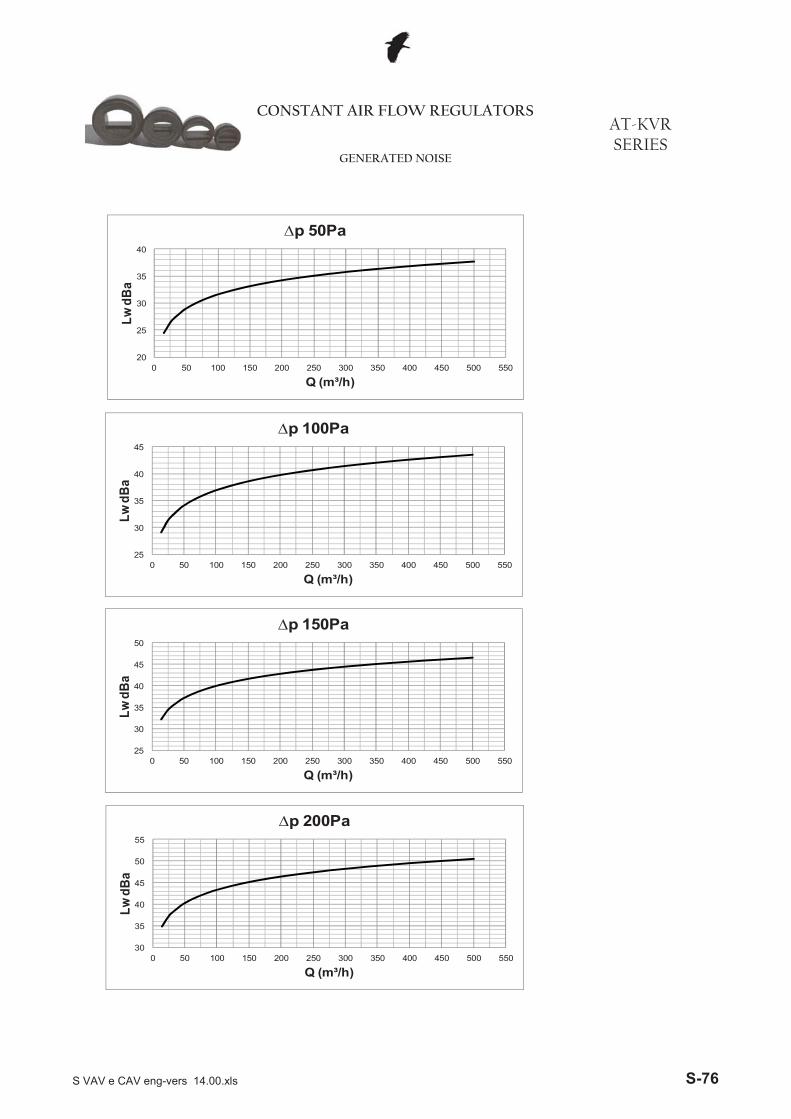
CONSTANT AIR FLOW REGULATORSAT-KVR SERIES
GENERATED NOISE
25
30
35
40
45
0 50 100 150 200 250 300 350 400 450 500 550
Lw d
Ba
Q ( ³/h)
�p 100Pa
20
25
30
35
40
0 50 100 150 200 250 300 350 400 450 500 550
Lw d
Ba
Q (m³/h)
�p 50Pa
30
35
40
45
50
55
0 50 100 150 200 250 300 350 400 450 500 550
Lw d
Ba
Q (m³/h)
�p 200Pa
25
30
35
40
45
50
0 50 100 150 200 250 300 350 400 450 500 550
Lw d
Ba
Q (m³/h)
�p 150Pa
Q (m³/h)
S VAV e CAV eng-vers 14.00.xls S-76
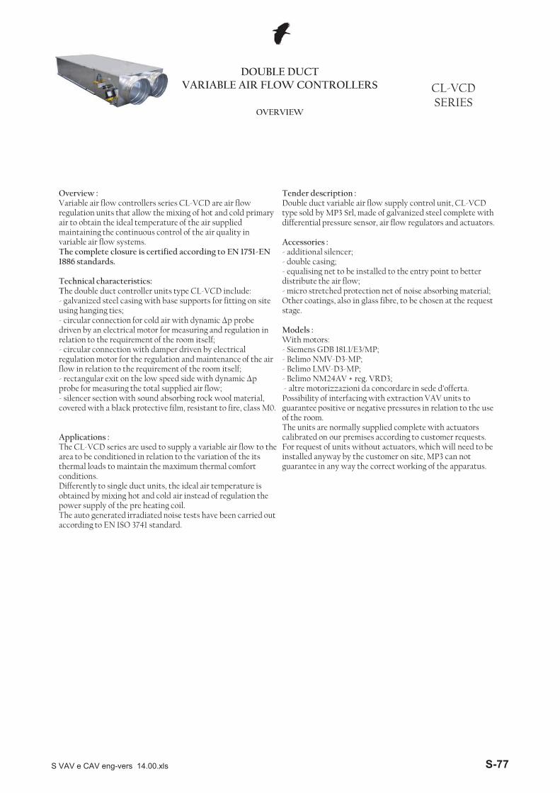
DOUBLE DUCT VARIABLE AIR FLOW CONTROLLERS CL-VCD
SERIESOVERVIEW
Overview :Variable air flow controllers series CL-VCD are air flow regulation units that allow the mixing of hot and cold primary air to obtain the ideal temperature of the air supplied maintaining the continuous control of the air quality in variable air flow systems.The complete closure is certified according to EN 1751-EN 1886 standards.
Technical characteristics:The double duct controller units type CL-VCD include:- galvanized steel casing with base supports for fitting on site using hanging ties;- circular connection for cold air with dynamic �p probe driven by an electrical motor for measuring and regulation in relation to the requirement of the room itself;- circular connection with damper driven by electrical regulation motor for the regulation and maintenance of the air flow in relation to the requirement of the room itself;- rectangular exit on the low speed side with dynamic �p probe for measuring the total supplied air flow;- silencer section with sound absorbing rock wool material, covered with a black protective film resistant to fire class M0
Tender description : Double duct variable air flow supply control unit, CL-VCD type sold by MP3 Srl, made of galvanized steel complete with differential pressure sensor, air flow regulators and actuators.
Accessories : - additional silencer;- double casing;- equalising net to be installed to the entry point to better distribute the air flow;- micro stretched protection net of noise absorbing material; Other coatings, also in glass fibre, to be chosen at the request stage.
Models :With motors:- Siemens GDB 181.1/E3/MP;- Belimo NMV-D3-MP; - Belimo LMV-D3-MP; - Belimo NM24AV + reg. VRD3;- altre motorizzazioni da concordare in sede d’offerta.Possibility of interfacing with extraction VAV units to guarantee positive or negative pressures in relation to the usecovered with a black protective film, resistant to fire, class M0.
Applications : The CL-VCD series are used to supply a variable air flow to the area to be conditioned in relation to the variation of the its thermal loads to maintain the maximum thermal comfort conditions.Differently to single duct units, the ideal air temperature is obtained by mixing hot and cold air instead of regulation the power supply of the pre heating coil.The auto generated irradiated noise tests have been carried out according to EN ISO 3741 standard.
guarantee positive or negative pressures in relation to the use of the room.The units are normally supplied complete with actuators calibrated on our premises according to customer requests. For request of units without actuators, which will need to be installed anyway by the customer on site, MP3 can not guarantee in any way the correct working of the apparatus.
S VAV e CAV eng-vers 14.00.xls S-77
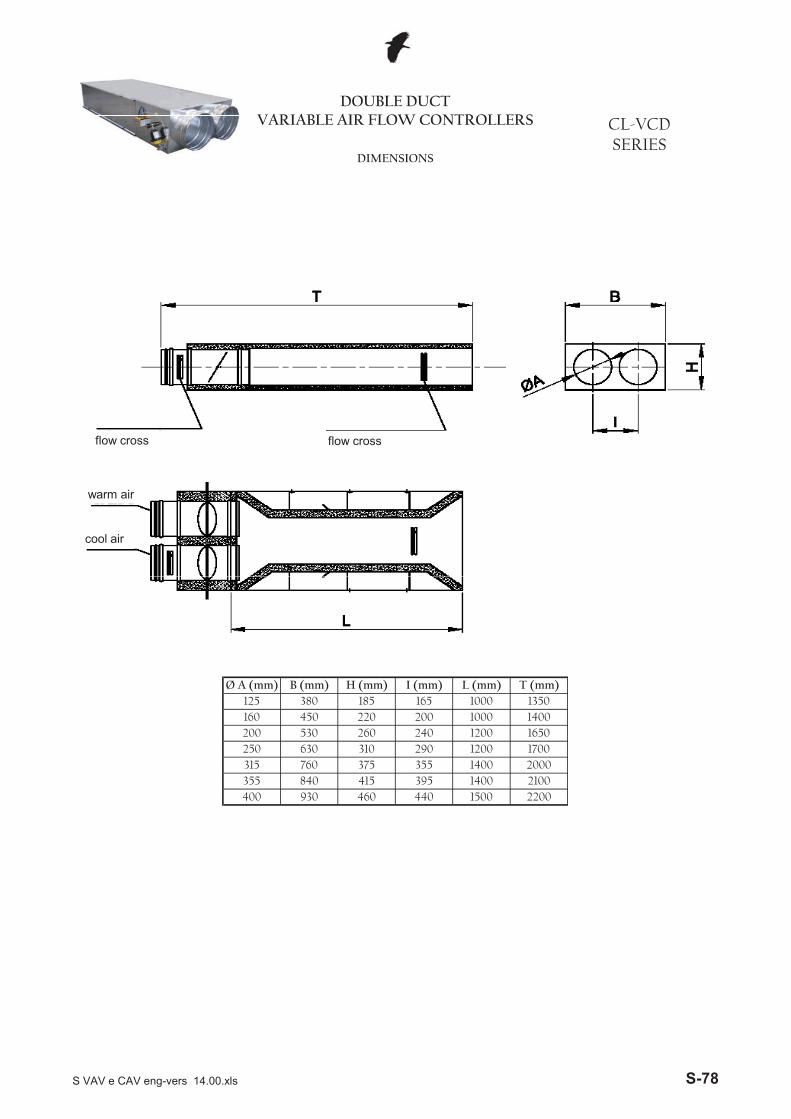
DOUBLE DUCT VARIABLE AIR FLOW CONTROLLERS CL-VCD
SERIESDIMENSIONS
flow cross flow cross
warm air
cool air
450 1400530 260 1200 1650
220 1000
315 760 375 1400
200630
20002100
930 460
1700
2200
3551200
1500395440
250
200240290310
400
380 185 1000I (mm)
165
355 840 415 1400
1601350
Ø A (mm) B (mm) H (mm) L (mm) T (mm)125
S VAV e CAV eng-vers 14.00.xls S-78
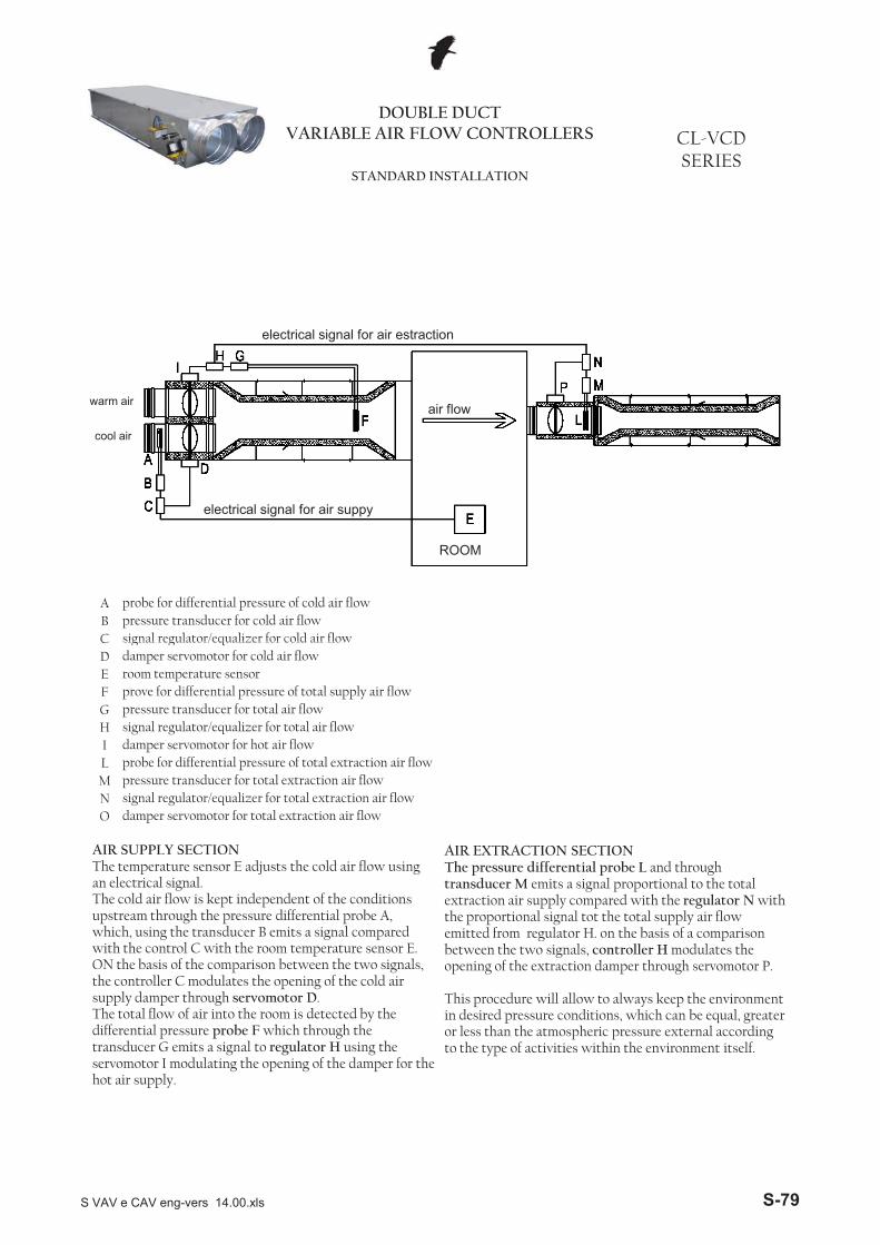
A probe for differential pressure of cold air flowB pressure transducer for cold air flowC signal regulator/equalizer for cold air flow
DOUBLE DUCT VARIABLE AIR FLOW CONTROLLERS CL-VCD
SERIESSTANDARD INSTALLATION
electrical signal for air suppy
electrical signal for air estraction
warm air
cool air
ROOM
air flow
C signal regulator/equalizer for cold air flowD damper servomotor for cold air flowE room temperature sensorF prove for differential pressure of total supply air flowG pressure transducer for total air flow H signal regulator/equalizer for total air flowI damper servomotor for hot air flow L probe for differential pressure of total extraction air flow M pressure transducer for total extraction air flowN signal regulator/equalizer for total extraction air flowO damper servomotor for total extraction air flow
AIR SUPPLY SECTIONThe temperature sensor E adjusts the cold air flow using an electrical signal.The cold air flow is kept independent of the conditions upstream through the pressure differential probe A, which, using the transducer B emits a signal compared with the control C with the room temperature sensor E. ON the basis of the comparison between the two signals, the controller C modulates the opening of the cold air supply damper through servomotor D.The total flow of air into the room is detected by the differential pressure probe F which through the transducer G emits a signal to regulator H using the servomotor I modulating the opening of the damper for the hot air supply.
AIR EXTRACTION SECTIONThe pressure differential probe L and through transducer M emits a signal proportional to the total extraction air supply compared with the regulator N with the proportional signal tot the total supply air flow emitted from regulator H. on the basis of a comparison between the two signals, controller H modulates the opening of the extraction damper through servomotor P.
This procedure will allow to always keep the environment in desired pressure conditions, which can be equal, greater or less than the atmospheric pressure external according to the type of activities within the environment itself.
S VAV e CAV eng-vers 14.00.xls S-79
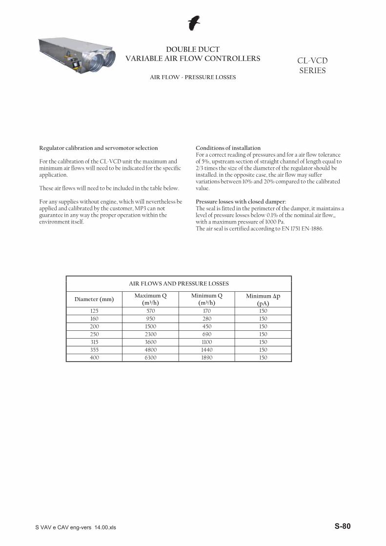
DOUBLE DUCT VARIABLE AIR FLOW CONTROLLERS CL-VCD
SERIESAIR FLOW - PRESSURE LOSSES
A A
Regulator calibration and servomotor selection
For the calibration of the CL-VCD unit the maximum and minimum air flows will need to be indicated for the specific application.
These air flows will need to be included in the table below.
For any supplies without engine, which will nevertheless be applied and calibrated by the customer, MP3 can not guarantee in any way the proper operation within the environment itself.
Conditions of installationFor a correct reading of pressures and for a air flow tolerance of 5%, upstream section of straight channel of length equal to 2/3 times the size of the diameter of the regulator should be installed. in the opposite case, the air flow may suffer variations between 10% and 20% compared to the calibrated value.
Pressure losses with closed damper:The seal is fitted in the perimeter of the damper, it maintains a level of pressure losses below 0.1% of the nominal air flow,, with a maximum pressure of 1000 Pa.The air seal is certified according to EN 1751 EN-1886.
125 570 170 150160 950 280 150
AIR FLOWS AND PRESSURE LOSSES
Diameter (mm)Maximum Q
(m³/h)Minimum Q
(m³/h)Minimum �p
(pA)
1440 150
150250 2300 690 150
1500 450200
400 6300 1890 150
315 3600 1100 150355 4800
S VAV e CAV eng-vers 14.00.xls S-80
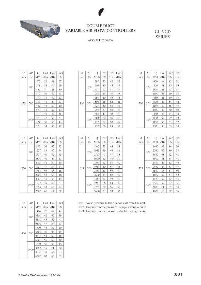
Ø �P Q Lw1 Lw2 Lw3 Ø �P Q Lw1 Lw2 Lw3 Ø �P Q Lw1 Lw2 Lw3mm Pa M³/h dBa dBa dBa mm Pa M³/h dBa dBa dBa mm Pa M³/h dBa dBa dBa
170 32 38 27 280 35 42 32 450 34 42 32
303 35 40 29 503 40 45 35 800 38 45 35
437 37 41 30 727 43 47 37 1150 41 47 37
570 39 42 31 950 45 49 38 1500 43 49 38
170 38 42 32 280 40 46 35 450 41 49 38
303 43 47 37 503 46 52 41 800 47 54 44
437 46 50 40 727 50 55 44 1150 50 58 47
570 49 52 42 950 53 58 47 1500 53 60 50
170 40 46 36 280 44 50 40 450 46 54 43
303 47 50 41 503 50 56 46 800 52 59 48
437 51 53 44 727 54 60 49 1150 55 63 52
570 54 55 47 950 56 63 52 1500 58 65 54
Ø �P Q Lw1 Lw2 Lw3 Ø �P Q Lw1 Lw2 Lw3 Ø �P Q Lw1 Lw2 Lw3mm Pa M³/h dBa dBa dBa mm Pa M³/h dBa dBa dBa mm Pa M³/h dBa dBa dBa
690 36 42 32 1100 37 44 34 1440 39 44 34
500 500 500
1000 1000 1000
DOUBLE DUCT VARIABLE AIR FLOW CONTROLLERS CL-VCD
SERIESACOUSTIC DATA
125
200
160
200
200
200
690 36 42 32 1100 37 44 34 1440 39 44 34
1227 38 45 34 1933 39 46 36 2560 45 49 38
1763 40 46 36 2767 41 47 38 3680 48 52 41
2300 41 47 37 3600 42 48 39 4800 51 54 43
690 43 50 39 1100 47 54 42 1440 47 52 42
1227 47 54 43 1933 50 57 45 2560 53 57 47
1763 50 56 46 2767 52 59 48 3680 56 61 50
2300 52 58 48 3600 54 60 49 4800 59 63 52
690 49 57 45 1100 52 59 48 1440 52 57 46
1227 55 62 51 1933 56 63 52 2560 57 62 51
1763 58 65 54 2767 59 66 55 3680 61 65 54
2300 61 67 57 3600 61 68 57 4800 63 67 56
Ø �P Q Lw1 Lw2 Lw3 Lw1= Noise pressure in the duct on exit from the unitmm Pa M³/h dBa dBa dBa Lw2= Irradiated noise pressure - simple casing version
1890 37 44 34 Lw3= Irradiated noise pressure - double casing version 3360 42 49 39
4830 45 52 41
6300 47 54 43
1890 46 52 40
3360 51 57 45
4830 54 60 48
6300 56 62 50
1890 51 57 45
3360 55 61 50
4830 58 64 53
6300 60 66 55
355
200
500 500 500
1000 1000 1000
315
200
400
200
500
1000
250
200
S VAV e CAV eng-vers 14.00.xls S-81
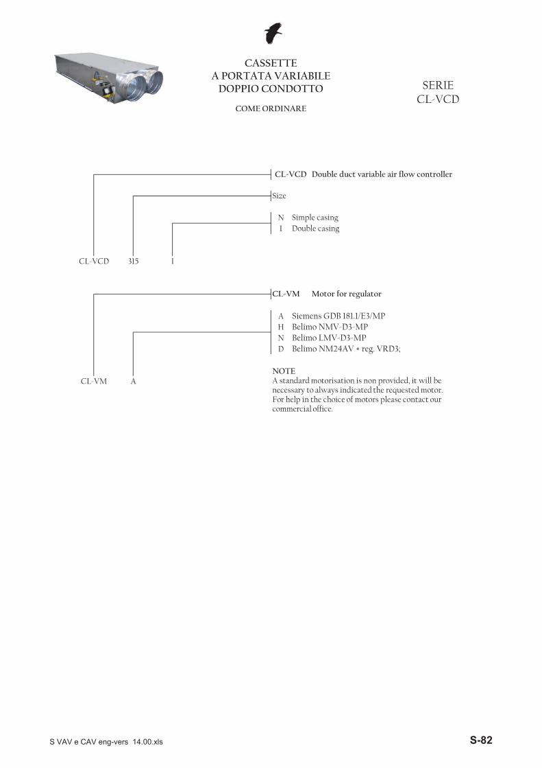
NI
AHND
Belimo LMV-D3-MPBelimo NM24AV + reg. VRD3;
CL-VM A
CL-VM Motor for regulator
Siemens GDB 181.1/E3/MPBelimo NMV-D3-MP
Size
Simple casingDouble casing
CL-VCD 315 I
CASSETTEA PORTATA VARIABILE
DOPPIO CONDOTTO SERIECL-VCD
COME ORDINARE
CL-VCD Double duct variable air flow controller
NOTEA standard motorisation is non provided, it will be necessary to always indicated the requested motor.
h l h h f lFor help in the choice of motors please contact our commercial office.
S VAV e CAV eng-vers 14.00.xls S-82

![Occupational asthma: Pathogenesis - UFPR...eosinophilic bronchitis) [1]. Occupational asthma is a disease characterized by variable airflow limitation, airway hyperresponsiveness,](https://img.pdfslide.us/doc/110x75/5e5df342484c5e16a546eb09/occupational-asthma-pathogenesis-eosinophilic-bronchitis-1-occupational.jpg)