Embed Size (px)
Citation preview
Steam boilers
Heat pumps
Technical manual


Technical manualHeat pumps

The Viessmann Group
D-35107 Allendorf (Eder)
Telephone +49 (0)6452 70-0
Fax +49 (0)6452 70-2780
www.viessmann.com
9440 134 GB 03/2012
Subject to technical modifications

Technical manualHeat pumps

Table of contents

6/7
11 Foreword
12 Introduction
12 How to use this manual
14 A Principles of heat pump technology
16 A.1 History of heat pump development
18 A.2 Physical principles
19 A.2.1 Condensing and evaporating
19 A.2.2 Refrigerant circuit
21 A.2.3 Coefficient of performance (COP)
22 A.2.4 Seasonal performance factor (SPF)
24 A.3 Main components
25 A.3.1 Compressor
28 A.3.2 Expansion valve
29 A.3.3 Heat exchanger
31 A.3.4 Refrigerant
32 A.4 Primary source potentials
33 A.4.1 Ground as heat source
37 A.4.2 Water as heat source
37 A.4.3 Outdoor air as heat source
38 A.4.4 Availability and efficiency – assessment of the primary sources
38 A.4.5 Waste heat as heat source
39 A.4.6 Absorber with solar backup
40 A.4.7 Phase change as "storage" on the primary side
42 A.5 Alternative types of heat pump
43 A.5.1 Compression heat pumps with internal combustion engine
43 A.5.2 Absorption heat pumps
45 A.5.3 Adsorption heat pumps
Table of contents

46 B General conditions
48 B.1 "Electrical power" as the driving energy
49 B.1.1 Power mix in Germany
51 B.1.2 Security of supply
53 B.1.3 Smart metering
54 B.1.4 Heat pumps and photovoltaics
55 B.1.5 Competition for electric power
56 B.2 Statutory framework conditions
57 B.2.1 Heat pumps in the EnEV
59 B.2.2 Heat pumps in the Renewable Energies Heat Act [EEWärmeG]
59 B.2.3 European framework directives
60 B.3 Economic considerations
62 C Engineering and sizing the primary source
64 C.1 Brine/water heat pumps
65 C.1.1 Sizing the heat source
69 C.1.2 Heat transfer medium
70 C.1.3 Flow rate and pressure drop in the brine circuit
72 C.2 Water/water heat pumps
73 C.2.1 Groundwater
75 C.2.2 Coolant
76 C.3 Air/water heat pumps
77 C.3.1 Air/water heat pumps with unregulated compressor
77 C.3.2 Sizing/engineering
79 C.3.3 Acoustic engineering
82 C.3.4 Air routing for internally sited air/water heat pumps
84 D System engineering
86 D.1 Operating modes
87 D.1.1 Mono mode operation
87 D.1.2 Dual mode operation
89 D.1.3 Cascade systems
90 D.1.4 Combination with renewables
92 D.2 Secondary circuit
93 D.2.1 DHW heating
106 D.2.2 Heating operation
111 D.2.3 Cooling
116 D.3 Output calculation and engineering aids
117 D.3.1 Determining the heat pump output
118 D.3.2 Sizing aids for heat pump systems
Table of contents

8/9
122 Appendix
124 The path to an efficient heat pump system
130 Information on inspection and optimisation
132 Keyword index
136 The company
136 Individual solutions with efficient systems
138 Futureproof heating technology for all requirements
140 Viessmann – climate of innovation
142 Production


10/11
Foreword
Climate protection and the provision of
futureproof affordable energy are two of
the most serious challenges of our time.
In order to prevent the atmosphere from
heating up further, emissions of greenhouse
gases, among them particularly CO2, must be
minimised. This can only be achieved through
a significant reduction in the consumption of
fossil fuels. This reduction is unavoidable –
quite apart from efforts to reduce the effects
of climate change – because these resources
are finite. Although supplies will still be
available for the foreseeable future, prices
will continue to rise. Consequently, improving
energy efficiency and extending the scope of
renewables are key areas of interest.
Politicians have determined ambitious goals
for both climate protection and saving energy.
The heating sector, as the largest consumer,
can make a substantial contribution to these
aims. It is, therefore, essential that existing
outdated and inefficient heating equipment is
replaced as soon as possible. The technology
required for this is available right now.
The comprehensive range from Viessmann
not only offers highly efficient condensing
technology for oil and gas, but also biomass
boilers, solar thermal systems and heat
pumps for any application area.
Over the past few years, heat pumps
have established their place in the heating
technology sector. Their share of the
new build market is now equal to that of
gas condensing systems. However, in
modernisation projects, too, heat pumps are
gaining in importance. Correctly sized and
installed, they can provide heat economically
in almost any building and for almost any
requirement, whilst treating resources as
carefully as possible.
Viessmann expects that in the years to come,
heat pumps will play an even greater role in
our industry. Firstly, product development
continues apace. Large heat pumps can
cover additional types of buildings and
commercial applications. In the lower output
ranges, there is a clear trend towards more
compact solutions that make engineering
and implementation significantly easier. Our
trade partners can be sure that everything
fits together as it should. Secondly, an
increasing number of heating contractors feel
more confident with this technology that is
still rather unfamiliar to many. I'm glad that,
with this technical manual, we can support
our trade partners to propel them to even
greater success.
Dr Martin Viessmann

Introduction

12/13
How to use this manual
Compared with conventional heat generators,
heat pumps are complex machines that
require detailed explanation in order to be
properly understood, not only by end users,
but also by heating contractors and design
engineers alike. The basic functions of a boiler
operating with oil, gas or biomass, are fairly
comprehensible. With heat pumps, however,
many fail to overcome the paradox that a
"cold" primary source – such as the ground,
groundwater or ambient air – can provide
heat that is useful for heating the interior of
a building. This manual, therefore, dedicates
much of its attention to the explanation of
the working principles of this fascinating
technology.
The following illustrations and descriptions
aim to raise the level of understanding of
the workings of the most important heat
pump system components. Consequently,
the diagrams illustrate working principles,
and should not be seen as complete
installation instructions. These are found in
the product documentation, the appliance-
specific technical guides and the Viessmann
scheme browser.
Information on practical implementation is
only represented in this manual if there are
specific considerations that must be taken
into account when installing heat pump
systems.
All other electronic engineering aids
mentioned in the following chapters, such as
the engineering programs, for example, are
available to Viessmann trade partners from
their sales engineer contacts; alternatively,
they can be downloaded from the internet.
Introduction
This manual provides important information concerning the engineering, layout and operation of heat pump systems. It is intended to be a work of reference as much as a training manual and consultation guide.

14/15
Heat pumps are able to raise this energy to a
useful temperature level.
This chapter explains the principles behind
this technology and also describes the
essential components of a heat pump.
Generally, we perceive warmth as a feeling
rather than something quantifiable. We sense
that a sunny summer's day, or a cosily heated
house in winter is warm and a winter's day or
an unheated house is cold.
Scientifically speaking, however, down to
absolute zero (0 K = -273.15 °C) matter still
contains heating energy.
16 A.1 History of heat pump development
18 A.2 Physical principles
19 A.2.1 Condensing and evaporating
19 A.2.2 Refrigerant circuit
21 A.2.3 Coefficient of performance (COP)
22 A.2.4 Seasonal performance factor (SPF)
24 A.3 Main components
25 A.3.1 Compressor
28 A.3.2 Expansion valve
29 A.3.3 Heat exchanger
31 A.3.4 Refrigerant
32 A.4 Primary source potentials
33 A.4.1 Ground as heat source
37 A.4.2 Water as heat source
37 A.4.3 Outdoor air as heat source
38 A.4.4 Availability and efficiency – assessment of the primary sources
38 A.4.5 Waste heat as heat source
39 A.4.6 Absorber with solar backup
40 A.4.7 Phase change as "storage" on the primary side
42 A.5 Alternative types of heat pump
43 A.5.1 Compression heat pumps with internal combustion engine
43 A.5.2 Absorption heat pumps
45 A.5.3 Adsorption heat pumps
A Principles of heat pump technology
Heat pumps can exploit the latent heat in the environment, bringing it up to useful temperatures. Their potential is almost limitless.
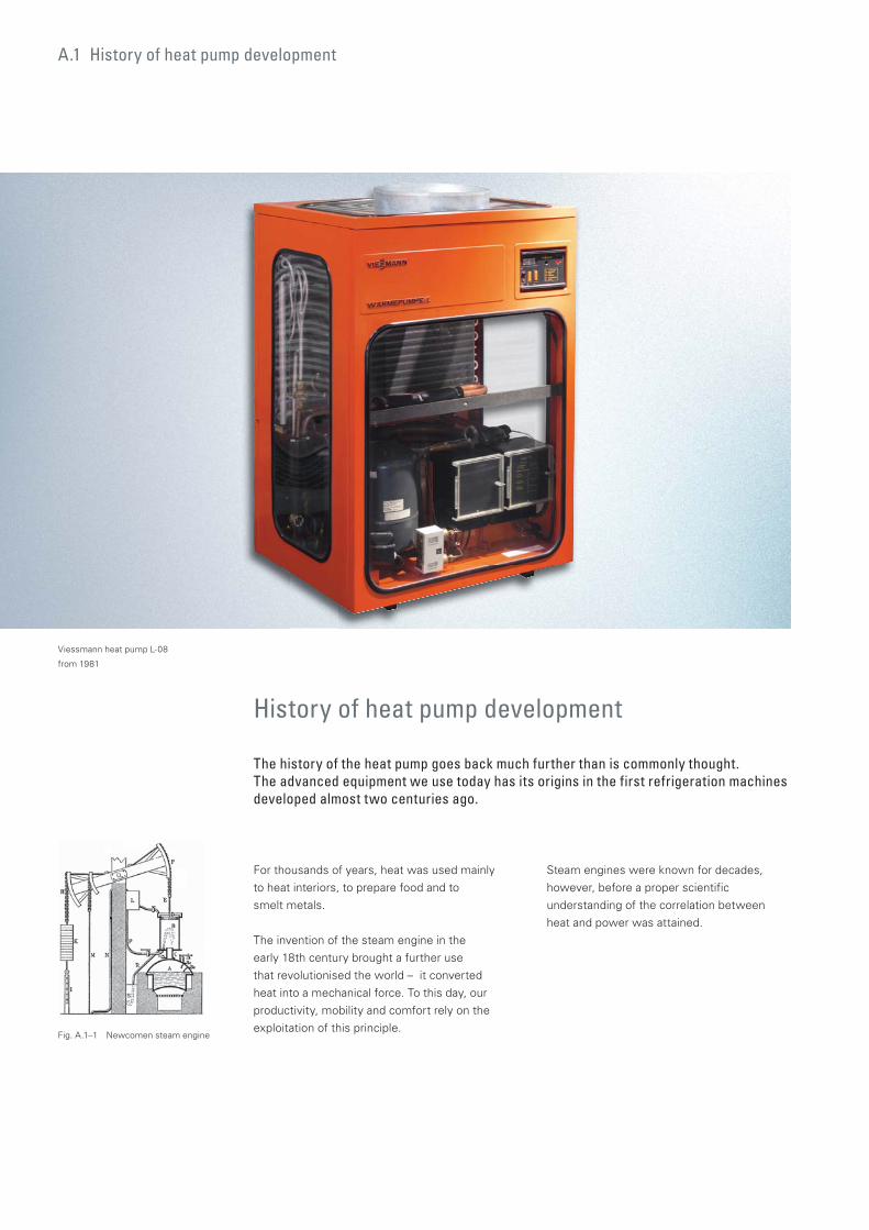
For thousands of years, heat was used mainly
to heat interiors, to prepare food and to
smelt metals.
The invention of the steam engine in the
early 18th century brought a further use
that revolutionised the world – it converted
heat into a mechanical force. To this day, our
productivity, mobility and comfort rely on the
exploitation of this principle.
History of heat pump development
The history of the heat pump goes back much further than is commonly thought. The advanced equipment we use today has its origins in the first refrigeration machines developed almost two centuries ago.
A.1 History of heat pump development
Fig. A.1–1 Newcomen steam engine
Steam engines were known for decades,
however, before a proper scientific
understanding of the correlation between
heat and power was attained.
Viessmann heat pump L-08
from 1981
16/17
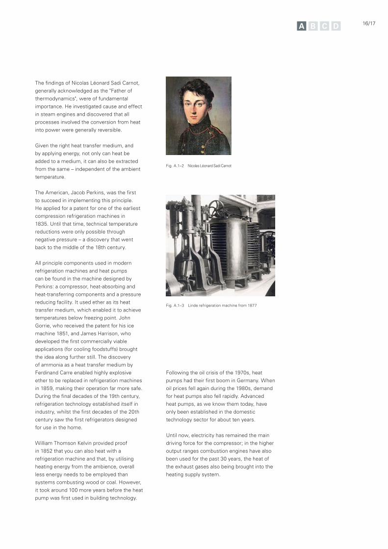
The findings of Nicolas Léonard Sadi Carnot,
generally acknowledged as the "Father of
thermodynamics", were of fundamental
importance. He investigated cause and effect
in steam engines and discovered that all
processes involved the conversion from heat
into power were generally reversible.
Given the right heat transfer medium, and
by applying energy, not only can heat be
added to a medium, it can also be extracted
from the same – independent of the ambient
temperature.
The American, Jacob Perkins, was the first
to succeed in implementing this principle.
He applied for a patent for one of the earliest
compression refrigeration machines in
1835. Until that time, technical temperature
reductions were only possible through
negative pressure – a discovery that went
back to the middle of the 18th century.
All principle components used in modern
refrigeration machines and heat pumps
can be found in the machine designed by
Perkins: a compressor, heat-absorbing and
heat-transferring components and a pressure
reducing facility. It used ether as its heat
transfer medium, which enabled it to achieve
temperatures below freezing point. John
Gorrie, who received the patent for his ice
machine 1851, and James Harrison, who
developed the first commercially viable
applications (for cooling foodstuffs) brought
the idea along further still. The discovery
of ammonia as a heat transfer medium by
Ferdinand Carre enabled highly explosive
ether to be replaced in refrigeration machines
in 1859, making their operation far more safe.
During the final decades of the 19th century,
refrigeration technology established itself in
industry, whilst the first decades of the 20th
century saw the first refrigerators designed
for use in the home.
William Thomson Kelvin provided proof
in 1852 that you can also heat with a
refrigeration machine and that, by utilising
heating energy from the ambience, overall
less energy needs to be employed than
systems combusting wood or coal. However,
it took around 100 more years before the heat
pump was first used in building technology.
Fig. A.1–2 Nicolas Léonard Sadi Carnot
Fig. A.1–3 Linde refrigeration machine from 1877
Following the oil crisis of the 1970s, heat
pumps had their first boom in Germany. When
oil prices fell again during the 1980s, demand
for heat pumps also fell rapidly. Advanced
heat pumps, as we know them today, have
only been established in the domestic
technology sector for about ten years.
Until now, electricity has remained the main
driving force for the compressor; in the higher
output ranges combustion engines have also
been used for the past 30 years, the heat of
the exhaust gases also being brought into the
heating supply system.

A.2 Physical principles
Physical principles
Heating technology in applied situations does not generally have to concern itself with the physical principles of heat generators.
A vessel filled with boiling water, for example,
will cool down under normal ambient
temperatures until it has reached the same
temperature as the ambient air. Heat pumps
cannot change this law of physics. Instead,
they use a different effect, i.e. energy that is
brought into a substance does not only lead
to an increase in temperature, but also to a
change in its aggregated state.
For example, if additional energy is supplied to
the vessel containing boiling water, then it will
evaporate without increasing its temperature.
The amount of energy involved in this change
of state is the "secret" with which the heat
pump yields energy at a useful temperature
level from a "cold" heat source.
In most cases it is sufficient to observe the
technical rules in order to ensure reliable
engineering, installation and commissioning.
However, it is useful to take a look at the
physical correlations, in order to better
understand the conditions under which a heat
generator, particularly a heat pump, can be
best used.
Heat is one form of the inner energy of
matter, or in thermodynamic terms, of a
system. A heat flux is created where there is
the possibility of this energy transferring to
another substance (a different system). This
always flows towards the lower temperature
and never the other way round, i.e. this flow is
non-reversible.
18/19
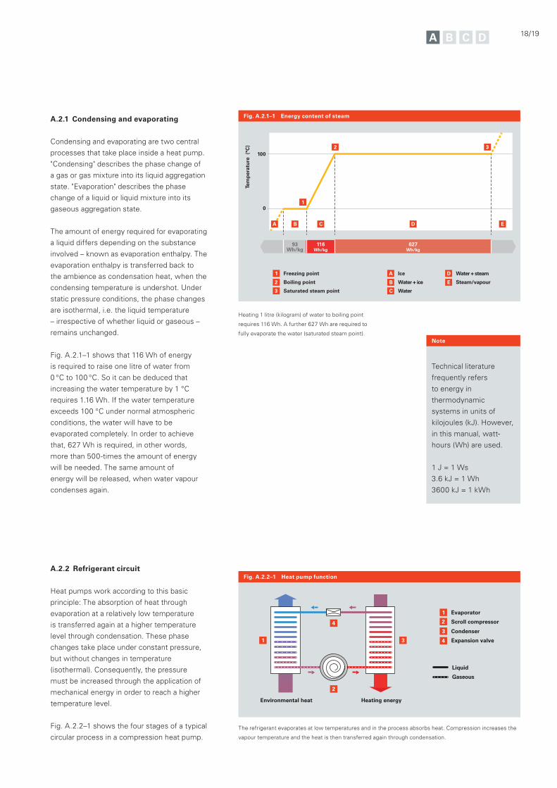
A.2.1 Condensing and evaporating
Condensing and evaporating are two central
processes that take place inside a heat pump.
"Condensing" describes the phase change of
a gas or gas mixture into its liquid aggregation
state. "Evaporation" describes the phase
change of a liquid or liquid mixture into its
gaseous aggregation state.
The amount of energy required for evaporating
a liquid differs depending on the substance
involved – known as evaporation enthalpy. The
evaporation enthalpy is transferred back to
the ambience as condensation heat, when the
condensing temperature is undershot. Under
static pressure conditions, the phase changes
are isothermal, i.e. the liquid temperature
– irrespective of whether liquid or gaseous –
remains unchanged.
Fig. A.2.1–1 shows that 116 Wh of energy
is required to raise one litre of water from
0 °C to 100 °C. So it can be deduced that
increasing the water temperature by 1 °C
requires 1.16 Wh. If the water temperature
exceeds 100 °C under normal atmospheric
conditions, the water will have to be
evaporated completely. In order to achieve
that, 627 Wh is required, in other words,
more than 500-times the amount of energy
will be needed. The same amount of
energy will be released, when water vapour
condenses again.
A.2.2 Refrigerant circuit
Heat pumps work according to this basic
principle: The absorption of heat through
evaporation at a relatively low temperature
is transferred again at a higher temperature
level through condensation. These phase
changes take place under constant pressure,
but without changes in temperature
(isothermal). Consequently, the pressure
must be increased through the application of
mechanical energy in order to reach a higher
temperature level.
Fig. A.2.2–1 shows the four stages of a typical
circular process in a compression heat pump.
Heating 1 litre (kilogram) of water to boiling point
requires 116 Wh. A further 627 Wh are required to
fully evaporate the water (saturated steam point).
Tem
per
atu
re (
°C)
116Wh/kg
627Wh/kg
93Wh/kg
0
1003
EDCB
2
1
1 Freezing point
Boiling point
Saturated steam point
2
3
A Ice
Water + ice
Water
B
C
D Water + steam
Steam/vapourE
A
Fig. A.2.1–1 Energy content of steam
Technical literature
frequently refers
to energy in
thermodynamic
systems in units of
kilojoules (kJ). However,
in this manual, watt-
hours (Wh) are used.
1 J = 1 Ws
3.6 kJ = 1 Wh
3600 kJ = 1 kWh
Note
2
1
1 3
Evaporator
Scroll compressor
Condenser
Expansion valve4
3
Liquid
Gaseous
4
Heating energyEnvironmental heat
2
Fig. A.2.2–1 Heat pump function
The refrigerant evaporates at low temperatures and in the process absorbs heat. Compression increases the
vapour temperature and the heat is then transferred again through condensation.
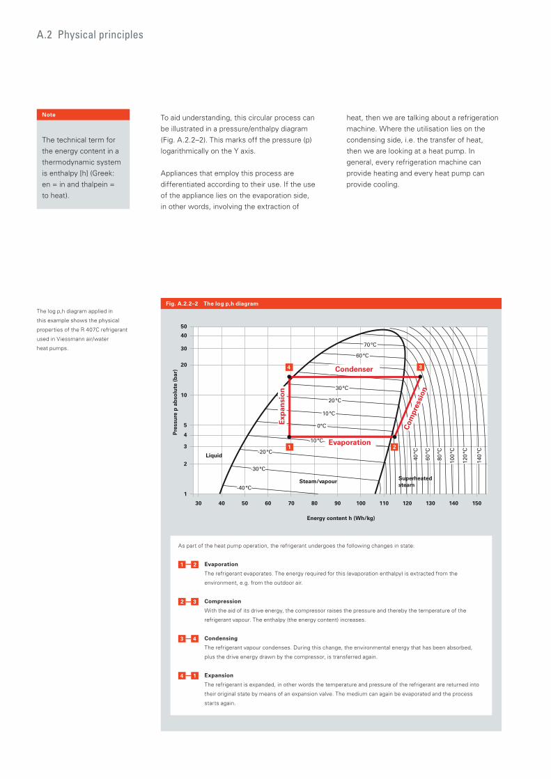
To aid understanding, this circular process can
be illustrated in a pressure/enthalpy diagram
(Fig. A.2.2–2). This marks off the pressure (p)
logarithmically on the Y axis.
Appliances that employ this process are
differentiated according to their use. If the use
of the appliance lies on the evaporation side,
in other words, involving the extraction of
A.2 Physical principles
40
50
30
20
10
5
4
3
2
1
Energy content h (Wh/kg)
Pre
ssu
re p
ab
solu
te (
bar
)
100 110 120 130 140 15080 907050 604030
0°C
10°C
-10°C
20°C
-20°C
30°C
-30°C
-40°C
70°C
60°C
80
°C
60
°C
40
°C
100
°C
120
°C
140
°C
Evaporation
Condenser
Exp
ansi
on
Com
pres
sion
Superheated steam
Steam/vapour
Liquid
1 2
34
Fig. A.2.2–2 The log p,h diagramThe log p,h diagram applied in
this example shows the physical
properties of the R 407C refrigerant
used in Viessmann air/water
heat pumps.
As part of the heat pump operation, the refrigerant undergoes the following changes in state:
Evaporation
The refrigerant evaporates. The energy required for this (evaporation enthalpy) is extracted from the
environment, e.g. from the outdoor air.
Compression
With the aid of its drive energy, the compressor raises the pressure and thereby the temperature of the
refrigerant vapour. The enthalpy (the energy content) increases.
Condensing
The refrigerant vapour condenses. During this change, the environmental energy that has been absorbed,
plus the drive energy drawn by the compressor, is transferred again.
Expansion
The refrigerant is expanded, in other words the temperature and pressure of the refrigerant are returned into
their original state by means of an expansion valve. The medium can again be evaporated and the process
starts again.
The technical term for
the energy content in a
thermodynamic system
is enthalpy [h] (Greek:
en = in and thalpein =
to heat).
Note heat, then we are talking about a refrigeration
machine. Where the utilisation lies on the
condensing side, i.e. the transfer of heat,
then we are looking at a heat pump. In
general, every refrigeration machine can
provide heating and every heat pump can
provide cooling.
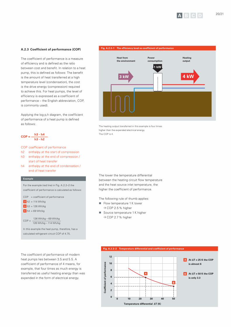
A.2.3 Coefficient of performance (COP)
The coefficient of performance is a measure
of efficiency and is defined as the ratio
between cost and benefit. In relation to a heat
pump, this is defined as follows: The benefit
is the amount of heat transferred at a high
temperature level (condensation), the cost
is the drive energy (compression) required
to achieve this. For heat pumps, the level of
efficiency is expressed as a coefficient of
performance – the English abbreviation, COP,
is commonly used).
Applying the log p,h diagram, the coefficient
of performance of a heat pump is defined
as follows:
COP = h3 - h4
h3 - h2
COP coefficient of performance
h2 enthalpy at the start of compression
h3 enthalpy at the end of compression /
start of heat transfer
h4 enthalpy at the end of condensation /
end of heat transfer
The coefficient of performance of modern
heat pumps lies between 3.5 and 5.5. A
coefficient of performance of 4 means, for
example, that four times as much energy is
transferred as useful heating energy than was
expended in the form of electrical energy.
20/21
Heating output
Heat from the environment
Power consumption
4 kW3 kW
1 kW
?
Fig. A.2.3–1 The efficiency level as coefficient of performance
Fig. A.2.3–2 Temperature differential and coefficient of performance
12
10
8
6
4
2
0
Temperature differential ΔT (K)
Co
effi
cien
t o
f p
erfo
rman
ce
50 40 30 20 10 0
A B
B
A At ΔT = 25 K the COP
is almost 6
At ΔT = 50 K the COP
is only 3.3
Example
For the example (red line) in Fig. A.2.2–2 the
coefficient of performance is calculated as follows:
COP = coefficient of performance
h2 = 114 Wh/kg
h3 = 126 Wh/kg
h4 = 69 Wh/kg
COP = 126 Wh/kg – 69 Wh/kg
126 Wh/kg – 114 Wh/kg
In this example the heat pump, therefore, has a
calculated refrigerant circuit COP of 4.75.
The heating output transferred in this example is four times
higher than the expended electrical energy.
The COP is 4.
The lower the temperature differential
between the heating circuit flow temperature
and the heat source inlet temperature, the
higher the coefficient of performance.
The following rule of thumb applies:
Flow temperature 1 K lower
COP 2.5 % higher
Source temperature 1 K higher
COP 2.7 % higher
A.2 Physical principles
In order to provide comparable coefficient of
performances for heat pumps, calculations
are made in accordance with DIN EN 14511
and measurements taken at fixed operating
points. The operating point is the product
of the inlet temperature of the heat source
medium (air A, brine B, water W) in the
heat pump and the heating water outlet
temperature (secondary circuit flow
temperature).
For the following heat pump types, the
operating points below apply:
Type Inlet
temperature,
heat source
Secondary
circuit flow
temperature
Air/water A 2 °C W 35 °C
Brine/water B 0 °C W 35 °C
Water/water W 10 °C W 35 °C
A stands for air
B stands for brine
W stands for water
The standard takes the drive output of the
heat pump, plus the power consumption
of the heat pump control unit, as well
as a proportion of auxiliary energy into
account, that is required in order to
overcome the internal pressure drop of both
heat exchangers.
This includes the amount of power used by
pumps, control units, etc. The result is given
as the seasonal performance factor :
= QWPWEL
seasonal performance factor
QWP amount of heat in kWh delivered by the
heat pump over the course of a year
WEL electrical power in kWh supplied to the
heat pump over the course of a year
For forecasting purposes, the simplified
calculation process according to
VDI guideline 4650 has become the
established norm. The so-called BIN process
to DIN 18599 is significantly more accurate,
but also more complicated.
At www.viessmann.com
the seasonal performance
factor calculator is
available to use with
heat pumps.
Note
A.2.4 Seasonal performance factor (SPF)
The coefficient of performance (COP) is the
ratio between the heating output and the
power consumption at a single operating
point. The seasonal performance factor is this
ratio over a period of 12 months.
The coefficient of performance is used
to compare heat pumps with regard to
efficiency, yet it is derived from a particular
operating point under defined temperature
conditions.
For engineering purposes (for example, to be
able to specify the consumption costs arising
from using a heat pump), it is necessary
to consider the system's operation over
the whole year. For this, the heat volume
transferred over the year is given in relation
to the overall electrical power drawn by the
heat pump system over the same period.

22/23
A.3 Main components
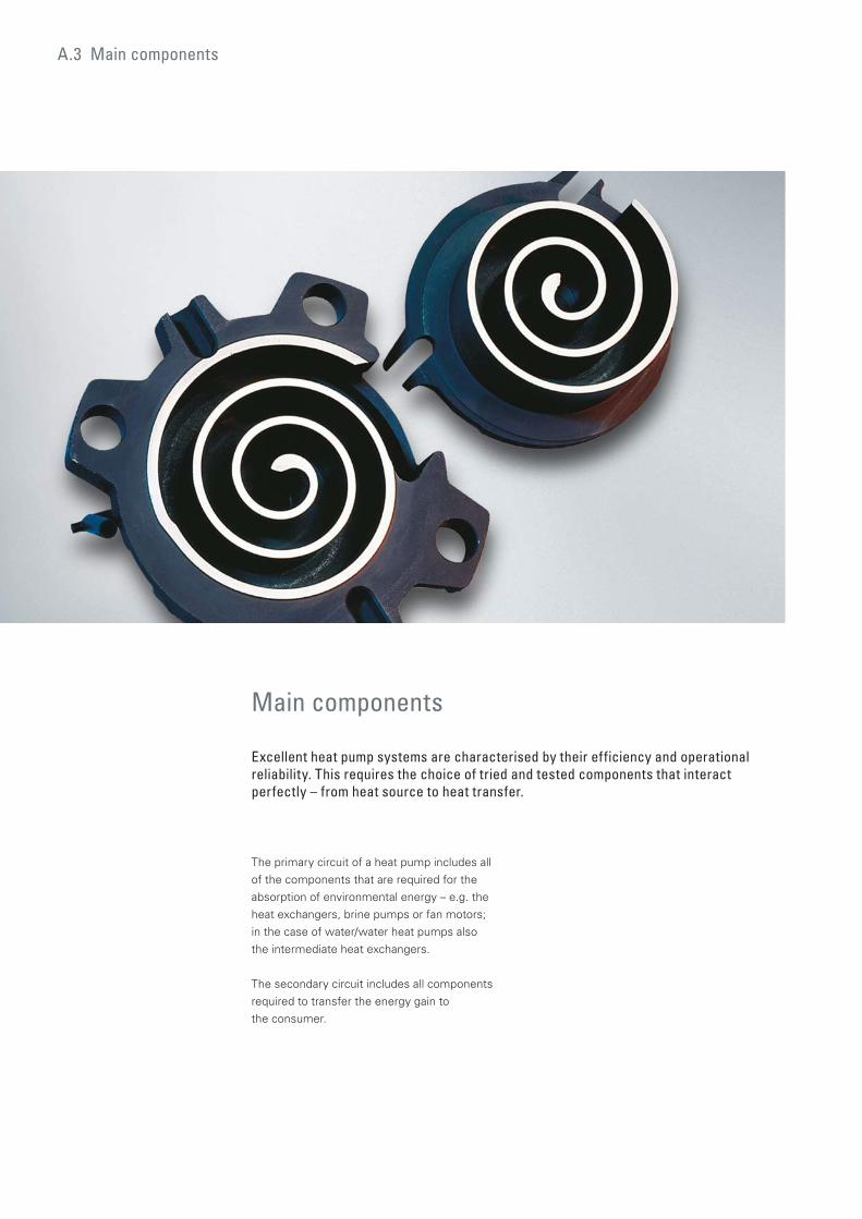
The primary circuit of a heat pump includes all
of the components that are required for the
absorption of environmental energy – e.g. the
heat exchangers, brine pumps or fan motors;
in the case of water/water heat pumps also
the intermediate heat exchangers.
The secondary circuit includes all components
required to transfer the energy gain to
the consumer.
Main components
Excellent heat pump systems are characterised by their efficiency and operational reliability. This requires the choice of tried and tested components that interact perfectly – from heat source to heat transfer.
24/25
Static spiral block
Moving spiral block
A.3.1 Compressor
The compressor is the part of the heat
pump that acts as the "pump" – it sucks in
and compresses the gaseous refrigerant. All
compressors are designed to compress gases
and would be damaged if liquid droplets in the
vapour were to be drawn in. The vapour must
therefore be slightly superheated prior to
entering the compressor. This superheating is
regulated by the expansion valve, the accurate
control of this component being vital to overall
heat pump efficiency.
A.3.1.1 Compressor types
The effectiveness of the compression process
is crucial to the efficiency of a heat pump.
Scroll compressors really come into their
own when used in heat pumps. This type of
compressor is comprised of two interlocking
spirals which compress the refrigerant. Scroll
compressors operate quietly and with low
vibrations; they are maintenance free and
extremely durable.
Rotating piston compressors, reciprocating
piston and screw compressors are also used.
Rotating piston compressors tend to cover the
lower output ranges, scroll compressors the
low to medium and screw compressors the
higher output range.
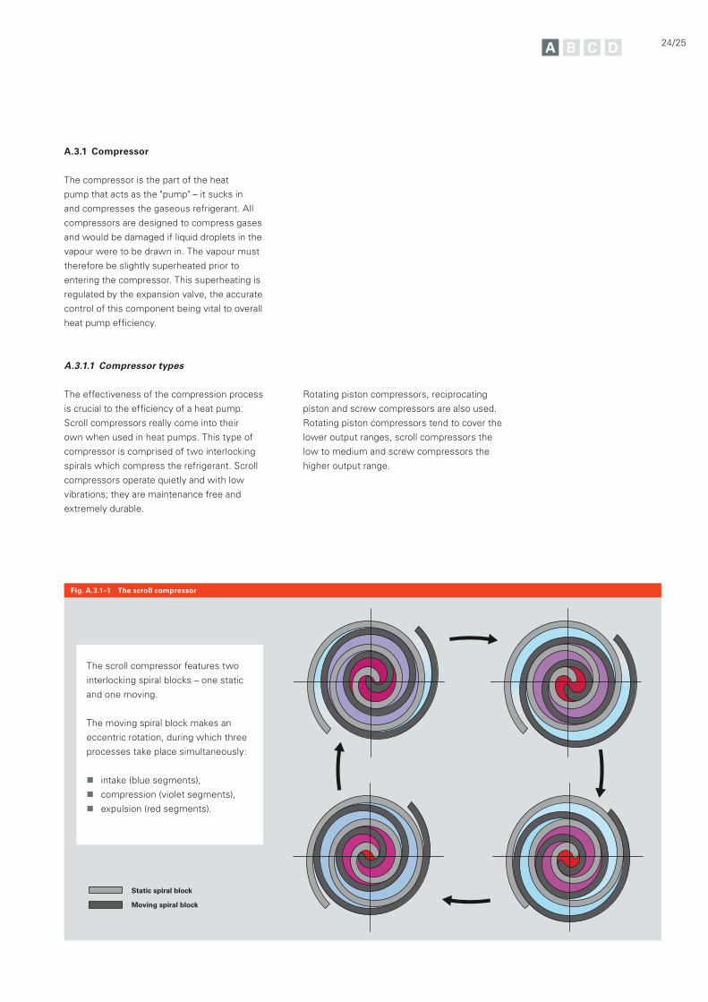
Fig. A.3.1–1 The scroll compressor
The scroll compressor features two
interlocking spiral blocks – one static
and one moving.
The moving spiral block makes an
eccentric rotation, during which three
processes take place simultaneously:
intake (blue segments),
compression (violet segments),
expulsion (red segments).
A.3.1.2 Output control
The importance of output control in
compressors is gaining in significance.
For heat pumps operating with outdoor
air as a primary source, output control is
particularly suitable, as with this type of heat
source major fluctuations in the seasonal
performance factor can occur.
Design output
Design temperature
Heating limit temperature
Outside temperature (°C)
Ou
tpu
t (k
W)
3
3
2
2
1
1
Unregulated air/water heat pump Heat demand
Regulated air/water heat pump
10 20 30 40 50 60 70 80 90 100
0
2
3
4
1
5
0
8
4
12
16
20
Coefficient of performance Heating output (kW)
Co
effi
cien
t o
f p
erfo
rman
ce
Rotating field frequency (Hz)
Hea
tin
g o
utp
ut
(kW
)
3.13
1.27
4.055.15
6.697.21
8.569.66
6.42
2.61
3.70 3.673.76
3.593.46
3.14
3.603.77
In addition, there is a counter-acting trend
between output demand and output provision
– the colder the outdoor air heat source,
the higher the demand for heating energy,
and the greater the temperature differential
between source and available temperature
with corresponding implications for the COP.
If the outside temperature increases, the
heat demand falls whilst the appliance output
rises. In order to prevent frequent cycling
of the heat pump, its output is matched to
these framework conditions. The compressor
output – and consequently also the refrigerant
pressure and temperature – are regulated
accordingly.
Output control can be achieved by several
means. The most frequently applied
method for regulating the compressor
output involves the deployment of inverter
technology – this generates a DC current from
the supply voltage (e.g. 230 V ~). Subject
to the frequency of the rotating field, the
compressor will operate at different speeds
and consequently deliver different output
ratings. Particularly in partial load operation,
inverter compressors operate with a high
degree of efficiency.
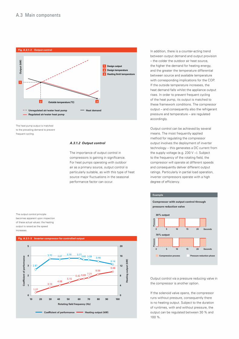
Fig. A.3.1–2 Output control
Fig. A.3.1–3 Inverter compressor for controlled output
The output control principle
becomes apparent upon inspection
of these actual values: the heating
output is raised as the speed
increases.
The heat pump output is matched
to the prevailing demand to prevent
frequent cycling.
A.3 Main components
Example
Compressor with output control through
pressure reduction valve
Seconds
Seconds
50 10 15 20
50 10 15 20
Pre
ssu
reP
ress
ure
Compression process Pressure reduction phase
30% output
70% output
Output control via a pressure reducing valve in
the compressor is another option.
If the solenoid valve opens, the compressor
runs without pressure, consequently there
is no heating output. Subject to the duration
of runtimes, with and without pressure, the
output can be regulated between 30 % and
100 %.
2
1
1
6
3
Evaporator
Scroll compressor
Condenser
5
6
45
Heat exchanger
Expansion valve
Expansion valve
4
3
Liquid
Gaseous
Heating energyEnvironmental heat
Enhanced VapourInjection (EVI)
2
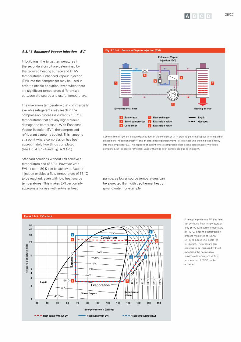
Fig. A.3.1–4 Enhanced Vapour Injection (EVI)
26/27
A.3.1.3 Enhanced Vapour Injection – EVI
In buildings, the target temperatures in
the secondary circuit are determined by
the required heating surface and DHW
temperatures. Enhanced Vapour Injection
(EVI) into the compressor may be used in
order to enable operation, even when there
are significant temperature differentials
between the source and useful temperature.
The maximum temperature that commercially
available refrigerants may reach in the
compression process is currently 135 °C;
temperatures that are any higher would
damage the compressor. With Enhanced
Vapour Injection (EVI), the compressed
refrigerant vapour is cooled. This happens
at a point where compression has been
approximately two thirds completed
(see Fig. A.3.1–4 and Fig. A.3.1–5).
Standard solutions without EVI achieve a
temperature rise of 60 K, however with
EVI a rise of 80 K can be achieved. Vapour
injection enables a flow temperature of 65 °C
to be reached, even with low heat source
temperatures. This makes EVI particularly
appropriate for use with air/water heat
Some of the refrigerant is used downstream of the condenser (3) in order to generate vapour with the aid of
an additional heat exchanger (4) and an additional expansion valve (5). This vapour is then injected directly
into the compressor (2). This happens at a point where compression has been approximately two thirds
completed. EVI cools the refrigerant vapour that has been compressed up to this point.
A heat pump without EVI (red line)
can achieve a flow temperature of
only 55 °C at a source temperature
of –10 °C, since the compression
process must stop at 135 °C.
EVI (3 to 4, blue line) cools the
refrigerant. The pressure can
continue to be increased without
exceeding the permissible
maximum temperature. A flow
temperature of 65 °C can be
achieved.
40
50
30
20
10
5
4
3
2
1
Pre
ssu
re p
ab
solu
te (
bar
)
Energy content h (Wh/kg)
100 110 120 130 140 15080 907050 604030
0°C
10°C
-10°C
20°C
-20°C
30°C
-30°C
-40°C
70°C
60°C
80
°C
60
°C
40
°C
100
°C
120
°C
140
°C
Superheated steam
Steam/vapour
Liquid 1 2
34
3
56
4
Heat pump without EVI Heat pump with EVI Heat pump without EVI
Evaporation
Condenser
Exp
ansi
on
Com
pres
sion
Fig. A.3.1–5 EVI effect
pumps, as lower source temperatures can
be expected than with geothermal heat or
groundwater, for example.
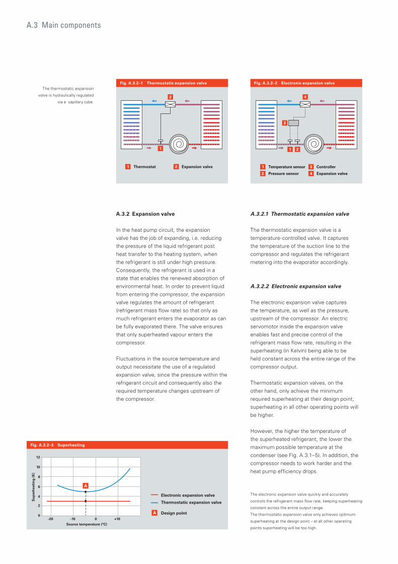
A.3.2 Expansion valve
In the heat pump circuit, the expansion
valve has the job of expanding, i.e. reducing
the pressure of the liquid refrigerant post
heat transfer to the heating system, when
the refrigerant is still under high pressure.
Consequently, the refrigerant is used in a
state that enables the renewed absorption of
environmental heat. In order to prevent liquid
from entering the compressor, the expansion
valve regulates the amount of refrigerant
(refrigerant mass flow rate) so that only as
much refrigerant enters the evaporator as can
be fully evaporated there. The valve ensures
that only superheated vapour enters the
compressor.
Fluctuations in the source temperature and
output necessitate the use of a regulated
expansion valve, since the pressure within the
refrigerant circuit and consequently also the
required temperature changes upstream of
the compressor.
2
2
1 Thermostat Expansion valve
1
4
4
3
2
2
1 Temperature sensor Controller
Pressure sensor Expansion valve
1
3
Fig. A.3.2–1 Thermostatic expansion valve Fig. A.3.2–2 Electronic expansion valve
Fig. A.3.2–3 Superheating
A.3.2.1 Thermostatic expansion valve
The thermostatic expansion valve is a
temperature-controlled valve. It captures
the temperature of the suction line to the
compressor and regulates the refrigerant
metering into the evaporator accordingly.
A.3.2.2 Electronic expansion valve
The electronic expansion valve captures
the temperature, as well as the pressure,
upstream of the compressor. An electric
servomotor inside the expansion valve
enables fast and precise control of the
refrigerant mass flow rate, resulting in the
superheating (in Kelvin) being able to be
held constant across the entire range of the
compressor output.
Thermostatic expansion valves, on the
other hand, only achieve the minimum
required superheating at their design point;
superheating in all other operating points will
be higher.
However, the higher the temperature of
the superheated refrigerant, the lower the
maximum possible temperature at the
condenser (see Fig. A.3.1–5). In addition, the
compressor needs to work harder and the
heat pump efficiency drops.
A.3 Main components
-20 -10 0
Source temperature (°C)
Su
per
hea
tin
g (
K)
+10
10
12
8
6
4
2
0
A
A
Electronic expansion valve
Thermostatic expansion valve
Design point
The electronic expansion valve quickly and accurately
controls the refrigerant mass flow rate, keeping superheating
constant across the entire output range.
The thermostatic expansion valve only achieves optimum
superheating at the design point – at all other operating
points superheating will be too high.
The thermostatic expansion
valve is hydraulically regulated
via a capillary tube.
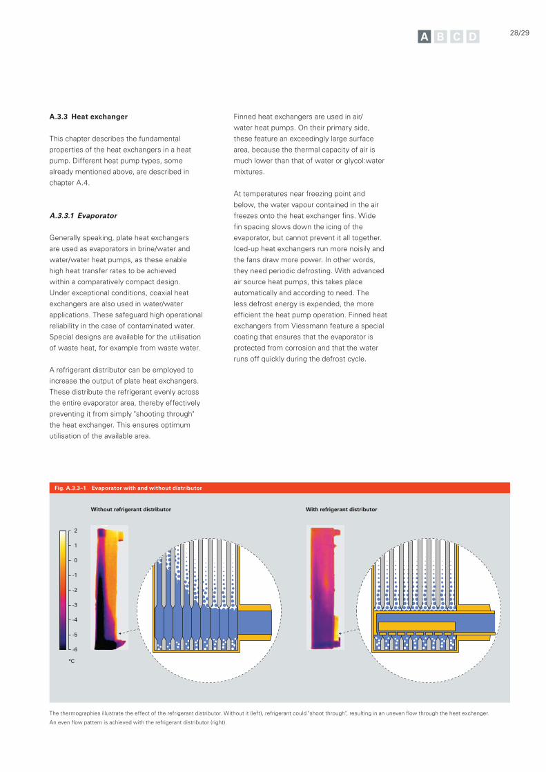
Fig. A.3.3–1 Evaporator with and without distributor
Without refrigerant distributor With refrigerant distributor
2
1
°C
0
-1
-2
-3
-4
-5
-6
28/29
A.3.3 Heat exchanger
This chapter describes the fundamental
properties of the heat exchangers in a heat
pump. Different heat pump types, some
already mentioned above, are described in
chapter A.4.
A.3.3.1 Evaporator
Generally speaking, plate heat exchangers
are used as evaporators in brine/water and
water/water heat pumps, as these enable
high heat transfer rates to be achieved
within a comparatively compact design.
Under exceptional conditions, coaxial heat
exchangers are also used in water/water
applications. These safeguard high operational
reliability in the case of contaminated water.
Special designs are available for the utilisation
of waste heat, for example from waste water.
A refrigerant distributor can be employed to
increase the output of plate heat exchangers.
These distribute the refrigerant evenly across
the entire evaporator area, thereby effectively
preventing it from simply "shooting through"
the heat exchanger. This ensures optimum
utilisation of the available area.
Finned heat exchangers are used in air/
water heat pumps. On their primary side,
these feature an exceedingly large surface
area, because the thermal capacity of air is
much lower than that of water or glycol:water
mixtures.
At temperatures near freezing point and
below, the water vapour contained in the air
freezes onto the heat exchanger fins. Wide
fin spacing slows down the icing of the
evaporator, but cannot prevent it all together.
Iced-up heat exchangers run more noisily and
the fans draw more power. In other words,
they need periodic defrosting. With advanced
air source heat pumps, this takes place
automatically and according to need. The
less defrost energy is expended, the more
efficient the heat pump operation. Finned heat
exchangers from Viessmann feature a special
coating that ensures that the evaporator is
protected from corrosion and that the water
runs off quickly during the defrost cycle.
The thermographies illustrate the effect of the refrigerant distributor. Without it (left), refrigerant could "shoot through", resulting in an uneven flow through the heat exchanger.
An even flow pattern is achieved with the refrigerant distributor (right).
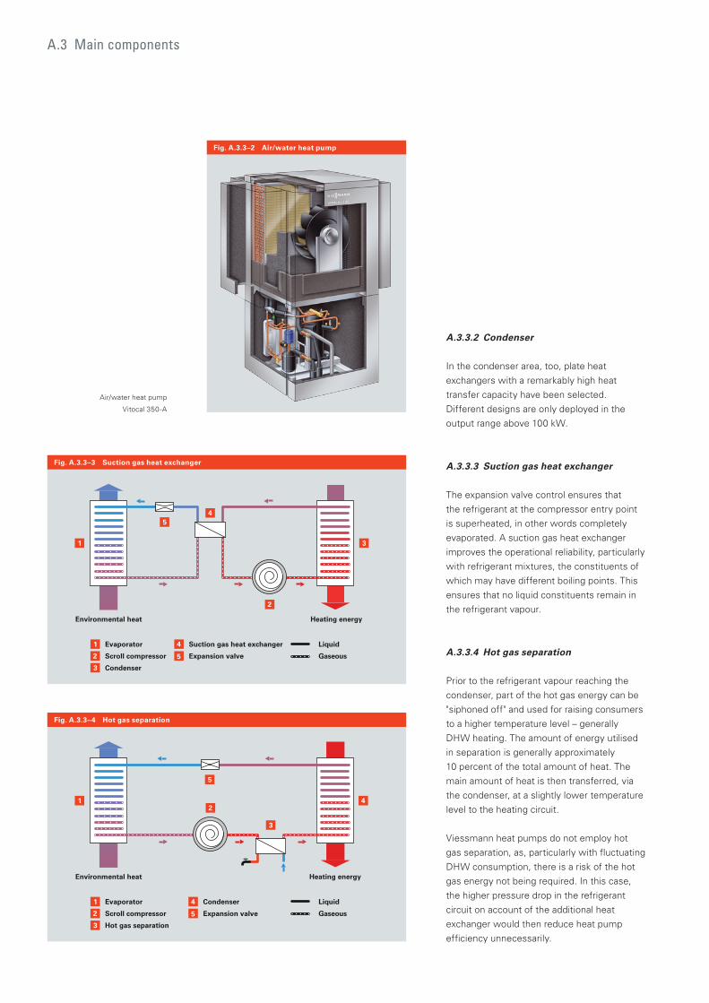
A.3.3.2 Condenser
In the condenser area, too, plate heat
exchangers with a remarkably high heat
transfer capacity have been selected.
Different designs are only deployed in the
output range above 100 kW.
A.3.3.3 Suction gas heat exchanger
The expansion valve control ensures that
the refrigerant at the compressor entry point
is superheated, in other words completely
evaporated. A suction gas heat exchanger
improves the operational reliability, particularly
with refrigerant mixtures, the constituents of
which may have different boiling points. This
ensures that no liquid constituents remain in
the refrigerant vapour.
A.3.3.4 Hot gas separation
Prior to the refrigerant vapour reaching the
condenser, part of the hot gas energy can be
"siphoned off" and used for raising consumers
to a higher temperature level – generally
DHW heating. The amount of energy utilised
in separation is generally approximately
10 percent of the total amount of heat. The
main amount of heat is then transferred, via
the condenser, at a slightly lower temperature
level to the heating circuit.
Viessmann heat pumps do not employ hot
gas separation, as, particularly with fluctuating
DHW consumption, there is a risk of the hot
gas energy not being required. In this case,
the higher pressure drop in the refrigerant
circuit on account of the additional heat
exchanger would then reduce heat pump
efficiency unnecessarily.
2
1
1
4
3
Evaporator
Scroll compressor
Condenser
5
5
Suction gas heat exchanger
Expansion valve
4
3
Liquid
Gaseous
Heating energyEnvironmental heat
2
2
1
1 4
3
Evaporator
Scroll compressor
Hot gas separation
5
5
Condenser
Expansion valve
4
3
Liquid
Gaseous
Heating energyEnvironmental heat
2
Fig. A.3.3–3 Suction gas heat exchanger
Fig. A.3.3–4 Hot gas separation
A.3 Main components
Fig. A.3.3–2 Air/water heat pump
Air/water heat pump
Vitocal 350-A
30/31
A.3.4 Refrigerant
The refrigerant draws heating energy from
the heat source (air, ground or water) during
evaporation and transports it to the consumer,
where it condenses again. Energy is always
available in these phase changes. Purely
theoretically, though, any substance can be
thought of as a refrigerant.
However, a refrigerant suitable for heat pumps
must possess some special properties, i.e. it
should have as low a boiling point as possible,
a low evaporation volume and a high cooling
capacity, relative to its volume. In addition,
it must not be corrosive to the components
and lubricants employed, if possible it should
be non-poisonous, non-explosive and non-
flammable. Effects on the ozone layer (ODP =
Ozone Depletion Potential) and its greenhouse
effect (GWP = Global Warming Potential)
should be as low as possible.
Partially halogenated chlorofluorocarbons
(H-CFC) best meet these requirements,
and so are generally used in heat pumps.
Apart from synthesised refrigerants, natural
refrigerants, such as CO2, propane or butane
are also used in some applications. Since the
latter two substances are explosive, their
use would place high demands on the safety
equipment.
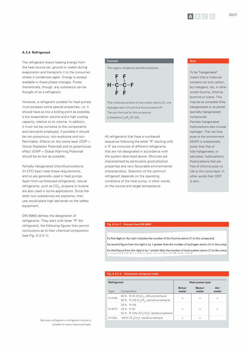
DIN 8960 defines the designation of
refrigerants. They start with letter "R" (for
refrigerant), the following figures then permit
conclusions as to their chemical composition
(see Fig. A.3.4–1).
All refrigerants that have a numbered
sequence following the letter "R" starting with
a "4" are mixtures of different refrigerants
that are not designated in accordance with
the system described above. Mixtures are
characterised by particularly good physical
properties and very favourable environmental
characteristics. Selection of the optimum
refrigerant depends on the operating
conditions of the heat pump, in other words,
on the source and target temperature.
To be "halogenated"
means that a molecule
contains not only carbon,
but halogens, too, in other
words fluorine, chlorine,
bromine or iodine. This
may be as complete (fully
halogenated) or as partial
(partially halogenated)
compounds.
Partially halogenated
hydrocarbons also include
hydrogen. The risk they
pose to the environment
(GWP) is substantially
lower than that of
fully halogenated, or
saturated, hydrocarbons.
Hydrocarbons that are
free of chlorine pose no
risk to the ozone layer, in
other words their ODP
is zero.
Note
Refrigerant Heat pump type
Type
Composition
Brine/water
Water/water
Air/ water
R-410A50 % R-32 (CH2F2, difluoromethane)
50 % R-125 (C2HF5, pentafluoroethane)x x x
R-407C
25 % R-125
23 % R-32
52 % R-134a (CF3CH2F, tetrafluoroethane)
x x x
R-134a 100 % CF3CH2F, tetrafluoroethane x x
Fig. A.3.4–2 Viessmann refrigerant table
Fig. A.3.4–1 Extract from DIN 8960
Not every refrigerant or refrigerant mixture is
suitable for every heat pump type.
Example
The organic refrigerant pentafluoroethane:
This molecule consists of two carbon atoms (C), one
hydrogen atom (H) and five fluorine atoms (F).
The sum formula for this compound
is therefore C2HF5 (R-125).

A.4 Primary source potentials
Primary source potentials
Heat pumps predominantly use heat from
the ground, outdoor air or water as a primary
energy source. However, heat pumps can also
convert waste heat that would otherwise be
left unused, into useful energy.
The following chapters describe the different
primary sources and the different types of
heat pump that can be used to exploit them.
Heat from the sun is stored in the air, water and the ground. This environmental heat is therefore a renewable form of energy that can be utilised by heat pumps.
32/33
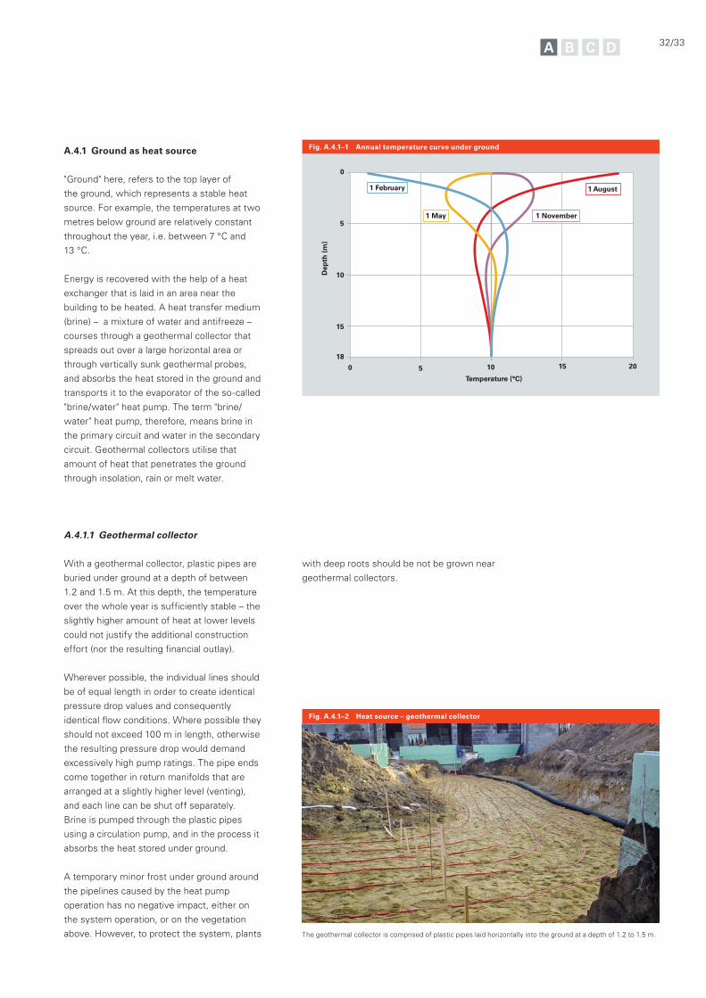
A.4.1 Ground as heat source
"Ground" here, refers to the top layer of
the ground, which represents a stable heat
source. For example, the temperatures at two
metres below ground are relatively constant
throughout the year, i.e. between 7 °C and
13 °C.
Energy is recovered with the help of a heat
exchanger that is laid in an area near the
building to be heated. A heat transfer medium
(brine) – a mixture of water and antifreeze –
courses through a geothermal collector that
spreads out over a large horizontal area or
through vertically sunk geothermal probes,
and absorbs the heat stored in the ground and
transports it to the evaporator of the so-called
"brine/water" heat pump. The term "brine/
water" heat pump, therefore, means brine in
the primary circuit and water in the secondary
circuit. Geothermal collectors utilise that
amount of heat that penetrates the ground
through insolation, rain or melt water.
Fig. A.4.1–1 Annual temperature curve under ground
A.4.1.1 Geothermal collector
With a geothermal collector, plastic pipes are
buried under ground at a depth of between
1.2 and 1.5 m. At this depth, the temperature
over the whole year is sufficiently stable – the
slightly higher amount of heat at lower levels
could not justify the additional construction
effort (nor the resulting financial outlay).
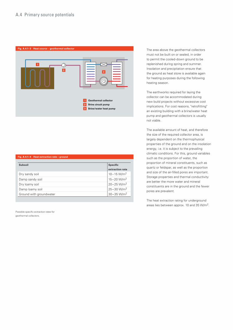
Wherever possible, the individual lines should
be of equal length in order to create identical
pressure drop values and consequently
identical flow conditions. Where possible they
should not exceed 100 m in length, otherwise
the resulting pressure drop would demand
excessively high pump ratings. The pipe ends
come together in return manifolds that are
arranged at a slightly higher level (venting),
and each line can be shut off separately.
Brine is pumped through the plastic pipes
using a circulation pump, and in the process it
absorbs the heat stored under ground.
A temporary minor frost under ground around
the pipelines caused by the heat pump
operation has no negative impact, either on
the system operation, or on the vegetation
above. However, to protect the system, plants
Fig. A.4.1–2 Heat source – geothermal collector
0
5
10
15
18
Temperature (°C)
Dep
th (
m)
15 201050
1 February 1 August
1 November1 May
with deep roots should be not be grown near
geothermal collectors.
The geothermal collector is comprised of plastic pipes laid horizontally into the ground at a depth of 1.2 to 1.5 m.
The area above the geothermal collectors
must not be built on or sealed, in order
to permit the cooled-down ground to be
replenished during spring and summer.
Insolation and precipitation ensure that
the ground as heat store is available again
for heating purposes during the following
heating season.
The earthworks required for laying the
collector can be accommodated during
new build projects without excessive cost
implications. For cost reasons, "retrofitting"
an existing building with a brine/water heat
pump and geothermal collectors is usually
not viable.
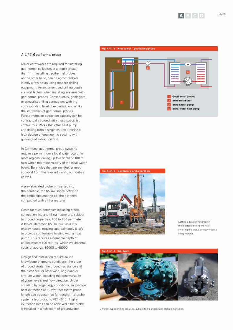
The available amount of heat, and therefore
the size of the required collector area, is
largely dependent on the thermophysical
properties of the ground and on the insolation
energy, i.e. it is subject to the prevailing
climatic conditions. For this, ground variables
such as the proportion of water, the
proportion of mineral constituents, such as
quartz or feldspar, as well as the proportion
and size of the air-filled pores are important.
Storage properties and thermal conductivity
are better the more water and mineral
constituents are in the ground and the fewer
pores are prevalent.
The heat extraction rating for underground
areas lies between approx. 10 and 35 W/m2.
Fig. A.4.1–3 Heat source – geothermal collector
A.4 Primary source potentials
3
2
1 Geothermal collector
Brine circuit pump
Brine/water heat pump3
2
1
Fig. A.4.1–4 Heat extraction rate – ground
Possible specific extraction rates for
geothermal collectors.
Subsoil Specific
extraction rate
Dry sandy soil 10 – 15 W/m2
Damp sandy soil 15 – 20 W/m2
Dry loamy soil 20 – 25 W/m2
Damp loamy soil 25 – 30 W/m2
Ground with groundwater 30 – 35 W/m2
34/35
Fig. A.4.1–6 Geothermal probe borehole
Fig. A.4.1–7 Drill types
A.4.1.2 Geothermal probe
Major earthworks are required for installing
geothermal collectors at a depth greater
than 1 m. Installing geothermal probes,
on the other hand, can be accomplished
in only a few hours using modern drilling
equipment. Arrangement and drilling depth
are vital factors when installing systems with
geothermal probes. Consequently, geologists,
or specialist drilling contractors with the
corresponding level of expertise, undertake
the installation of geothermal probes.
Furthermore, an extraction capacity can be
contractually agreed with these specialist
contractors. Packs that offer heat pump
and drilling from a single source promise a
high degree of engineering security with
guaranteed extraction rate.
In Germany, geothermal probe systems
require a permit from a local water board. In
most regions, drilling up to a depth of 100 m
falls within the responsibility of the local water
board. Boreholes that are any deeper need
approval from the relevant mining authorities
as well.
A pre-fabricated probe is inserted into
the borehole, the hollow space between
the probe pipe and the borehole is then
compacted with a filler material.
Costs for such boreholes including probe,
connection line and filling matter are, subject
to ground properties, €60 to €80 per meter.
A typical detached house, built as a low
energy house, requires approximately 6 kW
to provide comfortable heating with a heat
pump. This requires a borehole depth of
approximately 100 metres, which would entail
costs of approx. €6000 to €8000.
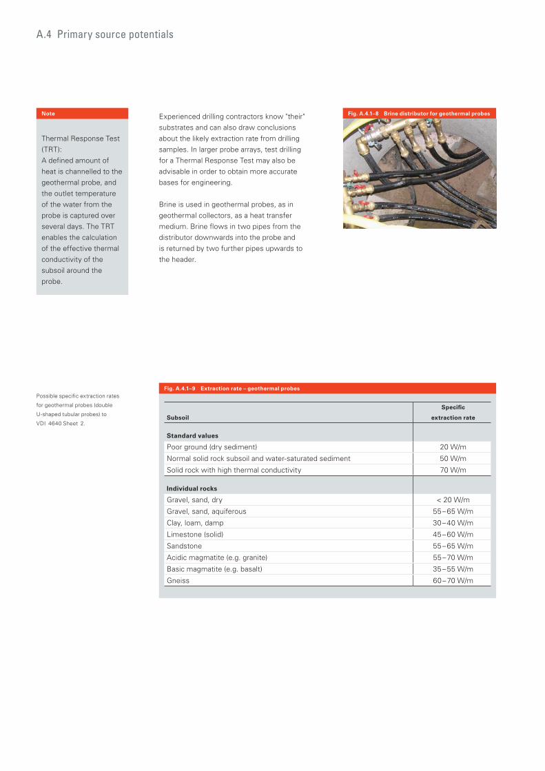
Design and installation require sound
knowledge of ground conditions, the order
of ground strata, the ground resistance and
the presence, or otherwise, of ground or
stratum water, including the determination
of water levels and flow direction. Under
standard hydrogeology conditions, an average
heat extraction of 50 watt per metre probe
length can be assumed for geothermal probe
systems (according to VDI 4640). Higher
extraction rates can be achieved if the probe
is installed in a rich seam of groundwater.
Fig. A.4.1–5 Heat source – geothermal probe
4
3
1 Geothermal probes
Brine distributor
Brine circuit pump
Brine/water heat pump
2
2
3
4
1
Setting a geothermal probe in
three stages: drilling the hole;
inserting the probe; compacting the
filling material.
Different types of drills are used, subject to the subsoil and probe dimensions.
Experienced drilling contractors know "their"
substrates and can also draw conclusions
about the likely extraction rate from drilling
samples. In larger probe arrays, test drilling
for a Thermal Response Test may also be
advisable in order to obtain more accurate
bases for engineering.
Brine is used in geothermal probes, as in
geothermal collectors, as a heat transfer
medium. Brine flows in two pipes from the
distributor downwards into the probe and
is returned by two further pipes upwards to
the header.
Fig. A.4.1–9 Extraction rate – geothermal probes
Fig. A.4.1–8 Brine distributor for geothermal probes
Possible specific extraction rates
for geothermal probes (double
U-shaped tubular probes) to
VDI 4640 Sheet 2.Subsoil
Specific
extraction rate
Standard values
Poor ground (dry sediment) 20 W/m
Normal solid rock subsoil and water-saturated sediment 50 W/m
Solid rock with high thermal conductivity 70 W/m
Individual rocks
Gravel, sand, dry < 20 W/m
Gravel, sand, aquiferous 55 – 65 W/m
Clay, loam, damp 30 – 40 W/m
Limestone (solid) 45 – 60 W/m
Sandstone 55 – 65 W/m
Acidic magmatite (e.g. granite) 55 – 70 W/m
Basic magmatite (e.g. basalt) 35 – 55 W/m
Gneiss 60 – 70 W/m
A.4 Primary source potentials
Thermal Response Test
(TRT):
A defined amount of
heat is channelled to the
geothermal probe, and
the outlet temperature
of the water from the
probe is captured over
several days. The TRT
enables the calculation
of the effective thermal
conductivity of the
subsoil around the
probe.
Note
36/37
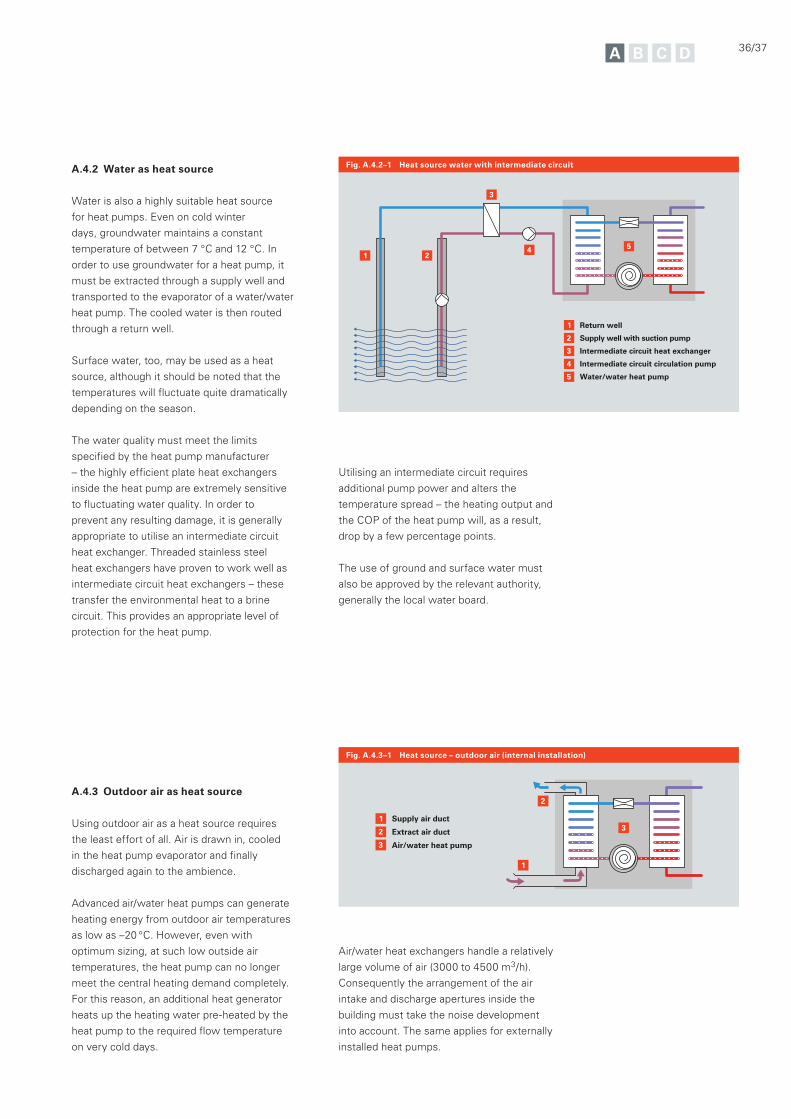
A.4.2 Water as heat source
Water is also a highly suitable heat source
for heat pumps. Even on cold winter
days, groundwater maintains a constant
temperature of between 7 °C and 12 °C. In
order to use groundwater for a heat pump, it
must be extracted through a supply well and
transported to the evaporator of a water/water
heat pump. The cooled water is then routed
through a return well.
Surface water, too, may be used as a heat
source, although it should be noted that the
temperatures will fluctuate quite dramatically
depending on the season.
The water quality must meet the limits
specified by the heat pump manufacturer
– the highly efficient plate heat exchangers
inside the heat pump are extremely sensitive
to fluctuating water quality. In order to
prevent any resulting damage, it is generally
appropriate to utilise an intermediate circuit
heat exchanger. Threaded stainless steel
heat exchangers have proven to work well as
intermediate circuit heat exchangers – these
transfer the environmental heat to a brine
circuit. This provides an appropriate level of
protection for the heat pump.
A.4.3 Outdoor air as heat source
Using outdoor air as a heat source requires
the least effort of all. Air is drawn in, cooled
in the heat pump evaporator and finally
discharged again to the ambience.
Advanced air/water heat pumps can generate
heating energy from outdoor air temperatures
as low as –20 °C. However, even with
optimum sizing, at such low outside air
temperatures, the heat pump can no longer
meet the central heating demand completely.
For this reason, an additional heat generator
heats up the heating water pre-heated by the
heat pump to the required flow temperature
on very cold days.
Utilising an intermediate circuit requires
additional pump power and alters the
temperature spread – the heating output and
the COP of the heat pump will, as a result,
drop by a few percentage points.
The use of ground and surface water must
also be approved by the relevant authority,
generally the local water board.
Fig. A.4.2–1 Heat source water with intermediate circuit
Fig. A.4.3–1 Heat source – outdoor air (internal installation)
5
2
2
1
1
Return well
Supply well with suction pump
Intermediate circuit heat exchanger
Intermediate circuit circulation pump
Water/water heat pump
3
3
4
4
5
32
2
1
1
Supply air duct
Extract air duct
Air/water heat pump3
Air/water heat exchangers handle a relatively
large volume of air (3000 to 4500 m3/h).
Consequently the arrangement of the air
intake and discharge apertures inside the
building must take the noise development
into account. The same applies for externally
installed heat pumps.
5
2
2
1
1
Drain
Waste water
Waste water heat exchanger
Circulation pump
Water/water heat pump3
3
4
4
5
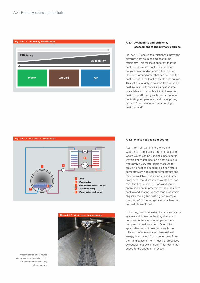
Fig. A.4.5–1 Heat source – waste water
Fig. A.4.5–2 Waste water heat exchanger
Fig. A.4.4–1 Availability and efficiency A.4.4 Availability and efficiency –
assessment of the primary sources
Fig. A.4.4–1 shows the relationship between
different heat sources and heat pump
efficiency. This makes it apparent that the
heat pump is at its most efficient when
coupled to groundwater as a heat source.
However, groundwater that can be used for
heat pumps is the least available heat source.
This ratio is roughly in balance for ground as
heat source. Outdoor air as a heat source
is available almost without limit. However,
heat pump efficiency suffers on account of
fluctuating temperatures and the opposing
cycle of "low outside temperature, high
heat demand".
Water Ground Air
Efficiency
Availability
Waste water as a heat source
can provide a comparatively high
source temperature at a very
affordable rate.
A.4.5 Waste heat as heat source
Apart from air, water and the ground,
waste heat, too, such as from extract air or
waste water, can be used as a heat source.
Developing waste heat as a heat source is
frequently a very affordable measure for
providing heat and cooling, as it can offer a
comparatively high source temperature and
may be available continuously. In industrial
processes, the utilisation of waste heat can
raise the heat pump COP or significantly
optimise an entire process that requires both
cooling and heating. Where food production
requires cooling and heating, for example,
"both sides" of the refrigeration machine can
be usefully employed.
Extracting heat from extract air in a ventilation
system and its use for heating domestic
hot water or heating the supply air has a
comparable positive effect. One highly
appropriate form of heat recovery is the
utilisation of waste water. Here residual
energy is extracted from waste water from
the living space or from industrial processes
by special heat exchangers. This heat is then
added to the upstream process.
A.4 Primary source potentials

38/39
Fig. A.4.6–1 Heat source – non-glazed absorberA.4.6 Absorber with solar backup
Solar collectors or non-glazed absorbers,
too, can be used to improve the temperature
level on the primary side of the heat pump.
This way, the insolation is used directly for
improving the efficiency level.
For example, non-glazed absorbers that utilise
the ambient temperature as a heat source
can be linked into the evaporator circuit.
The absorber is regenerated by insolation
in constant operation, in other words, the
temperature is held at a high level. With this
combination, the improvements of the COP
depend on the weather, i.e. they are not
constant, as particularly during the heating
season insolation is not reliably available.
In sizing the absorber, it must be taken into
account that it might be covered by snow for
certain periods, meaning that insolation can
then not be used at all.
In the case of solar thermal systems for solar
central heating backup, any energy in combi
or buffer cylinders no longer useful to the
heating circuit can be used, theoretically at
least, for the heat pump by cooling down the
cylinder by a few Kelvin. The efficiency of
the heat pump (higher source temperature)
and the collector system (lower return
temperature) would be improved by such a
combination.
However, in practical terms, the achievable
utilisation would never justify the necessary
technical effort. Utilising the phase change in
heat stores [heat sources] offers a sensible
combination of solar thermal system and
heat pump.
Historic photographs of non-
glazed solar absorbers that
utilise insolation and ambient
temperature as heat source.
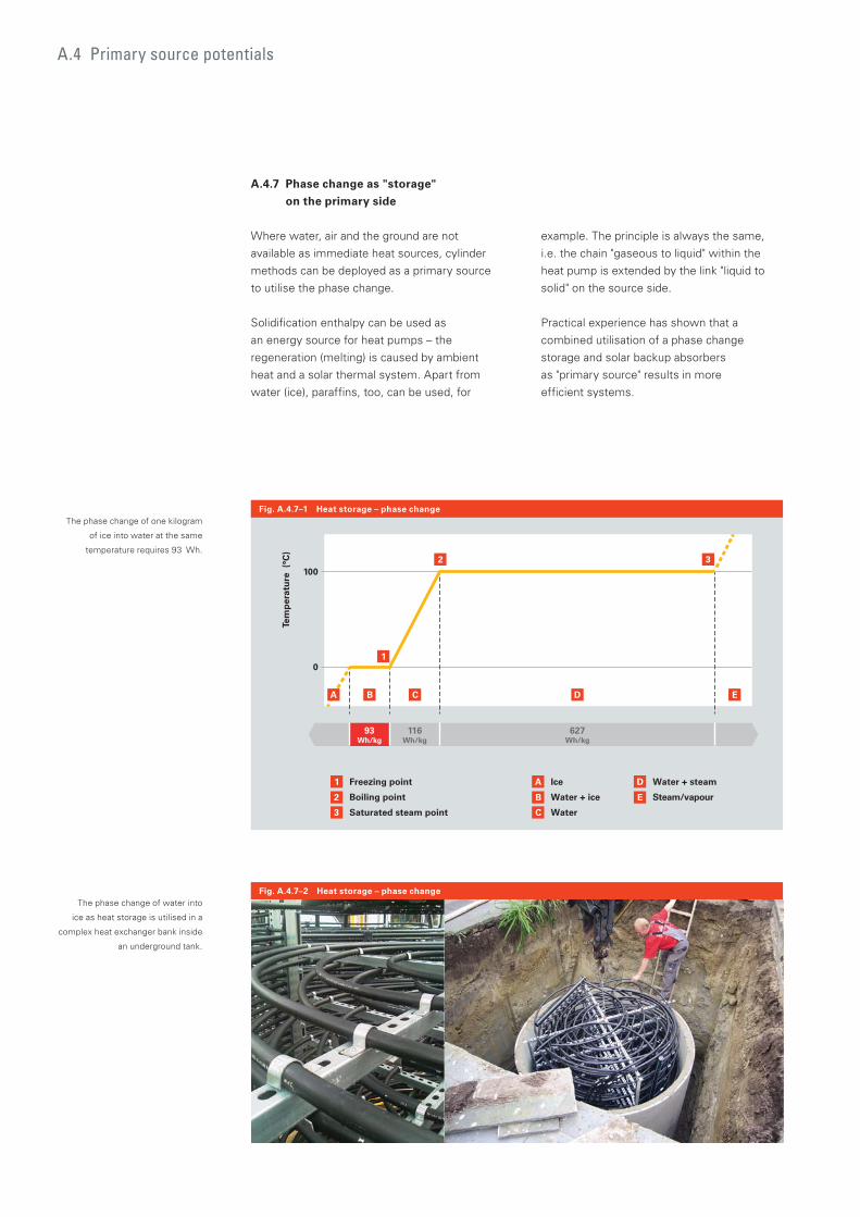
A.4.7 Phase change as "storage"
on the primary side
Where water, air and the ground are not
available as immediate heat sources, cylinder
methods can be deployed as a primary source
to utilise the phase change.
Solidification enthalpy can be used as
an energy source for heat pumps – the
regeneration (melting) is caused by ambient
heat and a solar thermal system. Apart from
water (ice), paraffins, too, can be used, for
The phase change of one kilogram
of ice into water at the same
temperature requires 93 Wh.
Tem
per
atu
re (
°C)
116Wh/kg
627Wh/kg
93Wh/kg
0
1003
EDCB
2
1
1 Freezing point
Boiling point
Saturated steam point
2
3
A Ice
Water + ice
Water
B
C
D Water + steam
Steam/vapourE
A
Fig. A.4.7–1 Heat storage – phase change
A.4 Primary source potentials
example. The principle is always the same,
i.e. the chain "gaseous to liquid" within the
heat pump is extended by the link "liquid to
solid" on the source side.
Practical experience has shown that a
combined utilisation of a phase change
storage and solar backup absorbers
as "primary source" results in more
efficient systems.
The phase change of water into
ice as heat storage is utilised in a
complex heat exchanger bank inside
an underground tank.
Fig. A.4.7–2 Heat storage – phase change

40/41
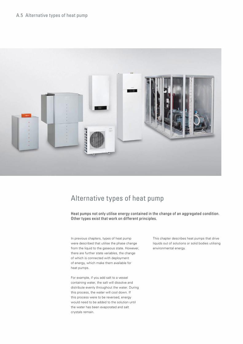
A.5 Alternative types of heat pump
Alternative types of heat pump
Heat pumps not only utilise energy contained in the change of an aggregated condition. Other types exist that work on different principles.
In previous chapters, types of heat pump
were described that utilise the phase change
from the liquid to the gaseous state. However,
there are further state variables, the change
of which is connected with deployment
of energy, which make them available for
heat pumps.
For example, if you add salt to a vessel
containing water, the salt will dissolve and
distribute evenly throughout the water. During
this process, the water will cool down. If
this process were to be reversed, energy
would need to be added to the solution until
the water has been evaporated and salt
crystals remain.
This chapter describes heat pumps that drive
liquids out of solutions or solid bodies utilising
environmental energy.
42/43
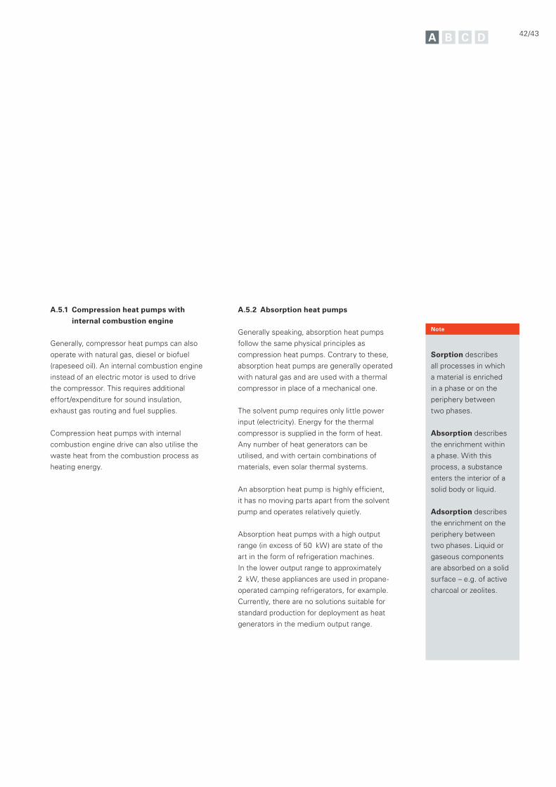
A.5.1 Compression heat pumps with
internal combustion engine
Generally, compressor heat pumps can also
operate with natural gas, diesel or biofuel
(rapeseed oil). An internal combustion engine
instead of an electric motor is used to drive
the compressor. This requires additional
effort/expenditure for sound insulation,
exhaust gas routing and fuel supplies.
Compression heat pumps with internal
combustion engine drive can also utilise the
waste heat from the combustion process as
heating energy.
A.5.2 Absorption heat pumps
Generally speaking, absorption heat pumps
follow the same physical principles as
compression heat pumps. Contrary to these,
absorption heat pumps are generally operated
with natural gas and are used with a thermal
compressor in place of a mechanical one.
The solvent pump requires only little power
input (electricity). Energy for the thermal
compressor is supplied in the form of heat.
Any number of heat generators can be
utilised, and with certain combinations of
materials, even solar thermal systems.
An absorption heat pump is highly efficient,
it has no moving parts apart from the solvent
pump and operates relatively quietly.
Absorption heat pumps with a high output
range (in excess of 50 kW) are state of the
art in the form of refrigeration machines.
In the lower output range to approximately
2 kW, these appliances are used in propane-
operated camping refrigerators, for example.
Currently, there are no solutions suitable for
standard production for deployment as heat
generators in the medium output range.
Sorption describes
all processes in which
a material is enriched
in a phase or on the
periphery between
two phases.
Absorption describes
the enrichment within
a phase. With this
process, a substance
enters the interior of a
solid body or liquid.
Adsorption describes
the enrichment on the
periphery between
two phases. Liquid or
gaseous components
are absorbed on a solid
surface – e.g. of active
charcoal or zeolites.
Note
A.5 Alternative types of heat pump
6
2
2
1
1
Evaporator
Expansion valve
Absorber 6
7
7
5
5
Expansion valve
Solvent pump
Generator
Condenser
4
4
3
3
Liquid
Gaseous
Heating energy
Environmental heat
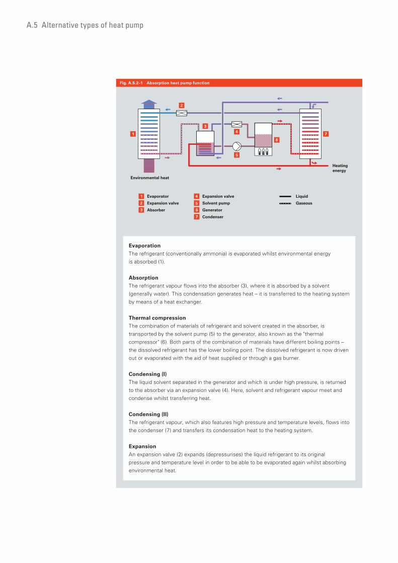
Fig. A.5.2–1 Absorption heat pump function
Evaporation
The refrigerant (conventionally ammonia) is evaporated whilst environmental energy
is absorbed (1).
Absorption
The refrigerant vapour flows into the absorber (3), where it is absorbed by a solvent
(generally water). This condensation generates heat – it is transferred to the heating system
by means of a heat exchanger.
Thermal compression
The combination of materials of refrigerant and solvent created in the absorber, is
transported by the solvent pump (5) to the generator, also known as the "thermal
compressor" (6). Both parts of the combination of materials have different boiling points –
the dissolved refrigerant has the lower boiling point. The dissolved refrigerant is now driven
out or evaporated with the aid of heat supplied or through a gas burner.
Condensing (I)
The liquid solvent separated in the generator and which is under high pressure, is returned
to the absorber via an expansion valve (4). Here, solvent and refrigerant vapour meet and
condense whilst transferring heat.
Condensing (II)
The refrigerant vapour, which also features high pressure and temperature levels, flows into
the condenser (7) and transfers its condensation heat to the heating system.
Expansion
An expansion valve (2) expands (depressurises) the liquid refrigerant to its original
pressure and temperature level in order to be able to be evaporated again whilst absorbing
environmental heat.
44/45
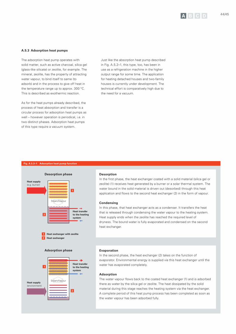
A.5.3 Adsorption heat pumps
The adsorption heat pump operates with
solid matter, such as active charcoal, silica gel
(glass-like silicate) or zeolite, for example. The
mineral, zeolite, has the property of attracting
water vapour, to bind itself to same (to
adsorb) and in the process to give off heat in
the temperature range up to approx. 300 °C.
This is described as exothermic reaction.
As for the heat pumps already described, the
process of heat absorption and transfer is a
circular process for adsorption heat pumps as
well – however operation is periodical, i.e. in
two distinct phases. Adsorption heat pumps
of this type require a vacuum system.
Fig. A.5.3–1 Adsorption heat pump function
Just like the absorption heat pump described
in Fig. A.5.2–1, this type, too, has been in
use as a refrigeration machine in the higher
output range for some time. The application
for heating detached houses and two-family
houses is currently under development. The
technical effort is comparatively high due to
the need for a vacuum.
2
2
1
1
2
1
Heat exchanger with zeolite
Heat exchanger
Heat supply (e.g. burner)
Heat transfer to the heating system
Heat supply (environment)
Heat transfer to the heating system
Steam/Vapour
Steam/Vapour
Desorption phase
Adsorption phase
Desorption
In the first phase, the heat exchanger coated with a solid material (silica gel or
zeolite) (1) receives heat generated by a burner or a solar thermal system. The
water bound in the solid material is driven out (desorbed) through this heat
application and flows to the second heat exchanger (2) in the form of vapour.
Condensing
In this phase, that heat exchanger acts as a condenser. It transfers the heat
that is released through condensing the water vapour to the heating system.
Heat supply ends when the zeolite has reached the required level of
dryness. The bound water is fully evaporated and condensed on the second
heat exchanger.
Evaporation
In the second phase, the heat exchanger (2) takes on the function of
evaporator. Environmental energy is supplied via this heat exchanger until the
water has evaporated completely.
Adsorption
The water vapour flows back to the coated heat exchanger (1) and is adsorbed
there as water by the silica gel or zeolite. The heat dissipated by the solid
material during this stage reaches the heating system via the heat exchanger.
A complete period of this heat pump process has been completed as soon as
the water vapour has been adsorbed fully.


46/47
generators, questions about the availability
and affordability of the electricity required to
power the compressor remain deep areas
of concern.
This chapter deals with the factors that are
crucial for assessing the feasibility of using
heat pumps.
Today, many factors influence the decision
as to whether to invest in the potential this
new type of heating system has to offer.
How futureproof is the decision for a certain
type of fuel? Does the system meet all
statutory requirements? Is the investment
worthwhile when it comes to the expected
operating costs?
These questions must also be able to be
answered in connection with the use of a
heat pump. Contrary to conventional heat
48 B.1 "Electrical power" as the driving energy
49 B.1.1 Power mix in Germany
51 B.1.2 Security of supply
53 B.1.3 Smart metering
54 B.1.4 Heat pumps and photovoltaics
55 B.1.5 Competition for electric power
56 B.2 Statutory framework conditions
57 B.2.1 Heat pumps in the EnEV
59 B.2.2 Heat pumps in the Renewable Energies Heat Act
[EEWärmeG]
59 B.2.3 European framework directives
60 B.3 Economic considerations
B General conditions
Before investing in a heat pump system, customers are sure to want to go through a proper consultation phase. To advise them successfully, a simple understanding of how the appliance works is no longer enough – greater expertise is required.

B.1 "Electrical power" as the driving energy
The utilisation of fossil fuels, which have
provided us with heat over the past 100 years,
is now in transition.
Effects on our climate, reducing availability
and the rising costs of gas, oil and coal have
contributed to the fact that solar energy and
biomass, and now heat pumps, have become
a permanent fixture in the portfolio and not
only in the German heating technology sector.
The number of heat pumps as a proportion
of the heat generators installed each year in
Germany has been on the rise since 1990.
"Electrical power" as the driving energy
For heat pumps with an electrical drive, power consumption is a key factor. The following chapter describes the way this subject should be correctly addressed.
48/49
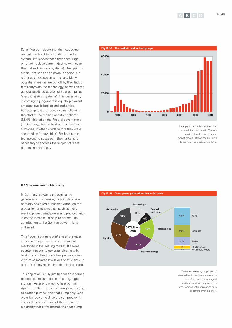
Fig. B.1–1 The market trend for heat pumps
Fig. B1.11 Gross power generation 2009 in Germany
Sales figures indicate that the heat pump
market is subject to fluctuations due to
external influences that either encourage
or retard its development (just as with solar
thermal and biomass systems). Heat pumps
are still not seen as an obvious choice, but
rather as an exception to the rule. Many
potential investors are put off by their lack of
familiarity with the technology, as well as the
general public perception of heat pumps as
"electric heating systems". This uncertainty
in coming to judgement is equally prevalent
amongst public bodies and authorities.
For example, it took seven years following
the start of the market incentive scheme
(MAP) initiated by the Federal government
[of Germany], before heat pumps received
subsidies, in other words before they were
accepted as "renewables". For heat pump
technology to succeed in the market it is
necessary to address the subject of "heat
pumps and electricity".
B.1.1 Power mix in Germany
In Germany, power is predominantly
generated in condensing power stations –
primarily coal fired or nuclear. Although the
proportion of renewables, such as hydro-
electric power, wind power and photovoltaics
is on the increase, at only 18 percent, its
contribution to the German power mix is
still small.
This figure is at the root of one of the most
important prejudices against the use of
electricity in the heating market. It seems
counter-intuitive to generate electricity by
heat in a coal fired or nuclear power station
with its associated low levels of efficiency, in
order to reconvert this into heat in a building.
This objection is fully justified when it comes
to electrical resistance heaters (e.g. night
storage heaters), but not to heat pumps.
Apart from the electrical auxiliary energy (e.g.
circulation pumps), the heat pump only uses
electrical power to drive the compressor. It
is only the consumption of this amount of
electricity that differentiates the heat pump
20102005200019951990198519800
20 000
40 000
60 000
Lignite
Nuclear energy
Renewables
Wind
Biomass
Water
PhotovoltaicHousehold waste
Anthracite
Natural gas
24 %
23 %
13 %41 %
27 %
20 %
7 %5 %
18 %
16 %
6 %
597 billionkWh
Fuel oil and misc.
Heat pumps experienced their first
successful phase around 1980 as a
result of the oil crisis. Stronger
market growth later on can be linked
to the rise in oil prices since 2000.
With the increasing proportion of
renewables in the power generation
mix in Germany, the ecological
quality of electricity improves – in
other words heat pump operation is
becoming ever "greener".
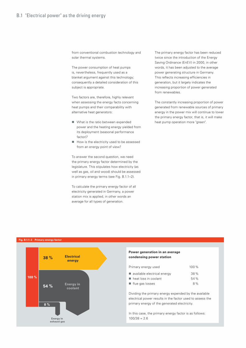
from conventional combustion technology and
solar thermal systems.
The power consumption of heat pumps
is, nevertheless, frequently used as a
blanket argument against this technology;
consequently a detailed consideration of this
subject is appropriate.
Two factors are, therefore, highly relevant
when assessing the energy facts concerning
heat pumps and their comparability with
alternative heat generators:
What is the ratio between expended
power and the heating energy yielded from
its deployment (seasonal performance
factor)?
How is the electricity used to be assessed
from an energy point of view?
To answer the second question, we need
the primary energy factor determined by the
legislature. This stipulates how electricity (as
well as gas, oil and wood) should be assessed
in primary energy terms (see Fig. B.1.1–2).
To calculate the primary energy factor of all
electricity generated in Germany, a power
station mix is applied, in other words an
average for all types of generation.
The primary energy factor has been reduced
twice since the introduction of the Energy
Saving Ordinance (EnEV) in 2000, in other
words, it has been adjusted to the average
power generating structure in Germany.
This reflects increasing efficiencies in
generation, but it largely indicates the
increasing proportion of power generated
from renewables.
The constantly increasing proportion of power
generated from renewable sources of primary
energy in the power mix will continue to lower
the primary energy factor, that is, it will make
heat pump operation more "green".
B.1 "Electrical power" as the driving energy
Fig. B.1.1–2 Primary energy factor
Power generation in an average
condensing power station
Primary energy used 100 %
available electrical energy 38 %
heat loss in coolant 54 %
flue gas losses 8 %
Dividing the primary energy expended by the available
electrical power results in the factor used to assess the
primary energy of the generated electricity.
In this case, the primary energy factor is as follows:
100/38 = 2.6
Electrical energy
Energy in exhaust gas
8 %
54 %
38 %
Energy in coolant
100 %
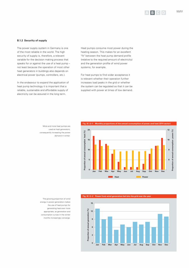
50/51
B.1.2 Security of supply
The power supply system in Germany is one
of the most reliable in the world. The high
security of supply is, therefore, a relevant
variable for the decision making process that
speaks for or against the use of a heat pump –
not least because the operation of most other
heat generators in buildings also depends on
electrical power (pumps, controllers, etc.).
In the endeavour to expand the application of
heat pump technology it is important that a
reliable, sustainable and affordable supply of
electricity can be assured in the long term.
Fig. B.1.2–1 Monthly proportions of the annual consumption of power and heat (EFH sector)
Fig. B.1.2–2 Power from wind generation fed into the grid over the year
Pro
po
rtio
n o
f an
nu
al c
on
sum
pti
on
hea
t (%
)
Pro
po
rtio
n o
f an
nu
al c
on
sum
pti
on
pow
er (
%)
Jan Feb Mar Apr May Jun Jul Aug Sep Oct Nov Dec0
10
5
15
20
8
6
10
12
Heat Power
Pro
po
rtio
n o
f an
nu
al g
ener
atio
n (
%)
Jan Feb Mar Apr May Jun Jul Aug Sep Oct Nov Dec0
6
9
3
12
15
The growing proportion of wind
energy in power generation makes
the use of heat pumps for
generating heat ever more
appropriate, as generation and
consumption curves in the winter
months increasingly converge.
More and more heat pumps are
used as heat generators,
consequently increasing the power
demand in winter.
Heat pumps consume most power during the
heating season. This makes for an excellent
"fit" between the heat pump demand profile
(relative to the required amount of electricity)
and the generation profile of wind power
systems, for example.
For heat pumps to find wider acceptance it
is relevant whether their operation further
increases load peaks in the grid or whether
the system can be regulated so that it can be
supplied with power at times of low demand.
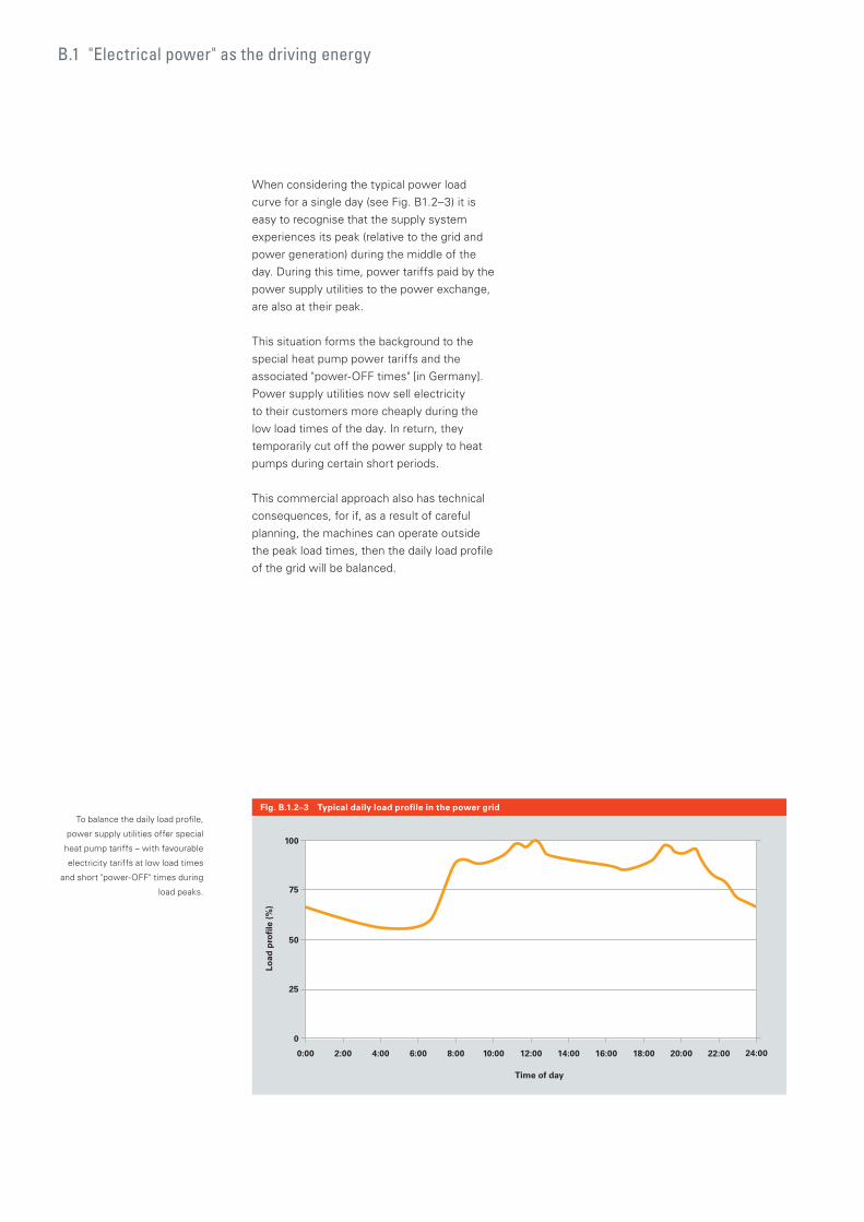
When considering the typical power load
curve for a single day (see Fig. B1.2–3) it is
easy to recognise that the supply system
experiences its peak (relative to the grid and
power generation) during the middle of the
day. During this time, power tariffs paid by the
power supply utilities to the power exchange,
are also at their peak.
This situation forms the background to the
special heat pump power tariffs and the
associated "power-OFF times" [in Germany].
Power supply utilities now sell electricity
to their customers more cheaply during the
low load times of the day. In return, they
temporarily cut off the power supply to heat
pumps during certain short periods.
This commercial approach also has technical
consequences, for if, as a result of careful
planning, the machines can operate outside
the peak load times, then the daily load profile
of the grid will be balanced.
Fig. B.1.2–3 Typical daily load profile in the power grid
0:00 2:00 4:00 6:00 8:00 10:00 12:00 14:00 16:00 18:00 20:00 22:00 24:00
75
50
25
0
100
Time of day
Load
pro
file
(%
)
To balance the daily load profile,
power supply utilities offer special
heat pump tariffs – with favourable
electricity tariffs at low load times
and short "power-OFF" times during
load peaks.
B.1 "Electrical power" as the driving energy

52/53
B.1.3 Smart metering
The rising proportion of power generated from
renewables in the power mix requires ever
more intelligent control of supply and demand.
Smart metering aims to advance this control
and to achieve the described "smoothing"
of the load profile in power consumption. In
addition, generation peaks from wind and
solar power should be brought to suitable
consumers in an appropriate way.
Now, smart metering ensures that the
power supply increasingly determines power
consumption and not – as happened until
recently – that supply follows demand. The
latter becomes increasingly difficult with
increasing generation capacity, particularly
from wind and solar power installations.
Heat pumps will play an ever more important
role in this complex and fundamental
restructuring of the power grid. There are
many consumers that, with little technical
effort, could be dovetailed into this system.
For example, freezers can be switched off for
several hours – insulation commonplace today
prevents any critical temperature increase.
Without intelligent load management it would
be pure coincidence whether an appliance
switches its load to the power grid during
peak times or not. However, if the appliance
"knows" that there is a glut of energy right
now, it could switch itself on. For freezers this
means that it lowers the internal temperature
a few degrees below the set value. This
provides a buffer for a longer period when no
power needs to be drawn.
Switching a heat pump follows a similar
pattern. Possible overshoots or undershoots
of the room temperature (during heating and
cooling), appropriate sizing of buffer cylinders
and a modulating operation, open up the
possibility of linking heat pumps efficiently
into an intelligent power grid.
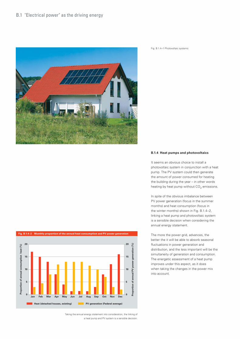
B.1.4 Heat pumps and photovoltaics
It seems an obvious choice to install a
photovoltaic system in conjunction with a heat
pump. The PV system could then generate
the amount of power consumed for heating
the building during the year – in other words
heating by heat pump without CO2 emissions.
In spite of the obvious imbalance between
PV power generation (focus in the summer
months) and heat consumption (focus in
the winter months) shown in Fig. B.1.4–2,
linking a heat pump and photovoltaic system
is a sensible decision when considering the
annual energy statement.
The more the power grid, advances, the
better the it will be able to absorb seasonal
fluctuations in power generation and
distribution, and the less important will be the
simultaneity of generation and consumption.
The energetic assessment of a heat pump
improves under this aspect, as it does
when taking the changes in the power mix
into account.
Fig. B.1.4–2 Monthly proportion of the annual heat consumption and PV power generation
Fig. B.1.4–1 Photovoltaic systems
Taking the annual energy statement into consideration, the linking of
a heat pump and PV system is a sensible decision.
Pro
po
rtio
n o
f an
nu
al c
on
sum
pti
on
hea
t (%
)
Pro
po
rtio
n o
f an
nu
al P
V p
ower
gen
erat
ion
(%
)
Jan Feb Mar Apr May Jun Jul Aug Sep Oct Nov Dec0
10
5
15
20
0
10
5
15
20
Heat (detached houses, existing) PV generation (Federal average)
B.1 "Electrical power" as the driving energy
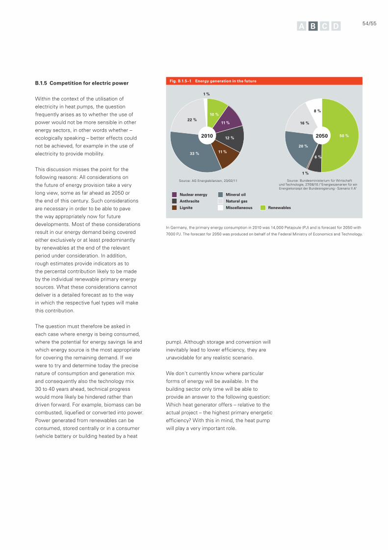
54/55
Source: Bundesministerium für Wirtschaft und Technologie, 27/08/10 / "Energieszenarien für einEnergiekonzept der Bundesregierung - Szenario II A"
Nuclear energy
Anthracite
Lignite
Mineral oil
Natural gas
Miscellaneous Renewables
Source: AG Energiebilanzen, 23/02/11
22 %
33 % 11 %
12 %
11 %
10 %
2010
8 %
16 %
20 %
1 %
6 %
50 %2050
1 %
B.1.5 Competition for electric power
Within the context of the utilisation of
electricity in heat pumps, the question
frequently arises as to whether the use of
power would not be more sensible in other
energy sectors, in other words whether –
ecologically speaking – better effects could
not be achieved, for example in the use of
electricity to provide mobility.
This discussion misses the point for the
following reasons: All considerations on
the future of energy provision take a very
long view, some as far ahead as 2050 or
the end of this century. Such considerations
are necessary in order to be able to pave
the way appropriately now for future
developments. Most of these considerations
result in our energy demand being covered
either exclusively or at least predominantly
by renewables at the end of the relevant
period under consideration. In addition,
rough estimates provide indicators as to
the percental contribution likely to be made
by the individual renewable primary energy
sources. What these considerations cannot
deliver is a detailed forecast as to the way
in which the respective fuel types will make
this contribution.
The question must therefore be asked in
each case where energy is being consumed,
where the potential for energy savings lie and
which energy source is the most appropriate
for covering the remaining demand. If we
were to try and determine today the precise
nature of consumption and generation mix
and consequently also the technology mix
30 to 40 years ahead, technical progress
would more likely be hindered rather than
driven forward. For example, biomass can be
combusted, liquefied or converted into power.
Power generated from renewables can be
consumed, stored centrally or in a consumer
(vehicle battery or building heated by a heat
pump). Although storage and conversion will
inevitably lead to lower efficiency, they are
unavoidable for any realistic scenario.
We don't currently know where particular
forms of energy will be available. In the
building sector only time will be able to
provide an answer to the following question:
Which heat generator offers – relative to the
actual project – the highest primary energetic
efficiency? With this in mind, the heat pump
will play a very important role.
Fig. B.1.5–1 Energy generation in the future
In Germany, the primary energy consumption in 2010 was 14,000 Petajoule (PJ) and is forecast for 2050 with
7000 PJ. The forecast for 2050 was produced on behalf of the Federal Ministry of Economics and Technology.
B.2 Statutory framework conditions
In Germany, the energy consumption of
buildings accounts for approximately 40 %
of total energy consumption. Consequently,
this sector is highly important to the energy-
political measures introduced by federal
and regional governments. As a result,
the German heating technology market
is increasingly influenced by statutory
framework conditions.
Statutory framework conditions
EnEV, Heating Act and Energy Label: The efficiency and linking of renewables in heat generation are also increasingly subject to statutory framework conditions. In this connection, heat pumps offer many benefits.
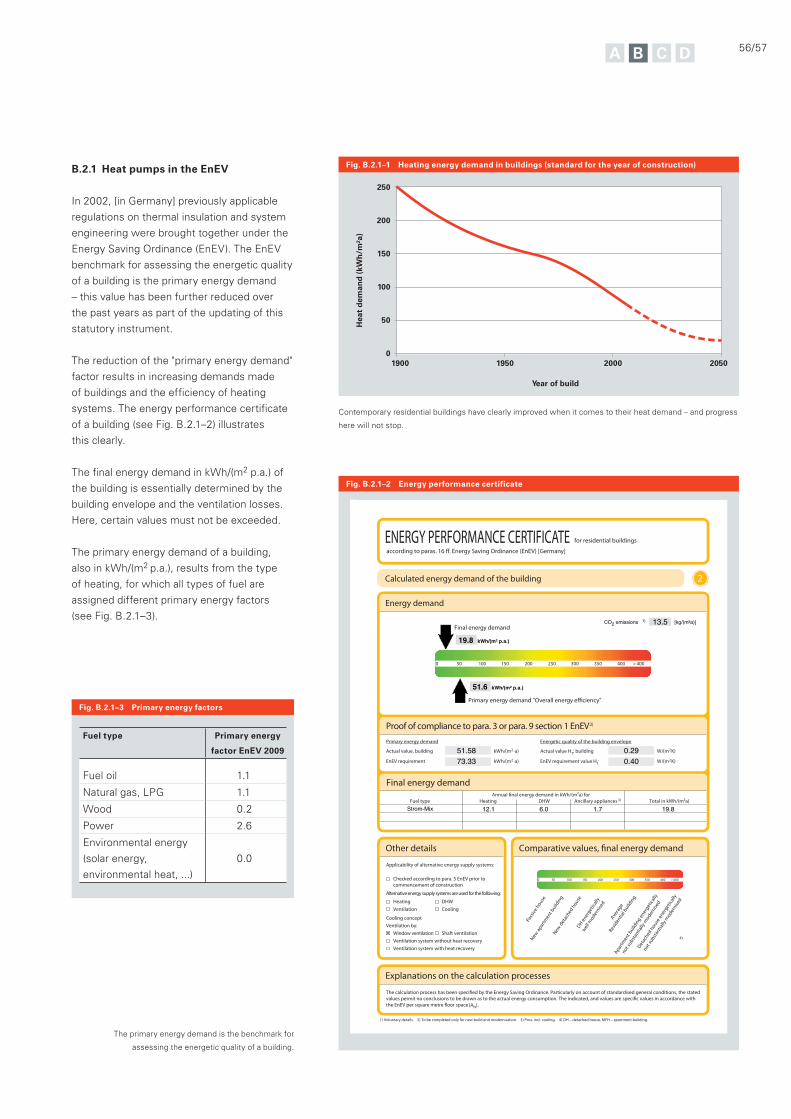
56/57
Fig. B.2.1–1 Heating energy demand in buildings (standard for the year of construction)
Fig. B.2.1–3 Primary energy factors
Hea
t d
eman
d (
kWh
/m²a
)
Year of build
1900
50
0
100
150
200
250
2000 20501950
B.2.1 Heat pumps in the EnEV
In 2002, [in Germany] previously applicable
regulations on thermal insulation and system
engineering were brought together under the
Energy Saving Ordinance (EnEV). The EnEV
benchmark for assessing the energetic quality
of a building is the primary energy demand
– this value has been further reduced over
the past years as part of the updating of this
statutory instrument.
The reduction of the "primary energy demand"
factor results in increasing demands made
of buildings and the efficiency of heating
systems. The energy performance certificate
of a building (see Fig. B.2.1–2) illustrates
this clearly.
The final energy demand in kWh/(m2 p.a.) of
the building is essentially determined by the
building envelope and the ventilation losses.
Here, certain values must not be exceeded.
The primary energy demand of a building,
also in kWh/(m2 p.a.), results from the type
of heating, for which all types of fuel are
assigned different primary energy factors
(see Fig. B.2.1–3).
Fuel type Primary energy
factor EnEV 2009
Fuel oil 1.1
Natural gas, LPG 1.1
Wood 0.2
Power 2.6
Environmental energy
(solar energy,
environmental heat, ...)
0.0
Contemporary residential buildings have clearly improved when it comes to their heat demand – and progress
here will not stop.
Fig. B.2.1–2 Energy performance certificate
2
Proof of compliance to para. 3 or para. 9 section 1 EnEV 2)
Final energy demand
Fuel type Heating DHW Ancillary appliances 3) Total in kWh/(m²a)
0 50 100 150 200 250 300 350 400 > 400
Other details
Applicability of alternative energy supply systems:
Checked according to para. 5 EnEV prior to
commencement of construction
Alternative energy supply systems are used for the following:
Heating DHW
Ventilation Cooling
Cooling conceptVentilation by:
Window ventilation Shaft ventilation
Ventilation system without heat recovery
Ventilation system with heat recovery
4)
0 50 100 150 200 250 300 350 400 > 400
Pass
ive
house
New
apar
tmen
t bui
ldin
g
N
ew d
etac
hed h
ouse
DH
ener
getic
ally
wel
l mod
ernis
ed
Ave
rage
Resi
dentia
l bui
ldin
g
Apar
tmen
t bui
ldin
g ener
getic
ally
not s
ubst
antia
lly m
oder
nised
D
etac
hed h
ouse
ener
getic
ally
not s
ubst
antia
lly m
oder
nised
Explanations on the calculation processes
tions, the stated
ccordance with
(AN).
1) Voluntary details. 2) To be completed only for new build and modernisation. 3) Poss. incl. cooling. 4) DH – detached house, MFH – apartment building.
Primary energy demand
m(/hWk Actual value, building 2·a)
m(/hWkEnEV requirement 2·a)
Energetic quality of the building envelope
Actual value HT, building m(/W 2K)
EnEV requirement value HT m(/W
’
2K)
Strom-Mix 12.1 6.0 1.7 19.8
51.6 kWh/(m² p.a.)
19.8 kWh/(m² p.a.)
CO2 emissions 1) 13.5
51.5873.33
0.290.40
[kg/(m²a)]
ENERGY PERFORMANCE CERTIFICATE for residential buildings
according to paras. 16 ff. Energy Saving Ordinance (EnEV) [Germany]
Calculated energy demand of the building
Energy demand
Final energy demand
Primary energy demand "Overall energy efficiency"
’
The primary energy demand is the benchmark for
assessing the energetic quality of a building.
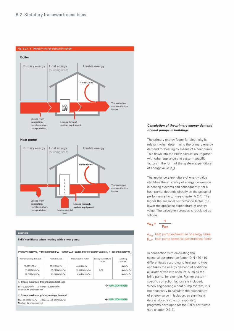
Primary energy
Losses from generation, transformation, transportation, ...
Losses through system equipment
Transmission and ventilation losses
Yields/Gains
Final energy (building limit)
Usable energy
Primary energy
Heat pump
Boiler
Yields/Gains
Final energy (building limit)
Usable energy
Losses from generation, transformation, transportation, ...
Losses through system equipment
Environmental heat
Transmission and ventilation losses
B.2 Statutory framework conditions
Calculation of the primary energy demand of heat pumps in buildings
The primary energy factor for electricity is
relevant when determining the primary energy
demand for heating by means of a heat pump.
This flows into the EnEV calculation, together
with other appliance and system-specific
factors in the form of the system expenditure
of energy value [ep].
The appliance expenditure of energy value
identifies the efficiency of energy conversion
in heating systems and consequently, for a
heat pump, depends directly on the seasonal
performance factor (see chapter A.2.4): The
higher the seasonal performance factor, the
lower the appliance expenditure of energy
value. The calculation process is regulated as
follows:
eH,g = 1
WP
eH,g heat pump expenditure of energy value
WP heat pump seasonal performance factor
In connection with calculating the
seasonal performance factor, DIN 4701-10
differentiates according to heat pump type
and takes the energy demand of additional
auxiliary drives into account, such as the
brine pump, for example. Further system-
specific correction factors are included.
When engineering a heat pump system, it is
not necessary to calculate the expenditure
of energy value in isolation, as significant
data is stored in the corresponding
programs developed for the EnEV certificate
(see chapter D.3.2).
EnEV certificate when heating with a heat pump:
Example
Fig. B.2.1–4 Primary energy demand to EnEV
Miscellaneous:
Primary energy Qp = (heat demand Qh + DHW Qw ) * expenditure of energy value e P
+ cooling energy QP,C
Primary energy demand Heat demand Domestic hot water Energy expenditure value
Cooling energy
10,811 kWh/a
33.43 kWh/(m²a)
10.70 kWh/(m³a)
11,398 kWh/a
35.24 kWh/(m²a)
11.28 kWh/(m³a)
4043 kWh/a
12.50 kWh/(m²a)
4.00 kWh/(m³a)
0.70
- kWh/a
- kWh/(m²a)
- kWh/(m³a)
1. Check maximum transmission heat loss
HT' = 0.26 W/(m²K) ≤ HT'max = 0.40 W/(m²K) No closer HT' check required
2. Check maximum primary energy demand
Qp = 33.43 kWh/(m²a) ≤ Qp,max = 70.63 kWh/(m²a) No closer Qp check required

58/59
B.2.2 Heat pumps in the
Renewable Energies Heat Act
[EEWärmeG]
The law to encourage the use of renewable
energy sources in the heating sector
(Renewable Energies Heat Act) effective
since the 1 January 2009, specifies a certain
proportion of renewables for the heating of
new buildings (in some federal states, similar
statutes also apply to building modernisation).
This act must be taken into account in addition
to the EnEV. If you decide in favour of heating
with a heat pump, this must provide at least
50 % of the required heating energy.
The Renewable Energies Heat Act specifies
certain minimum requirements concerning
the seasonal performance factor for the
appliances used. The obligation to use is
deemed to have been met if an air/water
or air/air heat pump achieves a calculated
seasonal performance factor of at least 3.5.
For all other types, a calculated seasonal
performance factor of at least 4 applies.
If the heat pump is also used for DHW
heating in the building, the required seasonal
performance factor is reduced by
0.2 percentage points respectively.
It may be necessary for systems that
incorporate a heat pump to be equipped with
a heat and electricity meter.
Practical experience over the past few years
has shown that heat pumps have developed
into one of the most efficient and affordable
solutions when it comes to the requirements
of the Renewable Energies Heat Act.
B.2.3 European framework directives
Like many other technology sectors, the
heating of buildings is also increasingly
determined by European directives which are
subsequently reflected in national statutes.
For example, the Germany EnEV is embedded
in the EU Directive 2002/91/EC on the overall
energy efficiency of buildings (EPBD = Energy
Performance of Buildings Directive).
In future, systems used for heating buildings
within the EU will also be subject to the
ErP (Energy related Products)/Eco Design
Directive 2009/125/EC. In future, an
increasing number of products will be labelled
in line with these new regulations, that should
provide consumers with better information on
energy efficiency. This method is already well
known from refrigerators and other domestic
appliances.
When this technical manual went to press no
final decision had been made as to how these
regulations would be implemented in detail
for heating systems. However, it is already
apparent that heat pumps will be added to the
best energy category.

B.3 Economic considerations
In most cases, heat pumps require an initial
high investment; ground sourced systems
can soon enter five figures. However, low
operating costs are the trade-off.
A professional consultation on viability
highlights what is important, and makes the
decision easier for owners.
Economic considerations
In addition to the undisputed positive ecological effects of a well sizedheat pump system, economic benefits also weigh in their favour.
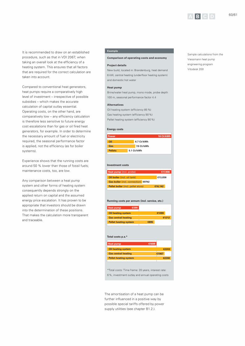
60/61
Sample calculations from the
Viessmann heat pump
engineering program
Vitodesk 200
Example
Comparison of operating costs and economy
Project details
New build, located in: Brandenburg, heat demand
6 kW, central heating (underfloor heating system)
and domestic hot water
Heat pump
Brine/water heat pump, mono mode, probe depth
100 m, seasonal performance factor 4.4
Alternatives
Oil heating system (efficiency 85 %)
Gas heating system (efficiency 90 %)
Pellet heating system (efficiency 90 %)
*Total costs: Time frame: 20 years, interest rate:
6 %, investment outlay and annual operating costs
It is recommended to draw on an established
procedure, such as that in VDI 2067, when
taking an overall look at the efficiency of a
heating system. This ensures that all factors
that are required for the correct calculation are
taken into account.
Compared to conventional heat generators,
heat pumps require a comparatively high
level of investment – irrespective of possible
subsidies – which makes the accurate
calculation of capital outlay essential.
Operating costs, on the other hand, are
comparatively low – any efficiency calculation
is therefore less sensitive to future energy
cost escalations than for gas or oil fired heat
generators, for example. In order to determine
the necessary amount of fuel or electricity
required, the seasonal performance factor
is applied, not the efficiency (as for boiler
systems).
Experience shows that the running costs are
around 50 % lower than those of fossil fuels;
maintenance costs, too, are low.
Any comparison between a heat pump
system and other forms of heating system
consequently depends strongly on the
applied return on capital and the assumed
energy price escalation. It has proven to be
appropriate that investors should be drawn
into the determination of these positions.
That makes the calculation more transparent
and traceable.
The amortisation of a heat pump can be
further influenced in a positive way by
possible special tariffs offered by power
supply utilities (see chapter B1.2.).
Investment costs
€17,906Heat pump (incl. probe)
€13,836Oil boiler (incl. oil tank)
Gas boiler (incl. connection)
Pellet boiler (incl. pellet store)
Running costs per annum (incl. service, etc.)
€9742
€16,142
Energy costs
Power
Oil
Gas
Pellets
6.7 Ct/kWh
7.0 Ct/kWh
5.1 Ct/kWh
16 Ct/kWh
Heat pump
Oil heating system
Gas central heating
Pellet heating system
€1099
€1212
€895
€599
Total costs p.a.*
Heat pump
Oil heating system
Gas central heating
Pellet heating system
€2203
€1967
€2200
€ 1699
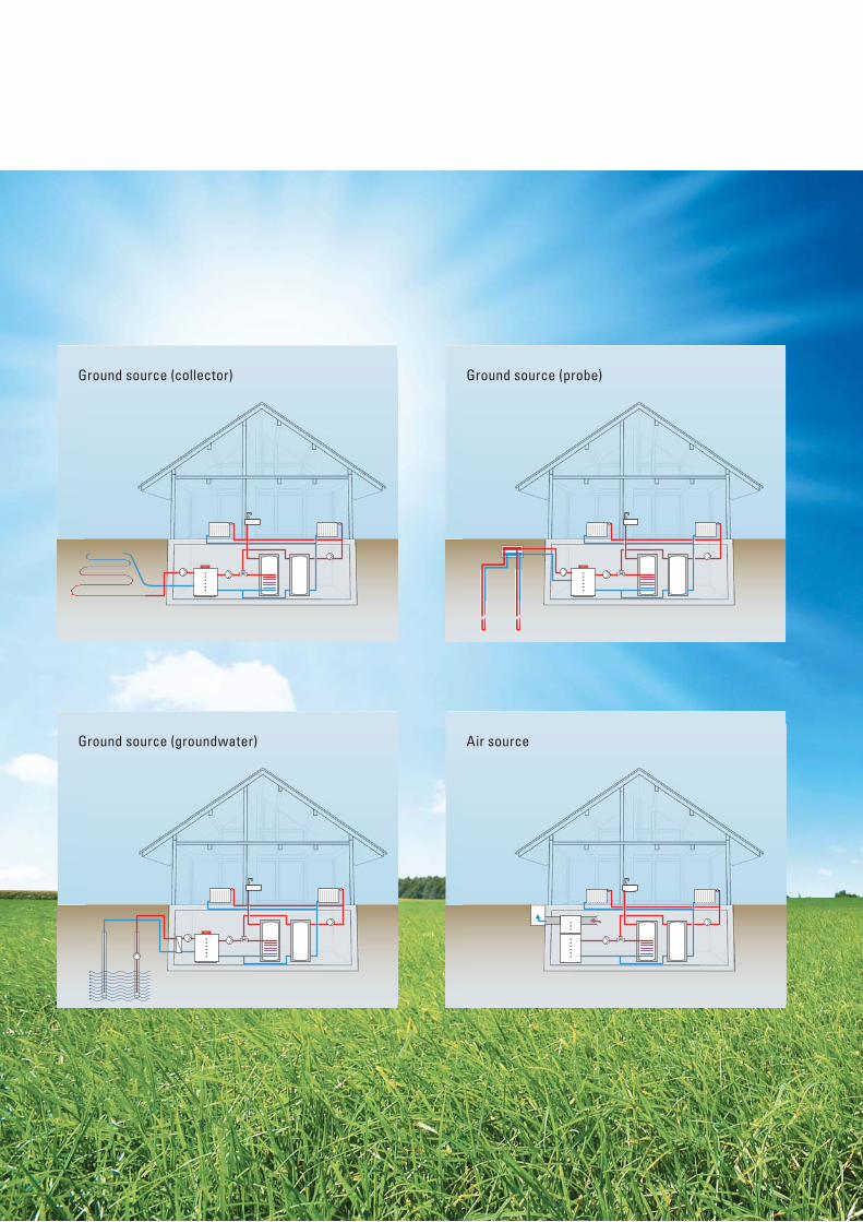
Ground source (probe)
Air source
Ground source (collector)
Ground source (groundwater)
62/63
water is available as a heat source. Air/water
heat pumps utilise outdoor air or extract air as
a primary source.
The following applies in every case – only
careful engineering and sizing of the primary
source can provide the basis for an efficient
heat pump system.
Different heat pump types are able to utilise
various primary sources. The decision as to
which heat source is most suitable depends
on local conditions.
Brine/water heat pumps use the ground as
primary energy source, either by deploying
geothermal collectors or geothermal probes.
Water/water heat pumps are used where
C Engineering and sizing the primary source
Chapter A describes the different energy sources available for use with heat pumps and their relative potential. The following chapter deals with the technical principles of developing these heat sources.
64 C.1 Brine/water heat pumps
65 C.1.1 Sizing the heat source
69 C.1.2 Heat transfer medium
70 C.1.3 Flow rate and pressure drop in the brine circuit
72 C.2 Water/water heat pumps
73 C.2.1 Groundwater
75 C.2.2 Coolant
76 C.3 Air/water heat pumps
77 C.3.1 Air/water heat pumps with unregulated compressor
77 C.3.2 Sizing/engineering
79 C.3.3 Acoustic engineering
82 C.3.4 Air routing for internally sited air/water heat pumps
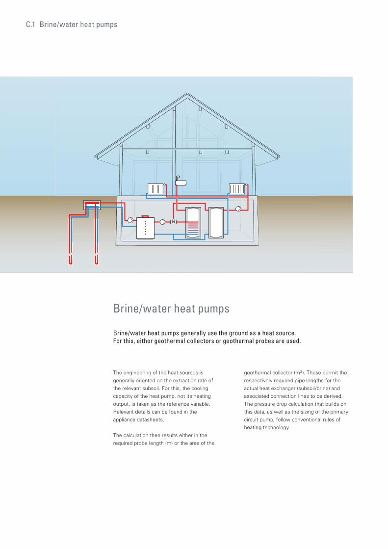
C.1 Brine/water heat pumps
Brine/water heat pumps
Brine/water heat pumps generally use the ground as a heat source. For this, either geothermal collectors or geothermal probes are used.
The engineering of the heat sources is
generally oriented on the extraction rate of
the relevant subsoil. For this, the cooling
capacity of the heat pump, not its heating
output, is taken as the reference variable.
Relevant details can be found in the
appliance datasheets.
The calculation then results either in the
required probe length (m) or the area of the
geothermal collector (m2). These permit the
respectively required pipe lengths for the
actual heat exchanger (subsoil/brine) and
associated connection lines to be derived.
The pressure drop calculation that builds on
this data, as well as the sizing of the primary
circuit pump, follow conventional rules of
heating technology.
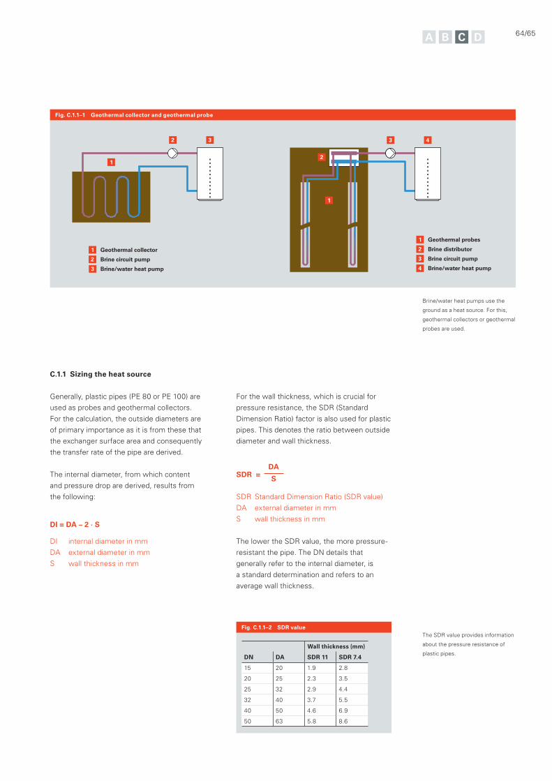
C.1.1 Sizing the heat source
Generally, plastic pipes (PE 80 or PE 100) are
used as probes and geothermal collectors.
For the calculation, the outside diameters are
of primary importance as it is from these that
the exchanger surface area and consequently
the transfer rate of the pipe are derived.
The internal diameter, from which content
and pressure drop are derived, results from
the following:
DI = DA – 2 · S
DI internal diameter in mm
DA external diameter in mm
S wall thickness in mm
Fig. C.1.1–1 Geothermal collector and geothermal probe
Fig. C.1.1–2 SDR value
3
2
1 Geothermal collector
Brine circuit pump
Brine/water heat pump3
3
2
1 Geothermal probes
Brine distributor
Brine circuit pump
Brine/water heat pump
3
4
42
12
1
64/65
For the wall thickness, which is crucial for
pressure resistance, the SDR (Standard
Dimension Ratio) factor is also used for plastic
pipes. This denotes the ratio between outside
diameter and wall thickness.
SDR = DA
S
SDR Standard Dimension Ratio (SDR value)
DA external diameter in mm
S wall thickness in mm
The lower the SDR value, the more pressure-
resistant the pipe. The DN details that
generally refer to the internal diameter, is
a standard determination and refers to an
average wall thickness.
The SDR value provides information
about the pressure resistance of
plastic pipes.Wall thickness (mm)
DN DA SDR 11 SDR 7.4
15 20 1.9 2.8
20 25 2.3 3.5
25 32 2.9 4.4
32 40 3.7 5.5
40 50 4.6 6.9
50 63 5.8 8.6
Brine/water heat pumps use the
ground as a heat source. For this,
geothermal collectors or geothermal
probes are used.
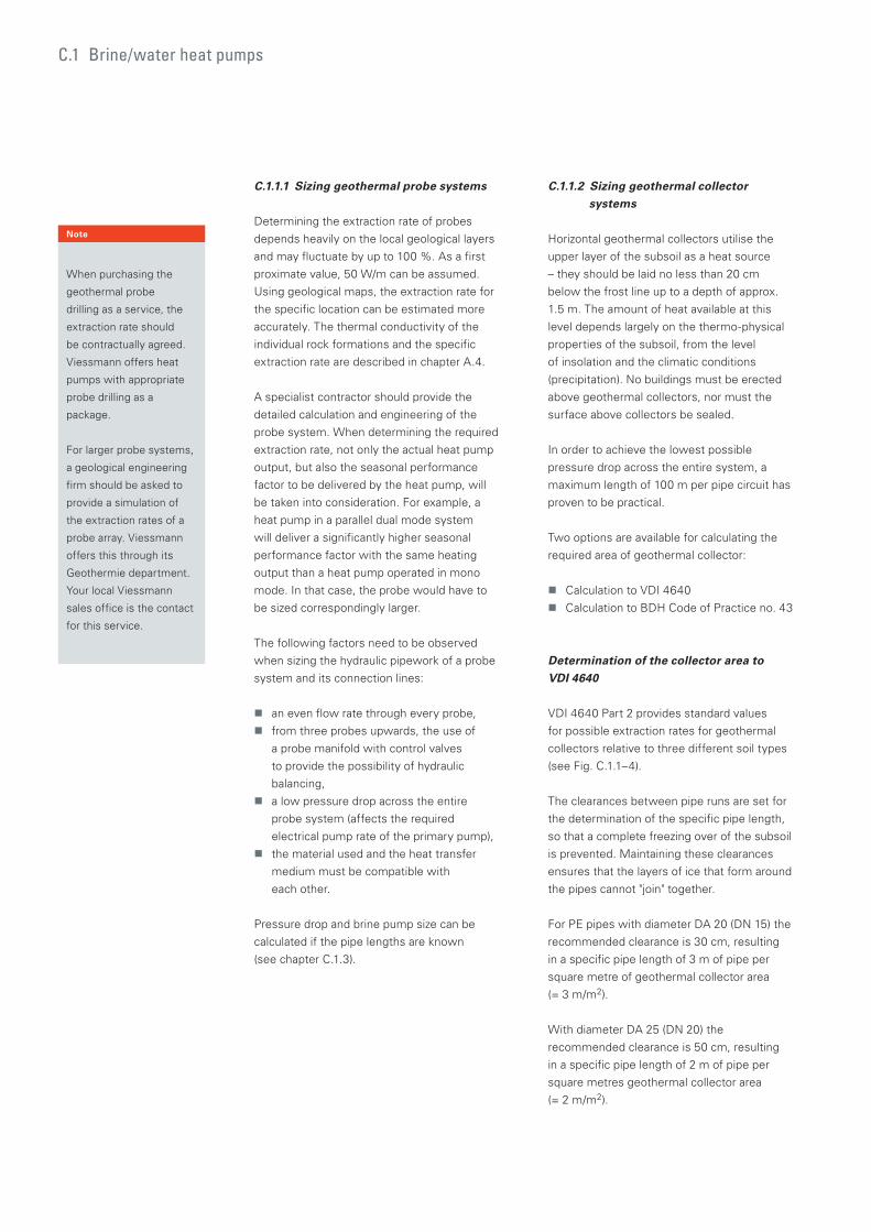
C.1 Brine/water heat pumps
C.1.1.1 Sizing geothermal probe systems
Determining the extraction rate of probes
depends heavily on the local geological layers
and may fluctuate by up to 100 %. As a first
proximate value, 50 W/m can be assumed.
Using geological maps, the extraction rate for
the specific location can be estimated more
accurately. The thermal conductivity of the
individual rock formations and the specific
extraction rate are described in chapter A.4.
A specialist contractor should provide the
detailed calculation and engineering of the
probe system. When determining the required
extraction rate, not only the actual heat pump
output, but also the seasonal performance
factor to be delivered by the heat pump, will
be taken into consideration. For example, a
heat pump in a parallel dual mode system
will deliver a significantly higher seasonal
performance factor with the same heating
output than a heat pump operated in mono
mode. In that case, the probe would have to
be sized correspondingly larger.
The following factors need to be observed
when sizing the hydraulic pipework of a probe
system and its connection lines:
an even flow rate through every probe,
from three probes upwards, the use of
a probe manifold with control valves
to provide the possibility of hydraulic
balancing,
a low pressure drop across the entire
probe system (affects the required
electrical pump rate of the primary pump),
the material used and the heat transfer
medium must be compatible with
each other.
Pressure drop and brine pump size can be
calculated if the pipe lengths are known
(see chapter C.1.3).
C.1.1.2 Sizing geothermal collector systems
Horizontal geothermal collectors utilise the
upper layer of the subsoil as a heat source
– they should be laid no less than 20 cm
below the frost line up to a depth of approx.
1.5 m. The amount of heat available at this
level depends largely on the thermo-physical
properties of the subsoil, from the level
of insolation and the climatic conditions
(precipitation). No buildings must be erected
above geothermal collectors, nor must the
surface above collectors be sealed.
In order to achieve the lowest possible
pressure drop across the entire system, a
maximum length of 100 m per pipe circuit has
proven to be practical.
Two options are available for calculating the
required area of geothermal collector:
Calculation to VDI 4640
Calculation to BDH Code of Practice no. 43
Determination of the collector area to VDI 4640
VDI 4640 Part 2 provides standard values
for possible extraction rates for geothermal
collectors relative to three different soil types
(see Fig. C.1.1–4).
The clearances between pipe runs are set for
the determination of the specific pipe length,
so that a complete freezing over of the subsoil
is prevented. Maintaining these clearances
ensures that the layers of ice that form around
the pipes cannot "join" together.
For PE pipes with diameter DA 20 (DN 15) the
recommended clearance is 30 cm, resulting
in a specific pipe length of 3 m of pipe per
square metre of geothermal collector area
(= 3 m/m2).
With diameter DA 25 (DN 20) the
recommended clearance is 50 cm, resulting
in a specific pipe length of 2 m of pipe per
square metres geothermal collector area
(= 2 m/m2).
Note
When purchasing the
geothermal probe
drilling as a service, the
extraction rate should
be contractually agreed.
Viessmann offers heat
pumps with appropriate
probe drilling as a
package.
For larger probe systems,
a geological engineering
firm should be asked to
provide a simulation of
the extraction rates of a
probe array. Viessmann
offers this through its
Geothermie department.
Your local Viessmann
sales office is the contact
for this service.
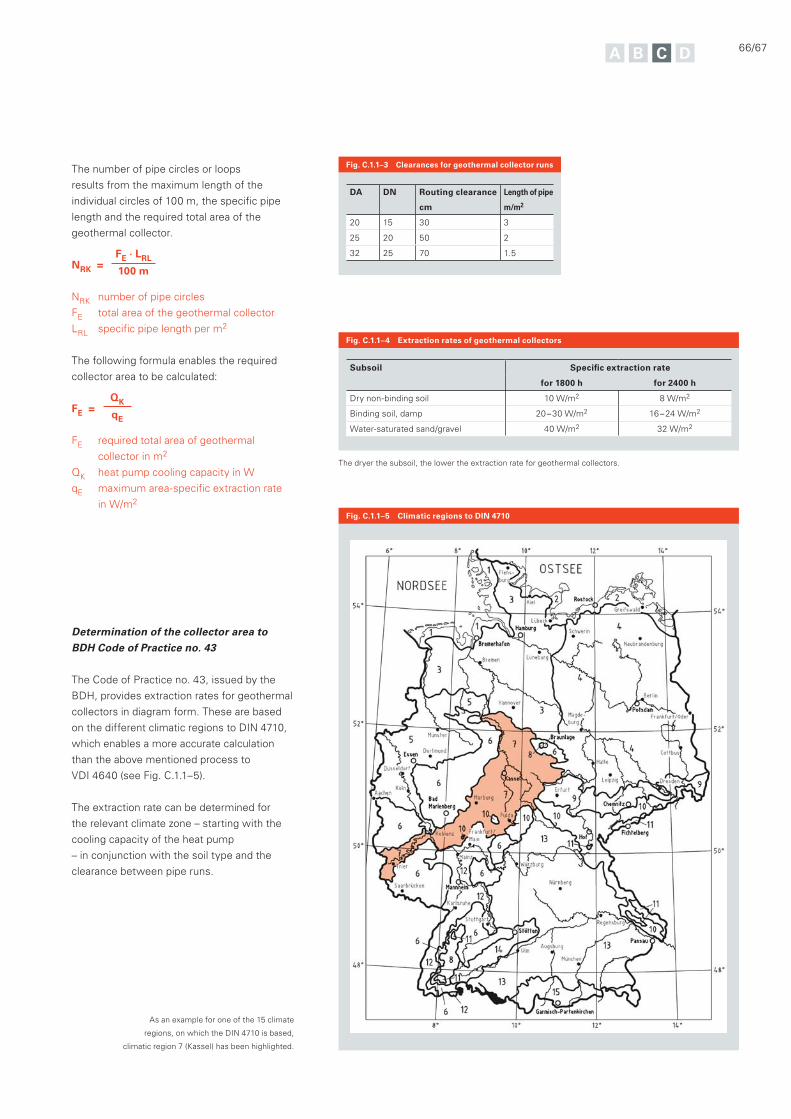
66/67
The number of pipe circles or loops
results from the maximum length of the
individual circles of 100 m, the specific pipe
length and the required total area of the
geothermal collector.
NRK = FE · LRL
100 m
NRK number of pipe circles
FE total area of the geothermal collector
LRL specific pipe length per m2
The following formula enables the required
collector area to be calculated:
FE = QK
qE
FE required total area of geothermal
collector in m2
QK heat pump cooling capacity in W
qE maximum area-specific extraction rate
in W/m2
The dryer the subsoil, the lower the extraction rate for geothermal collectors.
Fig. C.1.1–4 Extraction rates of geothermal collectors
Subsoil Specific extraction rate
for 1800 h for 2400 h
Dry non-binding soil 10 W/m2 8 W/m2
Binding soil, damp 20 – 30 W/m2 16 – 24 W/m2
Water-saturated sand/gravel 40 W/m2 32 W/m2
Fig. C.1.1–5 Climatic regions to DIN 4710
Determination of the collector area to BDH Code of Practice no. 43
The Code of Practice no. 43, issued by the
BDH, provides extraction rates for geothermal
collectors in diagram form. These are based
on the different climatic regions to DIN 4710,
which enables a more accurate calculation
than the above mentioned process to
VDI 4640 (see Fig. C.1.1–5).
The extraction rate can be determined for
the relevant climate zone – starting with the
cooling capacity of the heat pump
– in conjunction with the soil type and the
clearance between pipe runs.
As an example for one of the 15 climate
regions, on which the DIN 4710 is based,
climatic region 7 (Kassel) has been highlighted.
Fig. C.1.1–3 Clearances for geothermal collector runs
DA DN Routing clearance
cm
Length of pipe
m/m2
20 15 30 3
25 20 50 2
32 25 70 1.5
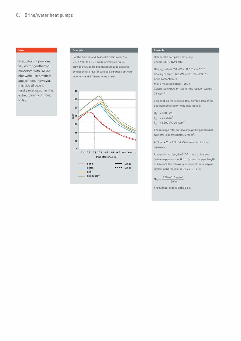
Note
In addition, it provides
values for geothermal
collectors with DA 32
pipework – in practical
applications, however,
this size of pipe is
hardly ever used, as it is
extraordinarily difficult
to lay.
Data for the compact heat pump
Vitocal 333-G BWT 108
Heating output: 7.8 kW (at B 0 °C / W 35 °C)
Cooling capacity: 6.3 kW (at B 0 °C / W 35 °C)
Brine content: 3.9 l
Mono mode operation (1800 h)
Calculated extraction rate for the location (sand):
25 W/m2
This enables the required total surface area of the
geothermal collector to be determined:
QK = 6300 W
qE = 25 W/m2
FE = 6300 W / 25 W/m2
The required total surface area of the geothermal
collector is approximately 250 m2.
A PE pipe 25 x 2.3 (DA 25) is selected for the
pipework.
At a maximum length of 100 m and a clearance
between pipe runs of 0.5 m (= specific pipe length
of 2 m/m2), the following number of required pipe
circles/loops results for DA 25 (DN 20):
NRK = 250 m2 · 2 m/m2
100 m
The number of pipe circles is 5.
For the area around Kassel (climatic zone 7 to
DIN 4710), the BDH Code of Practice no. 43
provides values for the maximum area-specific
extraction rate (qE) for various clearances between
pipe runs and different types of soil.
ExampleExample
C.1 Brine/water heat pumps
0.1 0.2 0.3 0.4 0.5 0.6 0.7 0.8 0.9 1
35
25
40
30
15
20
10
5
Pipe clearance (m)
W/m
2
Sand
Loam
Silt
Sandy clay
DA 20
DA 25
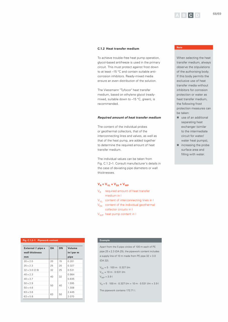
C.1.2 Heat transfer medium
To achieve trouble-free heat pump operation,
glycol-based antifreeze is used in the primary
circuit. This must protect against frost down
to at least –15 °C and contain suitable anti-
corrosion inhibitors. Ready-mixed media
ensure an even distribution of the solution.
The Viessmann "Tyfocor" heat transfer
medium, based on ethylene glycol (ready-
mixed, suitable down to –15 °C, green), is
recommended.
Required amount of heat transfer medium
The content of the individual probes
or geothermal collectors, that of the
interconnecting lines and valves, as well as
that of the heat pump, are added together
to determine the required amount of heat
transfer medium.
The individual values can be taken from
Fig. C.1.2–1. Consult manufacturer's details in
the case of deviating pipe diameters or wall
thicknesses.
VR = VVL + VEK + VWP
VR required amount of heat transfer
medium in l
VVL content of interconnecting lines in l
VEK content of the individual geothermal
collector circuits in l
VWP heat pump content in l
68/69
Note
When selecting the heat
transfer medium, always
observe the stipulations
of the authorising body.
If this body permits the
exclusive use of heat
transfer media without
inhibitors for corrosion
protection or water as
heat transfer medium,
the following frost
protection measures can
be taken:
use of an additional
separating heat
exchanger (similar
to the intermediate
circuit for water/
water heat pumps),
increasing the probe
surface area and
filling with water.
Apart from the 5 pipe circles of 100 m each of PE
pipe 25 x 2.3 (DA 25), the pipework content includes
a supply line of 10 m made from PE pipe 32 × 3.0
(DA 32).
VEK = 5 · 100 m · 0.327 l/m
VVL = 10 m · 0.531 l/m
VWP = 3.9 l
VR = 5 · 100 m · 0.327 l/m + 10 m · 0.531 l/m + 3.9 l
The pipework contains 172.71 l.
ExampleFig. C.1.2–1 Pipework content
External Ø pipe x
wall thickness
mm
DA DN Volume
in l per m
pipe
20 x 2.0 20 15 0.201
25 x 2.3 25 20 0.327
32 x 3.0 (2.9) 32 25 0.531
40 x 2.340 32
0.984
40 x 3.7 0.835
50 x 2.950 40
1.595
50 x 4.6 1.308
63 x 3.663 50
2.445
63 x 5.8 2.070
C.1.3 Flow rate and pressure drop in the
brine circuit
Apart from the system temperature in the
secondary circuit, sizing the heat source
system, including the pipework, is vital for
the efficiency of the heat pump system – this
concerns primarily the selection of the flow
rate in the primary circuit.
The lower the temperature differential in
the brine circuit, the higher the source
temperature at the evaporator – which in turn
increases the machine efficiency. For probes
and geothermal collectors, a temperature
differential of 3 K is recommended when
calculating the flow rate; up to 5 K is
permissible.
At 3 K, a mixture of 85 % water and 15 %
glycol and a flow rate in the brine circuit of
184 l/h per kW result.
This value underscores the importance of a
primary circuit pressure drop that is as low as
possible for overall system efficiency.
Where the total flow rate and the number of
probes or geothermal collectors are known,
the total pressure drop can be determined
using corresponding diagrams.
The total pressure drop results from adding
the pressure drop in the supply line and the
pressure drop in a parallel pipe circuit.
Δp = Δpsupply line + Δppipe circuit
Δp total pressure drop in mbar
Δpsupply line pressure drop in the supply line
in mbar
Δppipe circuit pressure drop in the pipe circuit
in mbar
Heat pump cooling capacity:
6.3 kW (with B 0 °C / W 35 °C)
Brine circuit flow rate = 6.3 kW · 184 l/(h · kW)
The total flow rate in the brine circuit is
approximately 1160 l/h.
Example
The total flow rate in the brine circuit is 1160 l/h.
With 5 pipe circles (parallel) of 100 m each PE pipe
25 x 2.3 (DA 25), the flow rate is therefore
1160/5 = 232 l/h
Supply line pressure drop:
10 m supply line PE pipe 32 × 3.0 (DA 32) with 1160 l/h
pressure drop per m: 3.0 mbar, total 30.0 mbar
Pipework pressure drop:
100 m PE pipe 25 x 2.3 (DA 25) with 232 l/h
pressure drop per m: 0.7 mbar, total 70.0 mbar
Δp = 70.0 mbar + 30.0 mbar
The total pressure drop is 100 mbar.
Example
For heat pumps with an integral brine
pump, the calculated pressure drop must be
compared to the permissible pressure drop of
the primary circuit to be connected. This detail
can be found in the datasheet.
For heat pumps without an integral brine
pump, the calculated pressure drop and flow
rate are used to size an external pump. For
this, the pressure drop on the evaporator side
of the heat pump must also be considered.
This information is also found in the
datasheet.
C.1 Brine/water heat pumps

70/71
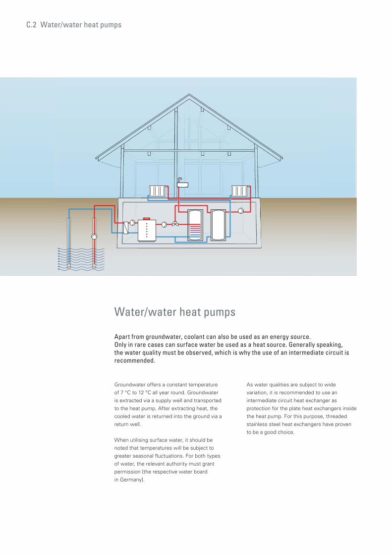
C.2 Water/water heat pumps
Groundwater offers a constant temperature
of 7 °C to 12 °C all year round. Groundwater
is extracted via a supply well and transported
to the heat pump. After extracting heat, the
cooled water is returned into the ground via a
return well.
When utilising surface water, it should be
noted that temperatures will be subject to
greater seasonal fluctuations. For both types
of water, the relevant authority must grant
permission [the respective water board
in Germany].
As water qualities are subject to wide
variation, it is recommended to use an
intermediate circuit heat exchanger as
protection for the plate heat exchangers inside
the heat pump. For this purpose, threaded
stainless steel heat exchangers have proven
to be a good choice.
Water/water heat pumps
Apart from groundwater, coolant can also be used as an energy source. Only in rare cases can surface water be used as a heat source. Generally speaking, the water quality must be observed, which is why the use of an intermediate circuit is recommended.
72/73
C.2.1 Groundwater
At least two wells are required when using
groundwater directly as a heat source.
Engineering and implementation of this well
system requires the services of a licensed
well contractor. Utilisation of groundwater
requires an official permit [in Germany].
Subject to correct engineering and
implementation, water/water heat pumps
can achieve very high seasonal performance
factors on account of their high primary
temperatures. However, when engineering,
various factors must be taken into
consideration:
Is sufficient groundwater available?
A volume of 250 l/h per kW heat pump
cooling capacity should be available
permanently; the pump rate should be
verified through a pump test.
The maximum temperature change must
not exceed +/– 6 K.
Observe the chemical composition and
quality of the groundwater (electrical
conductivity, oxygen, iron and manganese
content). Subject to the chemical
composition, there is a risk of corrosion for
pipework and system components, as well
as the risk of the supply and return wells
silting up.
A chemical analysis of the groundwater is
therefore recommended in every case.
The temperature differential in the primary
circuit is of great importance to water/water
heat pumps as it is for brine/water heat
pumps where the efficiency of the overall
system is concerned. On account of the
higher source temperature, for water as a
primary source, a flow rate based on a 3 K
temperature differential is recommended; 6 K
maximum is permissible.
This maximum value should never be
exceeded. For winter, a groundwater
temperature of 8 °C can be assumed, higher
temperature differentials could therefore
result in the heat exchanger freezing up.
Intermediate circuit
In currently available heat pumps, brazed plate
heat exchangers have established themselves
for transferring the heat from the primary to
the refrigerant circuit. These heat exchangers
are subjected to high energetic stresses and
they are in constant contact with the heat
source medium in the primary circuit. For
water/water heat pumps, the primary medium
is water in which the most divers chemical
constituents have dissolved. As mentioned
above, there is therefore a risk of corrosion
and sedimentation – with copper-brazed as
well as with stainless steel welded and nickel-
brazed plate heat exchangers.
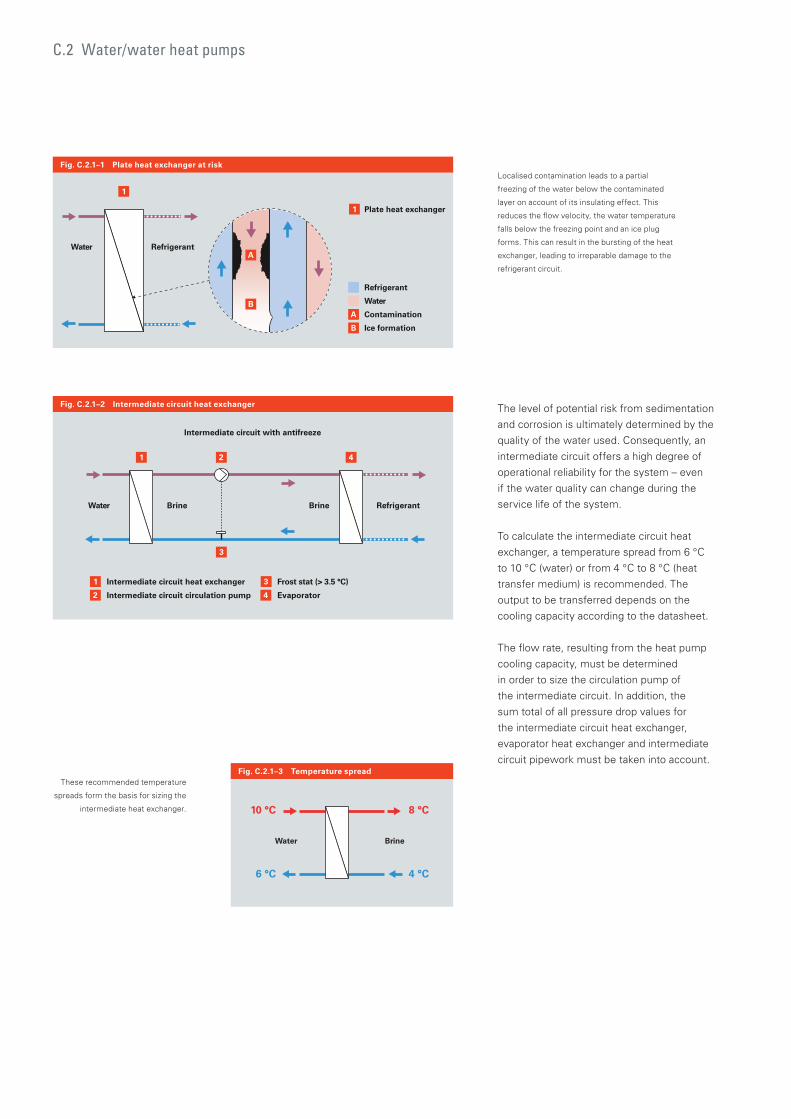
The level of potential risk from sedimentation
and corrosion is ultimately determined by the
quality of the water used. Consequently, an
intermediate circuit offers a high degree of
operational reliability for the system – even
if the water quality can change during the
service life of the system.
To calculate the intermediate circuit heat
exchanger, a temperature spread from 6 °C
to 10 °C (water) or from 4 °C to 8 °C (heat
transfer medium) is recommended. The
output to be transferred depends on the
cooling capacity according to the datasheet.
The flow rate, resulting from the heat pump
cooling capacity, must be determined
in order to size the circulation pump of
the intermediate circuit. In addition, the
sum total of all pressure drop values for
the intermediate circuit heat exchanger,
evaporator heat exchanger and intermediate
circuit pipework must be taken into account.
1
Refrigerant
Water
Contamination
Ice formation
A
B
B
RefrigerantWater
1
Plate heat exchanger
A
3
4
Brine Brine Refrigerant
Intermediate circuit with antifreeze
2
1
1 2
Intermediate circuit heat exchanger
Intermediate circuit circulation pump
Frost stat (> 3.5 °C)
Evaporator
4
3
Water
Fig. C.2.1–1 Plate heat exchanger at risk
Fig. C.2.1–2 Intermediate circuit heat exchanger
C.2 Water/water heat pumps
Fig. C.2.1–3 Temperature spread
6 °C
8 °C10 °C
4 °C
BrineWater
Localised contamination leads to a partial
freezing of the water below the contaminated
layer on account of its insulating effect. This
reduces the flow velocity, the water temperature
falls below the freezing point and an ice plug
forms. This can result in the bursting of the heat
exchanger, leading to irreparable damage to the
refrigerant circuit.
These recommended temperature
spreads form the basis for sizing the
intermediate heat exchanger.
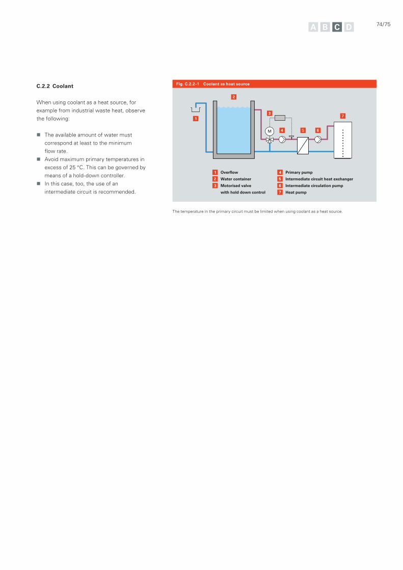
74/75
5
6
7
4
4 5 6
73
2
2
1
1
Overflow
Water container
Motorised valve
with hold down control
3
Primary pump
Intermediate circuit heat exchanger
Intermediate circulation pump
Heat pump
Fig. C.2.2–1 Coolant as heat sourceC.2.2 Coolant
When using coolant as a heat source, for
example from industrial waste heat, observe
the following:
The available amount of water must
correspond at least to the minimum
flow rate.
Avoid maximum primary temperatures in
excess of 25 °C. This can be governed by
means of a hold-down controller.
In this case, too, the use of an
intermediate circuit is recommended.
The temperature in the primary circuit must be limited when using coolant as a heat source.

C.3 Air/water heat pumps
Air/water heat pumps
Using air as a heat source requires the least effort of all. Air is drawn in, cooled in the heat pump evaporator and finally discharged again to the ambience.
Air as a primary source has two special
characteristics that must be observed when
planning the use of an air source heat pump;
these are explained in this chapter.
Firstly, it is warmer in summer than in winter.
This influences the heat pump's output and
efficiency. Secondly, the fans, that are an
essential part of the machine, generate noise
that must be acoustically assessed on-site.
76/77
C.3.1 Air/water heat pumps with
unregulated compressor
In the building heating sector, heat pumps are
used with output-controlled and uncontrolled
compressors.
Under certain operating conditions,
unregulated, so-called "fixed speed
compressors" achieve better seasonal
performance factors. At a constant source
temperature (for example extract air) or
when there is a high heat demand in summer
(for example for open air swimming pool
heating), the use of regulated compressors is
not compelling. However, heat pumps with
unregulated compressors for heating buildings
generally require a buffer cylinder in order to
be able to operate efficiently. For sizing such
cylinders, see chapter D.2.2.
C.3.2 Sizing/engineering
C.3.2.1 Heat pump output
When using air as a heat source, observe
that the heat pump heating output increases
with rising outside temperatures and drops
with falling outside temperatures. Mono
mode operation would consequently require
very large systems. This in turn would
mean that the heat pump was oversized
for the majority of its runtime. As a result,
air source heat pumps are predominantly
operated in dual mode. The dual mode point
should be between –3 °C and –10 °C outside
temperature so that the heat pump can cover
the largest possible proportion of the annual
heat load (see chapter D).
Ideally, the heat load of the building will be
covered closely by the heat pump at the given
standard outside temperature. Although the
output stages of Viessmann heat pumps are
very close to each other, an "accurate" sizing
of the machine is only rarely possible. In other
words, the available outputs will, in most
cases, lie either above or below the heat load.
When selecting a suitable heat pump, initially
the model, the output of which lies below
the heat load of the building, will be chosen.
A simulation determines the proportion of
reheating of the required annual heat load.
DIN EN 15450 limits electrical reheating to a
maximum of 5 %. If the result lies below that
value, that heat pump can continue to be used
for planning purposes.
A simulation program assists in the calculation
Heat load of the building: 15 kW
Standard outside temperature: –14 °C
System temperatures: 45/35 °C
The simulation of a 14 kW heat pump delivers a
proportion of electrical reheating (heating rod) on
the annual heat load of 2 %.
Example
of the necessary output of any electrical
reheater. The output diagram of a heat pump
can be used to explain the calculation path.
Here, the output is shown subject to source
and flow temperature.
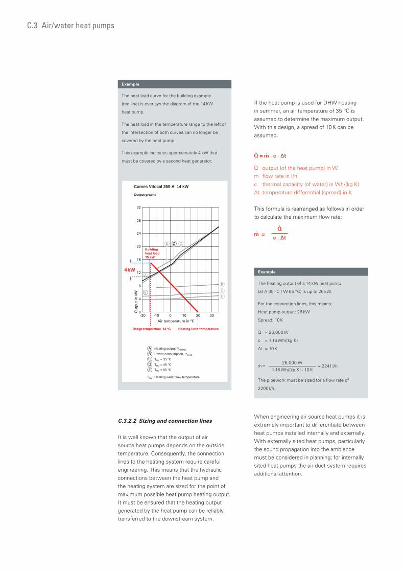
C.3 Air/water heat pumps
If the heat pump is used for DHW heating
in summer, an air temperature of 35 °C is
assumed to determine the maximum output.
With this design, a spread of 10 K can be
assumed.
= · c · Δt
output (of the heat pump) in W
flow rate in l/h
c thermal capacity (of water) in Wh/(kg K)
Δt temperature differential (spread) in K
This formula is rearranged as follows in order
to calculate the maximum flow rate:
= c · Δt
When engineering air source heat pumps it is
extremely important to differentiate between
heat pumps installed internally and externally.
With externally sited heat pumps, particularly
the sound propagation into the ambience
must be considered in planning; for internally
sited heat pumps the air duct system requires
additional attention.
The heat load curve for the building example
(red line) is overlays the diagram of the 14 kW
heat pump.
The heat load in the temperature range to the left of
the intersection of both curves can no longer be
covered by the heat pump.
This example indicates approximately 4 kW that
must be covered by a second heat generator.
Example
Curves Vitocal 350-A 14 kW
Output graphs
02002- 030101-0
4
8
12
16
20
24
Ou
tpu
t in
kW
Air temperature in °C
28
32
Heating output Pheating
Power consumption, Pelectr.
THV = 35 °CTHV = 45 °CTHV = 65 °C
THV Heating water flow temperature
4kW
Design temperature -14 °C Heating limit temperature
Buildingheat load 15 kW
The heating output of a 14 kW heat pump
(at A 35 °C / W 65 °C) is up to 26 kW.
For the connection lines, this means:
Heat pump output: 26 kW
Spread: 10 K
= 26,000 W
c = 1.16 Wh/(kg·K)
Δt = 10 K
= 26,000 W
= 2241 l/h1.16 Wh/(kg·K) · 10 K
The pipework must be sized for a flow rate of
2200 l/h.
Example
C.3.2.2 Sizing and connection lines
It is well known that the output of air
source heat pumps depends on the outside
temperature. Consequently, the connection
lines to the heating system require careful
engineering. This means that the hydraulic
connections between the heat pump and
the heating system are sized for the point of
maximum possible heat pump heating output.
It must be ensured that the heating output
generated by the heat pump can be reliably
transferred to the downstream system.
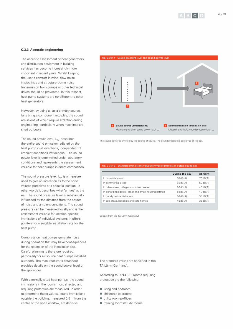
78/79
Extract from the TA Lärm [Germany]
During the day At night
In industrial areas 70 dB(A) 70 dB(A)
In commercial areas 65 dB(A) 50 dB(A)
In urban areas, villages and mixed areas 60 dB(A) 45 dB(A)
In general residential areas and small housing estates 55 dB(A) 40 dB(A)
In purely residential areas 50 dB(A) 35 dB(A)
In spa areas, hospitals and care homes 45 dB(A) 35 dB(A)
C.3.3 Acoustic engineering
The acoustic assessment of heat generators
and distribution equipment in building
services has become increasingly more
important in recent years. Whilst keeping
the user's comfort in mind, flow noise
in pipelines and structure-borne noise
transmission from pumps or other technical
drives should be prevented. In this respect,
heat pump systems are no different to other
heat generators.
However, by using air as a primary source,
fans bring a component into play, the sound
emissions of which require attention during
engineering, particularly when machines are
sited outdoors.
The sound power level, LW, describes
the entire sound emission radiated by the
heat pump in all directions, independent of
ambient conditions (reflections). The sound
power level is determined under laboratory
conditions and represents the assessment
variable for heat pumps in direct comparison.
The sound pressure level, LP, is a measure
used to give an indication as to the noise
volume perceived at a specific location. In
other words it describes what "arrives" at the
ear. The sound pressure level is substantially
influenced by the distance from the source
of noise and ambient conditions. The sound
pressure can be measured locally and is the
assessment variable for location-specific
immissions of individual systems. It offers
pointers for a suitable installation site for the
heat pump.
Compression heat pumps generate noise
during operation that may have consequences
for the selection of the installation site.
Careful planning is therefore required,
particularly for air source heat pumps installed
outdoors. The manufacturer's datasheet
provides details on the sound power level of
the appliances.
With externally sited heat pumps, the sound
immissions in the rooms most affected and
requiring protection are measured. In order
to determine these values, sound immissions
outside the building, measured 0.5 m from the
centre of the open window, are decisive.
Fig. C.3.3–1 Sound pressure level and sound power level
Fig. C.3.3–2 Standard immissions values for type of immission outside buildings
2
2
1
1
Sound source (emission site)
Measuring variable: sound power level LW
Sound immission (immission site)
Measuring variable: sound pressure level LP
The sound power is emitted by the source of sound. The sound pressure is perceived at the ear.
The standard values are specified in the
TA Lärm [Germany].
According to DIN 4109, rooms requiring
protection are the following:
living and bedroom
children's bedrooms
utility rooms/offices
training rooms/study rooms
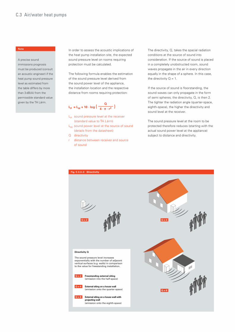
In order to assess the acoustic implications of
the heat pump installation site, the expected
sound pressure level on rooms requiring
protection must be calculated.
The following formula enables the estimation
of the sound pressure level derived from
the sound power level of the appliance,
the installation location and the respective
distance from rooms requiring protection:
LP = LW + 10 · log (Q
)4 · π · r2
LP sound pressure level at the receiver
(standard value to TA Lärm)
LW sound power level at the source of sound
(details from the datasheet)
Q directivity
r distance between receiver and source
of sound
Fig. C.3.3–3 Directivity
C.3 Air/water heat pumps
The directivity, Q, takes the spacial radiation
conditions at the source of sound into
consideration. If the source of sound is placed
in a completely unobstructed room, sound
waves propagate in the air in every direction
equally in the shape of a sphere. In this case,
the directivity Q = 1.
If the source of sound is floorstanding, the
sound waves can only propagate in the form
of semi spheres; the directivity, Q, is then 2.
The tighter the radiation angle (quarter-space,
eighth-space), the higher the directivity and
sound level at the receiver.
The sound pressure level at the room to be
protected therefore reduces (starting with the
actual sound power level at the appliance)
subject to distance and directivity.
Freestanding external siting (emission into the half-space)
Q = 2
External siting on a house wall(emission onto the quarter-space)
Q = 4
External siting on a house wall with projecting wall (emission onto the eighth-space)
Q = 8
Directivity Q
The sound pressure level increases exponentially with the number of adjacent vertical surfaces (e.g. walls) in comparison to the value for freestanding installation.
Q = 2 Q = 4
Q = 8
Note
A precise sound
immissions prognosis
must be produced (consult
an acoustic engineer) if the
heat pump sound pressure
level as estimated from
the table differs by more
than 3 dB(A) from the
permissible standard value
given by the TA Lärm.
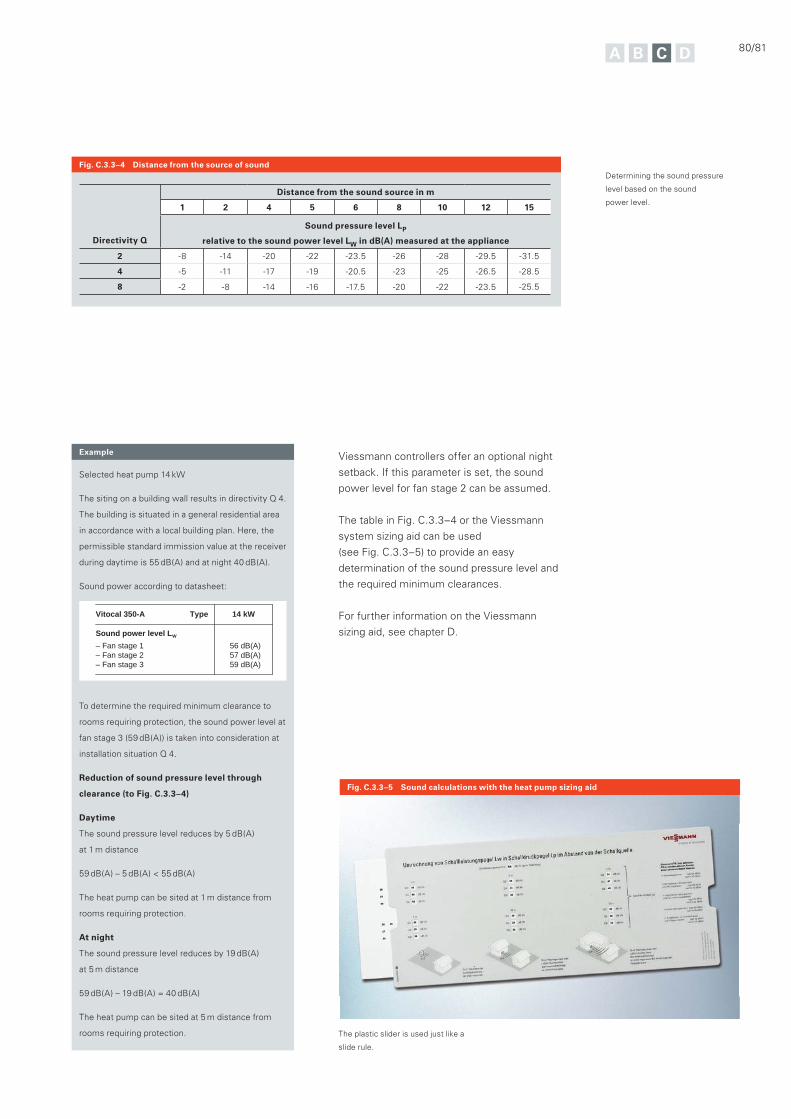
80/81
Fig. C.3.3–4 Distance from the source of sound
Directivity Q
Distance from the sound source in m
1 2 4 5 6 8 10 12 15
Sound pressure level LP
relative to the sound power level LW in dB(A) measured at the appliance
2 -8 -14 -20 -22 -23.5 -26 -28 -29.5 -31.5
4 -5 -11 -17 -19 -20.5 -23 -25 -26.5 -28.5
8 -2 -8 -14 -16 -17.5 -20 -22 -23.5 -25.5
Determining the sound pressure
level based on the sound
power level.
Selected heat pump 14 kW
The siting on a building wall results in directivity Q 4.
The building is situated in a general residential area
in accordance with a local building plan. Here, the
permissible standard immission value at the receiver
during daytime is 55 dB(A) and at night 40 dB(A).
Sound power according to datasheet:
To determine the required minimum clearance to
rooms requiring protection, the sound power level at
fan stage 3 (59 dB(A)) is taken into consideration at
installation situation Q 4.
Reduction of sound pressure level through
clearance (to Fig. C.3.3–4)
Daytime
The sound pressure level reduces by 5 dB(A)
at 1 m distance
59 dB(A) – 5 dB(A) < 55 dB(A)
The heat pump can be sited at 1 m distance from
rooms requiring protection.
At night
The sound pressure level reduces by 19 dB(A)
at 5 m distance
59 dB(A) – 19 dB(A) = 40 dB(A)
The heat pump can be sited at 5 m distance from
rooms requiring protection.
Example
Type 14 kWVitocal 350-A
Sound power level LW
– Fan stage 1– Fan stage 2– Fan stage 3
56 dB(A)57 dB(A)59 dB(A)
Viessmann controllers offer an optional night
setback. If this parameter is set, the sound
power level for fan stage 2 can be assumed.
The table in Fig. C.3.3–4 or the Viessmann
system sizing aid can be used
(see Fig. C.3.3–5) to provide an easy
determination of the sound pressure level and
the required minimum clearances.
For further information on the Viessmann
sizing aid, see chapter D.
Fig. C.3.3–5 Sound calculations with the heat pump sizing aid
The plastic slider is used just like a
slide rule.
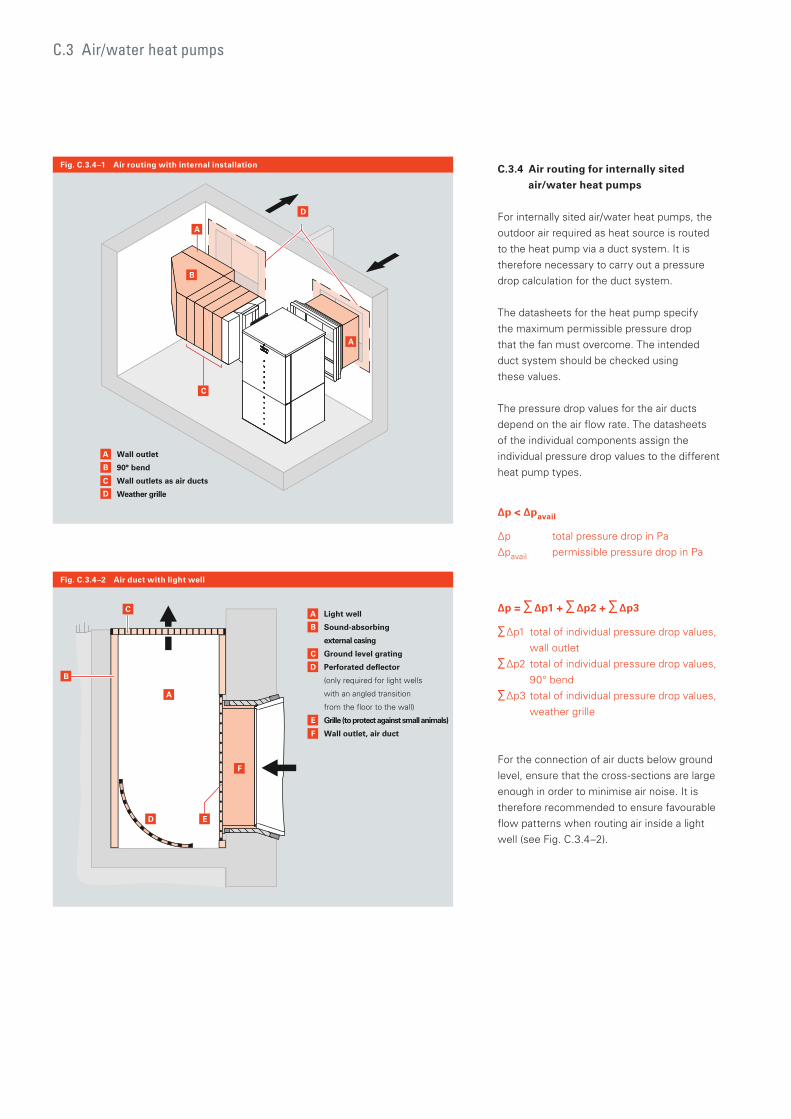
C.3.4 Air routing for internally sited
air/water heat pumps
For internally sited air/water heat pumps, the
outdoor air required as heat source is routed
to the heat pump via a duct system. It is
therefore necessary to carry out a pressure
drop calculation for the duct system.
The datasheets for the heat pump specify
the maximum permissible pressure drop
that the fan must overcome. The intended
duct system should be checked using
these values.
The pressure drop values for the air ducts
depend on the air flow rate. The datasheets
of the individual components assign the
individual pressure drop values to the different
heat pump types.
Δp < Δpavail
Δp total pressure drop in Pa
Δpavail permissible pressure drop in Pa
Δp = ∑ Δp1 + ∑ Δp2 + ∑ Δp3
∑ Δp1 total of individual pressure drop values,
wall outlet
∑ Δp2 total of individual pressure drop values,
90° bend
∑ Δp3 total of individual pressure drop values,
weather grille
For the connection of air ducts below ground
level, ensure that the cross-sections are large
enough in order to minimise air noise. It is
therefore recommended to ensure favourable
flow patterns when routing air inside a light
well (see Fig. C.3.4–2).
C.3 Air/water heat pumps
C
A
A
B
D
B
A Wall outlet
90° bend
Wall outlets as air ducts
Weather grille
C
D
B
A Light well
Sound-absorbing
external casing
Ground level grating
Perforated deflector
(only required for light wells
with an angled transition
from the floor to the wall)
Grille (to protect against small animals)
Wall outlet, air duct
C
D
F
E
D
C
A
F
B
E
Fig. C.3.4–1 Air routing with internal installation
Fig. C.3.4–2 Air duct with light well
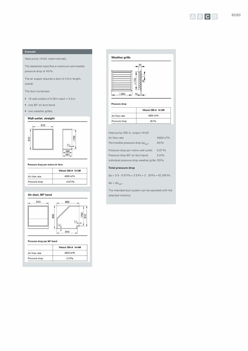
82/83
Heat pump 350-A, output 14 kW
Air flow rate 4000 m3/h
Permissible pressure drop Δpverf 45 Pa
Pressure drop per metre wall outlet: 0.07 Pa
Pressure drop 90° air duct bend: 2.0 Pa
individual pressure drop weather grille: 20 Pa
Total pressure drop
Δp = 3.5 · 0.07 Pa + 2.0 Pa + 2 · 20 Pa = 42.245 Pa
Δp < Δpverf
The intended duct system can be operated with the
selected machine.
Heat pump 14 kW, sited internally.
The datasheet specifies a maximum permissible
pressure drop of 45 Pa.
The air supply requires a duct of 3.5 m length,
overall.
The duct comprises:
10 wall outlets of 0.35 m each = 3.5 m
one 90° air duct bend
two weather grilles
Example
84/85
This chapter provides design engineers and
heating system installers with information that
is important for the correct selection of
appliances and determination of conditions, in
order to be able to significantly influence the
efficiency of the overall system on the heat
transfer side. At the end of this chapter
Viessmann engineering aids for trade partners
are explained in full.
In building services, efficiency is achieved
through optimum interaction between all
components employed. Given this pre-
requisite, it is essential that the engineering
and layout of a heating system meet the three
following requirements: user convenience,
reliable operation and the lowest possible use
of primary and auxiliary energy.
86 D.1 Operating modes
87 D.1.1 Mono mode operation
87 D.1.2 Dual mode operation
89 D.1.3 Cascade systems
90 D.1.4 Combination with renewables
92 D.2 Secondary circuit
93 D.2.1 DHW heating
106 D.2.2 Heating operation
111 D.2.3 Cooling
116 D.3 Output calculation and engineering aids
117 D.3.1 Determining the heat pump output
118 D.3.2 Sizing aids for heat pump systems
D System engineering
Whilst the previous chapter considered the different energy sources available for use with heat pumps, this chapter turns its attention to the way that heat pumps interact with other components. Only carefully devised planning and engineering turns efficient appliances into efficient systems.
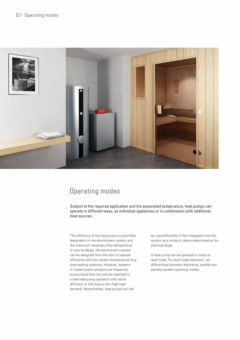
D.1 Operating modes
The efficiency of the heat pump is essentially
dependent on the downstream system and
the maximum necessary flow temperature.
In new buildings, the downstream system
can be designed from the start to operate
efficiently with low system temperatures (e.g.
area heating systems). However, systems
in modernisation projects are frequently
encountered that can only be matched to
a sole heat pump operation with some
difficulty, or that have a very high heat
demand. Nevertheless, heat pumps can still
Operating modes
Subject to the required application and the associated temperature, heat pumps can operate in different ways, as individual appliances or in combination with additional heat sources.
be used efficiently if their integration into the
system as a whole is clearly determined at the
planning stage.
A heat pump can be operated in mono or
dual mode. For dual mode operation, we
differentiate between alternative, parallel and
partially parallel operating modes.
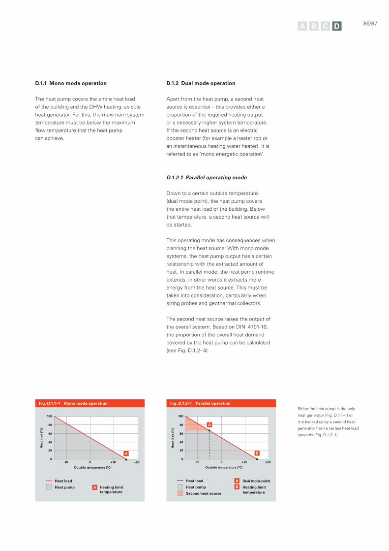
86/87
Fig. D.1.1–1 Mono mode operation Fig. D.1.2–1 Parallel operation
D.1.1 Mono mode operation
The heat pump covers the entire heat load
of the building and the DHW heating, as sole
heat generator. For this, the maximum system
temperature must be below the maximum
flow temperature that the heat pump
can achieve.
-10 0
Outside temperature (°C)
Hea
t lo
ad (
%)
+10 +20
100
80
60
40
20
0
Heat load
Heat pump A Heating limit temperature
A
Heat load
Heat pump
Second heat source
A
B
Dual mode point
Heating limit temperature
-10 0
Outside temperature (°C)
Hea
t lo
ad (
%)
+10 +20
100
80
60
40
20
0
A
B
D.1.2 Dual mode operation
Apart from the heat pump, a second heat
source is essential – this provides either a
proportion of the required heating output
or a necessary higher system temperature.
If the second heat source is an electric
booster heater (for example a heater rod or
an instantaneous heating water heater), it is
referred to as "mono energetic operation".
D.1.2.1 Parallel operating mode
Down to a certain outside temperature
(dual mode point), the heat pump covers
the entire heat load of the building. Below
that temperature, a second heat source will
be started.
This operating mode has consequences when
planning the heat source: With mono mode
systems, the heat pump output has a certain
relationship with the extracted amount of
heat. In parallel mode, the heat pump runtime
extends, in other words it extracts more
energy from the heat source. This must be
taken into consideration, particularly when
sizing probes and geothermal collectors.
The second heat source raises the output of
the overall system. Based on DIN 4701-10,
the proportion of the overall heat demand
covered by the heat pump can be calculated
(see Fig. D.1.2–4).
Either the heat pump is the only
heat generator (Fig. D.1.1–1) or
it is backed up by a second heat
generator from a certain heat load
upwards (Fig. D.1.2–1).
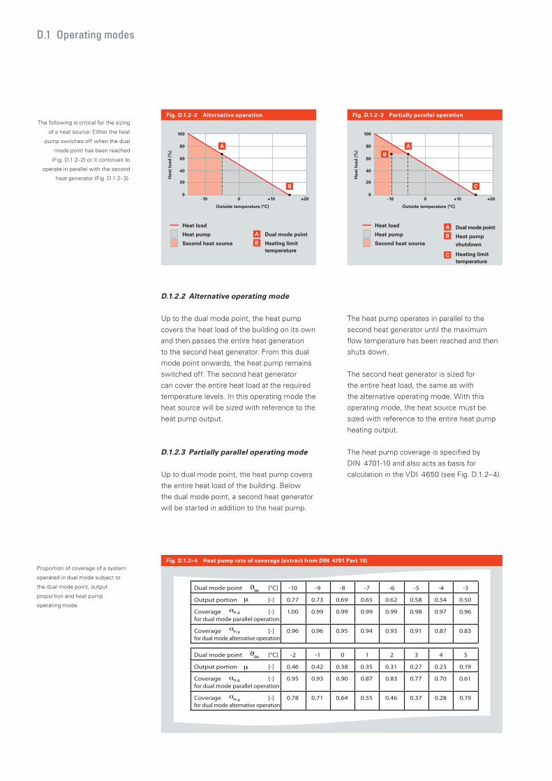
D.1 Operating modes
D.1.2.2 Alternative operating mode
Up to the dual mode point, the heat pump
covers the heat load of the building on its own
and then passes the entire heat generation
to the second heat generator. From this dual
mode point onwards, the heat pump remains
switched off. The second heat generator
can cover the entire heat load at the required
temperature levels. In this operating mode the
heat source will be sized with reference to the
heat pump output.
D.1.2.3 Partially parallel operating mode
Up to dual mode point, the heat pump covers
the entire heat load of the building. Below
the dual mode point, a second heat generator
will be started in addition to the heat pump.
The heat pump operates in parallel to the
second heat generator until the maximum
flow temperature has been reached and then
shuts down.
The second heat generator is sized for
the entire heat load, the same as with
the alternative operating mode. With this
operating mode, the heat source must be
sized with reference to the entire heat pump
heating output.
The heat pump coverage is specified by
DIN 4701-10 and also acts as basis for
calculation in the VDI 4650 (see Fig. D.1.2–4).
Fig. D.1.2–2 Alternative operation Fig. D.1.2–3 Partially parallel operation
Heat load
Heat pump
Second heat source
-10 0
Outside temperature (°C)
Hea
t lo
ad (
%)
+10 +20
100
80
60
40
20
0
A
B
Dual mode point
Heating limit temperature
A
B
Heat load
Heat pump
Second heat source
-10 0
Outside temperature (°C)
+10 +20
B
A
B
C
Dual mode point
Heat pump
shutdown
Heating limit temperature
A
C
Hea
t lo
ad (
%)
100
80
60
40
20
0
Fig. D.1.2–4 Heat pump rate of coverage (extract from DIN 4701 Part 10)
The following is critical for the sizing
of a heat source: Either the heat
pump switches off when the dual
mode point has been reached
(Fig. D.1.2–2) or it continues to
operate in parallel with the second
heat generator (Fig. D.1.2–3).
Proportion of coverage of a system
operated in dual mode subject to
the dual mode point, output
proportion and heat pump
operating mode.
Dual mode point [°C] -2 -1 0 1 2 3 4 5
Output portion [-] 0.46 0.42 0.38 0.35 0.31 0.27 0.23 0.19
Coverage [-] for dual mode parallel operation
0.95 0.93 0.90 0.87 0.83 0.77 0.70 0.61
Coverage [-] for dual mode alternative operation
0.78 0.71 0.64 0.55 0.46 0.37 0.28 0.19
Dual mode point [°C] -10 -9 -8 -7 -6 -5 -4 -3
Output portion [-] 0.77 0.73 0.69 0.65 0.62 0.58 0.54 0.50
Coverage [-] for dual mode parallel operation
1.00 0.99 0.99 0.99 0.99 0.98 0.97 0.96
Coverage [-] for dual mode alternative operation
0.96 0.96 0.95 0.94 0.93 0.91 0.87 0.83
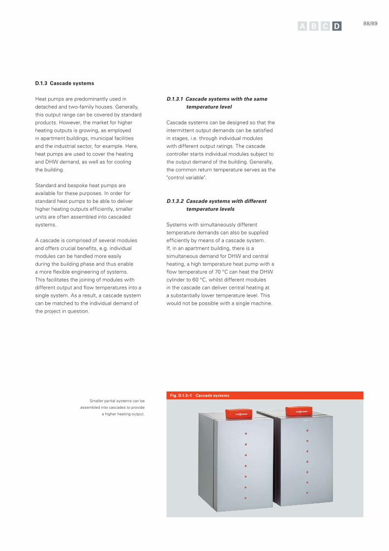
88/89
D.1.3 Cascade systems
Heat pumps are predominantly used in
detached and two-family houses. Generally,
this output range can be covered by standard
products. However, the market for higher
heating outputs is growing, as employed
in apartment buildings, municipal facilities
and the industrial sector, for example. Here,
heat pumps are used to cover the heating
and DHW demand, as well as for cooling
the building.
Standard and bespoke heat pumps are
available for these purposes. In order for
standard heat pumps to be able to deliver
higher heating outputs efficiently, smaller
units are often assembled into cascaded
systems.
A cascade is comprised of several modules
and offers crucial benefits, e.g. individual
modules can be handled more easily
during the building phase and thus enable
a more flexible engineering of systems.
This facilitates the joining of modules with
different output and flow temperatures into a
single system. As a result, a cascade system
can be matched to the individual demand of
the project in question.
D.1.3.1 Cascade systems with the same temperature level
Cascade systems can be designed so that the
intermittent output demands can be satisfied
in stages, i.e. through individual modules
with different output ratings. The cascade
controller starts individual modules subject to
the output demand of the building. Generally,
the common return temperature serves as the
"control variable".
D.1.3.2 Cascade systems with different temperature levels
Systems with simultaneously different
temperature demands can also be supplied
efficiently by means of a cascade system.
If, in an apartment building, there is a
simultaneous demand for DHW and central
heating, a high temperature heat pump with a
flow temperature of 70 °C can heat the DHW
cylinder to 60 °C, whilst different modules
in the cascade can deliver central heating at
a substantially lower temperature level. This
would not be possible with a single machine.
Smaller partial systems can be
assembled into cascades to provide
a higher heating output.
Fig. D.1.3–1 Cascade systems
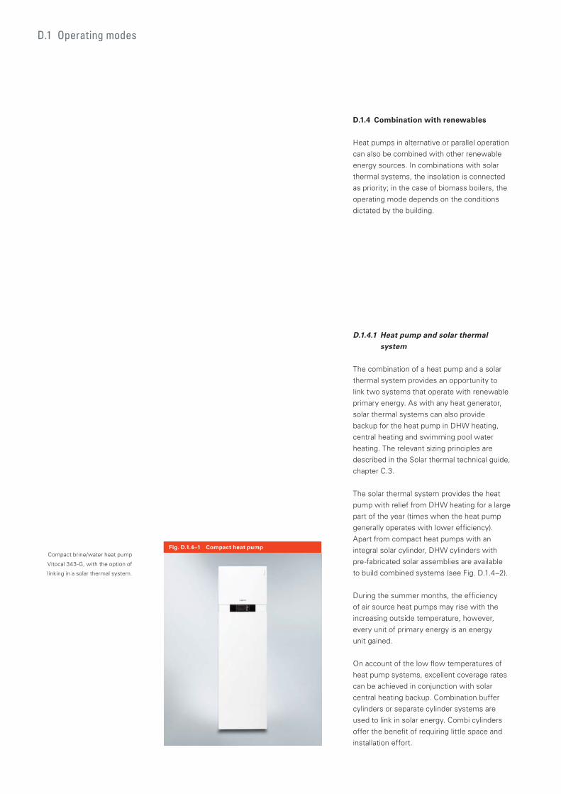
D.1 Operating modes
Fig. D.1.4–1 Compact heat pump
D.1.4 Combination with renewables
Heat pumps in alternative or parallel operation
can also be combined with other renewable
energy sources. In combinations with solar
thermal systems, the insolation is connected
as priority; in the case of biomass boilers, the
operating mode depends on the conditions
dictated by the building.
D.1.4.1 Heat pump and solar thermal system
The combination of a heat pump and a solar
thermal system provides an opportunity to
link two systems that operate with renewable
primary energy. As with any heat generator,
solar thermal systems can also provide
backup for the heat pump in DHW heating,
central heating and swimming pool water
heating. The relevant sizing principles are
described in the Solar thermal technical guide,
chapter C.3.
The solar thermal system provides the heat
pump with relief from DHW heating for a large
part of the year (times when the heat pump
generally operates with lower efficiency).
Apart from compact heat pumps with an
integral solar cylinder, DHW cylinders with
pre-fabricated solar assemblies are available
to build combined systems (see Fig. D.1.4–2).
During the summer months, the efficiency
of air source heat pumps may rise with the
increasing outside temperature, however,
every unit of primary energy is an energy
unit gained.
On account of the low flow temperatures of
heat pump systems, excellent coverage rates
can be achieved in conjunction with solar
central heating backup. Combination buffer
cylinders or separate cylinder systems are
used to link in solar energy. Combi cylinders
offer the benefit of requiring little space and
installation effort.
Compact brine/water heat pump
Vitocal 343-G, with the option of
linking in a solar thermal system.
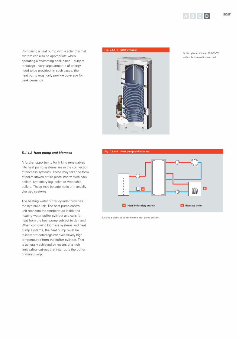
90/91
Fig. D.1.4–2 DHW cylinderCombining a heat pump with a solar thermal
system can also be appropriate when
operating a swimming pool, since – subject
to design – very large amounts of energy
need to be provided. In such cases, the
heat pump must only provide coverage for
peak demands.
D.1.4.2 Heat pump and biomass
A further opportunity for linking renewables
into heat pump systems lies in the connection
of biomass systems. These may take the form
of pellet stoves or fire place inserts with back
boilers, stationary log, pellet or woodchip
boilers. These may be automatic or manually
charged systems.
The heating water buffer cylinder provides
the hydraulic link. The heat pump control
unit monitors the temperature inside the
heating water buffer cylinder and calls for
heat from the heat pump subject to demand.
When combining biomass systems and heat
pump systems, the heat pump must be
reliably protected against excessively high
temperatures from the buffer cylinder. This
is generally achieved by means of a high
limit safety cut-out that interrupts the buffer
primary pump.
Fig. D.1.4–3 Heat pump and biomass
A
A
High limit safety cut-out Biomass boilerB
B
Linking a biomass boiler into the heat pump system.
DHW cylinder Vitocell 100-CVW,
with solar internal indirect coil.
D.2 Secondary circuit
The maximum flow temperature of the
heating system, the spread between system
temperatures, the DHW demand, as well
as the hydraulic design of the secondary
circuit system, all have a decisive impact
on energy consumption and running costs.
Although this applies generally to all systems
employing advanced heat generators,
the loss of efficiency with heat pumps
can be significantly higher as a result of
poorly engineered or implemented heating
circuits than, for example, with condensing
boilers. Careful system engineering is
therefore essential.
Heat pump systems should operate on the
secondary side with a spread of between
5 and 10 K. This enables the condenser to
operate with an efficient average condensing
temperature (condensation).
In the following, the heating operation and
DHW heating are described separately.
Secondary circuit
Apart from a sufficiently sized heat source and the selection of a suitable operating mode, the sizing and implementation of the secondary circuit are crucial factors for the efficiency of the heat pump.
92/93
D.2.1 DHW heating
DHW heating using heat pumps can be
covered – subject to requirements – with the
following systems:
Centralised DHW heating by means of a
DHW heat pump
Centralised DHW heating by means of
storage in a DHW cylinder
Centralised DHW heating by means of
storing the heating water in a buffer
cylinder and centralised freshwater module
Decentralised heating via individual
apartment stations
Decentralised heating via electrical
instantaneous water heater
D.2.1.1 Temperature and hygiene considerations
When designing DHW heating systems, two
principle requirements must be met, that if
considered separately would result in different
sizing and system components. For reasons
of hygiene, the amount of stored DHW should
be kept to a minimum; in other words DHW
cylinders with a small volume should be
selected. The smaller the cylinder volume, the
greater the heat generator output to cover the
heat demand. Given a good modulation level,
this is easily accomplished with conventional
heat generators and it is comparatively
affordable.
When the heat generator only delivers a
limited output, a larger cylinder capacity will
be required in order to be able to cover the
DHW demand. In other words, planning DHW
heating when using heat pump systems
requires great care.
The DVGW Code of Practice W 551
differentiates between small and large
systems where hygiene is concerned. Small
systems are DHW systems in detached and
two-family houses – independent of the
volume of the DHW cylinder and the content
of the pipework. Systems with a cylinder
capacity below 400 l and a pipework content
no larger than 3 l between the DHW cylinder
connection and the draw-off point, are also
considered to be small systems.
Systems in apartment buildings and public
installations are considered to be large if
their cylinder capacity exceeds 400 l and/or
the water content in each pipeline between
the DHW cylinder and the draw-off point is
greater than 3 l.
For large systems, the DVGW Code of
Practice W 551 requires a permanent DHW
outlet temperature of at least 60 °C at the
DHW cylinder. The return temperature of the
DHW circulation pipe must be at least 55 °C.
The DHW content of preheat stages must be
heated to 60 °C, or higher, at least once every
day. For small systems, an outlet temperature
of 60 °C must be maintained.
On account of the refrigerants used,
conventional heat pumps can generally
achieve maximum flow temperatures of
between 55 °C and 65 °C. With a flow
temperature of 55 °C, DHW temperatures
of 48 °C can be achieved; with a flow
temperature of 65 °C, maximum DHW
temperatures of 58 °C can be reached. In
order to achieve these temperatures in the
DHW cylinder, heat pumps operate with a
very low coefficient of performance
(COP 2.5 – 3.3, depending on the heat
source temperature).
Cylinders need to be reheated to an outlet
temperature of 60 °C in order to meet the
hygienic requirements of DHW cylinders in
apartment buildings. This may be brought
about by a dual mode heat generator, by heat
pumps with flow temperatures of up to 75 °C
developed specifically for this purpose, or by
direct electric heaters.
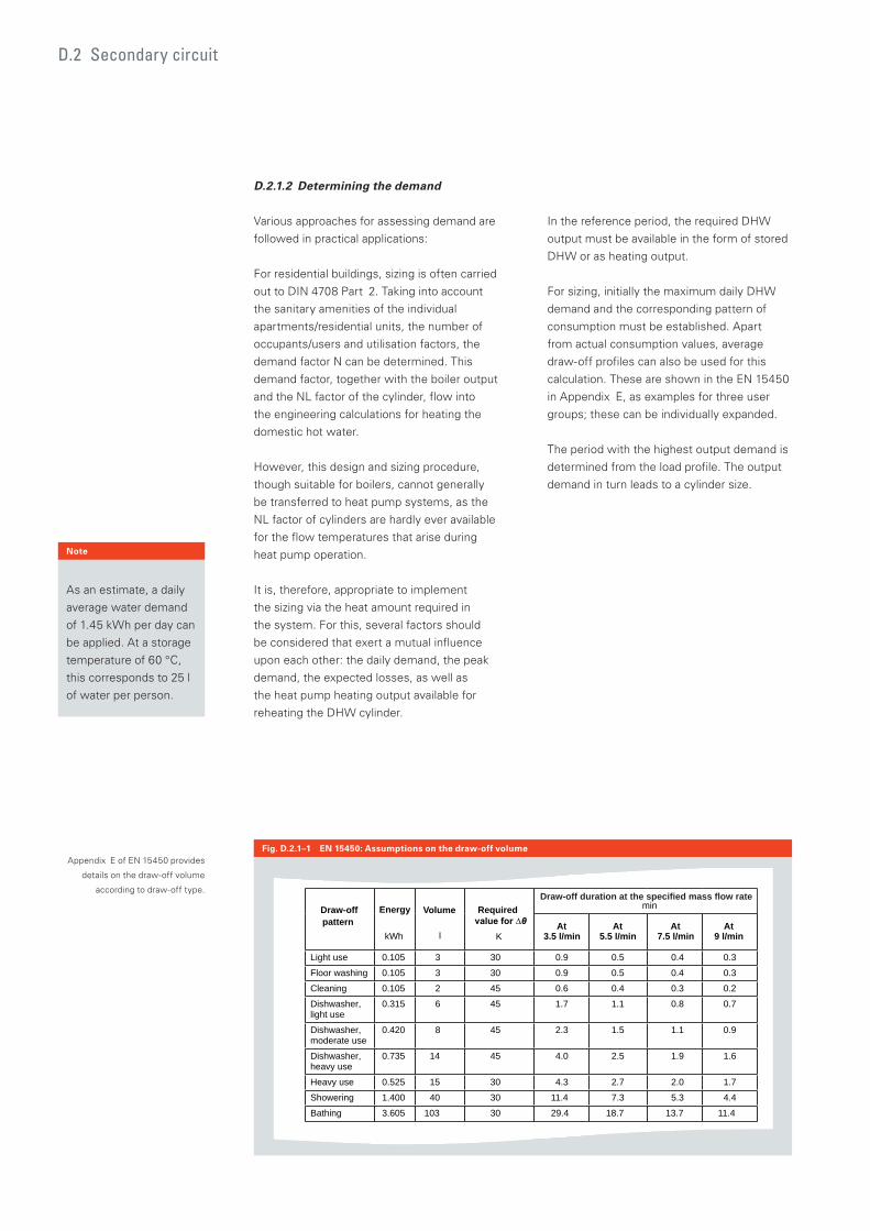
D.2.1.2 Determining the demand
Various approaches for assessing demand are
followed in practical applications:
For residential buildings, sizing is often carried
out to DIN 4708 Part 2. Taking into account
the sanitary amenities of the individual
apartments/residential units, the number of
occupants/users and utilisation factors, the
demand factor N can be determined. This
demand factor, together with the boiler output
and the NL factor of the cylinder, flow into
the engineering calculations for heating the
domestic hot water.
However, this design and sizing procedure,
though suitable for boilers, cannot generally
be transferred to heat pump systems, as the
NL factor of cylinders are hardly ever available
for the flow temperatures that arise during
heat pump operation.
It is, therefore, appropriate to implement
the sizing via the heat amount required in
the system. For this, several factors should
be considered that exert a mutual influence
upon each other: the daily demand, the peak
demand, the expected losses, as well as
the heat pump heating output available for
reheating the DHW cylinder.
In the reference period, the required DHW
output must be available in the form of stored
DHW or as heating output.
For sizing, initially the maximum daily DHW
demand and the corresponding pattern of
consumption must be established. Apart
from actual consumption values, average
draw-off profiles can also be used for this
calculation. These are shown in the EN 15450
in Appendix E, as examples for three user
groups; these can be individually expanded.
The period with the highest output demand is
determined from the load profile. The output
demand in turn leads to a cylinder size.
D.2 Secondary circuit
Fig. D.2.1–1 EN 15450: Assumptions on the draw-off volumeAppendix E of EN 15450 provides
details on the draw-off volume
according to draw-off type.
Note
As an estimate, a daily
average water demand
of 1.45 kWh per day can
be applied. At a storage
temperature of 60 °C,
this corresponds to 25 l
of water per person.
Draw-off pattern
Energy
kWh
Volume
l
Required
K
min
At 3.5 l/min
At 5.5 l/min
At 7.5 l/min
At 9 l/min
Light use 0.105 3 30 0.9 0.5 0.4 0.3
Floor washing 0.105 3 30 0.9 0.5 0.4 0.3
Cleaning 0.105 2 45 0.6 0.4 0.3 0.2
Dishwasher, light use
0.315 6 45 1.7 1.1 0.8 0.7
Dishwasher, moderate use
0.420 8 45 2.3 1.5 1.1 0.9
Dishwasher, heavy use
0.735 14 45 4.0 2.5 1.9 1.6
Heavy use 0.525 15 30 4.3 2.7 2.0 1.7
Showering 1.400 40 30 11.4 7.3 5.3 4.4
Bathing 3.605 103 30 29.4 18.7 13.7 11.4
Draw-off duration at the specified mass flow rate
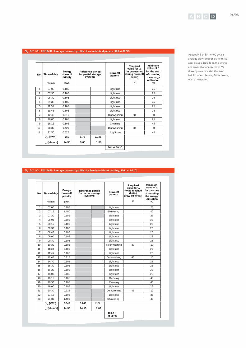
94/95
Fig. D.2.1–2 EN 15450: Average draw-off profile of an individual person (36 l at 60 °C)
Fig. D.2.1–3 EN 15450: Average draw-off profile of a family (without bathing, 100 l at 60 °C)
Appendix E of EN 15450 details
average draw-off profiles for three
user groups. Details on the timing
and amount of energy for DHW
drawings are provided that are
helpful when planning DHW heating
with a heat pump.
43
No. Time of day
hh:mm
Energy draw-off priority
kWh
Reference period for partial storage
systems Draw-off pattern
Requiredvalue for
(to be reached during
draw-off event)
K
Minimum value of
for the start of counting the energy utilisation
°C
1 07:00 0.105 Light use 25
2 07:15 1.400 Showering 40
3 07:30 0.105 Light use 25
4 08:01 0.105 Light use 25
5 08:15 0.105 Light use 25
6 08:30 0.105 Light use 25
7 08:45 0.105 Light use 25
8 09:00 0.105 Light use 25
9 09:30 0.105 Light use 25
10 10:30 0.105 Floor washing 30 10
11 11:30 0.105 Light use 25
12 11:45 0.105 Light use 25
13 12:45 0.315 Dishwashing 45 10
14 14:30 0.105 Light use 25
15 15:30 0.105 Light use 25
16 16:30 0.105 Light use 25
17 18:00 0.105 Light use 25
18 18:15 0.105 Cleaning 40
19 18:30 0.105 Cleaning 40
20 19:00 0.105 Light use 25
21 20:30 0.735 Dishwashing 45 10
22 21:15 0.105 Light use 25
23 21:30 1.400 Showering 40
QDP [kWh]
tDP [hh:mm]
5.845
14:30
5.740
14:15
2.24
1:00
100.2 l at 60 °C
No. Time of day
hh:mm
Energy draw-off priority
kWh
Reference period for partial storage
systems Draw-off pattern
Required value for
(to be reached during draw-off
event)
K
Minimum value of
for the start of counting the energy utilisation
°C
1 07:00 0.105 Light use 25
2 07:30 0.105 Light use 25
3 08:30 0.105 Light use 25
4 09:30 0.105 Light use 25
5 11:30 0.105 Light use 25
6 11:45 0.105 Light use 25
7 12:45 0.315 Dishwashing 50 0
8 18:00 0.105 Light use 25
9 18:15 0.105 Cleaning 45
10 20:30 0.420 Dishwashing 50 0
11 21:30 0.525 Light use 45
QDP [kWh]
tDP [hh:mm]
2.1
14:30
1.78
9:00
0.945
1:00
36 l at 60 °C
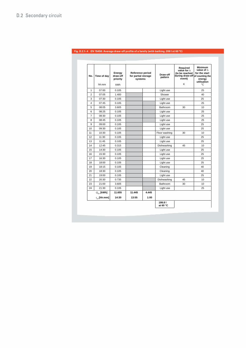
D.2 Secondary circuit
Fig. D.2.1–4 EN 15450: Average draw-off profile of a family (with bathing, 200 l at 60 °C)
44
No. Time of day
hh:mm
Energy draw-off priority
kWh
Reference periodfor partial storage
systems Draw-off pattern
Required value for
(to be reached during draw-off
event)
K
Minimum value of
for the start of counting the
energy utilisation
°C
1 07:00 0.105 Light use 25
2 07:05 1.400 Shower 40
3 07:30 0.105 Light use 25
4 07:45 0.105 Light use 25
5 08:05 3.605 Bathroom 30 10
6 08:25 0.105 Light use 25
7 08:30 0.105 Light use 25
8 08:45 0.105 Light use 25
9 09:00 0.105 Light use 25
10 09:30 0.105 Light use 25
11 10:30 0.105 Floor washing 30 10
12 11:30 0.105 Light use 25
13 11:45 0.105 Light use 25
14 12:45 0.315 Dishwashing 45 10
15 14:30 0.105 Light use 25
16 15:30 0.105 Light use 25
17 16:30 0.105 Light use 25
18 18:00 0.105 Light use 25
19 18:15 0.105 Cleaning 40
20 18:30 0.105 Cleaning 40
21 19:00 0.105 Light use 25
22 20:30 0.735 Dishwashing 45 10
23 21:00 3.605 Bathroom 30 10
24 21:30 0.105 Light use 25
QDP [kWh]
tDP [hh:mm]
11.655
14:30
11.445
13:55
4.445
1:00
199.8 l at 60 °C
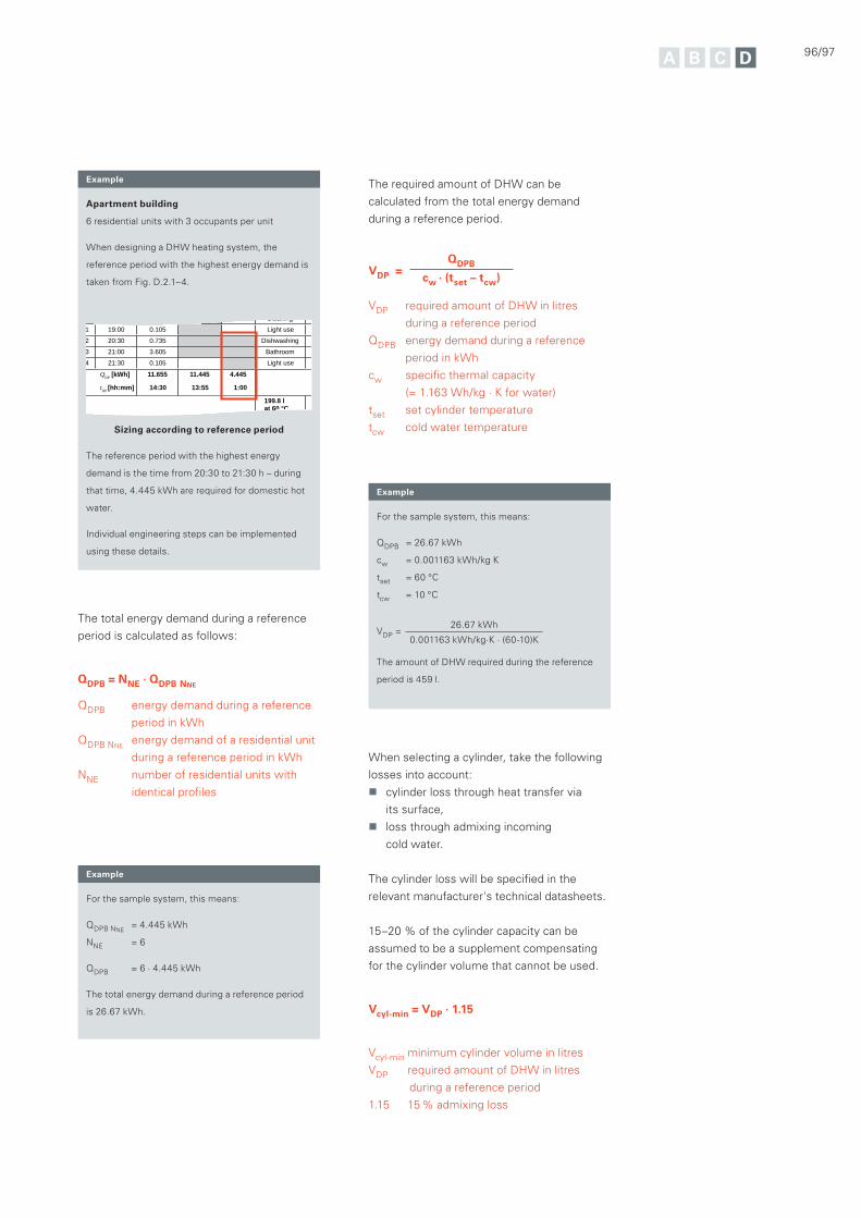
Apartment building
6 residential units with 3 occupants per unit
When designing a DHW heating system, the
reference period with the highest energy demand is
taken from Fig. D.2.1–4.
Sizing according to reference period
The reference period with the highest energy
demand is the time from 20:30 to 21:30 h – during
that time, 4.445 kWh are required for domestic hot
water.
Individual engineering steps can be implemented
using these details.
4
0 18:30 0.105 Cleaning
1 19:00 0.105 Light use
2 20:30 0.735 Dishwashing
3 21:00 3.605 Bathroom
4 21:30 0.105 Light use
QDP [kWh]
tDP [hh:mm]
11.655
14:30
11.445
13:55
4.445
1:00
199.8 l at 60 °C
96/97
Example
Example
Example
The total energy demand during a reference
period is calculated as follows:
QDPB = NNE · QDPB NNE
QDPB energy demand during a reference
period in kWh
QDPB NNE energy demand of a residential unit
during a reference period in kWh
NNE number of residential units with
identical profiles
When selecting a cylinder, take the following
losses into account:
cylinder loss through heat transfer via
its surface,
loss through admixing incoming
cold water.
The cylinder loss will be specified in the
relevant manufacturer's technical datasheets.
15–20 % of the cylinder capacity can be
assumed to be a supplement compensating
for the cylinder volume that cannot be used.
Vcyl-min = VDP · 1.15
Vcyl-min minimum cylinder volume in litres
VDP required amount of DHW in litres
during a reference period
1.15 15 % admixing loss
For the sample system, this means:
QDPB NNE = 4.445 kWh
NNE = 6
QDPB = 6 · 4.445 kWh
The total energy demand during a reference period
is 26.67 kWh.
For the sample system, this means:
QDPB = 26.67 kWh
cw = 0.001163 kWh/kg K
tset = 60 °C
tcw = 10 °C
VDP = 26.67 kWh
0.001163 kWh/kg·K · (60-10)K
The amount of DHW required during the reference
period is 459 l.
The required amount of DHW can be
calculated from the total energy demand
during a reference period.
VDP = QDPB
cw · (tset – tcw)
VDP required amount of DHW in litres
during a reference period
QDPB energy demand during a reference
period in kWh
cw specific thermal capacity
(= 1.163 Wh/kg · K for water)
tset set cylinder temperature
tcw cold water temperature
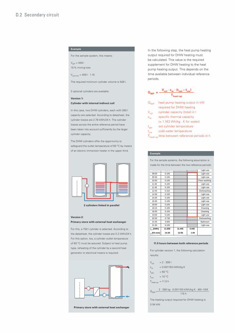
For the sample systems, the following assumption is
made for the time between the two reference periods:
11.5 hours between both reference periods
For cylinder version 1, the following calculation
results:
Vcyl = 2 · 390 l
cw = 0.001163 kWh/kg K
tset = 60 °C
tcw = 10 °C
Theat-up = 11.5 h
QWP = 2 · 390 kg · 0.001163 kWh/kg·K · (60–10)K
115 h
The heating output required for DHW heating is
3.94 kW.
08:45 0.105 Light use
09:00 0.105 Light use
09:30 0.105 Light use
10:30 0.105 Floor washing
11:30 0.105 Light use
11:45 0.105 Light use
12:45 0.315 Dishwashing
14:30 0.105 Light use
15:30 0.105 Light use
16:30 0.105 Light use
18:00 0.105 Light use
18:15 0.105 Cleaning
18:30 0.105 Cleaning
19:00 0.105 Light use
20:30 0.735 Dishwashing
21:00 3.605 Bathroom
21:30 0.105 Light use
QDP [kWh]
tDP [hh:mm]
11.655
14:30
11.445
13:55
4.445
1:00
199 8 l
For the sample system, this means:
VDP = 459 l
15 % mixing loss
Vcyl-min = 459 l · 1.15
The required minimum cylinder volume is 528 l.
2 optional cylinders are available:
Version 1:
Cylinder with internal indirect coil
In this case, two DHW cylinders, each with 390 l
capacity are selected. According to datasheet, the
cylinder losses are 2.78 kWh/24 h. The cylinder
losses across the entire reference period have
been taken into account sufficiently by the larger
cylinder capacity.
The DHW cylinders offer the opportunity to
safeguard the outlet temperature of 60 °C by means
of an electric immersion heater in the upper third.
2 cylinders linked in parallel
Version 2:
Primary store with external heat exchanger
For this, a 750 l cylinder is selected. According to
the datasheet, the cylinder losses are 3.2 kWh/24 h.
For this option, too, a cylinder outlet temperature
of 60 °C must be assured. Subject to heat pump
type, reheating of the cylinder by a second heat
generator or electrical means is required.
Primary store with external heat exchanger
Example
Example In the following step, the heat pump heating
output required for DHW heating must
be calculated. This value is the required
supplement for DHW heating to the heat
pump heating output. This depends on the
time available between individual reference
periods.
QWP = Vcyl · cw · (tset – tcw)
Theat-up
QWP heat pump heating output in kW
required for DHW heating
Vcyl cylinder capacity (total) in l
cw specific thermal capacity
(= 1.163 Wh/kg · K for water)
tset set cylinder temperature
tcw cold water temperature
Theat-up time between reference periods in h
D.2 Secondary circuit
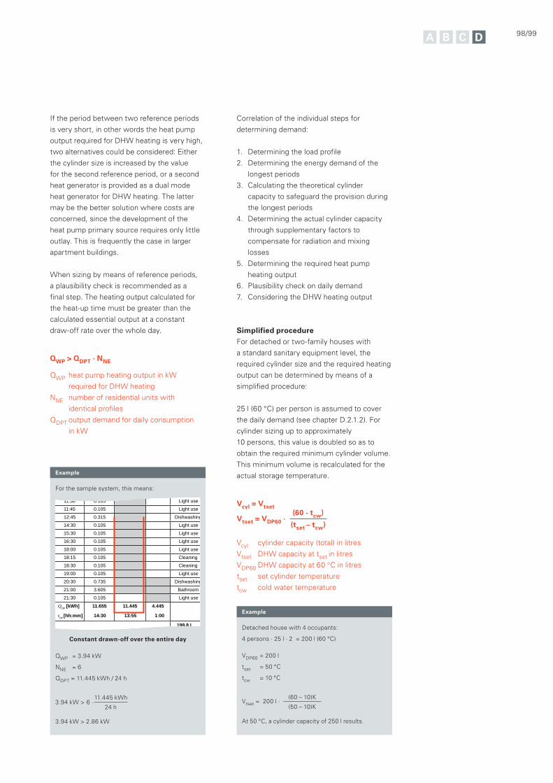
98/99
If the period between two reference periods
is very short, in other words the heat pump
output required for DHW heating is very high,
two alternatives could be considered: Either
the cylinder size is increased by the value
for the second reference period, or a second
heat generator is provided as a dual mode
heat generator for DHW heating. The latter
may be the better solution where costs are
concerned, since the development of the
heat pump primary source requires only little
outlay. This is frequently the case in larger
apartment buildings.
When sizing by means of reference periods,
a plausibility check is recommended as a
final step. The heating output calculated for
the heat-up time must be greater than the
calculated essential output at a constant
draw-off rate over the whole day.
QWP > QDPT · NNE
QWP heat pump heating output in kW
required for DHW heating
NNE number of residential units with
identical profiles
QDPT output demand for daily consumption
in kW
For the sample system, this means:
Constant drawn-off over the entire day
QWP = 3.94 kW
NNE = 6
QDPT = 11.445 kWh / 24 h
3.94 kW > 6 ·11.445 kWh
24 h
3.94 kW > 2.86 kW
Detached house with 4 occupants:
4 persons · 25 l · 2 = 200 l (60 °C)
VDP60 = 200 l
tset = 50 °C
tcw = 10 °C
Vtset = 200 l ·(60 – 10)K
(50 – 10)K
At 50 °C, a cylinder capacity of 250 l results.
Example
Example
Correlation of the individual steps for
determining demand:
1. Determining the load profile
2. Determining the energy demand of the
longest periods
3. Calculating the theoretical cylinder
capacity to safeguard the provision during
the longest periods
4. Determining the actual cylinder capacity
through supplementary factors to
compensate for radiation and mixing
losses
5. Determining the required heat pump
heating output
6. Plausibility check on daily demand
7. Considering the DHW heating output
Simplified procedure
For detached or two-family houses with
a standard sanitary equipment level, the
required cylinder size and the required heating
output can be determined by means of a
simplified procedure:
25 l (60 °C) per person is assumed to cover
the daily demand (see chapter D.2.1.2). For
cylinder sizing up to approximately
10 persons, this value is doubled so as to
obtain the required minimum cylinder volume.
This minimum volume is recalculated for the
actual storage temperature.
Vcyl = Vtset
Vtset = VDP60 ·(60 - tcw)
(tset – tcw)
Vcyl cylinder capacity (total) in litres
Vtset DHW capacity at tset in litres
VDP60 DHW capacity at 60 °C in litres
tset set cylinder temperature
tcw cold water temperature
11:30 0.105 Light use
11:45 0.105 Light use
12:45 0.315 Dishwashing
14:30 0.105 Light use
15:30 0.105 Light use
16:30 0.105 Light use
18:00 0.105 Light use
18:15 0.105 Cleaning
18:30 0.105 Cleaning
19:00 0.105 Light use
20:30 0.735 Dishwashing
21:00 3.605 Bathroom
21:30 0.105 Light use
QDP [kWh]
tDP [hh:mm]
11.655
14:30
11.445
13:55
4.445
1:00
199.8 l at 60 °C
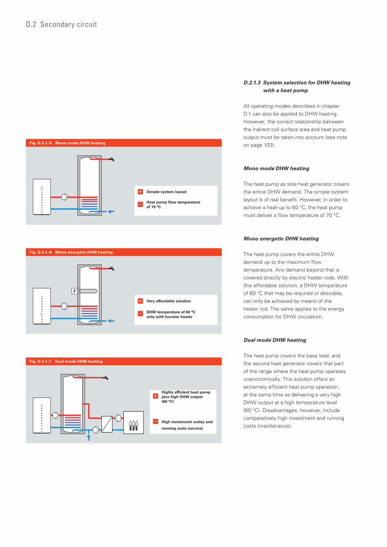
D.2.1.3 System selection for DHW heating with a heat pump
All operating modes described in chapter
D.1 can also be applied to DHW heating.
However, the correct relationship between
the indirect coil surface area and heat pump
output must be taken into account (see note
on page 103).
Mono mode DHW heating
The heat pump as sole heat generator covers
the entire DHW demand. The simple system
layout is of real benefit. However, in order to
achieve a heat-up to 60 °C, the heat pump
must deliver a flow temperature of 70 °C.
Mono energetic DHW heating
The heat pump covers the entire DHW
demand up to the maximum flow
temperature. Any demand beyond that is
covered directly by electric heater rods. With
this affordable solution, a DHW temperature
of 60 °C that may be required or desirable,
can only be achieved by means of the
heater rod. The same applies to the energy
consumption for DHW circulation.
Dual mode DHW heating
The heat pump covers the base load, and
the second heat generator covers that part
of the range where the heat pump operates
uneconomically. This solution offers an
extremely efficient heat pump operation,
at the same time as delivering a very high
DHW output at a high temperature level
(60 °C). Disadvantages, however, include
comparatively high investment and running
costs (maintenance).
D.2 Secondary circuit
Highly efficient heat pumpplus high DHW output (60 °C)
High investment outlay and
running costs (service)
Simple system layout
Heat pump flow temperatureof 70 °C
Very affordable solution
DHW temperature of 60 °C only with booster heater
Fig. D.2.1–5 Mono mode DHW heating
Fig. D.2.1–7 Dual mode DHW heating
Fig. D.2.1–6 Mono energetic DHW heating
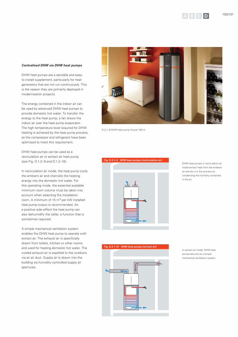
100/101
Centralised DHW via DHW heat pumps
DHW heat pumps are a sensible and easy-
to-install supplement, particularly for heat
generators that are not run continuously. This
is the reason they are primarily deployed in
modernisation projects.
The energy contained in the indoor air can
be used by advanced DHW heat pumps to
provide domestic hot water. To transfer the
energy to the heat pump, a fan draws the
indoor air over the heat pump evaporator.
The high temperature level required for DHW
heating is achieved by the heat pump process,
as the compressor and refrigerant have been
optimised to meet this requirement.
DHW heat pumps can be used as a
recirculation air or extract air heat pump
(see Fig. D.1.2–9 and D.1.2–10).
In recirculation air mode, the heat pump cools
the ambient air and channels the heating
energy into the domestic hot water. For
this operating mode, the essential available
minimum room volume must be taken into
account when selecting the installation
room. A minimum of 15 m3 per kW installed
heat pump output is recommended. As
a positive side-effect the heat pump can
also dehumidify the cellar, a function that is
sometimes required.
A simple mechanical ventilation system
enables the DHW heat pump to operate with
extract air. The exhaust air is specifically
drawn from toilets, kitchen or other rooms
and used for heating domestic hot water. The
cooled exhaust air is expelled to the outdoors
via an air duct. Supply air is drawn into the
building via humidity-controlled supply air
apertures.
Fig. D.2.1–10 DHW heat pumps (extract air)
Fig. D.2.1–9 DHW heat pumps (recirculation air)
D.2.1–8 DHW heat pump Vitocal 160-A.
DHW heat pumps in recirculation air
mode extract heat from the ambient
air and dry it in the process by
condensing the humidity contained
in the air.
In extract air mode, DHW heat
pumps also act as a simple
mechanical ventilation system.
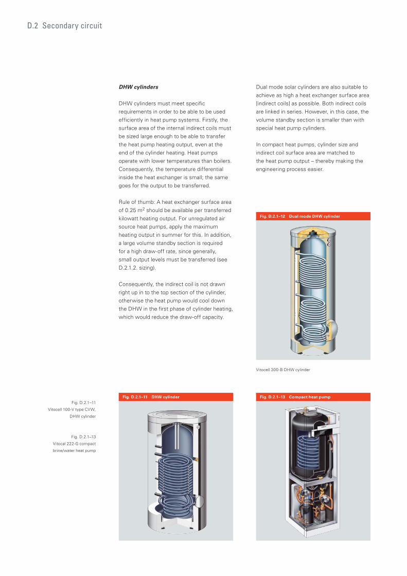
DHW cylinders
DHW cylinders must meet specific
requirements in order to be able to be used
efficiently in heat pump systems. Firstly, the
surface area of the internal indirect coils must
be sized large enough to be able to transfer
the heat pump heating output, even at the
end of the cylinder heating. Heat pumps
operate with lower temperatures than boilers.
Consequently, the temperature differential
inside the heat exchanger is small; the same
goes for the output to be transferred.
Rule of thumb: A heat exchanger surface area
of 0.25 m2 should be available per transferred
kilowatt heating output. For unregulated air
source heat pumps, apply the maximum
heating output in summer for this. In addition,
a large volume standby section is required
for a high draw-off rate, since generally,
small output levels must be transferred (see
D.2.1.2. sizing).
Consequently, the indirect coil is not drawn
right up in to the top section of the cylinder,
otherwise the heat pump would cool down
the DHW in the first phase of cylinder heating,
which would reduce the draw-off capacity.
Dual mode solar cylinders are also suitable to
achieve as high a heat exchanger surface area
[indirect coils] as possible. Both indirect coils
are linked in series. However, in this case, the
volume standby section is smaller than with
special heat pump cylinders.
In compact heat pumps, cylinder size and
indirect coil surface area are matched to
the heat pump output – thereby making the
engineering process easier.
D.2 Secondary circuit
Fig. D.2.1–12 Dual mode DHW cylinder
Fig. D.2.1–11 DHW cylinder Fig. D.2.1–13 Compact heat pump
Vitocell 300-B DHW cylinder
Fig. D.2.1–11
Vitocell 100-V type CVW,
DHW cylinder
Fig. D.2.1–13
Vitocal 222-G compact
brine/water heat pump
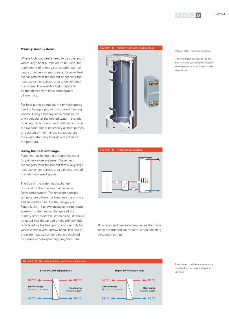
102/103
Fig. D.2.1–15 Heating lance function
Fig. D.2.1–16 Designing indirect coils/heat exchangers
40 °C
60 °C50 °C
50 °C
Heat pump(heating water)
DHW cylinder (domestic hot water)
53 °C
60 °C58 °C
55 °C
Heat pump(heating water)
DHW cylinder (domestic hot water)
Standard DHW temperatures Higher DHW temperatures
Primary store systems
Where high load peaks need to be covered, or
where large heat pumps are to be used, the
deployment of primary stores with external
heat exchangers is appropriate. External heat
exchangers offer the benefit of enabling the
heat exchanger surface area to be selected
in any size. This enables high outputs to
be transferred with small temperature
differentials.
For heat pump operation, the primary stores
need to be equipped with so-called "heating
lances". Using a heating lance reduces the
entry velocity of the heated water – thereby
retaining the temperature stratification inside
the cylinder. This is necessary as heat pumps,
on account of their narrow spread across
the evaporator, only tolerate a slight rise in
temperature.
Sizing the heat exchanger
Plate heat exchangers are frequently used
for primary store systems. These heat
exchangers offer the benefit that a very large
heat exchanger surface area can be provided
in a relatively small space.
The size of the plate heat exchanger
is crucial for the maximum achievable
DHW temperature. The smallest possible
temperature differential between the primary
and secondary circuit is the design goal.
Figure D.2.1–16 shows possible temperature
spreads for the heat exchangers of the
primary store systems. When sizing, it should
be noted that the spread on the primary side
is dictated by the heat pump and can only be
varied within a very narrow band. The size of
the plate heat exchanger can be calculated
by means of corresponding programs. The
Fig. D.2.1–14 Primary store with heating lance Vitocell 100-L, with heating lance
The heating lance reduces the inlet
flow rate and consequently protects
the temperature stratification inside
the cylinder.
flow rates and pressure drop values that have
been determined are required when selecting
circulation pumps.
Freshwater modules are particularly
suitable for covering a high output
demand.
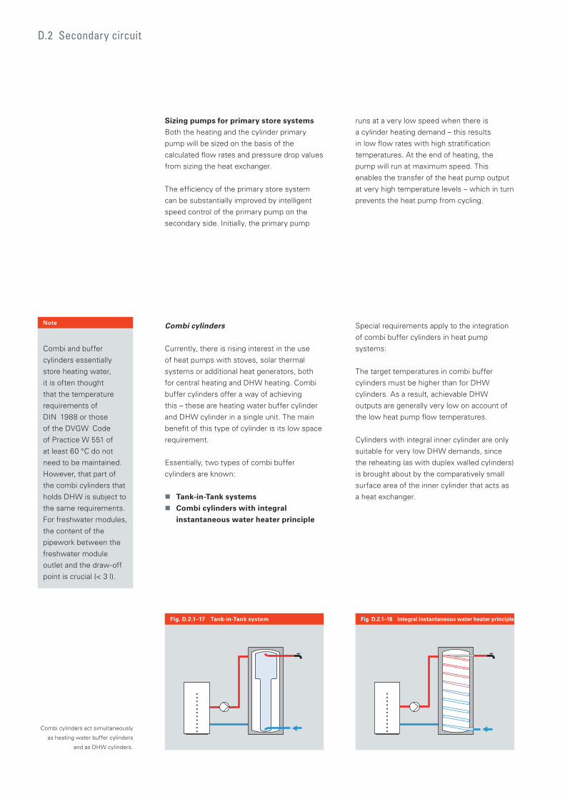
Combi cylinders
Currently, there is rising interest in the use
of heat pumps with stoves, solar thermal
systems or additional heat generators, both
for central heating and DHW heating. Combi
buffer cylinders offer a way of achieving
this – these are heating water buffer cylinder
and DHW cylinder in a single unit. The main
benefit of this type of cylinder is its low space
requirement.
Essentially, two types of combi buffer
cylinders are known:
Tank-in-Tank systems
Combi cylinders with integral
instantaneous water heater principle
Fig. D.2.1–17 Tank-in-Tank system Fig. D.2.1–18 Integral instantaneous water heater principle
Special requirements apply to the integration
of combi buffer cylinders in heat pump
systems:
The target temperatures in combi buffer
cylinders must be higher than for DHW
cylinders. As a result, achievable DHW
outputs are generally very low on account of
the low heat pump flow temperatures.
Cylinders with integral inner cylinder are only
suitable for very low DHW demands, since
the reheating (as with duplex walled cylinders)
is brought about by the comparatively small
surface area of the inner cylinder that acts as
a heat exchanger.
Note
Combi and buffer
cylinders essentially
store heating water,
it is often thought
that the temperature
requirements of
DIN 1988 or those
of the DVGW Code
of Practice W 551 of
at least 60 °C do not
need to be maintained.
However, that part of
the combi cylinders that
holds DHW is subject to
the same requirements.
For freshwater modules,
the content of the
pipework between the
freshwater module
outlet and the draw-off
point is crucial (< 3 l).
Combi cylinders act simultaneously
as heating water buffer cylinders
and as DHW cylinders.
D.2 Secondary circuit
Sizing pumps for primary store systems
Both the heating and the cylinder primary
pump will be sized on the basis of the
calculated flow rates and pressure drop values
from sizing the heat exchanger.
The efficiency of the primary store system
can be substantially improved by intelligent
speed control of the primary pump on the
secondary side. Initially, the primary pump
runs at a very low speed when there is
a cylinder heating demand – this results
in low flow rates with high stratification
temperatures. At the end of heating, the
pump will run at maximum speed. This
enables the transfer of the heat pump output
at very high temperature levels – which in turn
prevents the heat pump from cycling.
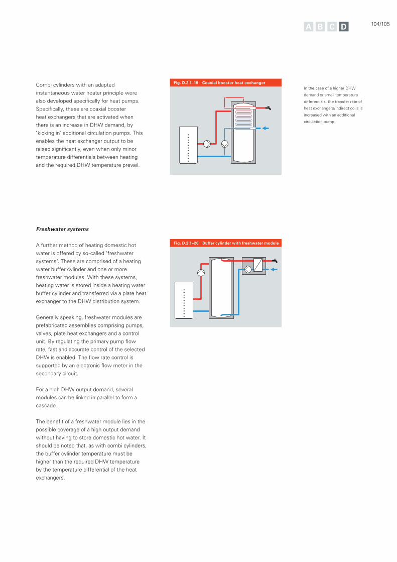
104/105
Fig. D.2.1–20 Buffer cylinder with freshwater module
Fig. D.2.1–19 Coaxial booster heat exchanger
Freshwater systems
A further method of heating domestic hot
water is offered by so-called "freshwater
systems". These are comprised of a heating
water buffer cylinder and one or more
freshwater modules. With these systems,
heating water is stored inside a heating water
buffer cylinder and transferred via a plate heat
exchanger to the DHW distribution system.
Generally speaking, freshwater modules are
prefabricated assemblies comprising pumps,
valves, plate heat exchangers and a control
unit. By regulating the primary pump flow
rate, fast and accurate control of the selected
DHW is enabled. The flow rate control is
supported by an electronic flow meter in the
secondary circuit.
For a high DHW output demand, several
modules can be linked in parallel to form a
cascade.
The benefit of a freshwater module lies in the
possible coverage of a high output demand
without having to store domestic hot water. It
should be noted that, as with combi cylinders,
the buffer cylinder temperature must be
higher than the required DHW temperature
by the temperature differential of the heat
exchangers.
Combi cylinders with an adapted
instantaneous water heater principle were
also developed specifically for heat pumps.
Specifically, these are coaxial booster
heat exchangers that are activated when
there is an increase in DHW demand, by
"kicking in" additional circulation pumps. This
enables the heat exchanger output to be
raised significantly, even when only minor
temperature differentials between heating
and the required DHW temperature prevail.
In the case of a higher DHW
demand or small temperature
differentials, the transfer rate of
heat exchangers/indirect coils is
increased with an additional
circulation pump.
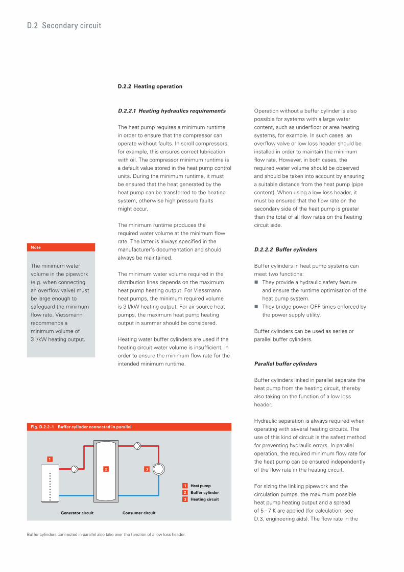
D.2 Secondary circuit
D.2.2 Heating operation
D.2.2.1 Heating hydraulics requirements
The heat pump requires a minimum runtime
in order to ensure that the compressor can
operate without faults. In scroll compressors,
for example, this ensures correct lubrication
with oil. The compressor minimum runtime is
a default value stored in the heat pump control
units. During the minimum runtime, it must
be ensured that the heat generated by the
heat pump can be transferred to the heating
system, otherwise high pressure faults
might occur.
The minimum runtime produces the
required water volume at the minimum flow
rate. The latter is always specified in the
manufacturer's documentation and should
always be maintained.
The minimum water volume required in the
distribution lines depends on the maximum
heat pump heating output. For Viessmann
heat pumps, the minimum required volume
is 3 l/kW heating output. For air source heat
pumps, the maximum heat pump heating
output in summer should be considered.
Heating water buffer cylinders are used if the
heating circuit water volume is insufficient, in
order to ensure the minimum flow rate for the
intended minimum runtime.
Operation without a buffer cylinder is also
possible for systems with a large water
content, such as underfloor or area heating
systems, for example. In such cases, an
overflow valve or low loss header should be
installed in order to maintain the minimum
flow rate. However, in both cases, the
required water volume should be observed
and should be taken into account by ensuring
a suitable distance from the heat pump (pipe
content). When using a low loss header, it
must be ensured that the flow rate on the
secondary side of the heat pump is greater
than the total of all flow rates on the heating
circuit side.
D.2.2.2 Buffer cylinders
Buffer cylinders in heat pump systems can
meet two functions:
They provide a hydraulic safety feature
and ensure the runtime optimisation of the
heat pump system.
They bridge power-OFF times enforced by
the power supply utility.
Buffer cylinders can be used as series or
parallel buffer cylinders.
Parallel buffer cylinders
Buffer cylinders linked in parallel separate the
heat pump from the heating circuit, thereby
also taking on the function of a low loss
header.
Hydraulic separation is always required when
operating with several heating circuits. The
use of this kind of circuit is the safest method
for preventing hydraulic errors. In parallel
operation, the required minimum flow rate for
the heat pump can be ensured independently
of the flow rate in the heating circuit.
For sizing the linking pipework and the
circulation pumps, the maximum possible
heat pump heating output and a spread
of 5 – 7 K are applied (for calculation, see
D.3, engineering aids). The flow rate in the
Fig. D.2.2–1 Buffer cylinder connected in parallel
2
1 Heat pump
Buffer cylinder
Heating circuit3
2
1
3
Generator circuit Consumer circuit
The minimum water
volume in the pipework
(e.g. when connecting
an overflow valve) must
be large enough to
safeguard the minimum
flow rate. Viessmann
recommends a
minimum volume of
3 l/kW heating output.
Note
Buffer cylinders connected in parallel also take over the function of a low loss header.
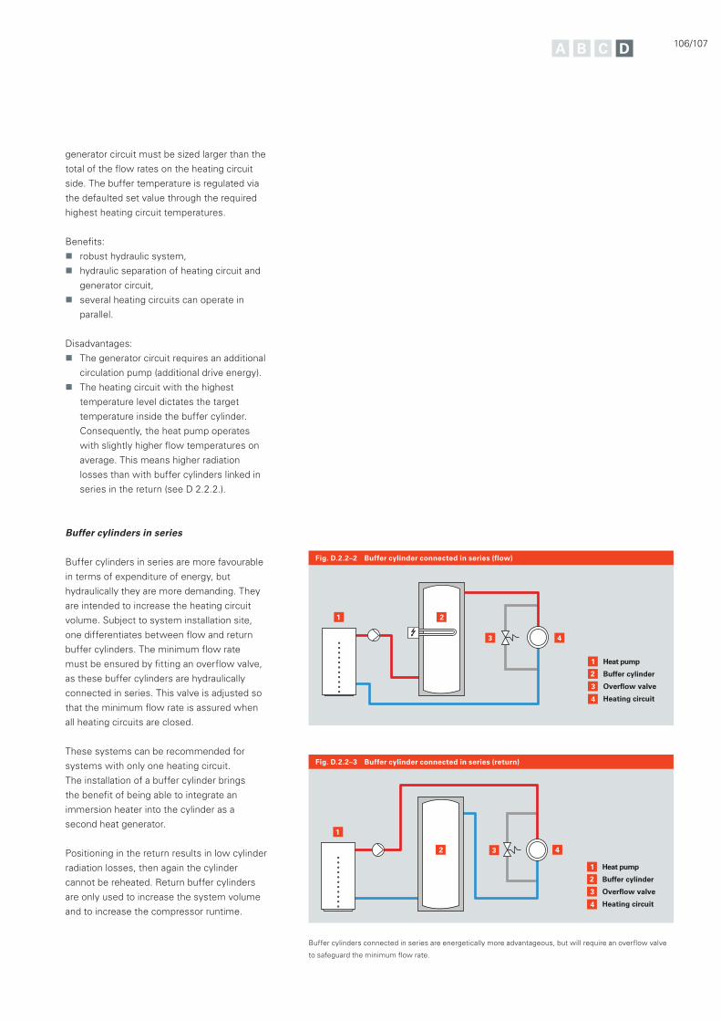
106/107
generator circuit must be sized larger than the
total of the flow rates on the heating circuit
side. The buffer temperature is regulated via
the defaulted set value through the required
highest heating circuit temperatures.
Benefits:
robust hydraulic system,
hydraulic separation of heating circuit and
generator circuit,
several heating circuits can operate in
parallel.
Disadvantages:
The generator circuit requires an additional
circulation pump (additional drive energy).
The heating circuit with the highest
temperature level dictates the target
temperature inside the buffer cylinder.
Consequently, the heat pump operates
with slightly higher flow temperatures on
average. This means higher radiation
losses than with buffer cylinders linked in
series in the return (see D 2.2.2.).
Buffer cylinders in series
Buffer cylinders in series are more favourable
in terms of expenditure of energy, but
hydraulically they are more demanding. They
are intended to increase the heating circuit
volume. Subject to system installation site,
one differentiates between flow and return
buffer cylinders. The minimum flow rate
must be ensured by fitting an overflow valve,
as these buffer cylinders are hydraulically
connected in series. This valve is adjusted so
that the minimum flow rate is assured when
all heating circuits are closed.
These systems can be recommended for
systems with only one heating circuit.
The installation of a buffer cylinder brings
the benefit of being able to integrate an
immersion heater into the cylinder as a
second heat generator.
Positioning in the return results in low cylinder
radiation losses, then again the cylinder
cannot be reheated. Return buffer cylinders
are only used to increase the system volume
and to increase the compressor runtime.
Fig. D.2.2–2 Buffer cylinder connected in series (flow)
Fig. D.2.2–3 Buffer cylinder connected in series (return)
2
1 Heat pump
Buffer cylinder
Overflow valve
Heating circuit
3
4
21
43
2
1 Heat pump
Buffer cylinder
Overflow valve
Heating circuit
3
4
42
1
3
Buffer cylinders connected in series are energetically more advantageous, but will require an overflow valve
to safeguard the minimum flow rate.
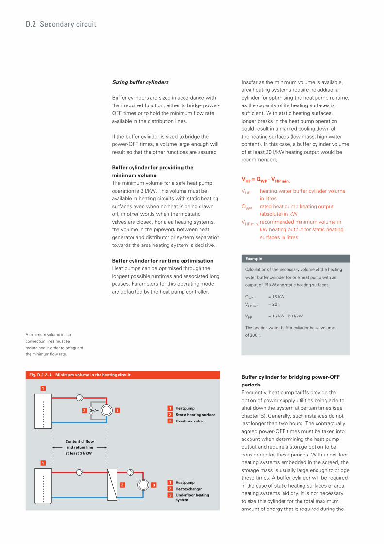
D.2 Secondary circuit
Sizing buffer cylinders
Buffer cylinders are sized in accordance with
their required function, either to bridge power-
OFF times or to hold the minimum flow rate
available in the distribution lines.
If the buffer cylinder is sized to bridge the
power-OFF times, a volume large enough will
result so that the other functions are assured.
Buffer cylinder for providing the
minimum volume
The minimum volume for a safe heat pump
operation is 3 l/kW. This volume must be
available in heating circuits with static heating
surfaces even when no heat is being drawn
off, in other words when thermostatic
valves are closed. For area heating systems,
the volume in the pipework between heat
generator and distributor or system separation
towards the area heating system is decisive.
Buffer cylinder for runtime optimisation
Heat pumps can be optimised through the
longest possible runtimes and associated long
pauses. Parameters for this operating mode
are defaulted by the heat pump controller.
Insofar as the minimum volume is available,
area heating systems require no additional
cylinder for optimising the heat pump runtime,
as the capacity of its heating surfaces is
sufficient. With static heating surfaces,
longer breaks in the heat pump operation
could result in a marked cooling down of
the heating surfaces (low mass, high water
content). In this case, a buffer cylinder volume
of at least 20 l/kW heating output would be
recommended.
VHP = QWP · VHP min.
VHP heating water buffer cylinder volume
in litres
QWP rated heat pump heating output
(absolute) in kW
VHP min. recommended minimum volume in
kW heating output for static heating
surfaces in litres
22 1 Heat pump
Static heating surface
Overflow valve
1
Content of flow
and return line
at least 3 l/kW
2
1
2
1 Heat pump
Heat exchanger
Underfloor heating system
3
3
3
3
Fig. D.2.2–4 Minimum volume in the heating circuit
Calculation of the necessary volume of the heating
water buffer cylinder for one heat pump with an
output of 15 kW and static heating surfaces:
QWP = 15 kW
VHP min. = 20 l
VHP = 15 kW · 20 l/kW
The heating water buffer cylinder has a volume
of 300 l.
Example
Buffer cylinder for bridging power-OFF
periods
Frequently, heat pump tariffs provide the
option of power supply utilities being able to
shut down the system at certain times (see
chapter B). Generally, such instances do not
last longer than two hours. The contractually
agreed power-OFF times must be taken into
account when determining the heat pump
output and require a storage option to be
considered for these periods. With underfloor
heating systems embedded in the screed, the
storage mass is usually large enough to bridge
these times. A buffer cylinder will be required
in the case of static heating surfaces or area
heating systems laid dry. It is not necessary
to size this cylinder for the total maximum
amount of energy that is required during the
A minimum volume in the
connection lines must be
maintained in order to safeguard
the minimum flow rate.
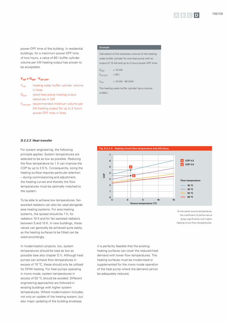
108/109
Fig. D.2.2–5 Heating circuit flow temperature and efficiency
Flow temperature:
35 °C
45 °C
55 °C
60 °C-5 0 10 155
7
6
5
3
4
2
1
0
Source temperature (°C)
CO
P
AB
B
A COP 4.5
COP 3.6
power-OFF time of the building. In residential
buildings, for a maximum power-OFF time
of two hours, a value of 60 l buffer cylinder
volume per kW heating output has proven to
be acceptable.
VHP = QWP · VHP OFF
VHP heating water buffer cylinder volume
in litres
QWP rated heat pump heating output
(absolute) in kW
VHP OFF recommended minimum volume per
kW heating output for up to 2 hours
power-OFF time in litres
Calculation of the necessary volume of the heating
water buffer cylinder for one heat pump with an
output of 15 kW and up to 2 hours power-OFF time.
QWP = 15 kW
VHP OFF = 60 l
VHP = 15 kW · 60 l/kW
The heating water buffer cylinder has a volume
of 900 l.
D.2.2.3 Heat transfer
For system engineering, the following
principle applies: System temperatures are
selected to be as low as possible. Reducing
the flow temperature by 1 K can improve the
COP by up to 2.5 %. Consequently, sizing the
heating surface requires particular attention
– during commissioning and adjustment,
the heating curves and thereby the flow
temperatures must be optimally matched to
the system.
To be able to achieve low temperatures, fan-
assisted radiators can also be used alongside
area heating systems. For area heating
systems, the spread should be 7 K, for
radiators 10 K and for fan-assisted radiators
between 5 and 10 K. In new buildings, these
values can generally be achieved quite easily,
as the heating surfaces to be fitted can be
sized accordingly.
In modernisation projects, too, system
temperatures should be kept as low as
possible (see also chapter D.1). Although heat
pumps can achieve flow temperatures in
excess of 70 °C, these should only be utilised
for DHW heating. For heat pumps operating
in mono mode, system temperatures in
excess of 55 °C should be avoided. Different
engineering approaches are followed in
existing buildings with higher system
temperatures. Where modernisation includes,
not only an update of the heating system, but
also major updating of the building envelope,
Example
At the same source temperature,
the coefficient of performance
drops significantly with higher
heating circuit flow temperatures.
it is perfectly feasible that the existing
heating surfaces can cover the reduced heat
demand with lower flow temperatures. The
heating surfaces must be modernised or
supplemented for the mono mode operation
of the heat pump where the demand cannot
be adequately reduced.
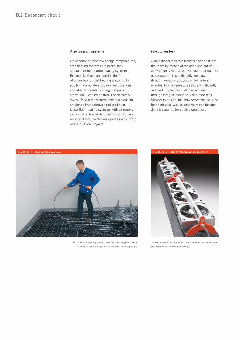
D.2 Secondary circuit
Area heating systems
On account of their low design temperatures,
area heating systems are particularly
suitable for heat pump heating systems.
Essentially, these are used in the form
of underfloor or wall heating systems. In
addition, complete structural sections – as
so-called "concrete building component
activation" – can be heated. The relatively
low surface temperatures create a pleasant
ambient climate through radiated heat.
Underfloor heating systems with extremely
low installed height that can be installed on
existing floors, were developed especially for
modernisation projects.
Fan convectors
Conventional radiators transfer their heat into
the room by means of radiation and natural
convection. With fan convectors, heat transfer
by convection is significantly increased
through forced circulation, which in turn
enables flow temperatures to be significantly
reduced. Forced circulation is achieved
through integral, electrically operated fans.
Subject to design, fan convectors can be used
for heating, as well as cooling. A condensate
drain is required for cooling operation.
Fig. D.2.2–6 Area heating systems Fig. D.2.2–7 Ultra low temperature radiators
An underfloor heating system enables low temperatures in
the heating circuit that are favourable for heat pumps.
On account of their higher heat transfer rate, fan convectors
also enable low flow temperatures.
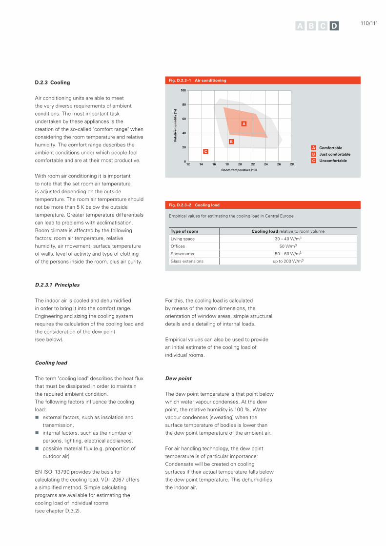
110/111
D.2.3 Cooling
Air conditioning units are able to meet
the very diverse requirements of ambient
conditions. The most important task
undertaken by these appliances is the
creation of the so-called "comfort range" when
considering the room temperature and relative
humidity. The comfort range describes the
ambient conditions under which people feel
comfortable and are at their most productive.
With room air conditioning it is important
to note that the set room air temperature
is adjusted depending on the outside
temperature. The room air temperature should
not be more than 5 K below the outside
temperature. Greater temperature differentials
can lead to problems with acclimatisation.
Room climate is affected by the following
factors: room air temperature, relative
humidity, air movement, surface temperature
of walls, level of activity and type of clothing
of the persons inside the room, plus air purity.
D.2.3.1 Principles
The indoor air is cooled and dehumidified
in order to bring it into the comfort range.
Engineering and sizing the cooling system
requires the calculation of the cooling load and
the consideration of the dew point
(see below).
Cooling load
The term "cooling load" describes the heat flux
that must be dissipated in order to maintain
the required ambient condition.
The following factors influence the cooling
load:
external factors, such as insolation and
transmission,
internal factors, such as the number of
persons, lighting, electrical appliances,
possible material flux (e.g. proportion of
outdoor air).
EN ISO 13790 provides the basis for
calculating the cooling load, VDI 2067 offers
a simplified method. Simple calculating
programs are available for estimating the
cooling load of individual rooms
(see chapter D.3.2).
Fig. D.2.3–1 Air conditioning
A
A
B
BC
C
Comfortable
Just comfortable
Uncomfortable12 14 16 18 22 24 26 28
Room temperature (°C)
20
Rel
ativ
e h
um
idit
y (%
)
100
80
60
40
20
0
For this, the cooling load is calculated
by means of the room dimensions, the
orientation of window areas, simple structural
details and a detailing of internal loads.
Empirical values can also be used to provide
an initial estimate of the cooling load of
individual rooms.
Dew point
The dew point temperature is that point below
which water vapour condenses. At the dew
point, the relative humidity is 100 %. Water
vapour condenses (sweating) when the
surface temperature of bodies is lower than
the dew point temperature of the ambient air.
For air handling technology, the dew point
temperature is of particular importance:
Condensate will be created on cooling
surfaces if their actual temperature falls below
the dew point temperature. This dehumidifies
the indoor air.
Empirical values for estimating the cooling load in Central Europe
Type of room Cooling load relative to room volume
Living space 30 – 40 W/m3
Offices 50 W/m3
Showrooms 50 – 60 W/m3
Glass extensions up to 200 W/m3
Fig. D.2.3–2 Cooling load
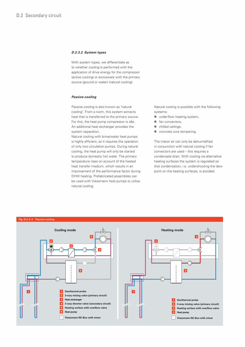
D.2 Secondary circuit
D.2.3.2 System types
With system types, we differentiate as
to whether cooling is performed with the
application of drive energy for the compressor
(active cooling) or exclusively with the primary
source (ground or water) (natural cooling).
Passive cooling
Passive cooling is also known as "natural
cooling". From a room, this system extracts
heat that is transferred to the primary source.
For this, the heat pump compressor is idle.
An additional heat exchanger provides the
system separation.
Natural cooling with brine/water heat pumps
is highly efficient, as it requires the operation
of only two circulation pumps. During natural
cooling, the heat pump will only be started
to produce domestic hot water. The primary
temperature rises on account of the heated
heat transfer medium, which results in an
improvement of the performance factor during
DHW heating. Prefabricated assemblies can
be used with Viessmann heat pumps to utilise
natural cooling.
Natural cooling is possible with the following
systems:
underfloor heating system,
fan convectors,
chilled ceilings,
concrete core tempering.
The indoor air can only be dehumidified
in conjunction with natural cooling if fan
convectors are used – this requires a
condensate drain. With cooling via alternative
heating surfaces the system is regulated so
that condensation, i.e. undershooting the dew
point on the heating surfaces, is avoided.
5
6
2
1 Geothermal probe
3-way mixing valve (primary circuit)
Heat exchanger
3-way diverter valve (secondary circuit)
Heating surface with overflow valve
Heat pump
Viessmann NC-Box with mixer
3
4
4
2
1 Geothermal probe
3-way mixing valve (primary circuit)
Heating surface with overflow valve
Heat pump
Viessmann NC-Box with mixer
3
Cooling mode Heating mode
5
6
1
3
3
2
1
4
2
4
Fig. D.2.3–3 Passive cooling
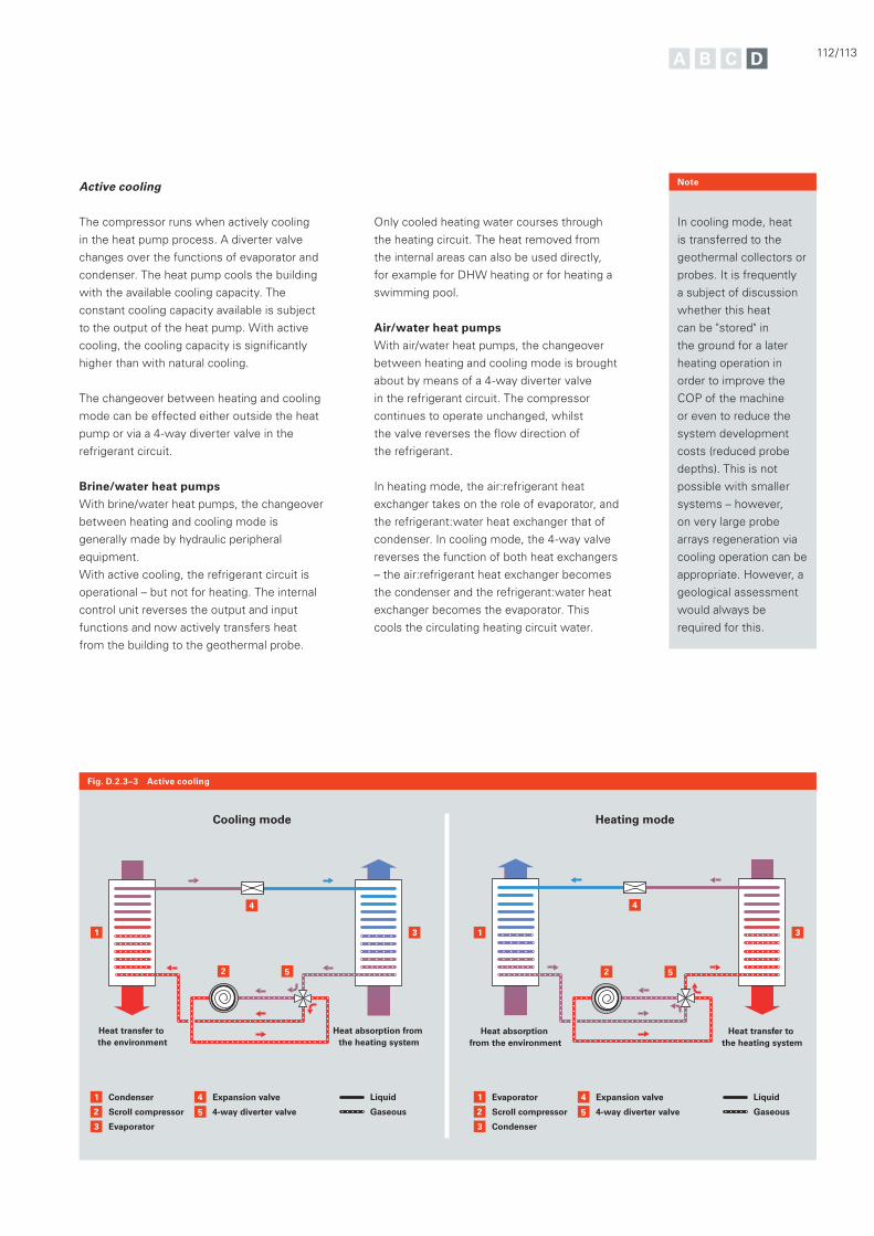
112/113
Active cooling
The compressor runs when actively cooling
in the heat pump process. A diverter valve
changes over the functions of evaporator and
condenser. The heat pump cools the building
with the available cooling capacity. The
constant cooling capacity available is subject
to the output of the heat pump. With active
cooling, the cooling capacity is significantly
higher than with natural cooling.
The changeover between heating and cooling
mode can be effected either outside the heat
pump or via a 4-way diverter valve in the
refrigerant circuit.
Brine/water heat pumps
With brine/water heat pumps, the changeover
between heating and cooling mode is
generally made by hydraulic peripheral
equipment.
With active cooling, the refrigerant circuit is
operational – but not for heating. The internal
control unit reverses the output and input
functions and now actively transfers heat
from the building to the geothermal probe.
Only cooled heating water courses through
the heating circuit. The heat removed from
the internal areas can also be used directly,
for example for DHW heating or for heating a
swimming pool.
Air/water heat pumps
With air/water heat pumps, the changeover
between heating and cooling mode is brought
about by means of a 4-way diverter valve
in the refrigerant circuit. The compressor
continues to operate unchanged, whilst
the valve reverses the flow direction of
the refrigerant.
In heating mode, the air:refrigerant heat
exchanger takes on the role of evaporator, and
the refrigerant:water heat exchanger that of
condenser. In cooling mode, the 4-way valve
reverses the function of both heat exchangers
– the air:refrigerant heat exchanger becomes
the condenser and the refrigerant:water heat
exchanger becomes the evaporator. This
cools the circulating heating circuit water.
Fig. D.2.3–3 Active cooling
In cooling mode, heat
is transferred to the
geothermal collectors or
probes. It is frequently
a subject of discussion
whether this heat
can be "stored" in
the ground for a later
heating operation in
order to improve the
COP of the machine
or even to reduce the
system development
costs (reduced probe
depths). This is not
possible with smaller
systems – however,
on very large probe
arrays regeneration via
cooling operation can be
appropriate. However, a
geological assessment
would always be
required for this.
Note
5
1 3
2
1 Evaporator
Scroll compressor
Condenser
5
Expansion valve
4-way diverter valve
4
3
Liquid
Gaseous
4
Heat transfer to the heating system
Heat absorption from the environment
2
31
Heat absorption from the heating system
2
1 Condenser
Scroll compressor
Evaporator
5
Expansion valve
4-way diverter valve
4
3
Liquid
Gaseous
52
4
Heat transfer to the environment
Cooling mode Heating mode
D.2 Secondary circuit
D.2.3.3 Cooling transfer
The cooling capacity can be transferred
into the internal space by various systems.
When planning and selecting these systems,
building characteristics (underfloor heating
system) as well as the intended requirements
of ambient conditions (dehumidification,
ambient temperature) must be taken
into account.
Area cooling
With area cooling systems, the peripheral
areas of an interior space (ceilings, floor or
walls) are cooled. Systems that can be used
for this purpose are chilled ceilings, concrete
core tempering or cooling via the underfloor
heating system. With all area cooling
systems, the dew point temperature must not
be undershot on any of the said surfaces to
prevent condensation. Area cooling systems
cannot provide dehumidification for the indoor
air, which must be provided by additional
systems, if required.
If the indoor air is not being dehumidified, the
relative humidity increases with falling room
temperature – which can result in a reduction
of comfort.
Area cooling systems are frequently
referred to as "silent cooling" as they
are frequently implemented without fan
assistance. However, there are now also
fan-assisted systems that facilitate a higher
cooling capacity.
It is now often the case that the underfloor
heating system in smaller buildings is also
used as a cooling system. For this, cold
water is pumped through the pipework of the
underfloor heating system, thereby cooling
the floor and tempering the room. With this
system, up to 25 W/m² can be transferred –
subject to the individual case, this equates
approximately to one quarter of the total
cooling load.
Cooling via fan convectors
To achieve an higher gain in comfort, cooling
with fan convectors offers the option of
cooling and dehumidifying the indoor air. Cold
water at a temperature below the dew point
flows through the fan convectors, where it is
channelled through a finned heat exchanger.
Indoor air is routed across this heat exchanger
under fan assistance. This cools the indoor air
and the flowing water heats up. Condensate
forms on the heat exchanger surface which
must be routed via the condensate pan.
Please note: The connection lines to the fan
convector must be insulated with vapour
diffusion-proof material to prevent condensate
forming on the pipes.
Fan convectors can be implemented as 2-line
or 4-line versions. In the 2-line system, cold
water flows through the heat exchanger for
cooling operation; when heating is required,
hot water flows through the same exchanger.
In 4-line systems, the fan convector features
two separate heat exchangers – one for cold
water in cooling mode and one for hot water
in heating mode.
For sizing fan convectors, the required
room temperature and the cold water inlet
temperature play major roles. The greater the
differential between these two temperatures,
the more cooling capacity the fan convector
will transfer. The reverse applies as follows:
A smaller appliance may be used in the case
of a large differential between the cold water
inlet and the room temperature.

114/115
Cooling via ventilation systems
Ventilation systems can also provide cooling.
However, the achievable cooling capacity for
a single room is limited by the temperature
at which the air is blown into the room. This
temperature should not fall below 14 °C in
order to avoid the unpleasant perceptions of
draughts. This can provide a cooling capacity
of approximately 5 W per 1 m³/h air flow
brought into the room.
For this type of application, a cooling bank
is fitted into the ventilation unit which cools
the air flowing through it. If dehumidification
of the ambient air is required, the surface
temperature of the cooling bank will be
below the dew point – this condensates the
water in the air flow. With this application,
an additional water separator, and possibly
a reheating bank, may be required in the
central ventilation unit. In addition, more
stringent hygiene requirements apply to the
maintenance of the appliance.
The dehumidification function is omitted
for this reason in ventilation appliances for
controlled domestic ventilation.

D.3 Output calculation and engineering aids
One particular aspect to remember when
sizing heat pump systems is the consideration
of power-OFF times that may be applied
subject to special electricity tariffs.
For determining output, Viessmann offers its
trade partners a sizing program that calculates
not only the heat pump parameters, but also
those of a suitable DHW cylinder.
As an additional engineering aid, Viessmann
heat pump system sizing aids and the
Viessmann scheme browser are also
available. These enable efficient heat pump
systems to be engineered step by step and
with great reliability.
Output calculation and engineering aids
The required output of a heat pump is determined in the same way as that of any other heat generator. In mono mode or in mono energetic operation, the heat pump must be sized in accordance with DIN EN 12831 as the sole heat generator.

116/117
D.3.1 Determining the heat pump output
How to calculate DHW demand and
requirements to be observed regarding heat
transfer to rooms have already been described
in chapter D.2.
In order to be able to determine the heat
pump output, possible power-OFF times
imposed by the power supply utility must be
taken into account, alongside the heat load
and the DHW demand.
In the case of special power tariffs for heat
pumps, the power supply utility has the right
to interrupt the power supply for up to 2 hours
up to three times per day – these "out times"
need to flow into the calculation of the daily
building energy statement.
Under the climatic
conditions prevalent
in Germany, practical
experience has shown
that for power-OFF
times of up to 2 hours
per day, no supplement
needs to be applied to
the heat pump output,
in other words it can be
sized purely on the basis
of the building heat load.
Although this makes it
theoretically possible
that some of the rooms
of the building will
fail to be held at the
target temperature
consistently, in normal
heating operation in
residential buildings this
is highly unlikely.
Note
The building heat load is 12 kW.
The power-OFF times are 3 x 2 hours.
Daily possible heating hours:
24 h – 6 h power-OFF time = 18 h
Daily heat load of the building:
12 kW · 24 h = 288 kWh
Heat pump heating output:
288 kWh / 18 h = 16 kW
The building heat load is 12 kW. The output required
for DHW heating is 2 kW.
20 % of the heat load is 12 kW · 0.2 = 2.4 kW
2 kW < 2.4 kW
No supplement for DHW heating is required.
Example
Example
The size of the heat pump in mono mode
systems is determined in two steps:
Step 1: Determining the daily heat demand in
the design state
Step 2: Dividing the daily heat demand
by the number of heating hours that are
actually possible
DHW heating will only be taken into
consideration when sizing the heat pump, if
the required output for DHW heating during
heat-up times (see chapter D.2.1) is higher
than 20 % of the heat load.
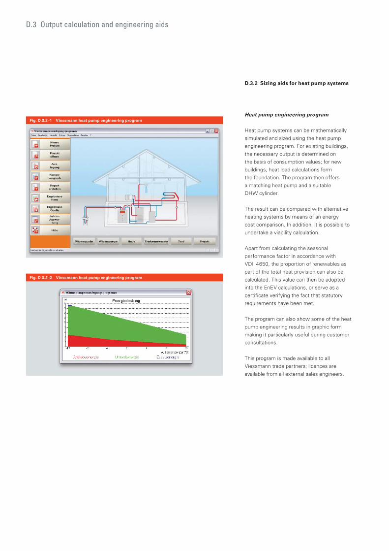
D.3 Output calculation and engineering aids
D.3.2 Sizing aids for heat pump systems
Heat pump engineering program
Heat pump systems can be mathematically
simulated and sized using the heat pump
engineering program. For existing buildings,
the necessary output is determined on
the basis of consumption values; for new
buildings, heat load calculations form
the foundation. The program then offers
a matching heat pump and a suitable
DHW cylinder.
The result can be compared with alternative
heating systems by means of an energy
cost comparison. In addition, it is possible to
undertake a viability calculation.
Apart from calculating the seasonal
performance factor in accordance with
VDI 4650, the proportion of renewables as
part of the total heat provision can also be
calculated. This value can then be adopted
into the EnEV calculations, or serve as a
certificate verifying the fact that statutory
requirements have been met.
The program can also show some of the heat
pump engineering results in graphic form
making it particularly useful during customer
consultations.
This program is made available to all
Viessmann trade partners; licences are
available from all external sales engineers.
Fig. D.3.2–1 Viessmann heat pump engineering program
Fig. D.3.2–2 Viessmann heat pump engineering program
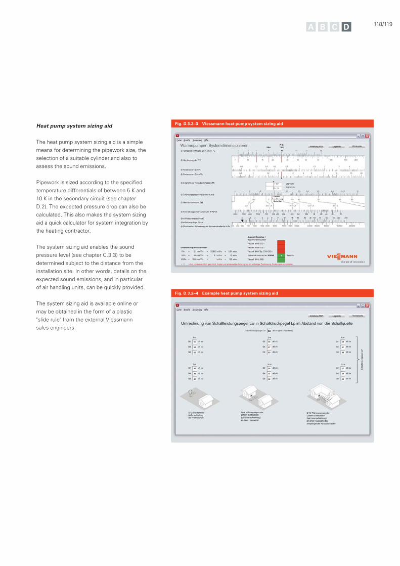
118/119
Heat pump system sizing aid
The heat pump system sizing aid is a simple
means for determining the pipework size, the
selection of a suitable cylinder and also to
assess the sound emissions.
Pipework is sized according to the specified
temperature differentials of between 5 K and
10 K in the secondary circuit (see chapter
D.2). The expected pressure drop can also be
calculated. This also makes the system sizing
aid a quick calculator for system integration by
the heating contractor.
The system sizing aid enables the sound
pressure level (see chapter C.3.3) to be
determined subject to the distance from the
installation site. In other words, details on the
expected sound emissions, and in particular
of air handling units, can be quickly provided.
The system sizing aid is available online or
may be obtained in the form of a plastic
"slide rule" from the external Viessmann
sales engineers.
Fig. D.3.2–3 Viessmann heat pump system sizing aid
Fig. D.3.2–4 Example heat pump system sizing aid
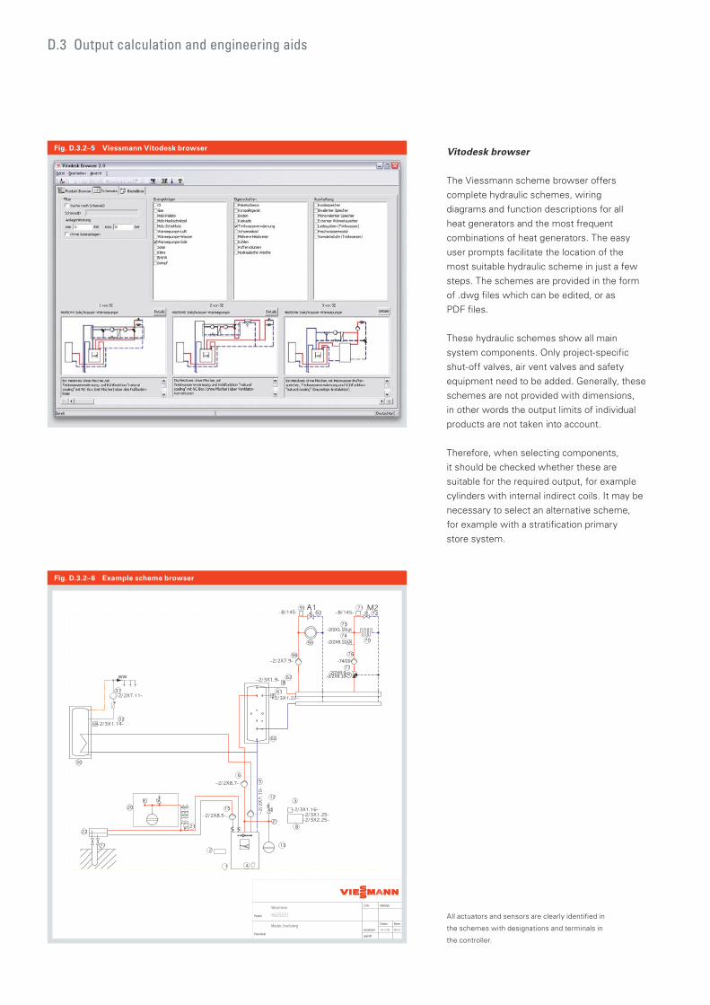
Fig. D.3.2–6 Example scheme browser
Projekt
Plan-Inhaltgeprüft
bearbeitet
Datum Name
Z.-Nr. MaßstabViessmann
4605051
Master_hoch.dwg16.11.09 XKruT
P
P
-2/3X1.10-
-2/2X8.11-
-74/20-
-2/2X8.9--2/2X8.10-WW
D.3 Output calculation and engineering aids
Vitodesk browser
The Viessmann scheme browser offers
complete hydraulic schemes, wiring
diagrams and function descriptions for all
heat generators and the most frequent
combinations of heat generators. The easy
user prompts facilitate the location of the
most suitable hydraulic scheme in just a few
steps. The schemes are provided in the form
of .dwg files which can be edited, or as
PDF files.
These hydraulic schemes show all main
system components. Only project-specific
shut-off valves, air vent valves and safety
equipment need to be added. Generally, these
schemes are not provided with dimensions,
in other words the output limits of individual
products are not taken into account.
Therefore, when selecting components,
it should be checked whether these are
suitable for the required output, for example
cylinders with internal indirect coils. It may be
necessary to select an alternative scheme,
for example with a stratification primary
store system.
Fig. D.3.2–5 Viessmann Vitodesk browser
All actuators and sensors are clearly identified in
the schemes with designations and terminals in
the controller.

120/121
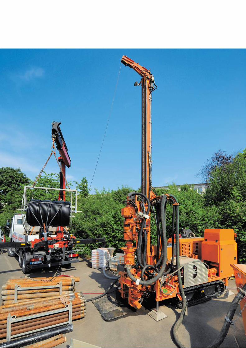

122/123
The most important steps necessary for a
successful engineering and installation project
are listed as a brief summary. Those points
that should be taken into consideration as
part of the engineering process have been
collated.
In order to do justice to the requirements
and expectations a heat pump demands,
regular inspection and optimisation are always
recommended. The references to inspection
and optimisation show what matters most.
124 The path to an efficient heat pump system
130 Information on inspection and optimisation
132 Keyword index
Appendix
In addition to the technical information provided for engineering purposes, this appendix includes information that may be useful and appropriate for practical applications.
Use the keyword index of essential terms to
make this manual a useful professional guide
for everyday use.
The path to an efficient heat pump system
When planning a solar thermal system, it is often just as important to look at its viability as its technical aspects.
Appendix – The path to an efficient heat pump system
A decision in favour of a heat pump
system requires competent and extensive
consultation – this is particularly the case
for modernisation projects. Generally
speaking, as heat pump systems require a
greater level of investment than conventional
heat generators, in our experience, the
expectations of potential investors are
correspondingly high, particularly regarding
the ecology and efficiency of the intended
system. Sufficient time needs to be
scheduled during the consultation to
discuss these expectations adequately,
so that technological limits, too, can be
discussed. Heat pumps are heat generators,
how much they can save depends largely
on the prevailing operating conditions.
Disappointment can be avoided if the
interested parties can be made familiar with
the relevant general conditions concerning
their investment as soon as possible.
In order to be able to carry out a professional
consultation, extensive data on the actual
conditions in the existing building need to
be recorded in the case of modernisation
projects. This includes, not only the building
characteristics, but also any installed heating
system. The existing heating surface sizes,
flow temperatures and pipework dimensions
in particular, need to be considered, too.
Using the average annual energy consumption
figures and the heat pump engineering
program, you can provide an initial overview
of appropriate system options, the costs to be
expected and the potential savings.
Chapter B.3 provides detailed information on
the viability calculation.
1. Recording the current situation and the result of customer consultations

124/125
2. Calculating the heat load
3. Determination of the system temperature in the heating circuit
System engineering starts with calculating the
heat load. This is essential both for new build
and modernisation projects alike, in order to
achieve an optimum engineering of the heat
pump system.
DIN EN 12831 forms the basis for
determining the heat load. The resulting value
would be the maximum heat load of the
building that must be covered by the output of
the heat generator.
Deriving the heat load from the EnEV energy
performance certificate of the building is not
possible.
The energy performance certificate indicates
the final energy demand, amongst others.
This can be matched with the results of the
special engineering required for sizing a heat
pump system.
In new build, where no reference
consumptions can be known from previous
years, the final energy demand from the
energy performance certificate serves as a
basis for engineering. It may be used, when
engineering ground-coupled heat pumps, to
determine the extraction rate as well as the
amount of heat to be extracted.
The lower the system temperature, the higher
the efficiency of the heating system. Every
increase in flow temperature by 1 K reduces
the heat pump COP by 2.5 %.
Where a heat pump system is intended to
be used in new build projects, generally
area heating systems will be used in order
to achieve the lowest possible system
temperatures and consequently a high degree
of energy efficiency.
Existing static heating surfaces offer a
worst COP and, as a result, poorer seasonal
performance factors, since their flow
temperatures are higher than those of area
heating systems. To achieve the maximum
possible efficiency in modernisation projects,
the following steps should be taken in order
to keep the heating system flow temperatures
reliably below 55 °C:
Generally, heating surfaces should be
re-calculated.
The flow temperature demand
of the individual heating surfaces
must be balanced.
Individual heating surfaces with
high temperature demand must be
replaced or supplemented.
In any case, a heating circuit calculation and
hydraulic balancing should be included in the
quotation for any modernisation project.
Knowing the heat load, the annual energy
demand and the system temperatures are the
essential foundation for further engineering
steps.
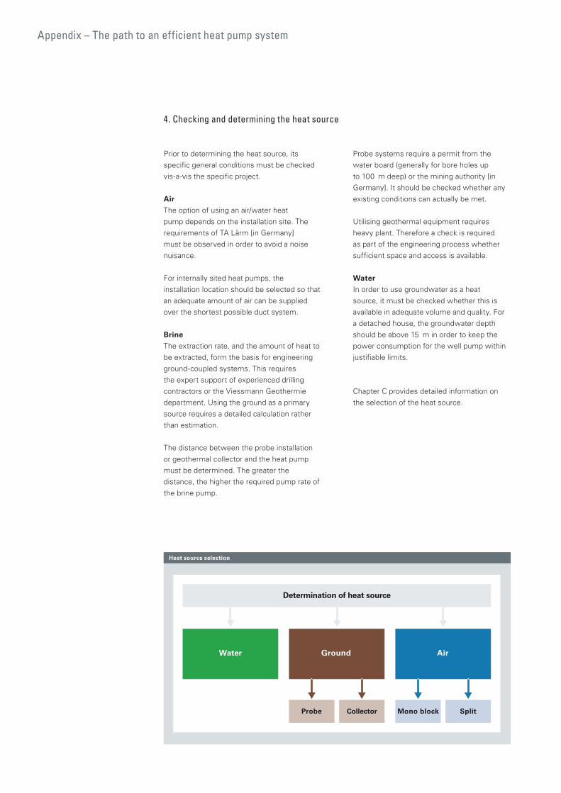
Appendix – The path to an efficient heat pump system
4. Checking and determining the heat source
Prior to determining the heat source, its
specific general conditions must be checked
vis-a-vis the specific project.
Air
The option of using an air/water heat
pump depends on the installation site. The
requirements of TA Lärm [in Germany]
must be observed in order to avoid a noise
nuisance.
For internally sited heat pumps, the
installation location should be selected so that
an adequate amount of air can be supplied
over the shortest possible duct system.
Brine
The extraction rate, and the amount of heat to
be extracted, form the basis for engineering
ground-coupled systems. This requires
the expert support of experienced drilling
contractors or the Viessmann Geothermie
department. Using the ground as a primary
source requires a detailed calculation rather
than estimation.
The distance between the probe installation
or geothermal collector and the heat pump
must be determined. The greater the
distance, the higher the required pump rate of
the brine pump.
Probe systems require a permit from the
water board (generally for bore holes up
to 100 m deep) or the mining authority [in
Germany]. It should be checked whether any
existing conditions can actually be met.
Utilising geothermal equipment requires
heavy plant. Therefore a check is required
as part of the engineering process whether
sufficient space and access is available.
Water
In order to use groundwater as a heat
source, it must be checked whether this is
available in adequate volume and quality. For
a detached house, the groundwater depth
should be above 15 m in order to keep the
power consumption for the well pump within
justifiable limits.
Chapter C provides detailed information on
the selection of the heat source.
Determination of heat source
Water Ground Air
Probe Collector Mono block Split
Heat source selection
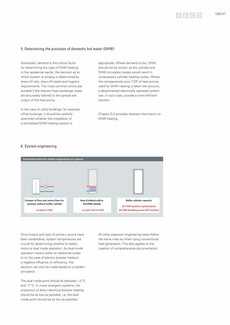
126/127
5. Determining the provision of domestic hot water (DHW)
6. System engineering
Essentially, demand is the critical factor
for determining the type of DHW heating.
In the residential sector, the decision as to
which system to employ is determined by
draw-off rate, draw-off peaks and hygiene
requirements. The most common errors are
avoided if the relevant heat exchanger areas
are accurately tailored to the spread and
output of the heat pump.
In the case of utility buildings, for example
office buildings, it should be carefully
examined whether the installation of
a centralised DHW heating system is
appropriate. Where demand is low, DHW
should not be stored, as the cylinder and
DHW circulation losses would result in
unnecessary cylinder heating cycles. Where
the comparatively poor COP of heat pumps
used for DHW heating is taken into account,
a decentralised electrically operated system
can, in such case, provide a more efficient
solution.
Chapter D.2 provides detailed information on
DHW heating.
Once output and type of primary source have
been established, system temperatures are
crucial for determining whether to select
mono or dual mode operation. As dual mode
operation means either an additional outlay
or (in the case of electric booster heaters)
a negative influence on efficiency, the
decision can only be made based on a system
simulation.
The dual mode point should lie between –3 °C
and –7 °C. In mono energetic systems, the
proportion of direct electrical booster heating
should be as low as possible, i.e. the dual
mode point should be as low as possible.
All other pipework engineering steps follow
the same rules as when using conventional
heat generators. This also applies to the
creation of comprehensive documentation.
Important points for system engineering at a glance
Area of indirect coils in
the DHW cylinder
at least 0.25 m²/kW
Buffer cylinder capacity
20 l/kW (runtime optimisation)
60 l/kW (bridging power-OFF periods)
Content of flow and return lines for
systems without buffer cylinder
at least 3 l/kW
7. Installation and commissioning
8. Instructions
As long as no work on the refrigerant circuit
is necessary, the requirements for the
installation of a heat pump correspond to
those of other heat generators, where trade
expertise is concerned.
KlimaChem.VO (ordinance on climate
protection from changes through emissions
of certain fluorinated greenhouse gases)
specifies the requirement for competent
personnel when installing refrigerant lines for
split heat pumps. Viessmann offers relevant
technical courses.
The system efficiency will be proven in its
daily operation. This makes commissioning,
with comprehensive function checks on the
intended properties such as those following,
essential:
Advanced heat pumps are safe to operate,
and as easy to understand from the
operations viewpoint, as any systems
employing conventional heat generators.
However, efficient operation requires
a utilisation that calls for a certain
understanding and care, particularly where
system temperatures are concerned.
Changing individual operating parameters may
have an impact on efficiency – this must be
made clear to system users. It is appropriate
to set parameters, such as set temperatures
and power-OFF times at the controller
together with users whilst they are being
introduced to the system.
Hydraulic balancing of primary
and secondary circuits with checking
intended flow rates.
Checking the design DHW temperature.
Setting the heating curves in accordance
with the design system temperature.
Setting control parameters of the existing
hydraulics.
Checking fluids, such as the brine
concentration in the case of brine/water
heat pumps.
The correlation with other heating system
components should be explained. In order to
maintain an efficient operation, it is necessary
that
the control of the entire system is
regulated by the heat pump control unit in
dual mode systems,
room temperature controllers, including
thermostats, are operated in a subordinate
manner,
DHW switching times are set as near to
times of consumption as possible.
Appendix – The path to an efficient heat pump system

128/129
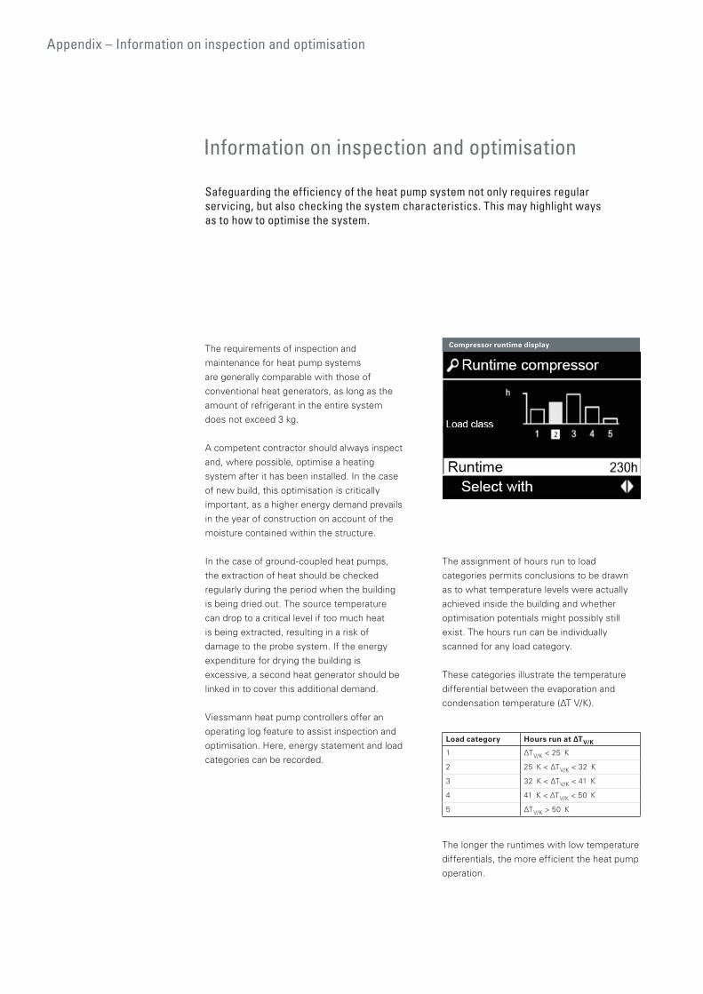
Appendix – Information on inspection and optimisation
Information on inspection and optimisation
Safeguarding the efficiency of the heat pump system not only requires regular servicing, but also checking the system characteristics. This may highlight ways as to how to optimise the system.
The requirements of inspection and
maintenance for heat pump systems
are generally comparable with those of
conventional heat generators, as long as the
amount of refrigerant in the entire system
does not exceed 3 kg.
A competent contractor should always inspect
and, where possible, optimise a heating
system after it has been installed. In the case
of new build, this optimisation is critically
important, as a higher energy demand prevails
in the year of construction on account of the
moisture contained within the structure.
In the case of ground-coupled heat pumps,
the extraction of heat should be checked
regularly during the period when the building
is being dried out. The source temperature
can drop to a critical level if too much heat
is being extracted, resulting in a risk of
damage to the probe system. If the energy
expenditure for drying the building is
excessive, a second heat generator should be
linked in to cover this additional demand.
Viessmann heat pump controllers offer an
operating log feature to assist inspection and
optimisation. Here, energy statement and load
categories can be recorded.
Compressor runtime display
The assignment of hours run to load
categories permits conclusions to be drawn
as to what temperature levels were actually
achieved inside the building and whether
optimisation potentials might possibly still
exist. The hours run can be individually
scanned for any load category.
These categories illustrate the temperature
differential between the evaporation and
condensation temperature (ΔT V/K).
Load category Hours run at ΔTV/K
1 ΔTV/K < 25 K
2 25 K < ΔTV/K < 32 K
3 32 K < ΔTV/K < 41 K
4 41 K < ΔTV/K < 50 K
5 ΔTV/K > 50 K
The longer the runtimes with low temperature
differentials, the more efficient the heat pump
operation.
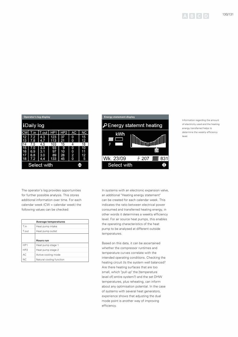
130/131
Operator's log display Energy statement display
The operator's log provides opportunities
for further possible analysis. This stores
additional information over time. For each
calendar week (CW = calendar week) the
following values can be checked:
Average temperatures
T.in Heat pump intake
T.out Heat pump outlet
Hours run
HP1 Heat pump stage 1
HP2 Heat pump stage 2
AC Active cooling mode
NC Natural cooling function
In systems with an electronic expansion valve,
an additional "Heating energy statement"
can be created for each calendar week. This
indicates the ratio between electrical power
consumed and transferred heating energy, in
other words it determines a weekly efficiency
level. For air source heat pumps, this enables
the operating characteristics of the heat
pump to be analysed at different outside
temperatures.
Based on this data, it can be ascertained
whether the compressor runtimes and
temperature curves correlate with the
intended operating conditions. Checking the
heating circuit (Is the system well balanced?
Are there heating surfaces that are too
small, which "pull up" the [temperature
level of] entire system?) and the set DHW
temperatures, plus reheating, can inform
about any optimisation potential. In the case
of systems with several heat generators,
experience shows that adjusting the dual
mode point is another way of improving
efficiency.
Information regarding the amount
of electricity used and the heating
energy transferred helps to
determine the weekly efficiency
level.
Absorption 43
Absorption heat pump 43
Acoustic engineering 79 ff.
Active cooling 113
Adsorption 43
Adsorption heat pump 45
Air routing 82
Air/water heat pumps 37
Sizing/engineering 76 ff.
Amortisation 61
Appliance expenditure of energy value 58
Area cooling 114
Area heating systems 110
Air duct 82 f.
BDH information sheet no. 43 67 f.
Biomass 91
Boreholes 35
Booster heat exchanger 105
Bridging power-OFF periods 108
Brine 33
Brine/water heat pump 33
Sizing/engineering 64 ff.
Buffer cylinder 106 ff.
Buffer cylinders in series 107
Carnot 17
Cascade systems 89
Chilled ceilings 114
Combi cylinder 104
Commissioning 128
Compression 20
Compression heat pump 43
Compressor 25
Condensation heat 19
Condenser 30
Condensing 19 f.
Cooling 111
Via fan convectors 114
Via ventilation system 115
Cooling bank 115
Cooling load 111
Cooling transfer 114 f.
COP 21
Cost, consumption-dependent 61
Coverage 88
Cylinder primary pump 104
Day load profile 52
Dehumidification 112
Desorption 45
Determining demand (DHW) 94 ff.
Dew point 111
DHW cylinder 102
DHW heating 93
DHW heating 100 ff.
Dual mode 100
Mono energetic 100
Mono mode 100
DHW heat pumps 101
DHW hygiene 93
Directivity 80
DIN 4701-10 88
Draw-off pattern 94
Drive energy, electrical 48
Drying out buildings 130
Dual mode point 87
DVGW de of Practice W 1 93
Eco design guideline 59
Economy 60
Efficiency 21
Electronics 28
EN 450 94
Energetic assessment 50
Energy performance certificate 57
Energy Saving Ordinance (EnEV) 57
Engineering aids 116 ff.
Enthalpy 20
Appendix – Keyword index
Keyword index
132/133
EPBD (Energy Performance
of Buildings Directive) 59
ErP (Energy related Products) 59
Ethylene glycol 69
Evaporation 19 f.
Evaporation enthalpy 19
Evaporator 29
EVI (Enhanced Vapour Injection) 27
Expansion 20
Expansion valve 28
Extract air mode 101
Extraction rate warranty 35
Fan convector 110
Final energy demand 57
Fixed speed compressor 77
Flow rate (brine circuit) 70
Flow temperature 109
Fluorine hydrocarbons 31
Freshwater systems 105
Geothermal collector 33 f.
Geothermal probe 35 f.
Groundwater 37
Halogenes 31
Heat exchanger 29
Coaxial heat exchanger 29
Fin heat exchanger 29
Plate heat exchanger 29
Heat extraction rates 33
Heat pump electricity tariffs 52
Heat pump engineering program 118
Heat pump system scaler 119
Heat source 33 ff.
Ground 33 ff.
Outdoor air 37
Solar backed-up absorber 39
Water 37
Waste heat 38
Heat transfer 109
Heat transfer medium 69
Heating curves 109
Heating hydraulics 106
Heating lance 103
Heating operation 106 ff.
Heating rod 87
Hot gas separation 30
Hydraulic schemes 120
Icing up 29
Inspection 123 ff.
Installation 128
Instruction 128
Intake temperature 115
Intermediate circuit 72 f.
Intermediate vapour injection 27
Inverter technology 26
Investment 61
Isotherm 19
Kelvin 17
Load categories 130
Load profile 94
Log p,h diagram 20
Low temperature radiator 110
Market development of heat pumps 49
Minimum clearances 81
Minimum volume (buffer cylinder) 108
Natural cooling 112
Operating modes 86 ff.
Alternative 88
Dual mode 87
Mono mode 87
Parallel 87
Partially parallel 88
Operator's log 131
Optimisation 130 f.
Output control 26
Output determination 116 ff.
Overflow valve 107
Parallel buffer cylinder 106 ff.
Passive cooling 112
Perkins 17
Phase transition cylinder 40
Photovoltaics 54
Pre-heating stage 93
Pressure drop (brine circuit) 70
Pressure reducing valve 26
Primary circuit 24
Primary energy demand 57
Primary energy factor 50
Primary sources 32 ff.
Primary store 103
Primary store systems 103
Power consumption 48
Power mix 49
Power-Off times 52, 109
Recirculation air mode 101
Reference period 97
Refrigerant 31
Natural 31
Refrigerant circuit 19 f.
Refrigerant/distribution facility 29
Refrigerating machine 20
Refrigerant mass flow rate 28
Scheme browser 120
Scroll compressor 25
Seasonal performance factor 22
Secondary circuit 92 ff.
Silent cooling 114
Sizing/engineering 72 ff.
Sizing/engineering
Coolant 75
Geothermal collector systems 65 ff.
Geothermal probe systems 65 ff.
Groundwater 73 f.
Outdoor air 82 f.
Primary sources 63 ff.
Smart metering 53
Solar absorber 33
Solar thermal system 90
Solidification enthalpy 40
Sorption 43
Sound power level LW 79
Sound pressure level LP 79
Standard Dimension Ratio (SDR) 65
Steam engine 16
Suction gas heat exchanger 30
Surface water 37
Supply security 51 f.
Supply well 37
System engineering 85 ff.
System expenditure of energy value 58
System temperatures 109
Tank-in-Tank systems 104
Thermal compression 44
Thermal Response Test (TRT) 36
Thermostatics 28
Underfloor heating 110
VDI 40 66
VDI 50 88
Waste water heat exchanger 38
Water/water heat pump 37
Water quality 37
Wiring diagrams 120
Zeolite 45
Appendix – Keyword index

134/135
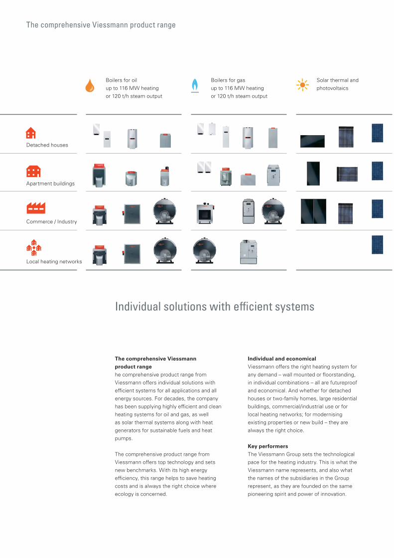
The comprehensive Viessmann product range
Individual solutions with efficient systems
The comprehensive Viessmannproduct rangehe comprehensive product range fromViessmann offers individual solutions withefficient systems for all applications and allenergy sources. For decades, the company has been supplying highly efficient and clean heating systems for oil and gas, as well as solar thermal systems along with heat generators for sustainable fuels and heat pumps.
The comprehensive product range from Viessmann offers top technology and sets new benchmarks. With its high energy efficiency, this range helps to save heating costs and is always the right choice where ecology is concerned.
Individual and economicalViessmann offers the right heating system for any demand – wall mounted or floorstanding, in individual combinations – all are futureproof and economical. And whether for detached houses or two-family homes, large residential buildings, commercial/industrial use or for local heating networks; for modernising existing properties or new build – they are always the right choice.
Key performersThe Viessmann Group sets the technological pace for the heating industry. This is what the Viessmann name represents, and also what the names of the subsidiaries in the Group represent, as they are founded on the same pioneering spirit and power of innovation.
Detached houses
Apartment buildings
Commerce / Industry
Local heating networks
Solar thermal andphotovoltaics
Boilers for oil up to 116 MW heating or 120 t/h steam output
Boilers for gas up to 116 MW heating or 120 t/h steam output
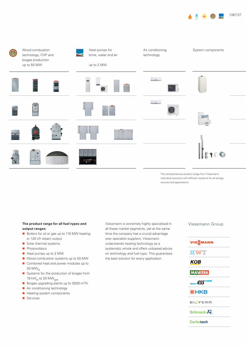
136/137
The comprehensive product range from Viessmann:
Individual solutions with efficient systems for all energy
sources and applications
Viessmann is extremely highly specialised in all these market segments, yet at the same time the company has a crucial advantage over specialist suppliers: Viessmann understands heating technology as a systematic whole and offers unbiased advice on technology and fuel type. This guarantees the best solution for every application.
The product range for all fuel types and output ranges:
Boilers for oil or gas up to 116 MW heating or 120 t/h steam output
Solar thermal systems Photovoltaics Heat pumps up to 2 MW Wood combustion systems up to 50 MW Combined heat and power modules up to
30 MWel Systems for the production of biogas from
18 kWel to 20 MWgas Biogas upgrading plants up to 3000 m3/h Air conditioning technology Heating system components Services
Air conditioningtechnology
System componentsHeat pumps forbrine, water and air
up to 2 MW
Wood combustion technology, CHP and biogas productionup to 50 MW

The comprehensive Viessmann product range
The comprehensive product range from Viessmann: Individual solutions
with efficient systems for all energy sources and applications
Detached houses Apartment buildings Commerce / Industry Local heating networks
Solar thermal and
photovoltaics
Oil boilers
Gas boilers
Wood combustion
technology, CHP, and
biogas production
Studio flats, Brandenburg,
Germany
University library, Bamberg,
Germany
Residential estate, Pfäffikon,
Switzerland
Loftcube Regional Garden
Show, Neu-Ulm, Germany
Heat pumps for
brine, water and air
HafenCity, Hamburg,
Germany
City of Tomorrow, Malmö,
Sweden
The Palm Jumeirah,
Dubai
Heliotrop Freiburg,
Germany
Residential development, Zi Wei
Garden Xi'an, China
Ameco A380 Hangar Beijing,
China
European Parliament, Strasbourg,
France
Architect's own home,
Bad Füssing, Germany
"Wohnoase" residential park in
Regensburg, Germany
Porsche Leipzig,
Germany European Parliament, Brussels,
Belgium
Detached house, Kevelaer,
Germany
Hotel Lagorai Cavalese,
Italy
Congressional Centre,
Brunstad, Norway
Monastery, St. Ottilien,
Germany
Detached house, Wiesloch,
Germany

138/139
City of Tomorrow, Malmö, Sweden
Futureproof heating technology for all requirements
Energy consumption worldwide has doubled since 1970 and will triple by 2030. The result: The fossil fuels, oil and gas, are dwindling, energy prices are on the rise and excessive CO2 emissions continue to affect our environment. Energy efficiency is a must if we want our future to be secure.
In almost every industrial nation, supplying heat to residential and commercial buildings accounts for the largest share of energy consumption – consequently it also offers the greatest savings potential. Advanced efficient heating systems from Viessmann are in use around the world, not only in many private households, but also in numerous major international projects, where they make a sizeable contribution to the efficient use of energy resources.
In these projects, Viessmann again and again faces up to the most varied challenges to supply efficient heating technology by offering innovative solutions – in historical listed buildings as well as in modern industrial complexes and the large-scale residential and industrial arena.
The company

140/141
Deutschlands nachhaltigsteProduktion 2009
Deutschlands nachhaltigsteMarke 2011
Viessmann – climate of innovation
For the particularly efficient utilisation
of energy through the innovative heat
recovery centre at the company's
main site in Allendorf/Eder,
Viessmann was rewarded with the
Energy Efficiency Award 2010.
Viessmann Group
The Viessmann brand promise conciselyexpresses all that we hope to achieve. It is our key brand message and, together with our brand label, is an identifying feature throughout the world. "Climate of innovation" is a promise on three levels: It is a commitment to a culture of innovation. It is a promise of high product utilisation and, at the same time, an obligation to protect the environment.
Comprehensive range for all fuel typesViessmann is one of the leading internationalmanufacturers of heating systems and, with its comprehensive product range, offers individual solutions in the shape of efficient systems for all applications and types of fuel. The company is now run by the third generation of the Viessmann family, and has been supplying particularly efficient and clean heating systems for several decades.
Acting in a sustainable mannerFor Viessmann, to take responsibility, means a commitment to act in a sustainable way. This means bringing ecology, economy and social responsibility into harmony with each other, ensuring that current needs are satisfied without limiting the basis for life for the generations to come.
Efficiency PlusWith the "Efficiency Plus" sustainability project that commenced in 2005, Viessmann demonstrates at its own site in Allendorf that the political goals set for 2050 with regard to climate and energy can already be achieved today with commercially available technology.
By utilising renewables and by improving the energy, material and operational efficiency we not only improve our competitiveness but also secure our production site.
Comprehensive range of products from Viessmann for every type of fuel and all output ranges
Boilers for oil and gas Solar thermal systems Photovoltaics Heat pumps Wood combustion systems Combined heat and power Biogas production plants Biogas upgrading plants Air conditioning Heating system components Services
Company details Established in: 1917 Employees: 9600 Group turnover: €1.86 billion Export share: 55 percent 24 manufacturing plants in 11 countries Sales companies and representations
in 74 countries 120 sales outlets worldwide
Viessmann was awarded the
German Sustainability Prize for the
"most sustainable production 2009"
and as being the "most sustainable
brand 2011".

Sources
Unless otherwise stated, all graphics and
photographs are from Viessmann.
A.1–3 Linde AG
A.4.1–2 Ebner OG, Sitzendorf, Austria
B.1.1–1 BDEW, AG Energiebilanzen
B.1.4–2 Solarenergie-Förderverein
Deutschland (SFV)
S. 56 Pixel – Fotolia.com
B.2.1–2 dena
S. 60 U21, Hanover
C.1.1–3 VDI 4640
C.1.1–4 VDI 4640
C.1.1–5 BDH, information sheet no. 43
D.2.1–1 DIN EN 15450
D.2.1–2 DIN EN 15450
D.2.1–3 DIN EN 15450
D.2.1–4 DIN EN 15450
Production
Technical manual – Heat pumps
Publisher
Viessmann Werke, Allendorf (Eder)
Text & Design
solarcontact, Hanover
Overall production
Grafisches Centrum Cuno, Calbe (Saale)
© 2011 Viessmann Werke

142/143

5470 699 D 03/2011
Copyright Viessmann.Duplication and alternative use only with prior written consent.Subject to technical modifications.
The Viessmann Group
D-35107 Allendorf (Eder)
Telephone +49 (0)6452 70-0
Fax +49 (0)6452 70-2780
www.viessmann.com
9440 134 GB 04/2012
Copyright Viessmann.Duplication and alternative use only with prior written consent.Subject to technical modifications.