Embed Size (px)
Citation preview

Prepared For: Kroeschell Engineering Company
Date: February 16, 2010
Job Name: Columbus AFB Dental Clinic
Trane U.S. Inc. is pleased to provide the enclosed submittal for your review and approval. Product Summary
Qty Product 1 Performance Climate Changer
Peter A Hill Trane 7100 South Madison Willowbrook, IL 60527-5505 Phone: (630) 734-3200 Fax: (630) 323-9040
The attached information describes the equipment we propose to furnish for this project, and is submitted for your approval.
Submittal
J:\JOBS\92\140860\4\sub021610.doc

Table Of Contents
Product Summary ........................................................................................................................... 1
Performance Climate Changer (Item A1) Tag Data .................................................................................................................................................. 3 Product Data ............................................................................................................................................ 3 Performance Data .................................................................................................................................... 4 Mechanical Specifications ........................................................................................................................ 6 As-Built ................................................................................................................................................... 10 Fan Curve .............................................................................................................................................. 17 Accessory .............................................................................................................................................. 19 Field Wiring ............................................................................................................................................ 24
Field Installed Options - Part/Order Number Summary Performance Climate Changer ............................................................................................................... 25

Columbus AFB Dental Clinic February 16, 2010
FLD = Furnished by Trane U.S. Inc. / Installed by Others
Equipment Submittal Page 3 of 25
Tag Data - Performance Climate Changer (Qty: 1) Item Tag(s) Qty Description Model Number
A1 AHU-1 1 Performance Climate Changer ( CSAA ) CSIA017
Product Data - Performance Climate Changer
Item: A1 Qty: 1 Tag(s): AHU-1 Unit level options Indoor unit Unit size 17 2.5in. integral base frame UL listed unit Multiple composite handles/latches 108 Unit length No marine LED lights in unit Air mixing section (Pos #1) Air mixing section Mixing box w/filter Door- left side Coil section (Pos #2) Horizontal coil Medium Stainless steel drain pan Left side - drain connection Left side - coil supply Unit coil height Cooling coil Single use coil Type "UU" coil 8 rows 99 Fin spacing Aluminum fins Delta flo H (Hi efficient) .016" (0.406mm) copper tubes 1/2in. tube diameter (12.7 mm) Stainless steel coil casing Turbulators Access section (Pos #3) Access/blank/turning section Medium Door- left side Fan section (Pos #4) Fan section Supply fan Door- left side 22in. belt-drive plenum, class 2 Plenum fan Left side drive NEMA premium compliant ODP Voltage 200-208/3 15 hp 1800 RPM Inverter balance VFD w/ bypass Notes: DOES NOT INCLUDE: Startup, Labor Warranty, Extended Warranties, Controls, Control Valves, Extra Belts, Extra Filters, External Isolation, Owner Training and Maintenance Service

Columbus AFB Dental Clinic February 16, 2010
FLD = Furnished by Trane U.S. Inc. / Installed by Others
Equipment Submittal Page 4 of 25
Performance Data - Performance Climate Changer
Tags AHU-1
Unit level options
Position
Length (in) 108.000
Width (in) 72.000
Rigging weight (lb) 1871.6
Installed weight (lb) 2004.8
Actual airflow (cfm) 8000
Unit elevation (ft) 0.00
Shipping split 1 weight (lb) 960.8
Shipping split 2 weight (lb) 1044.0
Fan section
Position #4
Section length (in) 44.000
Section weight (lb) 912.0
Fan airflow (cfm) 8000
Elevation (ft) 0.00
Overall ESP (in H2O) 3.500
Total static pressure (in H2O) 5.307
Fan pressure drop (in H2O) 3.786
Speed (rpm) 1955
Brake horsepower (hp) 12.684
Static efficiency (%) 52.66
Discharge 1 front - face velocity (ft/min) 1354
Discharge 1 front - pressure drop (in H2O) 0.286
Discharge 1 front - area (sq ft) 5.91
Access section
Position #3
Section length (in) 14.000
Section weight (lb) 132.0
Coil section
Position #2
Section length (in) 14.000
Section weight (lb) 642.8
Coil performance airflow (cfm) 8000
Unit airflow (cfm) 8000
Coil face area (sq ft) 16.81
Coil face velocity (ft/min) 476
Air pressure drop (in H2O) 0.825
Coil section pressure drop (in H2O) 0.825
Coil rigging weight (lb) 322.6
Coil installed weight (lb) 455.8
Top or single coil dry weight (lb) 322.6
Leaving dry bulb (F) 54.96
Leaving wet bulb (F) 54.78
Entering dry bulb (F) 80.30
Entering wet bulb (F) 67.60
Fluid type Propylene glycol
Coil fluid percentage (%) 25.00
Entering fluid temperature (F) 45.00
Leaving fluid temperature (F) 57.00
Fluid temperature rise (F) 12.00
Standard fluid flow rate (gpm) 56.81
Fluid pressure drop (ft H2O) 3.60
Fluid velocity (ft/s) 1.57

Columbus AFB Dental Clinic February 16, 2010
FLD = Furnished by Trane U.S. Inc. / Installed by Others
Equipment Submittal Page 5 of 25
Tags AHU-1
Fluid volume (gal) 14.71
Sensible capacity (MBh) 223.61
Total capacity (MBh) 320.17
Air mixing section
Position #1
Section length (in) 36.000
Section weight (lb) 318.0
Opening 1 front - airflow (cfm) 8000
Opening 1 top - airflow (cfm) 8000
Opening 1 top – area (sq ft) 6.99
Opening 1 top – face velocity (ft/min) 1144
Opening 1 top - pressure drop (in H2O) 0.154
Top inlet type Ducted
Opening 1 top total pressure drop (in H2O) 0.154
Greatest entry PD (in H2O) 0.154
Filter condition Mid-life
Filter airflow (cfm) 8000
Filter area (sq ft) 28.89
Filter face velocity (ft/min) 277
Filter pressure drop (in H2O) 0.543
Total mixing section pressure drop (in H2O) 0.696
Front total pressure drop (in H2O) 0.000
Back total pressure drop (in H2O) 0.000
Top total pressure drop (in H2O) 0.154
Bottom total pressure drop (in H2O) 0.000
Right side total pressure drop (in H2O) 0.000
Left side total pressure drop (in H2O) 0.000

Columbus AFB Dental Clinic February 16, 2010
FLD = Furnished by Trane U.S. Inc. / Installed by Others
Equipment Submittal Page 6 of 25
Mechanical Specifications - Performance Climate Changer Item: A1 Qty: 1 Tag(s): AHU-1 GENERAL The units must be rigged, lifted, and installed in strict accordance with the Installation, Operation, and Maintenance manual (CLCH-SVX07A-EN). The units are also to be installed in strict accordance with the specifications. Units may be shipped fully assembled or disassembled to the minimum functional section size in accordance with shipping and job site requirements. Units shall be shipped on an integral base frame (variable from the standard 2.5" to 8" height) for the purpose of mounting units to a housekeeping pad and provide additional height to properly trap condensate from the unit. The integral base frame may be used for ceiling suspension, external isolation, or as a housekeeping pad. Refer to the unit As-Built or Product Data section of the submittal for the base frame height of each unit. Units will be shipped with a shipping skid designed for forklift transport and the integral base frame will be designed with the necessary number of lift points for safe installation. The lift points will be designed to accept standard rigging devices and removable after installation. Units shipped in sections will have a minimum of four points of lift. Per ASHRAE 62.1 recommendation, units will be shipped stretch-wrapped to protect unit from in-transit rain and debris. Installing contractor is responsible for long-term storage in accordance with the Installation, Operation, and Maintenance manual (CLCH-SVX07A-EN). Unit shall be UL and C-UL Listed. Air-handling performance data shall be certified in accordance with ARI Standard 430. Unit sound performance data shall be provided using ARI Standard 260 test methods and reported as sound power. Trane, in providing this program and data, does not certify or warrant NC levels. These levels are affected by factors specific to each application and/or installation and therefore unable to be predicted or certified by Trane. Coil performance shall be certified in accordance with ARI Standard 410. Unit Construction All unit panels shall be 2" solid, double-wall construction to facilitate cleaning of unit interior. Unit panels shall be provided with a mid-span, no-through-metal, internal thermal break. Casing thermal performance shall be such that under 55°F supply air temperature and design conditions on the exterior of the unit of 81°F dry bulb and 73°F wet bulb, condensation shall not form on the casing exterior. All exterior and interior AHU panels will be made of galvanized steel. The casing shall be able to withstand up to 8 inches w.g. positive or negative static pressure with no more than 0.0042 inch deflection per inch of panel span. The unit floor shall be of sufficient strength to support a 250-lb load during maintenance activities and shall deflect no more than 0.0042 inch per inch of panel span. Insulation Panel insulation shall provide a minimum thermal resistance (R) value of 13 ft²-h-ºF/Btu throughout the entire unit. Insulation shall completely fill the panel cavities in all directions so that no voids exist and settling of insulation is prevented. Panel insulation shall comply with NFPA 90A. Drain Pan All cooling coil sections shall be provided with an insulated, double-wall, galvanized or stainless steel drain pan. To address indoor air quality (IAQ), the drain pan shall be designed in accordance with ASHRAE 62.1 being of sufficient size to collect all condensation produced from the coil and sloped in two planes promoting positive drainage to eliminate stagnant water conditions. The outlet shall be located at the lowest point of the pan and shall be sufficient diameter to preclude drain pan overflow under any normally expected operating condition. All drain pan threaded connections shall be visible external to the unit. Drain connections shall be of the same material as the primary drain pan and shall extend a minimum of 2-1/2? beyond the base to ensure adequate room for field piping of condensate drain traps. Coil support members inside the drain pan shall be of the same material as the drain pan and coil casing. Refer to Product Data for specific information on which sections are supplied with a drain pan, the drain pan material and connection location.

Columbus AFB Dental Clinic February 16, 2010
FLD = Furnished by Trane U.S. Inc. / Installed by Others
Equipment Submittal Page 7 of 25
Access Door Construction Access doors shall be 2" double-wall construction. Interior and exterior door panels shall be of the same construction as the interior and exterior wall panels, respectively. All doors downstream of cooling coils shall be provided with a thermal break construction of door panel and door frame. Gasketing shall be provided around the full perimeter of the doors to prevent air leakage. Surface-mounted handles shall be provided to allow quick access to the interior of the functional section and to prevent through-cabinet penetrations that could likely weaken the casing leakage and thermal performance. Handle hardware shall be designed to prevent unintended closure. Access doors shall be hinged and removable for quick, easy access. Hinges shall be interchangeable with the door handle hardware to allow for alternating door swing in the field to minimize access interference due to unforeseen job site obstructions. Door handle hardware shall be adjustable and visually indicate locking position of door latch external to the section. All doors shall be a minimum of 60" high when sufficient height is available, or the maximum height allowed by the unit height. Door handles shall be provided for each latching point of the door necessary to maintain the specified air leakage integrity of the unit. Optionally, outward swing doors may be provided with a single handle linked to multiple latching points. Unit doors may also be provided with an optional shatterproof window for viewing, capable of withstanding unit operating pressures. Refer to Product Data for specific information on which sections are supplied with an access door, the door location, a single handle, and a window. MIXING SECTION A section shall be provided to support the damper assembly for outdoor, return, and/or exhaust air. Dampers Dampers shall modulate the volume of outdoor, return, or exhaust air. The dampers shall be of double-skin airfoil design with metal, compressible jamb seals and extruded-vinyl blade-edge seals on all blades. The blades shall rotate on stainless-steel sleeve bearings. The dampers shall be rated for a maximum leakage rate of 4 cfm/ft² at 1 in. w.g. complying with ASHRAE 90.1 maximum damper leakage. All leakage testing and pressure ratings shall be based on AMCA Standard 500-D. Dampers may be arranged in a parallel or opposed-blade configuration. Filters Mixing sections shall be provided with a filter rack as indicated in the Product Data and As-Built sections of the submittal. 4-inch pleated media filters made with 100% synthetic fibers that are continuously laminated to a supported steel-wire grid with water repellent adhesive shall be provided. Filters shall be capable of operating up to 625 fpm face velocity without loss of filter efficiency and holding capacity. The filters shall have a MERV 8 rating when tested in accordance with the ANSI/ASHRAE Standard 52.2. COIL SECTION The coil section shall be provided complete with coil and coil holding frame. Coil section side panels shall be easily removable to allow for removal and replacement of coils without impacting the structural integrity of the unit. The coils shall be installed such that headers and return bends are enclosed by unit casings. If two or more cooling coils are stacked in the unit, an intermediate drain pan shall be installed between each coil and be of the same material as the primary drain pan. Like the primary drain pan, the intermediate drain pan shall be designed being of sufficient size to collect all condensation produced from the coil and sloped to promote positive drainage to eliminate stagnant water conditions. The intermediate pan shall begin at the leading face of the water-producing device and be of sufficient length extending downstream to prevent condensate from passing through the air stream of the lower coil. Intermediate drain pan shall include downspouts to direct condensate to the primary drain pan. The outlet shall be located at the lowest point of the pan and shall be sufficient diameter to preclude drain pan overflow under any normally expected operating condition. Water Coils (UW, UU, UA, W, 5W, 5A, WD, 5D, D1, D2, P, or TT) The coils shall have aluminum fins and seamless copper tubes. Copper fins may be applied to coils with 5/8-inch tubes. Fins shall have collars drawn, belled, and firmly bonded to tubes by mechanical expansion of the tubes. The coil casing may be galvanized or stainless steel. Refer to the Product Data section of the submittal for the coil casing material. The coils shall be proof-tested to 300 psig and leak-tested under water to 200 psig. Coil performance data and coils containing water or ethylene glycol shall be certified in accordance with ARI Standard 410. Propylene glycol and calcium chloride, or mixtures thereof, are outside the scope of ARI Standard 410 and, therefore, do not require ARI 410 rating or certification. Headers are constructed of round copper pipe or cast iron.

Columbus AFB Dental Clinic February 16, 2010
FLD = Furnished by Trane U.S. Inc. / Installed by Others
Equipment Submittal Page 8 of 25
Tubes shall be 1/2-inch OD, 0.016-inch (0.41mm) copper. ACCESS/INSPECTION / TURNING SECTION A section shall be provided to allow additional access/inspection of unit components and space for field-installed components as needed. An access door shall be provided for easy access. All access sections shall be complete with a double-wall, removable door downstream for inspection, cleaning, and maintenance. Interior and exterior door panels shall be of the same construction as the interior and exterior wall panels, respectively. All doors downstream of cooling coils shall be provided with a thermal break construction of door panel and door frame. PLENUM FAN (BELT-DRIVE) SECTION The fan type shall be provided as required for stable operation and optimum energy efficiency. The fan shall be a single-width, single-inlet, multiblade-type, plenum fan. The fan blades shall be backward-inclined airfoil. Plenum fans shall be equipped with self-aligning, antifriction, pillow-block bearings with an L-50 life of 200,000 hours as calculated per ANSI/AFBMA Standard 9. For any bearing requiring relubrication, the grease line shall be extended to the fan support bracket on the drive side. The fan shall be statically and dynamically balanced at the factory as a complete fan assembly (fan wheel, motor, drive, and belts). The fan shaft shall not exceed 75 percent of its first critical speed at any cataloged speed. Fan wheels shall be keyed to the fan shaft to prevent slipping. The fan shafts shall be solid steel. The fan section shall be provided with an access door on the drive side of the fan. Motor Frame The motor shall be mounted integral to the isolated fan assembly and furnished by the unit manufacturer. The motor is mounted inside the unit casing on an adjustable base to permit adjustment of drive belt tension (not applicable for direct drive plenum fans). The motor shall meet or exceed all NEMA Standards Publication MG 1 requirements and comply with NEMA Premium efficiency levels when applicable except for fractional horsepower motors which are not covered by the NEMA classification. The motor shall be T-frame, squirrel cage with size, type, and electrical characteristics as shown on the equipment schedule. Refer to the Product Data section for selected fan motors within each unit. Two-Inch Spring Isolators The fan and motor assembly (on sizes 10 to 120) shall be internally isolated from the unit casing with 2-inch (50.8 mm) deflection spring isolators, furnished and installed by the unit manufacturer. The isolation system shall be designed to resist loads produced by external forces, such as earthquakes, and conform to the current IBC seismic requirements. Drive Service Factor The drives shall be constant speed with fixed-pitch sheaves. The drives shall be selected at a minimum 50 percent larger than the motor brake horsepower (1.5 service factor). Starter/VFD shall be mounted externally in a NEMA Type 1 enclosure with a durable painted finish (when mounted on 3-30 Fan Section). An external disconnect shall be mounted through-the-door to the starter/VFD to disconnect full power from starter/VFD, lights, or control power. Combination VFD / Disconnect w/ Bypass A combination Variable Frequency Drive (VFD) / disconnect shall be provided for each fan motor. Each VFD / disconnect shall be properly sized, factory mounted in a full metal enclosure, wired to the fan motor, and commissioned to facilitate temporary heating, cooling, ventilation, and/or timely completion of the project. VFD / disconnects shall include a circuit breaker disconnect with a through-the-door interlocking handle (when mounted externally on 3-30 Fan Section) or a beside-the-door interlocking handle (when mounted internally in 35-120 Fan Section, 3-120 Controls Section) spring loaded and designed to rest only in the full "ON" or "OFF" state and shall be lockable in these states. A concealed defeater mechanism shall allow entry into the enclosure when the handle is in the "ON" position. The VFD package shall also include: a) Electronic manual speed control b) Hand-Off-Auto (H-O-A) selector switch c) VFD/OFF/Bypass selector switch d) Bypass Relays e) Bypass Circuitry f) Inlet fuses to provide maximum protection against inlet short circuit g) Fused control transformer h) Manual reset overloads

Columbus AFB Dental Clinic February 16, 2010
FLD = Furnished by Trane U.S. Inc. / Installed by Others
Equipment Submittal Page 9 of 25
i) Current limited stall prevention g) Auto restart after momentary power loss h) Speed search for starting into rotating motor i) Anti-windmill w/DC injection before start j) Phase-to-phase short circuit protection k) Ground fault protection Units with factory-mounted controls shall include a control transformer with sufficient capacity to support both the VFD and controls requirements, binary output on/off wiring, analog output-speed-signal wiring, and all interfacing wiring between the VFD and the direct digital controller. The VFD shall be UL508C listed and CSA certified and conform to applicable NEMA, ICS, NFPA, & IEC standards.

Columbus AFB Dental Clinic February 16, 2010
FLD = Furnished by Trane U.S. Inc. / Installed by Others
Equipment Submittal Page 10 of 25
As-Built - Performance Climate Changer Item: A1 Qty: 1 Tag(s): AHU-1
OP
EN
ING
AN
D D
IME
NS
ION
S M
AY
VA
RY
FR
OM
CO
NT
RA
CT
DO
CU
ME
NT
S / R
ET
UR
N O
F A
PP
RO
VE
D D
RA
WIN
GS
CO
NS
TIT
UT
ES
AC
CE
PT
AN
CE
OF
TH
ES
E V
AR
IAN
CE
S / N
OT
TO
SC
AL
E
Unit s
ize
: 1
7
Pro
du
ct g
rou
p: In
do
or
un
it
Inte
gra
l b
ase f
ram
e: 2
.5in
. in
tegra
l b
ase
fra
me
Pa
int: U
np
ain
ted
Job N
am
e:
Actu
al air
flow
: 8
000
cfm
Sale
s O
ffic
e:
Un
it C
asin
g: 2
in D
ou
ble
Wa
ll
Pro
po
sa
l N
um
be
r:
Rig
gin
g/Insta
lled
We
igh
t: 1
871
.6 lb
/ 2
00
4.8
lb
Pe
rfo
rma
nce
Clim
ate
Ch
an
ger
Air
Ha
nd
lers
31
"10"
18"
17
1/2
37
9
54
72
12
3
45
2 1
/2
21
7/8
23
2 1
/222
3/4
6 50
S
hip
Split
96
1 lb
s
58
Ship
Sp
lit1044
lb
s
108
49
1 2 3 4 5 6
Open
ing f
ront
23.0
00 x
37.0
00
Ple
num
fan -
22in
.belt-d
rive p
lenum
, cla
ss 2
Sup
ply
fan 1
5 h
p200-2
08
/3E
xte
rnal V
FD
LH
Coolin
g c
oil
- 8 r
ow
s
Coil
type U
UD
am
per
top
22.7
50 x
54.0
00
Ang
led f
ilters
-
Doors
18 w
idth
x 4
2 h
eig
ht
10 w
idth
x 4
2 h
eig
ht
31 w
idth
x 4
2 h
eig
ht

Columbus AFB Dental Clinic February 16, 2010
FLD = Furnished by Trane U.S. Inc. / Installed by Others
Equipment Submittal Page 11 of 25
As-Built - Performance Climate Changer Item: A1 Qty: 1 Tag(s): AHU-1
OPENING AND DIMENSIONS MAY VARY FROM CONTRACT DOCUMENTS / RETURN OF APPROVED DRAWINGS CONSTITUTES ACCEPTANCE OF THESE VARIANCES / NOT TO SCALE
Unit size: 17
Product group: Indoor unit
Integral base frame: 2.5in. integral base frame
Paint: Unpainted
Job Name:
Actual airflow: 8000 cfm
Sales Office:
Unit Casing: 2in Double Wall
Proposal Number:
Rigging/Installed Weight: 1871.6 lb/ 2004.8 lb
Performance Climate Changer
Air Handlers
Pos #1234
ModuleAir mixing sectionCoil sectionAccess sectionFan section
Length36 14 14 44
Weight331.60642.80132.00912.00
Installed Unit Weight 2018.40 lbs
1234
72
Basic Overall Plan View: Top - Measurements in inches
2 1/2
1234
108
49
Overall Elevation View: Right - Shipping splits indicated by bold outline. - Measurements in inches

Columbus AFB Dental Clinic February 16, 2010
FLD = Furnished by Trane U.S. Inc. / Installed by Others
Equipment Submittal Page 12 of 25
As-Built - Performance Climate Changer Item: A1 Qty: 1 Tag(s): AHU-1
OPENING AND DIMENSIONS MAY VARY FROM CONTRACT DOCUMENTS / RETURN OF APPROVED DRAWINGS CONSTITUTES ACCEPTANCE OF THESE VARIANCES / NOT TO SCALE
Unit size: 17
Product group: Indoor unit
Integral base frame: 2.5in. integral base frame
Paint: Unpainted
Job Name:
Actual airflow: 8000 cfm
Sales Office:
Unit Casing: 2in Double Wall
Proposal Number:
Rigging/Installed Weight: 1871.6 lb/ 2004.8 lb
Performance Climate Changer
Air Handlers
1234
10 3/4
22
3/4
36
14 14 44
9
54
72
Right Side of Unit Detailed Plan View: Top - Measurements in inches
1234
36 14 14 44
72
Left Side of Unit Detailed Plan View: Bottom - Measurements in inches

Columbus AFB Dental Clinic February 16, 2010
FLD = Furnished by Trane U.S. Inc. / Installed by Others
Equipment Submittal Page 13 of 25
As-Built - Performance Climate Changer Item: A1 Qty: 1 Tag(s): AHU-1
OPENING AND DIMENSIONS MAY VARY FROM CONTRACT DOCUMENTS / RETURN OF APPROVED DRAWINGS CONSTITUTES ACCEPTANCE OF THESE VARIANCES / NOT TO SCALE
Unit size: 17
Product group: Indoor unit
Integral base frame: 2.5in. integral base frame
Paint: Unpainted
Job Name:
Actual airflow: 8000 cfm
Sales Office:
Unit Casing: 2in Double Wall
Proposal Number:
Rigging/Installed Weight: 1871.6 lb/ 2004.8 lb
Performance Climate Changer
Air Handlers
1 2 3 4
31" 10" 18"
20
42 1
/4
30
2 1/8 7 1/2 2
23 1/8
1 1/436 14
14
44
1" N.P.T. Ext
2 1/2
3 1
/4
4 1/4
16 5/8
49
Detailed Elevation View: Left - Measurements in inches
2 1/2
21 7/8
23
1234
10 3/4
22 3
/4
108
49
Detailed Elevation View: Right - Measurements in inches

Columbus AFB Dental Clinic February 16, 2010
FLD = Furnished by Trane U.S. Inc. / Installed by Others
Equipment Submittal Page 14 of 25
As-Built - Performance Climate Changer Item: A1 Qty: 1 Tag(s): AHU-1
OPENING AND DIMENSIONS MAY VARY FROM CONTRACT DOCUMENTS / RETURN OF APPROVED DRAWINGS CONSTITUTES ACCEPTANCE OF THESE VARIANCES / NOT TO SCALE
Unit size: 17
Product group: Indoor unit
Integral base frame: 2.5in. integral base frame
Paint: Unpainted
Job Name:
Actual airflow: 8000 cfm
Sales Office:
Unit Casing: 2in Double Wall
Proposal Number:
Rigging/Installed Weight: 1871.6 lb/ 2004.8 lb
Performance Climate Changer
Air Handlers
1
30
72
2 1/2
16 5/8
49
Detailed Elevation View: Back - Measurements in inches
4
37
23
17 1/2
2 1/2
21 7
/8
Detailed Elevation View: Front - Measurements in inches

Columbus AFB Dental Clinic February 16, 2010
FLD = Furnished by Trane U.S. Inc. / Installed by Others
Equipment Submittal Page 15 of 25
As-Built - Performance Climate Changer Item: A1 Qty: 1 Tag(s): AHU-1
OP
EN
ING
AN
D D
IME
NS
ION
S M
AY
VA
RY
FR
OM
CO
NT
RA
CT
DO
CU
ME
NT
S / R
ET
UR
N O
F A
PP
RO
VE
D D
RA
WIN
GS
CO
NS
TIT
UT
ES
AC
CE
PT
AN
CE
OF
TH
ES
E V
AR
IAN
CE
S / N
OT
TO
SC
AL
E
Unit s
ize
: 1
7
Pro
du
ct g
rou
p: In
do
or
un
it
Inte
gra
l b
ase f
ram
e: 2
.5in
. in
tegra
l b
ase
fra
me
Pa
int: U
np
ain
ted
Job N
am
e:
Actu
al air
flow
: 8
000
cfm
Sale
s O
ffic
e:
Un
it C
asin
g: 2
in D
ou
ble
Wa
ll
Pro
po
sa
l N
um
be
r:
Rig
gin
g/Insta
lled
We
igh
t: 1
871
.6 lb
/ 2
00
4.8
lb
Pe
rfo
rma
nce
Clim
ate
Ch
an
ger
Air
Ha
nd
lers
49
12
34
36
14
14
44
108
Coil
co
nne
ctio
n v
iew
: R
igh
t -
Measure
men
ts in inches

Columbus AFB Dental Clinic February 16, 2010
FLD = Furnished by Trane U.S. Inc. / Installed by Others
Equipment Submittal Page 16 of 25
As-Built - Performance Climate Changer Item: A1 Qty: 1 Tag(s): AHU-1
OP
EN
ING
AN
D D
IME
NS
ION
S M
AY
VA
RY
FR
OM
CO
NT
RA
CT
DO
CU
ME
NT
S / R
ET
UR
N O
F A
PP
RO
VE
D D
RA
WIN
GS
CO
NS
TIT
UT
ES
AC
CE
PT
AN
CE
OF
TH
ES
E V
AR
IAN
CE
S / N
OT
TO
SC
AL
E
Unit s
ize
: 1
7
Pro
du
ct g
rou
p: In
do
or
un
it
Inte
gra
l b
ase f
ram
e: 2
.5in
. in
tegra
l b
ase
fra
me
Pa
int: U
np
ain
ted
Job N
am
e:
Actu
al air
flow
: 8
000
cfm
Sale
s O
ffic
e:
Un
it C
asin
g: 2
in D
ou
ble
Wa
ll
Pro
po
sa
l N
um
be
r:
Rig
gin
g/Insta
lled
We
igh
t: 1
871
.6 lb
/ 2
00
4.8
lb
Pe
rfo
rma
nce
Clim
ate
Ch
an
ger
Air
Ha
nd
lers
12
34
3 7
/8
10
3/8
36
14
14
44
2.5
" (E
XT
) R
etu
rn
2.5
" (E
XT
) S
upply
3/8
" dra
in (
INT
)
3/8
" (I
NT
) V
ent
23 3
/826 1
/2
49
108
Co
il con
ne
ctio
n v
iew
: Left
- M
easure
men
ts in inches

Columbus AFB Dental Clinic February 16, 2010
FLD = Furnished by Trane U.S. Inc. / Installed by Others
Equipment Submittal Page 17 of 25
Fan Curve - Performance Climate Changer Item: A1 Qty: 1 Tag(s): AHU-1
Overall Unit Acoustics
63Hz 125Hz 250Hz 500Hz 1 kHz 2 kHz 4 kHz 8 kHz
Discharge 87 82 82 89 83 83 72 66Inlet + Casing 91 82 86 90 79 77 70 66
Casing 81 75 73 84 74 59 43 42Ducted Inlet 89 78 86 90 78 76 69 65

Columbus AFB Dental Clinic February 16, 2010
FLD = Furnished by Trane U.S. Inc. / Installed by Others
Equipment Submittal Page 18 of 25
Fan Curve - Performance Climate Changer Item: A1 Qty: 1 Tag(s): AHU-1
2.
00
b
hp
3.
00
b
hp
5.
00
b
hp
7.
50
b
hp
10
.0
0
bh
p
15
.0
0
bh
p
20
.0
0
bh
p1100 RPM
1300 RPM
1500 RPM
1700 RPM
1900 RPM
2100 RPM
2300 RPM
2500 RPM
2650 RPM
45 %WO
50 %WO
60 %WO
70 %WO
80 %WO
90 %WO
BHP adjusted 5% for approximate drive loss
UnitSize: 22PB
Operating Airflow: 8000.00 cfm
Operating Static Pressure: 5.31 in H2O
Operating RPM: 1955.00
Operating Brake Power: 12.68 bhp
Altitude: 0.00 ft
Design Temp: 70.00 F
Date: 2/16/10
Datafile: C:\Program Files\Trane Company\TOPSS\CSAA\Csaa_fans.ran
0.0
2.5
5.0
7.5
10.0
12.5
0 2500 5000 7500 10000 12500 15000 17500
Supply Size 17 Horizontal Draw-Thru 22 inch Class 2 Belt drive AF plenum fan
To
tal
Sta
tic
Pre
ss
ure
(in
H2
O)
Airflow (cfm)
Size 17 Horizontal Draw-Thru 22 inch Class 2 Belt drive AF plenum fan
63Hz 125Hz 250Hz 500Hz 1 kHz 2 kHz 4 kHz 8 kHz
Discharge 87 82 82 89 83 83 72 66Inlet + Casing 91 82 86 90 79 77 70 66
Casing 81 75 73 84 74 59 43 42Ducted Inlet 89 78 86 90 78 76 69 65

Columbus AFB Dental Clinic February 16, 2010
FLD = Furnished by Trane U.S. Inc. / Installed by Others
Equipment Submittal Page 19 of 25
Accessory - Performance Climate Changer Item: A1 Qty: 1 Tag(s): AHU-1
D
C
B
A
Typ
ica
l U
nit C
lea
ran
ce
De
tail
No
te: A
t a
min
imu
m, th
e a
bo
ve
cle
ara
nce
dim
en
sio
ns a
re r
eco
mm
en
de
d o
n o
ne
sid
e
of
the
un
it for
reg
ula
r se
rvic
e a
nd
ma
inte
nan
ce
. R
efe
r to
as-b
uilt
su
bm
itta
l fo
r lo
catio
ns
of
ite
ms s
uch
as f
ilte
r a
cce
ss d
oo
rs, co
il, p
ipin
g c
on
ne
ctio
ns, m
oto
r lo
ca
tio
ns, e
tc.
Su
ffic
ien
t cle
ara
nce
mu
st be
pro
vid
ed
on
all
sid
es o
f u
nit fo
r re
mo
va
l o
f p
an
els
or
se
ctio
n-t
o-s
ectio
n a
tta
ch
men
t. C
lea
ran
ce
fo
r sta
rte
rs, V
FD
s, o
r o
the
r h
igh
-vo
lta
ge
de
vic
es m
ust b
e p
rovid
ed
pe
r N
EC
re
qu
ire
me
nts
.
48
60
78
66
48
48
48
48
A (
filter)
Cle
ara
nce
ite
ms
36
48
C (
Inte
rna
l
Sta
rte
r or
VF
D)
C (
Exte
rnal
Sta
rte
r or
VF
D -
sho
wn
)
B (
co
il)
D (
fan)
78
59
48
72
59
78
48
60
48
60
48
60
48
48
48
48
48
48
48
10
12
14
17
30
21
25
77
82
78
78
87
87
78
78
60
51
60
54
60
58
60
61
83
109
95
95
83
83
66
60
60
60
60
66

Columbus AFB Dental Clinic February 16, 2010
FLD = Furnished by Trane U.S. Inc. / Installed by Others
Equipment Submittal Page 20 of 25
Accessory - Performance Climate Changer Item: A1 Qty: 1 Tag(s): AHU-1
SU
PP
LY
FA
N P
OW
ER
DIS
TR
IBU
TIO
N B
LO
CK
FIE
LD
SU
PP
LIE
D C
ON
TA
CT
S.
RE
MO
VE
JU
MP
ER
AN
D I
NS
TA
LL
FIE
LD
SA
FE
TY
IN
TE
RL
OC
K.
SU
PP
LY
FA
N M
OT
OR
1
DR
IVE
CO
NT
RO
LL
ER
(A
FC
)
TE
RM
INA
L S
TR
IP C
ON
TR
OL
CIR
CU
IT
PR
IMA
RY
TR
AN
SF
OR
ME
R
VF
D/O
FF
/BY
PA
SS
AU
TO
/BY
PA
SS
HA
ND
SW
ITC
H
OV
ER
LO
AD
RE
LA
Y
RU
N P
ER
MIS
SIV
E R
EL
AY
ISO
LA
TIO
N C
ON
TA
CT
OR
BY
PA
SS
CO
NT
AC
TO
R
SU
PP
LY
FA
N S
TA
RT
/ST
OP
RE
LA
Y (
FIE
LD
SU
PP
LY
)
AF
C F
US
E(S
)
CO
NT
RO
L C
IRC
UIT
PR
IMA
RY
FU
SE
(S)
VF
D C
IRC
UIT
BR
EA
KE
R
JJS
-60
JJS
-80
JJS
-90
JJS
-10
0
FW
P-1
25
A
FW
P-1
75
B
10
0
12
5
50
40
75
60
57
5
46
0
20
0/2
30
VO
LT
AG
E
1F
40
1F
41
1F
42
AF
C F
US
E
JJS
-10
JJS
-6
JJS
-40
JJS
-50
JJS
-3
JJS
-80
JJS
-10
0
JJS
-12
5
FW
H-2
00
B
FW
H-2
50
B
FW
H-1
50
B
JJS
-60
JJS
-15
JJS
-20
JJS
-30
JJS
-35
JJS
-45
12
5
2,3
1,1
.5
5,7
.5
10
15
25
20
30
10
0
15
,20
50
75
60
25
40
30
JJS
-10
JJN
-12
5
JJN
-80
JJN
-25
JJS
-30
JJN
-15
JJN
-20
JJN
-10
PA
RT
NO
JJS
-6
JJS
-20
JJS
-25
JJS
-30
FW
H-1
50
B
FW
H-2
00
B
JJN
-60
JJN
-50
20
25
,30
2,3
7.5
1,1
.5
10540
50
7.5
1,1
.5
5 15
102 3
HP
BU
SS
MA
N C
LA
SS
T D
RIV
E F
US
E P
AR
T N
O
1K
42
3B
1
1T
B1
3
1S
10
1U
5
1P
D1
1T
1
1O
L
1F
40
,1F
41
,1F
42
DE
VIC
E
DE
SIG
NA
TIO
N
1K
41
1K
40
1K
3
1F
1,1
F2
1C
B11
DE
SC
RIP
TIO
N
LE
GE
ND
23
A,B
28
A
29
A
(WH
T)
(GR
N)
+1
0V
RE
F
BA
27
A,B
B
CU
ST
OM
ER
SU
PP
LIE
D
AU
TO
SP
EE
D R
EF
CO
M(-
)
1K
41
1K
42
24A
1K
42
A
25
A
1K
41
26
A1
K4
0
A
16
A,B
,C
JU
MP
ER
16
C
1T
B1
3-5
HA
ND
1T
B13
-7
1T
B1
3-4
1S
10
D
16
15
1T
B13
-6
14
W1
0
OF
F
VF
D
4
AU
TO
BY
PA
SS
3
14
A
1K
3
1K
40
A
18
21
A2
2A
1K
41
CB
CB
CB
T3
10
2D
10
1D
T2
T1
10
0D
2B
,C,D
3B
,C
1B
,C,D
30
31
1T
B1
3-9
1T
B1
3-1
0
A
1T
B1
3-8
B
A
CO
M55
12
+2
4V
DC
RE
F I
N53
5
RU
N18
INT
27
04
RU
N S
IGN
AL
50
VA
C,
1A
DR
IVE
05
FA
UL
T S
IGN
AL
15
B,C
,D
B
A1
0L
15
G15
A
1K
42
C D
15
B BB
F FF
8A
9A
7A
24
0V
AC
, 2
A
02
0103
13
A
11A
12
A
10A
BK K
B
KB
K
1U
5
KK
DD
6A
,B
5A
,B
D4
A,B
3B
1U UU
AA
SP
LIC
E
SP
LIC
E
T3
T2
3
AS
PL
ICE
T1
SU
PP
LY
M
FA
N
NU
MB
ER
1
32
SU
PP
LY
FA
N
1
1P
D1
L2 L3
L1
CU
ST
OM
ER
SU
PP
LIE
D
PO
WE
R
AT
TA
CH
EA
RT
H
GR
OU
ND
40
1F
2
41
460V
1F
1
F
1T1
F
CC H
4H
2
12
0V
H3
H1
X1
X2
TA
P S
ETT
ING
INS
ET
A
1F
140
41 1F
2
41
1F
140
1F
2
X3
40
1F
11F
2
42
X2
H2
H4
H3
H1
H4
H2
H3
H1
TA
P S
ET
TIN
GT
AP
SE
TT
ING
TA
P S
ET
TIN
G
H2
H1
12
01
20
12
0
1T
1
57
5V
1T
1
23
0V
X1
1T
1
20
0V
X2
X1
X2
X1
X4
LIN
E
VO
LT
AG
E
PR
IMA
RY
TR
AN
SF
OR
ME
R F
US
ES
FU
SE
RA
TIN
G (
AM
PS
) -
60
0V
CL
AS
S L
P-C
C T
IME
DE
LA
Y
ITE
MM
FR
.M
FR
. P
AR
T N
O.
DA
NF
OS
S N
O.
20
01
F1
,1F
2B
US
SM
AN
FN
Q-R
-1.2
53
40
462
00
23
0B
US
SM
AN
FN
Q-R
-1.2
53
40
462
00
46
0B
US
SM
AN
FN
Q-R
-0.6
03
40
460
00
575
BU
SS
MA
NF
NQ
-R-0
.50
34
05
36
00
1F
1,1
F2
1F
1,1
F2
1F
1,1
F2
TH
E O
VE
RL
OA
D R
EL
AY
TR
IP S
ET
TIN
G M
US
T B
E A
DJU
ST
ED
TO
CO
RR
ES
PO
ND
WIT
H T
HE
MO
TO
R F
UL
L L
OA
D C
UR
RE
NT
AS
SH
OW
N O
N T
HE
MO
TO
R
NA
ME
PL
AT
E.
CO
NT
RO
L T
RA
NS
FO
RM
ER
SH
OW
N F
OR
46
0V
PR
IMA
RY
. F
OR
20
0 O
R 2
30
V O
R
57
5V
RE
FE
R T
O I
NS
ET
A.
CL
OS
ES
TO
RU
N A
UT
O M
OD
E O
R B
YP
AS
S A
UT
O F
OR
OP
TIO
N V
FD
OR
ST
AR
TE
R.
PR
OG
RA
M T
ER
MIN
AL
27
IN
V.
CO
AS
TIN
G S
TO
P.
PR
OG
RA
M T
ER
MIN
AL
18
AS
RU
N.
TH
E M
INIM
UM
CIR
CU
IT A
MP
AC
ITY
, T
HE
MA
XIM
UM
FU
SE
SIZ
E,
AN
D D
ISC
ON
NE
CT
SIZ
E A
RE
CA
LC
UL
AT
ED
BA
SE
D O
N T
HE
IN
VE
RT
ER
IN
PU
T L
INE
CU
RR
EN
TS
PE
R
AR
TIC
LE
43
0-2
OF
TH
E N
AT
ION
AL
EL
EC
TR
ICA
L C
OD
E.
AL
L F
IEL
D W
IRIN
G M
US
T B
E I
N A
CC
OR
DA
NC
E W
ITH
TH
E N
AT
ION
AL
EL
EC
TR
ICA
L
CO
DE
(N
EC
), S
TA
TE
AN
D L
OC
AL
RE
QU
IRE
ME
NT
S.
OT
HE
R C
OU
NT
RIE
S
AP
PL
ICA
BL
E N
AT
ION
AL
AN
D/O
R L
OC
AL R
EQ
UIR
EM
EN
TS
SH
AL
L A
PP
LY
. F
IEL
D
CO
ND
UC
TO
RS
SH
AL
L H
AV
E I
NS
UL
AT
ION
RA
TIN
GN
OT
LE
SS
TH
AN
60
0V
CO
PP
ER
CO
ND
UC
TO
RS
ON
LY
.
DA
SH
ED
LIN
ES
IN
DIC
AT
E R
EC
OM
ME
ND
ED
FIE
LD
WIR
ING
BY
OT
HE
RS
. P
HA
NT
OM
LIN
ES
IN
DIC
AT
E C
ON
TR
OL
OP
TIO
N.
R
EF
. C
ON
TR
OL
PA
NE
L
SC
HE
MA
TIC
FO
R S
PE
CIF
IC D
ET
AIL
.
1 2 3NO
TE
S: A
TT
AC
H G
RO
UN
D O
R E
QU
IPM
EN
T G
RO
UN
D.
FA
ILU
RE
TO
DO
TH
E A
BO
VE
CO
UL
D R
ES
UL
T I
N
UN
IT T
ER
MIN
AL
S A
RE
NO
T D
ES
IGN
ED
TO
AC
CE
PT
N'U
TIL
ISE
R Q
UE
DE
S C
ON
DU
CT
EU
RS
EN
CU
IVR
E!
LE
S B
OR
NE
S D
E L
'UN
ITÉ
NE
SO
NT
PA
S C
ON
ÇU
ES
PO
UR
RE
CE
VO
IR D
'AU
TR
ES
TY
PE
S D
E C
ON
DU
CT
EU
RS
.
FA
IRE
DÉ
FA
UT
À L
A P
RO
CÉ
DU
RE
CI-
DE
SS
US
PE
UT
NO
SE
GU
IR L
AS
IN
ST
RU
CC
ION
ES
AN
TE
RIO
RE
S P
UE
DE
PA
RA
AC
EP
TA
R O
TR
OS
TIP
OS
DE
CO
ND
UC
TO
RE
S.
LA
S T
ER
MIN
AL
ES
DE
LA
UN
IDA
D N
O E
ST
ÁN
DIS
EÑ
AD
AS
¡UT
ILIC
E Ú
NIC
AM
EN
TE
CO
ND
UC
TO
RE
S D
E C
OB
RE
!
EN
TR
AÎN
ER
DE
S D
OM
MA
GE
S À
L'É
QU
IPE
ME
NT
.
OT
HE
R T
YP
ES
OF
CO
ND
UC
TO
RS
.
EQ
UIP
ME
NT
DA
MA
GE
.
US
E C
OP
PE
R C
ON
DU
CT
OR
S O
NLY
!
AV
ISO
AV
IS
NO
TIC
E
PR
OV
OC
AR
DA
ÑO
S E
N E
L E
QU
IPO
.
UN
IT T
ER
MIN
AL
S A
RE
NO
T D
ES
IGN
ED
TO
AC
CE
PT
FA
ILU
RE
TO
DO
TH
E A
BO
VE
CO
UL
D R
ES
UL
T I
N
US
E C
OP
PE
R C
ON
DU
CT
OR
S O
NLY
!
OT
HE
R T
YP
ES
OF
CO
ND
UC
TO
RS
.
EQ
UIP
ME
NT
DA
MA
GE
.
NO
SE
GU
IR L
AS
IN
ST
RU
CC
ION
ES
AN
TE
RIO
RE
S P
UE
DE
LA
S T
ER
MIN
AL
ES
DE
LA
UN
IDA
D N
O E
ST
ÁN
DIS
EÑ
AD
AS
¡UT
ILIC
E Ú
NIC
AM
EN
TE
CO
ND
UC
TO
RE
S D
E C
OB
RE
!
PO
UR
RE
CE
VO
IR D
'AU
TR
ES
TY
PE
S D
E C
ON
DU
CT
EU
RS
.
N'U
TIL
ISE
R Q
UE
DE
S C
ON
DU
CT
EU
RS
EN
CU
IVR
E!
FA
IRE
DÉ
FA
UT
À L
A P
RO
CÉ
DU
RE
CI-
DE
SS
US
PE
UT
LE
S B
OR
NE
S D
E L
'UN
ITÉ
NE
SO
NT
PA
S C
ON
ÇU
ES
EN
TR
AÎN
ER
DE
S D
OM
MA
GE
S À
L'É
QU
IPE
ME
NT
.
PA
RA
AC
EP
TA
R O
TR
OS
TIP
OS
DE
CO
ND
UC
TO
RE
S.
AV
ISO
AV
ISN
OT
ICE
PR
OV
OC
AR
DA
ÑO
S E
N E
L E
QU
IPO
.

Columbus AFB Dental Clinic February 16, 2010
FLD = Furnished by Trane U.S. Inc. / Installed by Others
Equipment Submittal Page 21 of 25
Accessory - Performance Climate Changer Item: A1 Qty: 1 Tag(s): AHU-1
SU
PP
LY
FA
N P
OW
ER
DIS
TR
IBU
TIO
N B
LO
CK
RE
MO
VE
JU
MP
ER
AN
D IN
ST
ALL F
IELD
SA
FE
TY
IN
TE
RL
OC
K.
SU
PP
LY
FA
N M
OT
OR
1
DR
IVE
CO
NT
RO
LLE
R (
AF
C)
TE
RM
INA
L S
TR
IP C
ON
TR
OL C
IRC
UIT
PR
IMA
RY
TR
AN
SF
OR
ME
R
VF
D/O
FF
/BY
PA
SS
AU
TO
/BY
PA
SS
HA
ND
SW
ITC
H
OV
ER
LO
AD
RE
LA
Y
RU
N P
ER
MIS
SIV
E R
ELA
Y
ISO
LA
TIO
N C
ON
TA
CT
OR
BY
PA
SS
CO
NT
AC
TO
R
SU
PP
LY
FA
N S
TA
RT
/ST
OP
RE
LA
Y
AF
C F
US
E(S
)
CO
NT
RO
L C
IRC
UIT
PR
IMA
RY
FU
SE
(S)
VF
D C
IRC
UIT
BR
EA
KE
R
JJS
-60
JJS
-80
JJS
-90
JJS
-100
FW
P-1
25A
FW
P-1
75B
100
125
50
40
75
60
57
5
46
0
200/2
30
VO
LT
AG
E
1F
40
1F
41
1F
42
AF
C F
US
E
JJS
-10
JJS
-6
JJS
-40
JJS
-50
JJS
-3
JJS
-80
JJS
-100
JJS
-125
FW
H-2
00B
FW
H-2
50B
FW
H-1
50B
JJS
-60
JJS
-15
JJS
-20
JJS
-30
JJS
-35
JJS
-45
125
2,3
1,1
.5
5,7
.5
10
15
25
20
30
100
15,2
0
50
75
60
25
40
30
JJS
-10
JJN
-12
5
JJN
-80
JJN
-25
JJS
-30
JJN
-15
JJN
-20
JJN
-10
PA
RT
NO
JJS
-6
JJS
-20
JJS
-25
JJS
-30
FW
H-1
50B
FW
H-2
00B
JJN
-60
JJN
-50
20
25,3
0
2,3
7.5
1,1
.5
10540
50
7.5
1,1
.5 5 15
102 3HP
BU
SS
MA
N C
LA
SS
T D
RIV
E F
US
E P
AR
T N
O
1K
42
3B
1
1T
B13
1S
10
1U
5
1P
D1
1T
1
1O
L
1F
40,1
F41,1
F42
DE
VIC
E
DE
SIG
NA
TIO
N
1K
41
1K
40
1K
3
1F
1,1
F2
1C
B1
1
DE
SC
RIP
TIO
N
LE
GE
ND
23A
,B
28A
29A
(WH
T)
(GR
N)
+10
V R
EF
BA
27A
,B
B
CU
ST
OM
ER
SU
PP
LIE
D
AU
TO
SP
EE
D R
EF
CO
M(-
)
1K
41
1K
42
24A
1K
42
A
25A
1K
41
26A
1K
40
A
16A
,B,C
JU
MP
ER
16C
1T
B13-5
HA
ND
1T
B1
3-7
1T
B1
3-4
1S
10
D
16
15
1T
B1
3-6
14
W10
OF
F
VF
D
4
AU
TO
BY
PA
SS
3
14
A
1K
3
1K
40
A
18
21A
22A
1K
41
CB
CB
CB
T3
10
2D
10
1D
T2
T1
10
0D
2B
,C,D
3B
,C
1B
,C,D
30
31
1T
B13-9
1T
B13-1
0
A
1T
B13-8
B
A
CO
M55
12
+24V
DC
RE
F IN
53
5
RU
N18
INT
27
04
RU
N S
IGN
AL
50V
AC
, 1A
DR
IVE
05
FA
ULT
SIG
NA
L
15B
,C,D
B
A10L
15G15A
1K
42
C D
15
B BB
F FF
8A
9A
7A
240
VA
C,
2A
02
0103
13A
11A
12
A
10A
BK K
B
KB
K
1U
5
KK
DD
6A
,B
5A
,B
D4A
,B3
B1
U UU
AA
SP
LIC
E
SP
LIC
E
T3
T2
3
AS
PLIC
ET
1
SU
PP
LY
M
FA
N
NU
MB
ER
1
32
SU
PP
LY
FA
N
1
1P
D1
L2 L3
L1
CU
ST
OM
ER
SU
PP
LIE
D
PO
WE
R
AT
TA
CH
EA
RT
H
GR
OU
ND
40
1F
2
41
460
V
1F
1
F
1T
1
F
CC H
4H
2
120V
H3
H1
X1
X2
TA
P S
ET
TIN
G
INS
ET
A
1F
140
41 1F
2
41
1F
140
1F
2
X3
40
1F
11
F2
42
X2
H2
H4
H3
H1
H4
H2
H3
H1
TA
P S
ET
TIN
GT
AP
SE
TT
ING
TA
P S
ET
TIN
G
H2
H1
120
12
0120
1T
1
575V
1T
1
23
0V
X1
1T
1
200V
X2
X1
X2
X1
X4
56
47
32
18
LIN
E
VO
LT
AG
E
PR
IMA
RY
TR
AN
SF
OR
ME
R F
US
ES
FU
SE
RA
TIN
G (
AM
PS
) -
600V
CLA
SS
LP
-CC
TIM
E D
EL
AY
ITE
MM
FR
.M
FR
. P
AR
T N
O.
DA
NF
OS
S N
O.
20
01F
1,1
F2
BU
SS
MA
NF
NQ
-R-1
.25
34
04620
0
23
0B
US
SM
AN
FN
Q-R
-1.2
534
04620
0
460
BU
SS
MA
NF
NQ
-R-0
.60
34
04600
0
57
5B
US
SM
AN
FN
Q-R
-0.5
034
05360
0
1F
1,1
F2
1F
1,1
F2
1F
1,1
F2
TH
E O
VE
RLO
AD
RE
LA
Y T
RIP
SE
TT
ING
MU
ST
BE
AD
JU
ST
ED
TO
CO
RR
ES
PO
ND
WIT
H T
HE
MO
TO
R F
ULL L
OA
D C
UR
RE
NT
AS
SH
OW
N O
N T
HE
MO
TO
R
NA
ME
PLA
TE
.
CO
NT
RO
L T
RA
NS
FO
RM
ER
SH
OW
N F
OR
460V
PR
IMA
RY
. F
OR
200 O
R 2
30V
OR
57
5V
RE
FE
R T
O IN
SE
T A
.
RE
LA
Y(S
)--C
ON
TA
CT
S:
SIL
VE
R-C
AD
MIU
M O
XID
E: 1
/6 H
P 5
AM
P @
12
0V
AC
, 1
/3 H
P
5A
MP
@240V
AC
. S
EE
24V
SC
HE
MA
TIC
DIA
GR
AM
FO
R C
OIL
CO
NN
EC
TIO
NS
AN
D
AC
TU
AL Q
UA
NT
ITY
OF
TR
AN
SF
OR
ME
R R
EL
AY
S.
CLO
SE
S T
O R
UN
AU
TO
MO
DE
OR
BY
PA
SS
AU
TO
FO
R O
PT
ION
VF
D O
R S
TA
RT
ER
.
PR
OG
RA
M T
ER
MIN
AL 2
7 IN
V. C
OA
ST
ING
ST
OP
.
PR
OG
RA
M T
ER
MIN
AL 1
8 A
S R
UN
.
TH
E M
INIM
UM
CIR
CU
IT A
MP
AC
ITY
, T
HE
MA
XIM
UM
FU
SE
SIZ
E,
AN
D D
ISC
ON
NE
CT
SIZ
E A
RE
CA
LC
ULA
TE
D B
AS
ED
ON
TH
E IN
VE
RT
ER
IN
PU
T L
INE
CU
RR
EN
TS
PE
R
AR
TIC
LE
430-2
OF
TH
E N
AT
ION
AL E
LE
CT
RIC
AL C
OD
E.
ALL F
IELD
WIR
ING
MU
ST
BE
IN
AC
CO
RD
AN
CE
WIT
H T
HE
NA
TIO
NA
L E
LE
CT
RIC
AL
CO
DE
(N
EC
), S
TA
TE
AN
D L
OC
AL R
EQ
UIR
EM
EN
TS
. O
TH
ER
CO
UN
TR
IES
AP
PLIC
AB
LE
NA
TIO
NA
L A
ND
/OR
LO
CA
L R
EQ
UIR
EM
EN
TS
SH
ALL
AP
PLY
. F
IELD
CO
ND
UC
TO
RS
SH
ALL H
AV
E IN
SU
LA
TIO
N
RA
TIN
GN
OT
LE
SS
TH
AN
600V
CO
PP
ER
CO
ND
UC
TO
RS
ON
LY
.
DA
SH
ED
LIN
ES
IN
DIC
AT
E R
EC
OM
ME
ND
ED
FIE
LD
WIR
ING
BY
OT
HE
RS
. P
HA
NT
OM
LIN
ES
IN
DIC
AT
E C
ON
TR
OL
OP
TIO
N.
R
EF
. C
ON
TR
OL P
AN
EL
SC
HE
MA
TIC
FO
R S
PE
CIF
IC D
ET
AIL
.
1 2 3NO
TE
S: A
TT
AC
H G
RO
UN
D O
R E
QU
IPM
EN
T G
RO
UN
D.
FA
ILU
RE
TO
DO
TH
E A
BO
VE
CO
ULD
RE
SU
LT
IN
UN
IT T
ER
MIN
ALS
AR
E N
OT
DE
SIG
NE
D T
O A
CC
EP
T
N'U
TIL
ISE
R Q
UE
DE
S C
ON
DU
CT
EU
RS
EN
CU
IVR
E!
LE
S B
OR
NE
S D
E L
'UN
ITÉ
NE
SO
NT
PA
S C
ON
ÇU
ES
PO
UR
RE
CE
VO
IR D
'AU
TR
ES
TY
PE
S D
E C
ON
DU
CT
EU
RS
.
FA
IRE
DÉ
FA
UT
À L
A P
RO
CÉ
DU
RE
CI-
DE
SS
US
PE
UT
NO
SE
GU
IR L
AS
IN
ST
RU
CC
ION
ES
AN
TE
RIO
RE
S P
UE
DE
PA
RA
AC
EP
TA
R O
TR
OS
TIP
OS
DE
CO
ND
UC
TO
RE
S.
LA
S T
ER
MIN
AL
ES
DE
LA
UN
IDA
D N
O E
ST
ÁN
DIS
EÑ
AD
AS
¡UT
ILIC
E Ú
NIC
AM
EN
TE
CO
ND
UC
TO
RE
S D
E C
OB
RE
!
EN
TR
AÎN
ER
DE
S D
OM
MA
GE
S À
L'É
QU
IPE
ME
NT
.
OT
HE
R T
YP
ES
OF
CO
ND
UC
TO
RS
.
EQ
UIP
ME
NT
DA
MA
GE
.
US
E C
OP
PE
R C
ON
DU
CT
OR
S O
NL
Y!
AV
ISO
AV
IS
NO
TIC
E
PR
OV
OC
AR
DA
ÑO
S E
N E
L E
QU
IPO
.
UN
IT T
ER
MIN
ALS
AR
E N
OT
DE
SIG
NE
D T
O A
CC
EP
T
FA
ILU
RE
TO
DO
TH
E A
BO
VE
CO
ULD
RE
SU
LT
IN
US
E C
OP
PE
R C
ON
DU
CT
OR
S O
NL
Y!
OT
HE
R T
YP
ES
OF
CO
ND
UC
TO
RS
.
EQ
UIP
ME
NT
DA
MA
GE
.
NO
SE
GU
IR L
AS
IN
ST
RU
CC
ION
ES
AN
TE
RIO
RE
S P
UE
DE
LA
S T
ER
MIN
ALE
S D
E L
A U
NID
AD
NO
ES
TÁ
N D
ISE
ÑA
DA
S
¡UT
ILIC
E Ú
NIC
AM
EN
TE
CO
ND
UC
TO
RE
S D
E C
OB
RE
!
PO
UR
RE
CE
VO
IR D
'AU
TR
ES
TY
PE
S D
E C
ON
DU
CT
EU
RS
.
N'U
TIL
ISE
R Q
UE
DE
S C
ON
DU
CT
EU
RS
EN
CU
IVR
E!
FA
IRE
DÉ
FA
UT
À L
A P
RO
CÉ
DU
RE
CI-
DE
SS
US
PE
UT
LE
S B
OR
NE
S D
E L
'UN
ITÉ
NE
SO
NT
PA
S C
ON
ÇU
ES
EN
TR
AÎN
ER
DE
S D
OM
MA
GE
S À
L'É
QU
IPE
ME
NT
.
PA
RA
AC
EP
TA
R O
TR
OS
TIP
OS
DE
CO
ND
UC
TO
RE
S.
AV
ISO
AV
ISN
OT
ICE
PR
OV
OC
AR
DA
ÑO
S E
N E
L E
QU
IPO
.

Columbus AFB Dental Clinic February 16, 2010
FLD = Furnished by Trane U.S. Inc. / Installed by Others
Equipment Submittal Page 22 of 25
Accessory - Performance Climate Changer Trap Schedule Item: A1 Qty: 1 Tag(s): AHU-1
Unit Tag(s)
Unit Size
Entering Ext. Static Pressure (in H2O)
Discharge Ext. Static Pressure (in H2O)
Drain pan Section Location
Recommended Trap Dimensions1
Selected Baserail
Height (in)1
H (in)
J (in)
L (in)
AHU-12 Unit size 17 1.750 1.750
Coil section [2]
5.014 2.507 8.522 2.000
1 Trap height and selected baserail heights should be reviewed to determine appropriate housekeeping pad height.
2 The external static pressure used for fan selection was assumed to be divided 50% to entering duct external static
pressure and 50% discharge external static pressure.
H
J
L
Drain pan trapping for section
under negative pressure
L = H + J + pipe diameter where:
H = 1 inch for each inch of negative
pressure (loaded filters) plus 1 inch
J = 12 H
Drain pan trapping for section
under positive pressure
L = H + J + pipe diameter where:
H = 1/2 inch (minimum)
J = 12 inch plus the unit positive static pressure at coil discharge (loaded
filters)

Columbus AFB Dental Clinic February 16, 2010
FLD = Furnished by Trane U.S. Inc. / Installed by Others
Equipment Submittal Page 23 of 25
Accessory - Performance Climate Changer Filter Schedule Item: A1 Qty: 1 Tag(s): AHU-1
Unit Tag(s)
Unit Size
Filter Location
Filter Arrangement
Filter Depth
Filter Type
MERV Rating
Filter Quantity
Filter Size
AHU-1 Unit size 17 Air mixing section [1]
- 4in. filter frame Pleated media MERV 8 8 4
16in.x20in. 16in.x25in.
Columbus AFB Dental Clinic February 16, 2010
FLD = Furnished by Trane U.S. Inc. / Installed by Others
Equipment Submittal Page 24 of 25
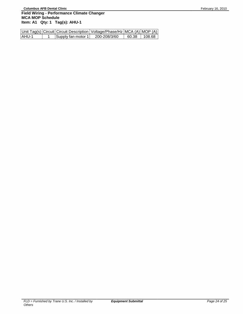
Field Wiring - Performance Climate Changer MCA MOP Schedule Item: A1 Qty: 1 Tag(s): AHU-1
Unit Tag(s) Circuit Circuit Description Voltage/Phase/Hz MCA (A) MOP (A)
AHU-1 1 Supply fan motor 1 200-208/3/60 60.38 108.68

Columbus AFB Dental Clinic February 16, 2010
FLD = Furnished by Trane U.S. Inc. / Installed by Others
Equipment Submittal Page 25 of 25
Field Installed Options - Part/Order Number Summary
This is a report to help you locate field installed options that arrive at the jobsite. This report provides part or order numbers for each field installed option, and references it to a specific product tag. It is NOT intended as a bill of material for the job.
Product Family - Performance Climate Changer
Item Tag(s) Qty Description Model Number
A1 AHU-1 1 Performance Climate Changer ( CSAA ) CSIA017
Field Installed Option Description Part/Ordering Number
Pleated media