Embed Size (px)
Citation preview

https://ntrs.nasa.gov/search.jsp?R=19790015495 2020-03-21T23:50:29+00:00Z

SVHSER 7185
CONCEPT DEFINITION
FOR AN
EXTENDED DURATION ORBITER
ECLSS
PREPARED BY
.HAMILTON STANDARD
UNDER
THE REGENERATIVE LIFE SUPPORT EVALUATION (FUSE) PROGRAM
CONTRACT NAS 9-14782
SEPTEMBER, 1977

SVHSER 7185
TABLE OF CONTENTS
Title Page No.
1 INTRODUCTION
STUDY METHOD
GROUND RULES
RECOMMENDATIONS
TRACE CONTAMINANT CONTROL
OXYGEN SUPPLY Cryogenic Oxygen Storage High Pressure Oxygen Gas Storage Oxygen Storage Comparison Electrolysis
Water Vapor Electrolysis Solid Polymer Electrolyte (SPE) Electrolysis Electrolysis Subsystem Discussion
Oxygen Supply Conclusion
NITROGEN SUPPLY
WASTE MANAGEMENT SUBSYSTEM
WATER MANAGEMENT Fuel Cell Water Stored Water Potable Water Processing
Condensate Processing Subsystem Urine and Waste Water Processing Subsystem
Vapor Compression Distillation (VCD) Air Evaporation Thermoelectrically Integrated Membrane
Evaporator Urine and Wash Water Processing Subsystem
Discussion Water Management Conclusion
CARBON DIOXIDE REMOVAL Lithium Hydroxide Solid Amine - (HS-C)/Relative Humidity Control Solid Amine - (HS-C)/Low Dump Molecular Sieve Dump

TABLE OF CONTENTS (Continued)
Title
Molecular Sieve - Water Save Electrochemical Depolarized Concentrator (EDC)
Dump EDC with Sabatier Reactor EDC with WVE and Sabatier Reactor C02 Removal Subsystem Discussion
TEMPERATURE AND HUMIDITY CONTROL
PRESSURE AND COMPOSITION CONTROL
SYSTEM DISCUSSION
IMPACT OF 10 MEN
VEHICLE CONSIDERATIONS Impact on Existing Shuttle Equipment New Subsystem Locations Spares and Redundancy Comments
Page No.
APPENDIX A
APPENDIX B
iii

SVHSER 7185
Figure No.
1
LIST OF FIGURES
Title ?
Study Method
Cryogenic Oxygen - 3 Kits - 7 Day Mission with 7 Men
Cryogenic Oxygen - 3 Kits - 30 Day Mission, 7 Men
Cryogenic Oxygen - 4 Kits - 30 Day Mission with 7 Men
Cryogenic Oxygen - 4 Kits - 60 Day Mission with 7 Men
Gaseous 02 Storage Weight
Gaseous 02 Storage Volume
Composite Tank for 02 & N2
Gaseous 02 Storage Weight Vs. Cryogenic 02 Storage
Water Vapor Electrolysis
Solid Polymer Electrolysis
Gaseous N2 Storage Volume
Gaseous N2 Storage Weight
Cryogenic N2 Storage Volume
Cryogenic N2 Storage Weight
Waste Management Subsystem for ED0
Cryogenic Oxygen - Quality Available Water Storage Weight (Small Accumu!ators vs. Shuttle Water Tank)
Water Storage Volume (Small Accumulators vs. Shuttle Water Tank)
Page No.
3
24
25
26
27
29
30
31
33
36
40
47
48
49
50
54
58
61
62

LIST OF FIGURES (Continued)
Figure No.
20
21
22
23
2 4
25
SVHSER 7185
Title Page No.
Water Storage Launch Weights 63
Water Storage Volume 64
Water Reclamation Subsystem Schematic 71
Vapor Compression Distillation 75
Air Evaporation 79
Thermoelectrically Integrated Membrane 8 3 Evaporator
Water Storage: Cryogenic Hz + 02 vs. 90 Liquid Hz0 Weight
Water Storage: Cryogenic H2 + 02 vs. 91 Liquid Hz0 Volume
Lithium Hydroxide 96
Solid Amine (HS-C) Relative Humidity 99 Control
Solid Amine (HS-C) - Low Dump 102
Molecular Sieve - Dump 105
Molecular Sieve - Water Save 109
Electrochemical Depolarized Concentrator 113 (EDC) - Dump Sabatier Reactor
EDC/WE with Sabatier Reactor 12 0
C02 Removal Subsystems 123
Subsystem Interactions 12 7
Mimions Evaluated 12 8
Extended Shuttle ECLSS Impact Summary 130 Data Sheet

LIST OF FIGURES (Continued 1
Figure No.
40
41
SVHSER 7185
T i t l e Page N o .
Delta Launch and Delta Reentry Weight 136
C02 P a r t i a l Pressure Versus Elapsed 14 4 T i m e From Addition of 3 Men to Cabin
LIST OF TABLES
Table No. Title
1 Subsystems Examined
2 Contaminants Exceeding SMAC Values During Mission
3 Oxygen Supply Subsystem
4 02 Generation - WVE 5 Oxygen Generation - Solid Polymer
Electrolyte (SPE)
6 Electrolysis Subsystem Dzta Comparison Summary
SVHSER 7185
7 Water Management Subsystem
8 Water Management - VCD 9 Water Management - Air Evaporation 10 Water Management - TIMES 11 Water Reclamation Subsystem Comparison
12 Additional Water Required When
13 C02 Control Concepts
14 C02 Removal - LiOH 15 C02 Removal - Solid Amine (Hs-C) RH
16 C02 Removal - Solid mine (HS-C) - LOW Dump
17 C02 Removal - Molecular Sieve Dump 18 C02 Removal - Molecular Sieve - Water
Save
19 C02 Removal - EDC Dump 20 C02 Removal - EDC With Sabatier Reactor
Page No.
vii

Table No.
21
22
23
24
25
26
27
SVHSER 7185
LIST OF TABLES (Continued)
T i t l e - C02 Removal - EDC/WVE With Sabatier Reactor
Orbiter Missions Studied
Delta Launch Weight Summary Sheet
Delta Re-Entry Weight Summary Sheet
Delta Volume Summary Sheet
Delta Power Summary Sheet
Delta Heat Rejection Summary Sheet
Page N o .
121
viii

SVHSER 7185 ' i
INTRODUCTION
Extending the oeven-day Shuttle Orbiter baseline mission requires
an evaluation of the Environmental Control and Life Support
(ECLS) System in order to determine those changes necessary or
desirable so that the Orbiter payload capability will not be
seriously compromised.
This report defines the ECLSS requirements and subsystem options
for extended duration Orbiter missions. Using ground rules
agreed to by the NASA and reviewed by prime vehicle contractors,
each major ECLS aubsystem was examined, and potential methods of
extending * 2 dssion capability were studied.
The data presented reflects ECLSS actual contractor data as far
as it was possible to obtain. The parametric data prepared by
Hamilton Standard entitled ''Thermal Control and Life Support
Subsystems Parametric Data for Space Station" served as the basis
for much of the data contained herein.
The mission evaluated most extensively for this effort was a 30-
day mission with a crew size of seven men. However, missions up
to 90 days duration with crew sizes of three to ten men were also
examined.
* . - d
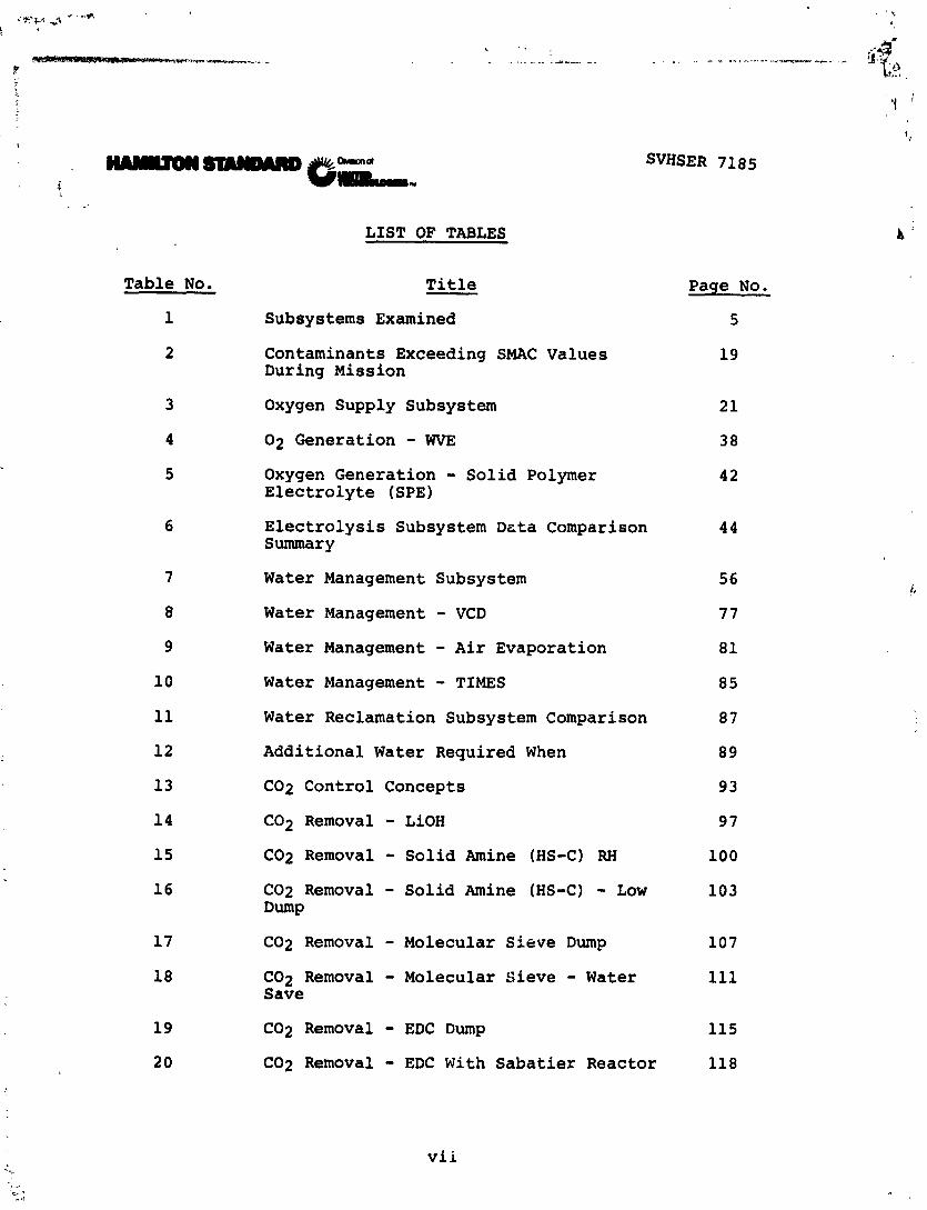
STUDY METHOD
SVHSER 7185
The methodology used in this study is shown in Figure 1. A set
of ground rules were prepared and circulated to NASA/JSC, NASA/
MSFC, Rockwell International, Grumrnan, and McDonnell Douglas.
Comments were received, and the ground rules were revised and
resubmitted for review. The complete version of the ground rules
actually used are noted in the following report section.
Eight Shuttle Orbiter subsystem functions were evaluated. In
some cases, where no other practical subsystem options were
evident, the subsystem required for the extended Orbiter mission
was defined. If a number of viable subsystem concepts for a par-
ticular function were available, each was evaluated and the
optimum concept selected. In the case of the C02 Removal subsys-
tem, the subsystem selection was dependent on many system level
factors, and so the C02 Removal subsystem was examined on a
system basis. These system factors indicated that the C02
Removal subsystem selection was dependent on the ECLS system
water balance and whether the fuel cells were merely idled or
scheduled to produce the water required. Other factors that had
to be considered were whether the additional water was stored on
board or reclaimed from waste water, The number of hours of
extra vehicle activity (EVA) was also an influencing factor.

FIGURE 1 - STUDY METHOD
3
SVHSER 7185

SVHSER 7185
Various missions were defined based on data obtain from other
Shuttle, Space Station, and power module studies. The impact of
these missions on each system was evaluated, and the significant
impacts on payload launch and landing weiy'lt, power, volume, heat
rejection, and cost were determined relative to the baseline
Shuttle seven-day mission. A final C02 Removal subsystem selec-
tion was postponed at this time pending establishment of acceptable
trade criteria.
The trade criteria must establish the relative importance of
weight, power, volume, heat rejection, cost, and the impact of
significant qualitative considerations. Once the trade criteria
is established, an optimum C02 subsystem selection considering
all of the missions defined can be determined using the data
compiled in this study. The complete ECLS system for at extended
Orbiter can than be defined.
Table 1 defines the subsystems examined and the level at which
they were studied and evaluated.

SUB
SYST
EMS
EXA
MIN
ED
Tra
ce C
on
tam
inan
t C
on
tro
l
Oxy
gen
Su
pp
ly
Nit
rog
en
Su
pp
ly
Was
te M
an
ag
em
en
t
C0
2 R
emo
val
Wat
er S
up
ply
W
ater
Rec
lam
atio
n
Tem
per
atu
re a
nd
Hu
mid
ity C
on
tro
l
Pre
ssu
re a
nd
Co
mp
osi
tio
n
Su
bsy
stem
S
yste
m
Lev
el
Lev
el
4
-
4
4
4
-
4
-
4
d

- GROUND RULES
SVHSER 7185
The ground rules used for this study are shown on the following
pages.

SVHSER 7185
1. Design critical functions to meet fail safe criteria. Fail
safe is defined as suitable backup systems or redundancy to
provide 20 hours of ECLSS contingency time. A total of 96
hours vehicle contingency time is required for all subsystems.
This criteria will provide a reliability equivalent to the
present Shuttle ECLS system seven-day design.
2. For in-flight maintenance it is permissible to replace
expendable items, life limited items, and failed items
providing the item to be maintained is accessible, results
in reduced system penalties, and the down time does not
impact system performance significantly.
3. As a goal, all equipment, w:th the possible except'on of
expendables, will be installed in the Shuttle Orbiter.
4. It will be considered permissible to discharge overboard
carbon dioxide, vapors, and trace contaminants during normal
operation. However, the ECLS system shall be capable of
operation under a "no dump" situation for a period of 24
hours.
5. Interface will be with the existing Shuttle Orbiter.
SVHSER 7185
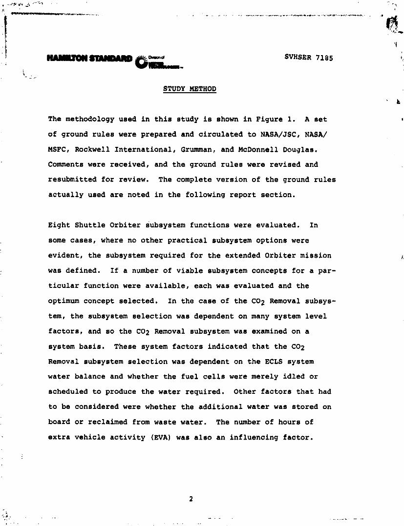
6. Baseline crew size design point is seven men. Crew size
range is four to ten men. With 10 men or mission durations
beyond 30 days, an additional habitability volume of 500 ft3
minimum will be made available.
7. Baseline nominal mission duration design point is 30 days.
Mission duration can then be extended to 60 and 90 days.
8. C02 partial pressure will be maintained below 7.6 mmHg.
Daily average will be maintained at 5.0 mmHg.
9. Local readouts and warnings will be utilized as it is
assumed that Orbiter computer system has no additional
capacity.
10. No orientation restrictions will be imposed by the ECLS
system other than that required for on-orbit heat rejection.
11. Total cost impact is primary consideration. Reentry penal-
ties will be considered more significant than launch penalties.
12. All subsystems considered shall be capable of certification
for actual flight use by early 1983.

SVHSER 7185
. ,
13. All ECLS subsystems will be designed for an oxygednitrogen 1
:nixture of 14.7 psi and have the capability of operation at
8 psi without damage.
14, The ECLS system provides or controls:
- Oxygen
- Nitrogen
- Potable Water
- Wash Water (Hand Wash, No Shower)
- Temperature and Humidity Control
- Carbon Dioxide
- Trace Contaminants
- Waste Collection and/or Disposal
- Heat Rejection
15. The ECLS system shall be capable of operation with water
supplied from the fuel cells operating normally or with the
rater produced by a fuel cell supplied with gas equivalent
to an idll fuel cell condition with no useful power output.
16. Pifload experiments or missions requiring such things as no
vehicle dumps, specific vehicle orientations, etc. will be
cl~arged agzinst that particular mission or experiment and
will not be considered as a penalty against the Shuttle
9 r biter ECLS system.
SVHSER 7185
17. The following data will be used in defining the enhanced
Shuttle ECLS system. Metabolic data is based on a 70°F
cabin and a level of 10,733 Btu/man-day as currently defined
for the Shuttle Orbiter.

WH2O Sweat
@ 65O 2.72 lb/man day 70' 3.49 lb/manday 75O 4.19 lb/man day
WH7O Feces = 0.20 lb man day
Urine
Water = 3.31 lb/man day Solids = .13 lb/man day
Water For Food
Water in Food = 0.57 lb/man day For Food Prep. = 1.96 lb/man day Drink = 3.74 lb/man day Food Prep. and Drink = 5.70 lb/man day
Solids in Food = 1.30 lb/man day
SVHSER 7185
Solids in Feces = .07 lb/man day
Wash H20
Hand/Body Wash = 2.55 lb/man day
Fuel Cell Power
Total On Orbit = 21 KW Available for Orbiter = 10-14 KW Available for Experiments = 8.0 KW Max.
(4.7 KW Avg.)
Lbs/Day For No. Men
4 7 10
8.4 14.77 21.1
7.04 12.32 17.6

SVHSER 7185
L ! Conversion to AC Efficiency = 76%
Solar Cell Power - LEO Total On-Orbit 25 KW Reg. DC-28 V 560 lbs/KW Reg. AC-400 Hz 120/208 V 650 lbs/KW
lieat ~ejection/Sortie Ops
a) Fuel Cell with 8 Panel Rad 110,000 Btu/hr (21 KW) b) Solar Cells - 8 Panel Rad-89,000 ~tu/hr (25 KW)
Orbiter Leakage
Cabin Waste Management Air Lock Tunnel Adapter
6 lb/'day .25 lb/man day 1 lb/day 1 lb/day

SVHSER 7185
RECOMMENDATIONS
As a result of the study effort described herein, the following
recommendations are made and summarized below:
Subsystem Recommendation
Trace Contaminant Install expendable adsorption canisters
Control periodically in LiOH canisters to pro-
vide adequate trace contaminant control
up to a period of 90 days.
Oxygen Supply
Nitrogen Supply
Utilize existing fuel cell cryogenic oxygen
supply up to 60 days. Beyond 60 days,
must improve insulation.
Use existing high pressure nitrogen
tanks until nitrogen requirement
approaches 600 pounds (over 60 days).
At this point, use improved cryogenic
oxygen storage tank with improved
insulation.

Subsystem
W a ~ t e Management
C02 Removal
Water Supply
SVHSER 7185
Recommendation
Use existing Shuttle Orbiter subsystem
with the addition of a biocide storage
tank to replenish the biocide in the
waste storage tanks for extended missions.
For missions exceeding a total of 210
man-days, an additional commode will be
required for each additional 210 man-day
period.
Use a regenerable C02 Removal subsystem
for all missions. (Specific concept to
be determined. )
Use all fuel cell water available. For
additional water, schedule fuel csll
operation to make up water deficiency if
possible or supplement with stored water
for missions up to 60 days. Beyond this
period, incorporate the Thermoelectrically
Integrated Memembrane Evaporator Subsystem
(TIMES) Water Reclamation Subsystem.

Subsystem
Cabin Temperature
and Humidity Control
Thermal Control
Pressure and
Composition
SVHSER 7185
Recommendation
Use existing Shuttle Orbiter subsystem.
Use existing Shuttle Orbiter subsystems.
Investigate the possibility of using
waste water as a heat sink.
Use existing Shuttle Orbiter subsystem.
SVHSER 7185
,.. TRACE CONTAMINANT CONTROL
The Trace Contaminant Control Subsystem removes atmospheric trace
gases from the cabin air to maintain their concentrations at
acceptably low levels. As mission length increases, the quantity
of trace contaminants will gradually accumulate and will reach
unacceptable levels if not controlled.
The subsystem defined below which is capable of controlling trace
contaminants to an acceptable level consists of a removable
sorbent bed and a small fan assembly which can be located in a
convenient place in the Orbiter. If the LiOH cartridges are not
used because an alternate C02 Removal subsystem is on board, then
a trace contaminant sorbent bed described below can be resized
fit into the LiOH canister(s).
The analysis for sizing the bed was based upon data contained in
Reference 1 which is a computer model of the Shuttle Orbiter/
Spacelab contaminant control subsystem. The computer model is
based upon contaminant generation rates from equipment installed
in the Spacelab and includes metabolic generation rates. For a
30-day mission a single "adc-on" canister containing activated
carbon and CO oxidation catalyst (2% platinum on charcoal) is
recommended. The bed was designed to be changed out every 15
days.
SVHSER 7185
While the computer program was designed to include contaminant
removal by leakage, the condensing heat exchanger (for soluble
contaminants), the LiOH canisters, and an add-on charcoal bed,
the resultant computer design assumed removal in the condensing
heat exchanger and the add-on charcoal bed only.
It was decided to utilize a 15-day changeout bed to reduce main-
tenance time and number of expendables required. The bed size
determined by the computer model was resized by increasing the
carbon mass and maintaining the same volumetric flow rate and
utilizing the Skylab contaminant bed L/D ratio. In addition,
since the bed size model considered only contaminants which will
reach their SMAC values in 30 days, it was felt desirable to
review the requirements for longer mission periods. For missions
exceeding 30 days, five additionai contaminants shown in Table 2
require control and additional activated carbon must be provided.
From contaminant generation rates and including a coexistence
factor to account for coadsorption, the saturated zone additicn
required was determined to be 0.5 pounds. As a result, bed was
resized to control the additional contaminants.
The result is a canister containing 16.7 pounds of material,
composed of 16.5 pounds of activated carbon (5.6 pounds of which
is H3P04 treated), and 0.2 pounds of CO oxidation catalyst (2%
platinum on charcoal). The canister pressure drop will be on the

SVHSER 7185
order of 1.0" w.g. with a fan power of 1.3 watts at a flow rate
of 4.0 CFM. Bed dimensions are 9.9" O.D. x 12.1" lona. This
bed, changed out every i5 days, will adequately control all trace
contaminants for mission durations of up to 90 days duration.
If a regenerable C02 Removal Subsystem is used in place of the
present LiOH rartridges, the above chemisorbent bed may be
resized to be located in the Shuttle Orbiter LiOH cr isters.
In view of the fact that Apollo, Gemini, the 90-day Manned Test,
and Naval submarines do not require airborne bacteria control, it
is recommended that none be included for extended Shuttle. If it
is later found that bacteria filters are required, a filter and
fan can be added.
Reference
1. Development of a Computer Program for Spacelab Contaminant
Control Analysis, LMSC, January, 1977.


OXYGEN SUPPLY
Oxygen in the Extended Duration Orbiter (EDO) is used to power
the fuel cells, to supply metabolic oxygen for cabin leakage
makeup, and as an emergency backup supply. The quantity of
oxygen required for the baseline seven-man, 30-day mission with
the fuel cells in the idle mode is shown in Table 3. As noted in
the table, a minimum of two Shuttle oxygen cryogenic tanks are
required to meet the minimum 30-day oxygen requirement. Fuel
cell idle mode is the lowest fuel cell operation level which can
be maintained without shutting the cells down. For the three
fuel cells on board the Shuttle a total of 1 kw is consumed for
this operation resulting in the production of 654 pounds of water
over a 30 day period. The oxygen required slightly exceeds the
boil-off rate of the cryogenic storage tanks; and boil-off is,
therefore, not a penalty factor.
Additional oxygen is required for launch reentry and emergency,
adequate fuel cell power generation, EVA purposes, or to operate
an Electrochemical Depolarized Concentration (EDC) if used.
The oxygen requirements for a mission can be met by:
- Additional Cryogenic Kits or Independent Cryogenic
Oxygen Tanks

SVHSER 7185
TABLE 3 - OXYGEN SUPPLY SUBSYSTEM

- High Pressure Gas Storage Tanks
SVHSER 7185
- E l e c t r o l y s i s o f W a t e r
The above subsystems are described in further d e t a i l i n the
following report sec t ions .

CRYOGENIC OXYGEN STORAGE
SVHSER 7185
Cryogenic oxygen is the method used for storing oxygen on board
the present Shuttle Orbiter. The present subsystem is capable of
supplying oxygen with an acceptable ?-jil-off rate for a period of
slightly over 60 days. Each tank stores 781 pounds of cxygen ar:'
weighs 1,.113 pounds, including mounting structure. Yhe Orbiter
oxygen is normally stored on board in a kit which includes 92
pounds of cryogenic hydrogen. Since this subsystem has a light
weight and small volume and has been designed and certified for
use in the Shuttle, it has a low cost, and as a result, is the
optimum method for storing additional quantities of oxygen
required for Extended Duraticn Orbiter missions.
The quantity of oxygen available for various cyrogenic kit in-
stallations are shown in the figures noted below. The minimal
disposition requirements and quantity left over are also sv,own.
Mission Primary Number Fuel Cell Length power- of Kits Operation Figure
7 Fuel Cell 3-4 Normal -2
30 Solar Cell 3 Idle -3
30 Solar Cell 4 Idle - 4 60 Solar Cell 4 Idle -5

SVHSER 7185
FIGURE 2
CRmGENIC OXYGEN-3 KITS-7 DAY MISSION WITH 7 MEN

SVHSER 7185
FIGURE 3
CRYOGENIC OXYGEN-3 KITS-30 DAY MISSION, 7 MEN

SVHSER 7185
,
F I G U R E 4
CRYOGENIC OXYGEN-4 KITS-30 DAY M I S S I O N WITH 7 MEN

739.2 LBS METABOLIC
02
FIGURE 5
CRYOGENIC OXYGEN-4 KITS-60 DAY MISSION WITH 7 MEN
SVHSER 7185

HIGH PRESSURE OXYGEN GAS STORAGE
SVHSER 7185
Currently on board the Shuttle, 65 pounds of oxygen at 3,300 psi
is stored for emergency use. Total tank weight, including
packaging, is 195 pounds.
As the need for oxygen increases for longer missions, the possi-
bility of adding additional high pressure storage tanks versus a
single optimum tank was investigated.
The weight and volume associated with using multiple tanks of the
existing Shuttle size versus a single optimum tank is shown in
Figures 6 and 7. Figure 8 defines the tank assumptions used.

SVHSER 7185
Operating Pressure = 3300 p s i a
500 1000
USABLE 0 2 WEIGHT (POUNDS)
Figure G Gaseous 02 Storage Weight

SVHSER 7185
1000 2000
USABLE 02 WEIGHT (POUNDS)
F igure 7 Gzseous 02 Storage Volume

SVHSER 7185
a ~ e v l a r 49 wound f i bers over C AL-4V T i tanium f o r 112 (and over inconel 718 f o r 02) load sharing 1 i n e r and bosses
a Burst f a c t o r = 1.5 Proof f a c t o r = 1.25
0 Packaging f a c t o r = .35 x To ta l weight ( F u l l o f gas) Large tanks
2000 3300
OPERATING PRESSURE
Figure 8 Composite Tank for 02 & N2 -.

SVHSCR 7185
OXYGEN STORAGE COMPARISON
The total weight of storing gas cryogenically veisus that of
storing gas at high pressure was compared and plotted cn Figure
9. 9s can be noted, utilization of the existing cryogenic
storage tank is much lighter than storing high pressure gas even
in a single tank. As a result of this and the fact that the
cryogenic tankage already exists for the Shuttle, it is concluded
that there is no change to the Orbiter oxygen storage system
required for extended missions up to 6C days as long as oxvgen is
required continuously. Beyond this point the cryogenic tankage
insulation must be improved to reduce boil-off as noted previnusly.

Figure 9
1000 2000
USABLE 02 WEIGHT (POUNDS)
Gaseous 02 Storage Weight Vs. Cryogenic 02 Storage
3 3
. - . -- -- - - . . -- - . . . . + .-

Rmmd
mm
ELECTROLYSIS
SVHSER 7185
Another method of producing oxygen is by electrolysis of water.
Two subsystems for generating oxygen using electrolysis of water
were considered for use in the Extended Duration Orbiter. These
are :
- Water Vapor Electrolysis ( W E )
- Solid Polymer Electrolysis (SPE)
Both of these subsystems are discussed in the following paragraphs.

SVHSER 7185
Water Vapor Electrolysis
The Water Vapor Electrolysis Subsystem (WVE) combines oxygen
generation with partial cabin humidity control. The W E concept
is unique in that water is fed as vapor directly from the cabin
atmosphere into the WVE module for conversion to hydrogen and
oxygen. The subsystem is schematically shown in Figure 10.
Cabin air is drawn into the WVE module and through the module
cells by the subsystem fan. Water vapor is absorbed and elec-
trolyzed in the cells, and the product oxygen is returned directly
to the air stream through the subsystem fan and back irtz the
cabin. The generated hydrogen is delivered to the C02 Reduction
Subsystem. The process flow also cools the WVE module with cabin
air. A subsystem controller regulates current flow into the W E
module to provide 02 partial pressure control. The WVE consumes
62.5% of the latent vapor level in a cabin. Water vapor consump-
tion rate and the hydrogen production rate are a function of the
oxygen produced.
Prior to shutdown or maintenance of the subsystem, a supply of
nitrogen is required to purge hydrogen from the subsystem.

SVHSER 7185
FROM 3ABIN TEMPERATURE
AND HUMIDITY CONTROL HEAT EXCHANGER
T I
T I
N2 PURGE - vm W E
ONTROLLE El
FIGURE 10
WATER VAPOR ELECTROLYSIS ( W E )
I TO VENTILATION
DUCT

SVHSER 7185
All heat generated by the subsystem was assumed to be dissipated
as heat to the cabin. This subsystem has no expendable items.
Table 4 defines the subsystem characteristics for the extended
Orbiter baseline condition.


SVHSER 7185
Solid Polymer Electrolyte (SPE) Electrolysis
The Solid Polymer Electrolyte Subsystem consists of a water-fed
multi-cell electrolysis module and functional components. A
schematic of the subsystein is shown on Figure 11.
Process water is pumped into the unit through a deionizer to the
electrolysis module cells at a controlled maximum temperature of
150°F. The water temperature is maintained by a temperature
regulating valve and a regenerative heat exchanger. Some of the
process water is dissociated into hydrogen and oxygen by elec-
trolysis. The excess water absorbs the module waste heat and is
discharged with the produced hydrogen. Oxygen is delivered to
the cabin directly from the electrolysis cell through redundant
pressure regulators. These oxygen backpressxe regulators
control the oxygen absolute pressure higher than the hydrogen
absolute pressure. This assures a positive pressure differential
of oxygen greater than the two-phase mixture in the module such
that no water is hydraulically transported to the oxygen side of
the module and eliminates entrained water in the oxygen discharge.
Hydrogen is vented from a phase separator-pump through a differ-
ential pressure regulator and is further regulated at an absolute
pressure by a hydrogen backpressure regulator where it is dis-
charged to the C02 Removal and C02 Reduction Subsystems, as
required.

SVHSER 7185

SVHSER 7185
Power is delivered to the electrolysis module through a power
conditioner in the subsystem controller which acts as a current
regulator for maintaining a selected gas (02) production rate.
The power conditioner which operates at about 92% efficiency
rejects waste heat to a cold plate through which process water,
being delivered to the hydrogen side of the electrolysis module,
is circulated. All power supplied to the controller, phase
separator, and makeup pump were assumed to be dissipated as heat
to the cabin. Heat rejection by the power conditioner has
already been discussed. The heat rejection of a makeup pump has
been included; however, it will operate only about 10% of the
time .
Prior to shutdown or maintenance of the subsystem, a supply of
nitrogen is required to purge hydrogen from the subsystem.
The subsystem requires replacement between missions of a water
inlet filter and an deionizer. Table 5 defines the subsystem
characteristics for the extended Orbiter base condition.

SVHSER 7185
CONCEPT : - Solid Polymer Electrolyte (SPE) - - ----

Electrolysis Subsystem Discussion
SVHSER 7185
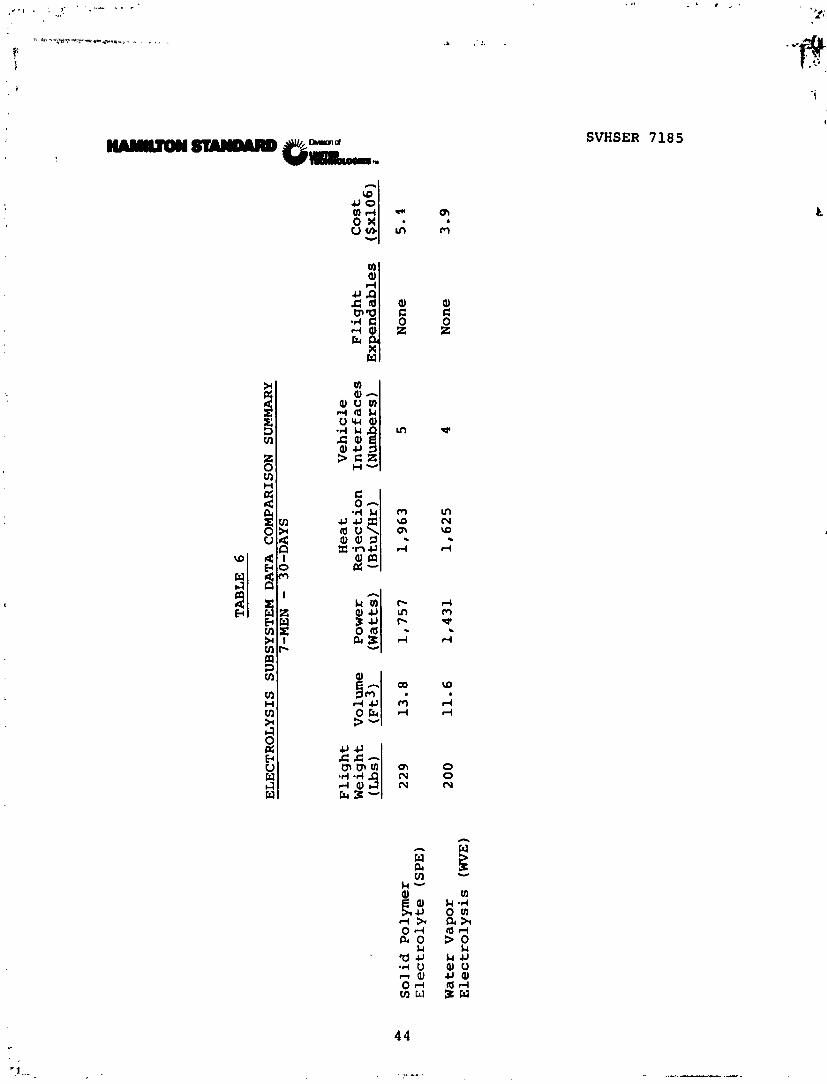
The characteristics of the above two electrolysis subsystems were
summarized as noted in Table 6. An examination of this table
shows that the WVE subsystem has the best overall characteristics
of the two for use in the Extended Duration Shuttle Orbiter. It
imposes the least penalty on the vehicle. As a result, the WVE
Subsystem characteristics were used in subsequent ECLS system
evaluations involving the use of electrolysis for oxygen and
hydrogen generation.
4
f I P
Solid Polymer
! Electrolyte (SPE)
Water Vapor
Electrolysis (WVE)
TABLE 6
ELECTROLYSIS SUBSYSTEM DATA COMPARISON SUMMARY
7-MEN -
30-DAYS
Flight
Heat
Vehicle
Weight
Volume
Power
Rejection
Interfaces
Flight
Cost
(Lbs)
(~t3) (Watts) (Btu/Hr)
(Numbers)
Expendables
(Sx106)
229
13.8
1,757
1,963
5
None
5.1
200
11.6
1,431
1,625
4
None
3.9

OXYGEN SUPPLY CONCLUSION
SVHSER 7185
A review of the three methods of providing oxygen for the extended
Orbiter mission shows that cryogenic storage of oxygen is the
optimum method. It has the lowest weight, lowest cost (already
developed), and least impact on the vehicle. For mission periods
beyond 60 days, the cryoqenic takage insulation must be improved
to extend its mission capability.
The use of electrolysis for oxygen generation is not competitive
on a subsystem basis due to the high power and heat rejection
involved. It appears that as long as a fuel cell is the princi-
pal power supply, electrolysis will never trade off. However, if
a power module is used, electrolysis might be considered, Tne
possibility of integration with other subsystems on a total
system basis was examined in the System Section of this report
using the Water Vapor Electrolysis Subsystem concept.

NITROGEN SUPPLY
Nitrogen gas is used in the cabin for cdbin atmospheric leakage
makeup and for miscellaneous uses. For the baseline mission, 315
pounds of nitrogen is required. Nitrogen is currently store? in
the Shuttle Orbiter in four high pressure (3,300 psi) tanks, with
each containing 63 pounds of gas. As a result, two additional
tanks will be required for the 30-day mission.
Nitrogen gas can be stored in high pressure tanks ( 3 , 3 ' : 2sia) or
cqogenically. Figures 12 and 13 show the weight volume
respectively of storing gas using the existinq ,xttle tank and
in storing gas in a single new nitrogen tan:. Figures 14 and 15
show the weight and volume respectively of storing gas cryogenic-
ally uoing the existing Orbiter cryogenic oxygen tank or :~ new
single cryogenic nitrogen tank. With t.he present oxygen cryogenic
tank the boil-off rate, when charged with nitrogen, is about two
times the usage rate so that much more nitrogen mu.st be stored
cryogenically. For mission periods approaching 60 days (which
will require up to 630 pounds of nitrogen), it appars advisable
to stay with the existing high pressure nitrogen tanks. The
volume of a single larger tank of :his capacity might be im-
practical to install in the vehicle and would require large
nonrecurring costs.

SVNSER 7185
200 400 600 800
USABLE N2 WEIGHT (POUNDS)
F igure 12 Gareous N2 Storage Volume

0 200 400 60 0 80 0
USABLE N2 WEIGHT (POUNDS)*
F igure 13 G a s a m N2 Storage Weight

SVHSER 7185
20 0 400 600 80 0
USABLE N2 WEIGHT (POUNDS)*
Figure 14 Cryogenic N2 Storage Volume

SVHSER 7185

SVHSER 7185
Beyond 60 days it would be advisable to use the improved insulated
cryogenic oxygen tank to reduce the overall weight and volume
penalty, as it is assumed the reduced boil-off rate would be
close to the nitrogen requirements. At this mission length, the
nitrogen requirements (630 pounds) would approach the capacity of
a single oxygen cryogenic tank (781 pounds) and would be much
lighter than multiple small high pressure tanks. A new cryogenic
tank would be lighter as shown in Figure 14, but again the non-
recurring cost would be high and appears unwarranted unless many
long duration missions exceeding 60 days are planned.

WASTE MANAGEMENT SUBSYSTEM
SVHSER 7185
The Orbiter Waste Management Subsystem coilects and stores
condensate, urine, and wash water in two waste water storage
tanks which contain a predetermined quantity of biocide. The
tanks are sized to hold a total of 320 pounds of waste water.
The subsystem also contains a heated overboard dump nozzle to
permit dumping of the waste water. The subsystem also collects
feces and tissue wipes in a vacuum dry slinger type commode. The
commode is sized to hold 210 man-days of feces and wipes.
The Waste Management Subsystem recommended for use in the Ex-
tended Duration Shuttle Orbiter is identical to that currently
used on board the Shuttle (Flight 6 and subsequent). The only
change is the addition of a biocide tank and associated valving
so that the biocide in the waste tank can be replenished after
the contents are discharged overboard or processed for reclamation.
A schematic of the recommended system is shown in Figure 16.
As the present commode is sized for a 21C man-days of operation
and each waste water tank holds 160 pounds of waste water, dumping
of liquids approximately every four to seven days (depending on
the quantity of relative humidity condensate collected) will be
required. If a waste water reclamation subsystem is utilized,
dumping of waste water will not be required, except in the event

SVHSER 7185
of a failure of the waste water reclamation subsystem or to
reduce the vehicle landing weight. To extend the mission range
beyond 210 man-days, an additional commode must be carried for
each 210 man-day increment.

WAS
TE M
AN
AG
EMEN
T SU
BSY
STEM
FO
R E
D0
Uri
nal
L
Was
h
- Wat
er
- W
ater
Sp
ace
Vac
uu
m
Bio
cid
e T
ank
AR
S
Wat
er
Co
nd
ensa
te
To
W
aste
W
ater
n
M
- - Dum
p
Tan
k T
ank
Dra
in

WATER MANAGEMENT
SVHSER 7185
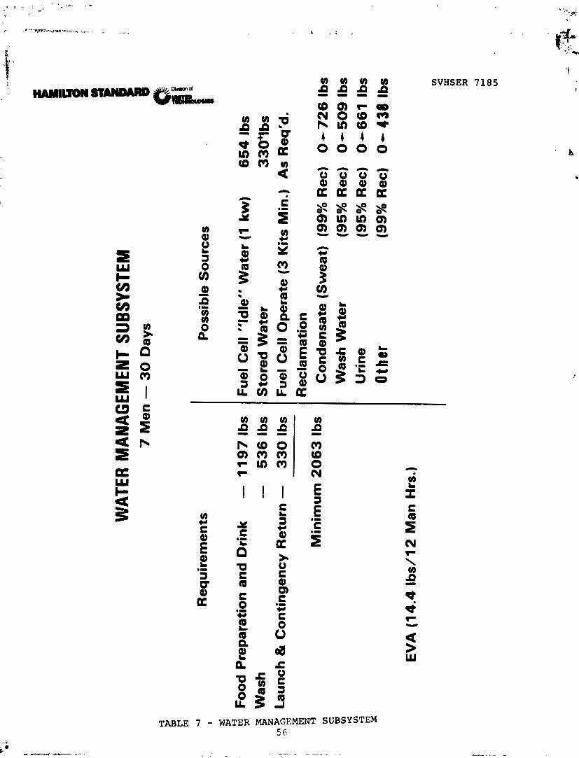
Water is required on the extended Shuttle Orbiter for four prin-
cipal purposes: food preparation, drink, washing, launch and for
contingency return, and in the flash evaporator for supplemental
heat rejection.
In this discussion and according to the ground rules, the use of
water for an orbit heat rejection was not considered. As a
result, a minimum of 2,063 pounds of water is required to com-
plete the Extended Duration Shuttle Orbiter 30-day mission as
shown in Table 7. This water can be provided by fuel cell water,
stored water, or reclaimed water. Each of these water sources
are discussed in the following paragraphs.
V ) V ) V ) V ) P P P P --.I-
SVHSER 7185
TABLE 7 - WATER MANAGEMENT SUBSYSTEM 5 6

SVHSER 7185
FUEL CELL WATER
Water is a product of the fuel cells as power is generated.
During solar cell operation, the fuel cells are never completely
shutdown, some water is always available from the fuel cell. The
minimum power generation (defined as the "idle" mode) for all
three fuel cells is 1 kw. This power is used to keep the cells
warm and ready for instant power up condition. For the 30-day
mission, 654 pounds of water is produced. Any additional fuel
cell operation will directly increase the quantity of water
produced.
Figure 17 defines the quantity of oxygen available when the three
baseline cryogenic kits are launched full. It shows that there
is available 1,114 pounds of oxygen which if used to generate
power will produce all the water required for a 30-day mission;
115.9 pounds of oxygen is left over. To produce this water the
average fuel cell power output would be 2.6 kw, which may not be
useful power. This water can be produced continuously or peri-
odically depending on the power requirement. Operation of the
fuel cell to produce the water required at a rate within the
existing water storage capacity is defined as "scheduled" fuel
cell operation. As the number of cryogenic kits is increased for
more fuel cell power generation, the easier the scheduling of the
fuel cell operation becomes as more water is available.

. . CR
YOG
ENIC
OXY
( Y - Q
UA
NTI
TY A
VAIL
ABLE
;.*
4
'-- .,
E 1;
>
Bas
elin
e - 3
Kit
s
eaka
ge
(64.2
Lbs
.) ?)
'i
LE i:
CF B'
Bal
ance
d W
ate
r O
pera
tio
n
(958.1
Lbs
. =
1078.5
Lbs
. H
20
) T
ota
l O
utp
ut
of
2.6
kw
7 M
en
- 3
0 D
ays
,,11"... 1,.- .... r.1. '- a . *- I., -- ,.-- - , , ,. , , , , , ,,,, , ,,,_,l_, , .,__ lll.,,,-IIII.IIIII-L~ ,--".-h.#.. ..A- . . .. ....-,".-.. ,' I-., ,---.-P"
..rra.p.,.,.-Fr ".-, *.*, - -,,, ,,., .-.,. -...,..- l. ..n..CI . , I . .. -.-..m.-.. -' - , .,. , - ,, , . . - ..- , ?,. A'--' -*'sr*--.
,,, , - - , , ,,\"+ ''*y!?PmF 7.;
In summary, all the water requirements (not including on Orbit
heat rejection which is not required according t? the ground
rules) for the extended Orbiter operation can be met with a
minimum of three cryogenic kits and with scheduled fuel cell
operations. If this cannot be accomplished, then additional
water (stored or reclaimed) will be required.

SVHSER 7185
STORED WATER
Water requirements for the Extended Duration Orbiter can be met
by carrying the additional water required in tanks. The quantity
of water required is dependent on the mission length, crrw size,
C02 removal subsystem, fuel cell operation, whether waste water
is reclaimed, etc. As a result, the data presented in this
section is discussed in terms of usable water weight.
In order to keep costs to a minimum, only tanks with metal tpllows
currently available in the Shcttle Grbiter were used for water
storage. This results in three candidate designs: the Orbiter
potable water tank, the Spacelab water pump package accumulator,
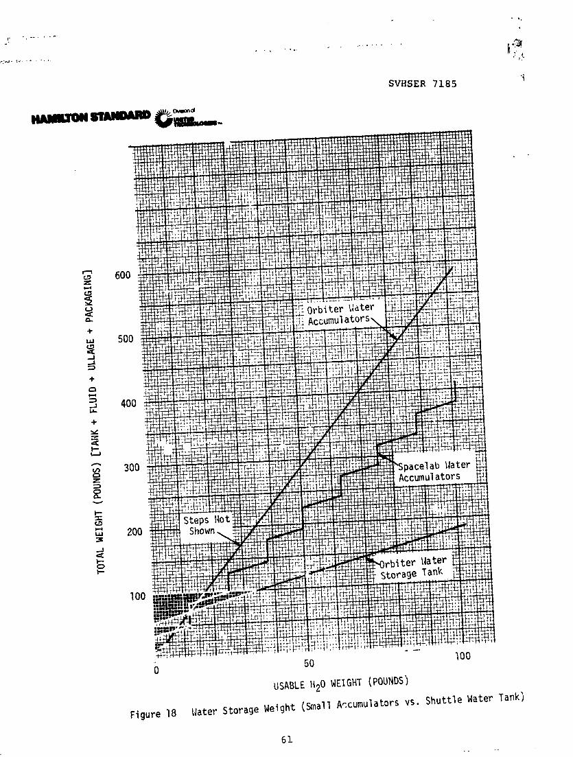
and the Orbiter water pump package accumulator. Figures 18 and
19 show the rzlative weights aud volumes of these designs.
Figure 18 shows that for usable quantities greater than 11 pounds
of water the Orbiter potable water storage tank is the lightest,
and Figure 19 shows that its volume is the least cf the three for
quantities greater than 39 pounds of water. As a result, the 165
pound capacity Orbiter potable water storage tank was used as the
standard storage tank.
Figures 20 and 21 show the total wet tank weight and volume of
the Orbiter potable water storage tank, including a vehicle
packaging factor, which is equal to that of thc present Orbiter
SVHSER 7185

SVHSER 7185
50
USABLE Hz0 WEIGHT (POUNDS)
Figure 19 Water Storage Volume (Small Accumulators vs. Shu t t l e Water Tank) 62

SVHSER 7185
500 1000 1 500
USABLE ti20 WE1 GHT (POUNDS)
F igure 20 Water Storage Launch Weights

SVHSER 7185
500 1000 1500
H20 WEIGHT (POUNDS)
Figure 21 Water Storage Volume

SVHSER 7185
water tank factor. All of the subsequent system trades were
based on using this existing 165 pound capacity Orbiter metal
bellows water storage tank.
Figure 20 also shows that a special new metal bellows tank de-
signed to hold 400 pounds of usable water would be about 110
pounds lighter than using three of the standard Orbiter tanks.
They also show that 1,000 pounds of water in a single large tank
would save 350 pounds. Thus, if a significant amount of stored
water is required, it may prove to be economically wiser to
design, develop, and qualify a new, larger metal bellows tank
design than to pay for many smaller Orbiter tanks, which would
also weigh more. This assumes that the resultant volume of a
single tank would be acceptable. Figure 21 shows the relative
volume of each approach.
If a new tank design is considered, the possibility of using a
bladder rather than a stainless steel bellows was investigated.
To hold 1,000 pounds of usable stored water, a single bladder
tank subsystem would weigh about 50 pounds less than the single
metal bellows design; but it is considered a less reliable design
which would be life limited and have potential gas permeability
problems.

SVHSER 7185
POTABLE WATER PROCESSING
Another method of supplying additional water for use in the
Extended Duration Orbiter is to reclaim waste water. Three types
of waste water are generated during the mission; condensate,
urine, and wash water. Condensate can be processed using a
relatively simple multifiltration system. A distillation unit is
required to reclaim urine. Wash water can be reclaimed using
multifiltration, hyperfiltration, reverse osmosis, or distilla-
tion. Regardless of the water being processed, the water quality
must meet the Shuttle potability requirements. Iodine at a con-
centration of 5 ppm is added to the water for bacteria control,
and the water quality is checked with a Water Quality Monitor
Subsystem (WQMS). Since the current WQMS utilizes a relatively
large quantity of expendables and power, three possible 30-day
operating modes were examined to determine optimum operation.
These were: continuous monitoring, 50% monitoring, and 5%
monitoring.
For the continuous monitoring use, the unit uses about 170 watts,
and the expendable chemicals are at a maximum which results in a
total launch weight of about 82 pounds.
For the 50% duty cycle case a Spacelab water pump package accum-
ulator was incorporated which can store 6.5 hours of processed
water. ,-She WQMS must go through a warm-up and calibration cycle

SVHSER 7185
each time it is turned on before an accurate reading can be
attained, and it must perform a flush cycle before it can be shut
off again. This takes about four hours per total on-reading-off
cycle. Thus, the unit actually operates four out of every 6.5
hours. If the reading is good, the accumulator is then emptied
to the potable water storage tank, and a cycle is restarted.
This type of intermittent WQM actually operates about 62% of the
time, uses an average power of about 105 watts, and weighs
(including tankage) about 107.7 pounds. Thus, this intermittent
unit is about 25.7 pounds heavier but has an average power
savings of 65 watts when compared to a continuous WQMS.
If thz Orbiter tank (165 pound capacity) is used as the accumula-
tor, the WQMS need only be operated once every three days or 40
hours in a 30-day mission. This yields a 5.5% duty cycle and an
average power of 9.4 watts and weighs 111 pounds (including
tankage). The 5.5% duty cycle operation of this subsystem saves
on an average basis 160.6 watts and only weighs 2.9 pounds more
than the 100% duty cycle WQMS. In addition, it saves 95.6 watts
and only weighs 3.3 pounds more than the 62% duty cycle version.
As a result, the 5.5% duty cycle was selected for use in all
subsequent subsystem trade studies.

SVHSER 7185
. A;.
Condensate Processing Subsystem
The Potable Water Processing Subsystem for reclaiming condensate
water for the Extended Duration Orbiter consists of a multifil-
tration unit, a Water Quality Monitor Subsystem (WQMS) , an iodine dispenser, and a process water storage holding tank.
The subsystem receives water from the Atmospheric Revitalization
Subsystem (ARS) water separator, processes it through the multi-
filtration unit, sterilizes it with 5 ppm of iodine, checks the
water quality, and stores water until it can be discharged to the
existing Shuttle water supply tanks. If the water quality is not
acceptable, the water is returned to the Shuttle Waste Management
Subsystem. It has been assumed that the process water quality,
which is acceptable for drinking, will be acceptable for use in
the Shuttle flash evaporator.
A subsystem was sized to process all the condensate generated
during each mission considered. The actual condensate quantity
processed is dependent on the C02 Removal subsystem and number of
EVA'S which determines the quantity of condensate (if any) re-
moved in the cabin temperature and humidity control condensing
heat exdhanger .

SVHSER 7185
A process efficiency of greater than 99% was assumed in sizing
the multifiltration units. It contains a carbon bed and an ion
exchange bed. The subsystem bed was sized to last for a minimum
of 30 days. Expendables will be replaced on the ground during
vehicle turnaround. For missions beyond 30 days the bed will be
replaced every 30 days using in-line disconnects.
A water storage holding tank as described previously was added to
the subsystem to reduce the frequency of water sampling required
and thereby reduce the average power and quantity of expendables
required by the water quality monitor. This tank will also
permit other tests to be conducted on water quality (if desired)
prior to discharging the water to the existing Shuttle water
storage tank.
The typical condensate processing subsystem will weigh 152 pounds
with 111 pounds associated with the water tank, iodine dispenser,
WQMS, and associated valving. The multifiltration cartridge
assembly, including mounting fittings, weighs 41 pounds, of which
30 pounds is carbon and ion exchange material. The quantity of
bed material will vary depending on the amount of watqr to be
processed.

Urine and Waste Water Processing Subsystem
SVHSER 7185
The Potable Water Processing Subsystem for reclaiming urine and
waste water for the Extended Duration Orbiter consists of a
distillation unit, a multifiltration unit, a Water Quality
Monitor Subsystem (WQMS), an iodine dispenser, and a process
water storage holding tank as shown in Figure 22.
The subsystem receives water from the existing Shuttle Waste
Water tank, processes it through the distillation unit, steril-
izes it with 5 ppm of iodine, checks the water quality, and
stores water until it can be discharged to the existing Shuttle
water supply tanks. If the water quality is not acceptable, the
water either is returned to the Shuttle waste storage tank for
further processing or dumped to space. It has been assumed that
the process water quality, which is acceptable for drinking, will
be acceptable for use in the Shuttle flash evaporator.
Each subsystem was sized to process all the urine and wash water
generated during the 7-man 30-day design point which is:
Urine - 23.2 lbs/day
Wash water - 17.85 lbs/day
A single water processing subsystem to reclaim urine and wash
water rather than two independent systems was selected because
the quantity of wash water is relatively low (50% of total).

WAT
ER R
ECLA
MA
TIO
N S
UB
SYST
EM
Sch
emat
ic
Wh
en I
ncl
ud
ed
m
N
N
I s
Ho
ldin
g
s M
P
Tan
k
if: n * H 0 'z
{ W
QM
S~
VI
C
m rn * rn
Fro
m P
rese
nt
el M
3
Sh
utt
le W
aste
- rn
(3
Sto
rag
e T
ank
3:
J
8
Dis
tilla
tion
T
o P
rese
nt
Sh
utt
le P
ota
ble
U
nit
W
ater
Tan
ks
i
m
L
5 c3
k4
Co
nd
ensa
te
I V
alve
n

SVHSER 7185
As a result, the growth impact on the distillation unit is less
than that of having two separate subsystems. A comparison of
significant factors of two typical separate subsystems versus a
large distillation unit shows:
1. A weight savings including expendables of at least 230
pounds.
2. A reduction in volume of at letst 50%.
3. A power increase of 120 watts. (This is the only
penalty incurred.)
4. A cost reduction of over two million dollars in non-
recurring cost, plus two hundred thousand dollars per
shipset cost and seventy five thousand dollars in
expendables per flight.
A process efficiency of 95% was assumed in sizing the distilla-
tion section. For this discussion, condensate was assumed to be
processed by a separate filtration unit as discussed previously.
If the two systems are integrated, the condensate processinv
impact on the potable water processing subsystem is estimated to
be 20% of an independent equivalent condensate subsystem. The
distillation portion of the combined su~,~ystem is not affected by
this change as condensate is added downstream of the diutillation
unit.
SVHGER 7185
All expendables except as noted below were sized to last for a
minimum of 30 days. Expendables will be replaced on the ground
during vehicle turnaround.
A water storage holding tank, as discussed previously, was added
to the subsystem to reduce the frequency of water sampling re-
quired aiiG the~tky rcduce the quantity of expendables required by
the water quality monitor. This tank will also permit other
tests to be conducted on water quality (if desired) prior to
discharging the water to the existing Shuttle water storage tank.
In the interest of conunonality, a water storage tank identical to
the Shuttle water tanks was used. This tank si7e will permit
accumulation of up to four days1 worth of processed water which
can also serve to supplement the existing Shuttle water storage
capacity.
Three subsystems were evaluated. These are:
- Vapor Compression Distillation Subsystem - VCD - Air Evaporation Subsystem
- Thermoelectrically Integrated Membrane Evaporator
Subsystem - T W E S
The above subsystems are described in further details in the
following report sections. All the subsystems are designed to
fail safe. If the subsystem does fail, waste water can be stored
or dumped using the existing Shutt-le Waste Management System.

Vapor Compression Distillation (VCD)
SVHSER 7185
Vapor Compression Distillation is a vacuum distillation process
for reclaiming waste water which utilizes artificial gravity and
intermediate vapor compression which conserves the heat of
condensation.
The Vaper Compression Dis-illation (VCD) Subsystem schematic for
use on the extended Shuttle is shown in Figure 23.
Liquid from the Shuttle Waste Collection Subsystem is fed from
the Shuttle waste storage tank into the VCD recycle tank. The
recycle tank contains a stainless steel bellows and is launched
dry. The contents of the recycle tank is pumped, by one of three
parallel pumps, ?ocated in a common housing, at a controlled flow
rate into the evaporation stage of the VCD unit where water is
turned to vapor at a low pressure. A purge pump maintains the
proper pressure vacuum within the VCD unit. The vapor leaves the
evaporator through a rotary lobe compressor and enters the con-
denser. condensation takes place on a wall common with the
evaporator, which allows the latent heat to be exchanged between
the condenser and evaporator. The recycled fluid is removed in
an annular sump by a pickup tub2 and pumped back to the recycle
tank, completing the recycle loop. Condensed water is pumped

SVHSER 7185
FIGURE 23 VAPOR C3MPRESSIC . ! I "-TILLATION (VCD)
7 5

SVHSER 7185
from the still by the condensate pump. It passes through the
conductivity meter to determine quality and, if acceptable, is
delivered through the multifiltration assembly and an iodine
generator for bacteria and odor control, to the potable water
holding storage tank. A water quality monitor is used to peri-
odically check the acceptability of the output water. In the
event the processed water conductivity exceeds the maximum limit,
flow is diverted back to the recycle loop for reprocessing. A
bacteria filter is located in the recycle loop as a bacteria
check valve barrier. This recycle mode is also used to return
processed water to the evaporator for a short period of time for
cleaning the evaporator surface prior to initiating system shut-
down. After this operation, the still is then run until dry
before actual shutdown.
An electronic controller provides the power conditioning, switch-
ing sequencing, and control functions for the subsystem.
When the tv-ste water concentration reaches a solid concentration
of 50% (95% removal efficiency), the contants of the recycle tank
is dumped into the Shuttle commode. All expendable items are
designed to last a minimum of 30 days so no in-flight mainten-
ance, other than dumping the recycle tank, is required. Table 8
defines the subsystem characteristics for the extended Orbiter
baseline condition.

7
MEN
-
30
PA
YS
Co
st
($ x
1
03
)
59
0
5
We
igh
t (L
b)
359.5
Vo
lum
e (
~t
~)
P
ow
er
(Wa
tts)
SCBSY ST
EE". -
:
IzstalleZ
Un
it
Fiight
Ex
pe
nd
ab
les
Resupply
Ex
pe
nd
ab
les
Sc
r.re
cu
rr:-
ng
C
os
t
Totals
VEXICLE
-
CO
NSID
ER
AT
ION
S:
k!e
at Be j
ec
tio
n (Etu/Hr)
Xzs5er
of
inte
rf
ac
es
Ge
ne
rate
d
N/A
Re
qu
ire
d .
N/A
N/A
N/A
Oxycj
en
(~
b/D
ay
Hy
dro
gen
(L
b/D
ay
Wat
er (Lb 'D
ay)
Ca
bin
A
ir
D-m
ped
(Lb/Day)
0
Va
ter
Lo
ss
(Lh
/Day
) 0
Jqate
r R
ec
ov
ere
d
(Lb
/Day
) (1 )
38.97
] (1)
Ass
um
es
95
% o
f u
rin
e/w
ash
re
co
ve
red
.

SVHSER 7185
Air Evaporation
Air evaporation is an ambient pressure distillation process for
reclaiming waste water. It utilizes a carrier gas in a closed
cycle to evaporate water from wicks saturated with waste water
and carries it to a condenser and a fan/separator for reccvery.
The Air Evaporation Subsystem schematic for use on the extended
Shuttle is shown in Figure 24.
Liquid from the Shuttle Waste Collection Subsystem is fed directly
from the Shuttle waste storage tank at a controlled rate into the
wick evaporator. In the evaporator the waste water is evapor-ted
into a closed carrier air loop which becomes nearly saturated
with water vapor. The air passes over redundant liquid sensors
which check for free liquid carry-over. If carry-over is detec-
ted, the flow of waste water mete-red into th= evaporator wicks is
reduced. The nearly saturated air stream then enters a conden-
sing heat exchanger where the temperature is reduced, and the
condensed water is separated from the carrier air in a combina-
tion fan/separator. The fan/separator also provides the driving
forces for the recirculation carrier air and the pumping power to
move the condensed water through the multifiltration portion of
the subsystem.

SVHSER 7185
4 B FIGURE 24
AIR EVAPORATION
79

SVHSER 7185
Carrier air leaving the fan/separator passes through a liquid
sensor to an electric heater which heats it before it re-enters
the evaporator. The water condensate from the fan/separator is
continuously removed and pumped through redundant relief/check
valves, which prevent gas entrapment and backflow into the
fan/separator, past a conductivity sensor through the multifil-
tration assembly and an iodine generator for bacteria and odor
control to the potable water storage tank. A water quality
monitor is used to periodically check the acceptability of the
output water.. If the conductivity sensor indicates unsatisfac-
tory water, the water <low is automaticallly diverted through a
bacteria check valve back to the evaporator.
The air evaporation units were sized for wick replzcement inter-
vals of three days in line with previous test units.
Table 9 defines the subsystem characteristics for the extended
Orbiter baseline condition.


SVHSER 7185
Thermoelectrically Integrated Membrane Evaporator
The Thermoelectricall, Integrated Membrane Evaporator Subsystem
(TIMES) is a passive vaporization-condensation process for re-
claiming waste water using Hollow Fiber Membranes for phase
separation and a thermoelectric heat pump to achieve latent heat
recovery. This subsystem is a refined version of the Vapor
Diffusion Reclamation (VDR) system which utilizes an improved
membrane and a thermoelectric heat pump to enhance its overall
performance and life.
The TIMES schematic for use in the extended Shuttle is shown in
Figure 25.
Liquid from the Shuttle Waste Collection Subsystem is fed from
the Shuttle waste storage tank in the TIMES recycle tank. The
contents of the recycle tank are pumped through a heat exchanger
on the hot side of a heat pump, through a hollow fiber membrane
module, and back to the recycle tank. Water is produced by
permeation through the holl~w fiber membrane walls anci is con-
densed in a heat exchanger on the cold side of the heat pump.
Condensate is pumped out of the condenser, through a multifil-
tration assembly and an iodine generator for bacteria and odor
control, to the potable water hold storage tank. A water quality
monitor is used to periodically check the acceptability of the
water.

*
FRO
M
WA
STE
W
AT
ER
ST
OR
AG
E
b
RE
CY
CL
E
TA
NK
n
PR
EH
EA
T
HX
1 A
BA
CT
ER
IA
Fl
CO
OL
ER
I
CO
ND
Eh'
SA
TE
I
PUM
P
- -
PO
TA
BL
E

SVHSER 7185
When the waste water concentration reaches a solid concentration
of 50% (95% removal efficiency minimum), the contents of the
recycle tank are dumped to the Shuttle commode. All expendable
items are designed to last a minimum of 30 days so no in-flight
maintenance, other than dumping the recycle tank, is required.
Table 10 defines the subsystem characteristics for the extended
Orbiter baseline condition.

~ ~ ~ U O ~ ~ A W R A R D SVHSER 7185
- 7". -1 I
SUDSY STCI4 : Water Management --I
TABLE 10 85

SVHSER 7185
Urine and Wash Water Processing Subsystem Discussion
The characteristics of the above urilre and wash water reclamation
subsystems were summarized as noted in Table 11. An examination
of this table shows that the TIMES has the best overall cornbina-
tion of characteristics for use on the Extended Duration Shuttl.e
Orbiter. It has the lowest volume and cost, least number of
vehicle interfaces, a reasonably low weight and power, and re-
quires no in-flight maintenance. Its development status is
considered as advanced as the other candidate subsystems as it
represents a second generation subsystem which makes use of two
state-of-the-art technology items (hollow fiber membrane and
thermoelectrics) to enhance the performance of the developed
vapor diffusion reclamation subsystem. As a result, the TIMES
subsystem was selected as the representative waste water recla-
mation subsystem to be used in subsequent system analyses.
The cost for each subsystem in Tab],. 11 is defi-ned - - - ,ne - of
the nonrecurring cost for design, development, and ccr 2 ,:t : i c n ,
plus the cost for one shipset of hardware, plus the SF:; -t m a
expendables required to complete 42 30-day missions. The ipares'
cost are estimated to be equivalent to the cost of one shipset of
hardware based on the data used in the Hamilton Standard report
"Thermal Control and Life Support Subsystem Parametric Data for
Space Station." This report defined the spares required for
every 120 days as equivalent to 10% of the recurring costs. The
number of 30-day missions was established by the NASA/JSC.
86

WAT
ER R
ECLA
MA
TIO
N S
UB
SYST
EM
COM
PARl
SOlY
He
at
Rej
ectio
n
Btu
/Hr
Veh
icle
In
terf
ace:
In
-fli
gh
t M
ain
ten
an
ce M
illio
ns
co
n S
I ~
t3
1 Wa
tts
Lb
s
960
Air
- -
No
ne
V
apo
r C
om
pre
ssio
n
Dis
tii!
ati
on
(V
DC
)
Air
Eva
po
:,atio
n
r 2
50
0
Liq
uid
60
2 A
ir
Th
err m
ele
ctr
ica
ily
In
teg
rate
d M
em
bra
ne
E
vapo
rato
bv (T
imes)
7
4
991
Air
Yes
No
ne
' !J
sed
in S
yste
m T
rad
e

SVHSER 7185
WATER MANAGEMENT CONCLUSION
As long as the fuel cells are used as the principal source of
power for the Extended Duration Orbiter or fuel cell operation
can be scheduled, sufficient water will be generated such that
the use of waste water reclamation or large stored quantities of
water will not be required.
Additional water, however, will be required when any one of the
conditions noted on Table 12 exists. Whether the additional
water i s provided by a stored water supply or from reclamat~on of
all or part of the waste wat.er ava.ilable must be determined on a
system basis which considers mission profiles, weight, power,
volume, heat rejection, and cost penalties.
As a matter of interest, the curves of Figures 26 and 27 shoya
that storage of H2 and 02 cryogenically and then combining them
in the fuel cell to obtain water is heavier and occupies more
volume than storage of liquid water in metal bellows tanks.
Thesz fiqures exclude the equivalent pover benefits of the cryo-
genic storage approach which must be considered when making a
final system selection. However, it should be notor? that a ldel
cell must be operate2 at a minimum of 2 kw in or6er to obtain any
useful power. Further operation of the fuel cells has a greater
heat rejection requirement by the radiators for each unit of
useful power due to the inefficiencies of the fuel cells.

AD
DIT
ION
AL
WA
TER
REQ
UIRE
D W
HEN
.
Hav
e O
nly
2 C
ryo
Kit
s O
n B
oar
d
Wa
nt
Hz
0 R
equ
irem
ents
To
Be
Me
t In
dep
end
ent
of
Fu
el C
ell
Op
erat
ion
.
Fu
el C
ells
Are
Sh
utd
ow
n
Fu
el C
ells
Are
Id
led
at
Min
. P
ow
er (
1 k
w) f
or
Mo
st
, o
f M
issi
on
.
Ne
ed
Fu
el C
ell
Po
wer
in
Rel
ativ
ely
Lo
ng
Hig
h P
ow
er
Bu
rsts

SVHSER 7185
A. Orbi ter Hz O 02 Cryogenic Tanks 1 Ullage 6. New Single H2 & 02 Cryogenic Tanks C. Orbi ter Water Storage Tanks D. flew Single Water Storage Tank 1 2% Ullage
0 1000 2000
USABLE Hz0 WEIGHT (POUNDS)
Figure 26 Water Storage: Cryogenic 112 + O2 vs. Liquid Hz0 Weig

SVHSER 7185
A. Orbi ter H2 & 0 Cryogenic Tanks B. Hew Single H2 02 Cryogenic Tanks C. Orbi ter Water Storage Tanks D. Mew Single ~ a t e r storage Tank
. .. .. - 0 1000 2000
USABLE Hz0 WEIGHT (POUNDS)
Figure 27 Water Storage: Cryogenic H2 + 02 vs. Liquid H20 Volume

SVHSER 7185
CARBON DIOXIDE REMOVAL
Eight candidate C02 Removal concepts were considered and evalu-
ated for the principal purpose of controlling the cabin carbon
dioxide (CO2) to an average partial pressure of 5.00 mmHg. These
concepts control the C02 partial pressure in a number of differ-
ent ways and in many cases provide additional functions which
afft.t the ECLS system performance. Table13 lists the concepts
considered, provides a brief description of them, and the functions
they perform.
All of these concepts, except for the HS-C RH design, are used
with the existing Shuttle Orbiter condensing heat exchanger for
Relative Humidity Control. The existing Shuttle LiOH C02 central
package is used as a fail safe backup to all the C02 subsystems
listed in Table13 in the event that a failure occurs. The LiOH
package is also used in place of all of the concepts during
prelaunch, launch, assent, and descent mission phases.

Co
nce
pt
Sh
utt
le L
iOH
So
lid A
min
e
(HS
-C)
RH
So
lid A
min
e
(HS
-C) -
Low
Dum
p
Mo
lecu
lar
Sie
ve
- Du
mp
C02
CO
NTRO
L C
ON
CEP
TS
De
scri
ptio
n
Co
p a
bso
rbed in e
xpendable
canis
ters
. C
on
tro
ls C
02
p
art
ial p
ress
ure
and incr
ease
s ca
bin
la
ten
t a
nd
se
nsi
ble
h
ea
t lo
ads.
Cyc
lic - u
ses
two
beds - C
02
an
d H
z0
du
mp
ed
to
space
. P
rovi
de
s co
mp
lete
C0
2 p
art
ial
pre
ssu
re a
nd
ca
bin
hum
idity
co
ntr
ol.
Cyc
lic - u
ses
two
beds - C
02
an
d H
z0
du
mp
ed
to
space
. P
rovi
des
C0
2 p
art
ial p
ress
ure
co
ntr
ol a
nd
pa
rtia
l hu
mid
ity
con
tro
l.
Cyc
lic - u
ses
two
beds - C
Oq
an
d H
z0
du
mp
ed
to
space
. P
rovi
de
s C
02
pa
rtia
l pre
ssure
co
ntr
ol a
nd
pa
rtia
l hu
mid
ity
con
tro
l.

Co
nce
pt
Mo
lecu
lar
Sie
ve
- W
ate
r S
ave
Kl c
ED
C -
t'
m
Du
mp
n
0
Z
Kl
H
ED
C w
ith
z
C
m
Sabatie
r R
ea
cto
r '3
ED
C w
ith
WV
E
an
d
Sabatie
r R
ea
cto
r
C02
CO
NTRO
L C
ON
CEP
TS (
CO
N'T
)
Cyc
lic - u
ses
fou
r beds - C
O2
du
mp
ed
to
space
. P
rovi
de
s C
02
pa
rtia
l pre
ssure
co
ntr
ol.
Co
ntin
uo
us - re
qu
ire
s 0
2 a
nd H
2 - g
enera
tes
po
we
r a
nd
w
ate
r - C
02
an
d H
z d
um
pe
d t
o s
pace
. P
rovi
des
C0
2 p
art
ial
pre
ssure
co
ntr
ol
an
d i
ncr
ease
s ca
bin
la
ten
t a
nd
sensi
ble
he
at
load.
Co
ntin
uo
us - re
qu
ire
s 0
2 a
nd
Hz
- re
duce
s C
O2
. G
enera
tes
po
we
r a
nd
wa
ter.
Pro
vides
C0
2 p
art
ial p
ress
ure
co
ntr
ol,
an
d in
crease
s ca
bin
late
nt
an
d s
ensi
ble
he
at
load.
Co
ntin
uo
us - re
duce
s C
02
, genera
tes
po
we
r a
nd
ow
n
02
and H
z s
upply
. P
rovi
des
C0
2 p
art
ial p
ress
ure
co
ntr
ol
an
d p
art
ial h
um
idit
y c
on
tro
l.

SVHSER 7185
LITHIUM HYDROXIDE
A Lithium Hydroxide Subsystem (LiOH) is currently used in the
Orbiter and Spacelab for carbon dioxide removal. Carbon dioxide
is removed by absorption in expendable LiOH cartridges. The
subsystem schematic is shown in Figure 28.
Process air passes through two parallel canisters. Each Orbiter
canister holds one replaceable LiOH (five pounds of LiOH) car-
tridge which.weighs 6.4 pounds. Air flow through the cartridge
is supplied by the cabin fans.
The LiOH cartridges are sized for a scheduled replacement inter-
val of 5.5- hours. After the first period of operation one of the
cartridges is removed and a new cartridge installed. The next
period the remaining previous period cartridge is removed and
replaced. This alternating cartridge replacement procedure is
followed for each period. With this procedure, 95% LiOH utiliza-
tion can be achieved and an average cabin PC02 level of 5 mrnHg
maintained. A total of 131 cartridges are required for the
seven-man, 30-day mission, plus 18 cartridges for a 96 hour
rescue contingency.
Table 14 defines the subsystem characteristics for the Extended
Orbiter 30-day mission.

SVHSER 7185
C
LiOH I
I" ---- '1 CABIN I I
I
A1 R I _ LiOH
TO VENTILATION DUCT - C02 REMOVAL SUBSYSTEM -+ I RH CONTROL SUBSYSTEM
I
LiOH
FIGURE 28

SVHSER 7185

SVHSER 7185
The Solid Amine Relative Humidity Control Subsystem contains two
beds, each of which aternately absorbs carbon dioxide and water
from the process cabin atmosphere and desorbs these gases to
space vacuum. Complete cabin carbon dioxide partial pressure
control and relative humidity control is provided. As a result,
the latent heat load on the Shuttle cabin relative humidity
control condensing heat exchanger is eliminated, and the fan
separator can be shut down. This subsystem is shown schematically
in Figure 29.
Cabin process ail trs the subsystem through a debris trap,
which protects the c~wnstream items, into and through the ab-
sorbing bed canister. The air flow then mixes with humidity
control bypass flow, travels through the subsystem fan, and is
exhausted to the cabin temperature heat exchanger. While one bed
is absorbing, the second bed is desorbed to space vacuum. An
ullage compressor is used to conserve the cabin atmosphere re-
maining in the on-stream bed prior to exposure to space vacuum.
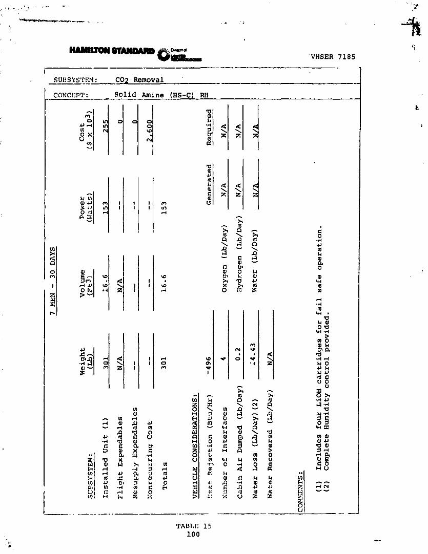
Table 15 defines the subsystem characteristics for the Extended
Duration Orbiter 30-day mission.

HUMIDITY CONTROL BYPASS VALVE
CABIN
CONTROLLER r
SVHSER 7 1 8 5
/ TO CABIN
TEMPERATURE AND HUMIQITY CONTROL
SUBSYSTEM
OVERBOARD VENT
PUMP
FIGURE 2 9
HS-C RH CONTROL
'VHSER 7185
SU13SYS1rF:M : C02 R e m o v a l --.-..- ----- CONC!.:Pll : Solid Amine (HS-C) RH ------- --

SOLID AMINE - (HS-C)/LOW DUMP
SVHSER 7185
The Solid Amine Reduced Removal Subsystem absorbs carbon dioxide
and water in a single bed from the cabin atmosrl-ere and desorbs
it to space vacuum. Complete cabin carbon dioxide partial pres-
sure control and partial relative humidity control is provided.
As a result, the latent heat load on the Shuttle cabin relative
humidity control condensing heat exchanger is less than the HS-C
RH Subsystem. This subsystem is shown schemarically in Figure
3 0 ,
Process inlet air is drawn directly downstream of the relative
humidity control subsystem through the absorbing bed canister.
The air flaw travels through the subsyseem fan and is returned to
the cabin ventilation system. While one bed is absorbing, t',e
secorid bed is desorbed to space vacuum. An ullage compressor is
used to conserve the cabin atmosphere remaining in the on-stream
bed prior to exposure to space vacuum.
Table 16 defines the subsystem characteristics fcr the Extended
Duration Orbiter 30-day mission.

\ T
FROM IBIN TEMPERATURE
AND HUMIDITY CONTROL HEAT EXCHANGER
HS-C
D . 5
HS-C
CONTROLLER 0
SVHSER 7185
VENTILATION DUCT
OVERBOARD VENT
PUMP
-TO CABIN
FIGURE 30
HS-C LOW DUMP

SU
BS
YS
TE
M:
7 M
EN
-
30
D
AY
S
Weig
ht
Vo
lum
e
Po
we
r Cost
(Lb
) (
~t
3)
(W
att
s)
($ x
lo3)
In
st
al
le
d U
ni
t (1)
34
0
15
.2
10
0
24
0
I F
lig
ht
Ex
pe
nd
ab
les
N
/A
N/A
--
O
I., R
es
up
ply
Ex
pe
nd
ab
les
- -
- -
--
0
.
Nc
nr
ec
ur
rin
g C
os
t --
--
- -
2
,70
0
To
ta
ls
3
4 0
15
.2
10
0
m
VE
HIC
LE
C
ON
SID
ER
AT
ION
S:
Yz
2t
Re
jec
tio
n
(Etu
/Hr)
-6
9
Ge
ne
ra
ted
Nu
mb
er
of
Inte
rfa
ce
s
4 O
xy
ge
n
(~
b/
~a
~)
N
/A
Ca
bin
Ai
r D
um
ped
(L
b/D
ay)
0.4
E
yd
rog
en
(L
b/D
ay)
N/A
Wat
er
Lo
ss
(L
b/D
ay)
(2)
9.8
3
Wat
er
(Lb
/Day
)
N/A
N
/A
"I'
k W
ater
R
ec
ov
ere
d
(Lb
/Day
) N
/A
I C
OM
iif NTS :
L
(1)
Inc
lud
es
fo
ur
LiO
H c
art
rid
ge
s f
or f
ail s
a5
e o
pe
ra
tio
n.
(2
)
At
50°F
ca
bin
de
w p
oin
t.

MOLECULAR SIEVE DUMP
SVHSER 7185
The Molecular Sieve Dump Subsystem contains two canisters, each
of which alternately adsorb water and C02 from the process cabin
air and desorb these gases to space vacuum. The Molecular Sieve
Dump Subsystem is shown schematically in Figure 31.
The subsystem is configured such that water and C02 removal are
accomplished in a single absorbing canister which is divided into
two sections. The front part contains a bed of 10 angstrom
molecular sieve for water removal, and the second part contains a
bed of 5 angstrom molecular sieve for C02 removal. The 10
angstrom material dries the process gas to a low water content to
minimize water poisoning of the 5 angstron C02 removal bed. Beds
are sized to go 30 days without regeneration. After every f~lght
the beds must be reconditioned on the ground utilizing the inter-
nal bed heaters and appropriate ground support equipment. For
missions up to 60 days, no in-flight regeneration is required.
For longer mission times, regeneration must be accomplished in
flight.
Process air, from downstream of the Cabin Temperature and Humidity
Control Subsystem, flows through the adsorbing molecular sieve
bed and the subsystem fan and exits back to the cabin. While one

1 I r
HEATER
MS
HEATER B ONTROLLER
1 =
SVHSER 7185
TO VENTILATION DUCT
VENTILATION DUCT
FIGURE 31
MOLECULAR SIEVE - DUMP

bed is adsorbing, the second bed is desorbing to space vacuum.
An ullage rompressor is used to conserve the cabin atmosphere re-
maining i r : the on-stream bed prior to exposure to space vacuum.
Table 17 defines the subsystem characteristics for the Extended
Duration 0;:biter 30-day mission.
SVHSER 7185

SVHSER 7185
SUUSY STCi.1: -- C02 Removal - .-- ---.---- - -
Molecular Sieve Dump CONCEPT: . -..----

MOLECULAR SIEVE - WATER SAVE
SVHSER 7185
The Molecular Sieve - Water Save Subsystem is a four-bed cyclical adsorption system consisting of two silica gel desiccant beds and
two molecular sieve C02 removal beds. The Molecular Sieve - C02 Concentrator Subsystem is shown in Figure 32.
The desiccant beds contain an integral heat exchanger to permit
cooling the beds during the adsorption phase and heating the beds
electrically during the desorption phase. During operation of
the subsystem, cabin process gas is drawn by a fan through the
adsorbing silica gel bed. The silica gel dries the process gas
to a low water content to eliminate water poisoning of the molec-
ular sieve beds. Leaving the desiccant bed, gas passes through
the adsorbing molecular sieve bed where the C02 is removed. On
leaving the adsorbing molecular sieve bed, the process gas passes
the desorbing silica gel bed which is heated electrically. As it
flows through this bed, the dry gas removes the water adsorbed
during the previous adsorption phase of the cycle returning it to
the cabin.
While one molecular sieve bed is adsorbing C02, the second bed is
desorbed by exposure to space vacuum, The molecular sieve beds
are sized for regeneration every 30 days on the ground utilizing
internal bed heaters and appropriate ground equipment. For

FRO
M
CA
BIY
r Ir
FRO
M
CA
BIN
c
t T
O
OV
ER
BO
AR
D
VE
NT
T
O
CA
BIN

SVHSER 7185
missions up to 60 days, no in-flight regeneration is required.
For longer missions, regeneration must be accomplished in-flight.
An ullage compressor is used to conserve the cabin atmosphere
remaining in the on-stream bed prior to exposure to space vacuum.
Table 18 defines the subsystem characteristics for the Extended
Duration Orbiter 30-day mission.

7 MEN -
30
DAYS
Weight
Volune
(Lb)
(pt3
1 Power (
1 )
(Watts)
586 --
Cost
Installed Unit
270.0
16.0
Fli
ah
t Expendables
N/A
N/A
Resupply Expendables
--
--
Nonrecurring Cost
--
--
Totals
270.0
16.0
586 Generated
VEEICLE CONSIDERATIONS:
Fe
at Rejection
(Btc
/Hr)
1,544
Required
-
Nu:
;ber
of Inter feces
4
Oxygen (Lb/Day)
N/A
N/A
Czb
in Air
Dum
ped
(LS/Day)
0.3
Hydrogen (Lb/Day)
N /A
N/A
Xater Loss (Lb/Day)
0
Water (Lb/Day )
N/A
N/A
Water Recovered (Lb/Day)
N/A
I
(1) Requires bake-out at end of mission using special GSE.
I Cost of GSE not included.
!

SVHSER 7185
ELECTROCHEMICAL DEPOLARIZED CONCENTRATOR (EDC) DUMP
The Electrochemical Depolarizsd Concentrator Dump Subsystem
utilizes a fuel cell reaction between hydrogen and oxygen for
removal or concentration of carbon dioxide from cabin air.
Although designed primarily as a carbon dioxide concentrator to
be used in conjunction with a Sabatier reactor and a Water Vapor
Electrolysis ( W E ) unit, the concentrator can be used to remove
carbon dioxide directly by venting carbon dioxide and hydrogen
directly overboard through a suitable back pressure valve.
Complete cabin carbon dioxide partial pressure control is pro-
vided. This subsystem is shown schematically in Figure 33.
Process inlet air is drawn directly downstream of the Cabin
Temperature and Relative Humidity Control Subsystem through the
EDC module and back to the cabin ventilation system by a circu-
lating fan. The same fan is used to cool the EDC module.
Hydrogen from the electrical power supply cryogenic supply or
from an independent supply is fed into the unit at a controlled
flow rate. A subsystem controller regulates the power flowing
into the EDC which controls the C02 removal rate.
Water formed in the module is released to the cabin air stream.
Electrical energy generated by the fuel cell type reaction is
dissipated in an electric heater located in the EDC module system
process air stream.

FRO
M
CA
BIN
w
RH
CO
NT
RO
L
FRO
M
02
GE
NE
RA
TO
R
I r n
I
GI a
n 4
5
TO
TA
BA
TIE
R
n
RE
AC
TO
R
OR
+
CO
NT
RO
L
0
OV
ER
BO
AR
D
DU
MP
I ,A
TE
, .
h
. T
O
VE
NT
ILA
TIO
N
DU
CT
I
&
I

SVHSER 7185
A supply of nitrogen gas is required for purging the subsystem at
start-up and shutdown.
Table 19 defines the subsystem characteristics for the Extended
Dtlration Orbiter 30-day mission.

7
KE
N -
30
D
AY
S n
0 le
cost
14 ($
x
10
3)
1- Weight
Volume
Power
(Lb)
(~t3)
(Wt 2ts)
SL
XS
YS
TE
Y: -
I~stalled Unit
Flight Expendables
N/A
N/A
--
Re supply Ex~endables
Totals
235.0
3 4 7 Generated
Required
VESICLE CONSIDERATIONS:
)?'cat Rejection (Btu/Hr)
2,780
Elr
rrb
er of
Inte
rf a.ces
5
Ca
bin
Air Dumped (L~/D~Y)* 15-63
Water Loss (Lb/Day)
0
Oxygen (Lb/Day)
N/ A
5.~0
i Hydrogen (Lb/Day)
N/A
1.61
1 Water (Lb/Day)
6.6
N/A
1 I >:a
ter Recovered (Lb/Day)
rJ/A
j *C
02
and
H2 Dump

SVHEER 7185
EDC WITH SABATIER REACTOR
The Electrochemical Depolarized Concentrator with Sabatier
Reactor Subsystem utilizes an identical EDC unit to that des-
cribed for the C02 dump system, except instead of dumping C02 and
hydrogsn to space vacuum, these gases are delivered to a Sabatier
Reactor. Inside tne reactor the C02 and H2 mixture is passed
over a catalyst where the gases are converted to methane and
water. The methane and any excess hydrogen is discharged to
space vacuum, and the water after condensing and minor clean-up
is available for drinking or subsequent electrolysis.
This Sabatier Reactor subsystem is shown schematically in Figure
34. The schematic for the EDC is shown in Figure 33. Table 20
defines the complete subsystem characteristics for the Extended
Duration Orbiter 30-day mission.

FIGURE: 34 SABATIER REACTOR
117
SVHSER 7185

SVHSER 7185
EDC With Sabatier Reactor -.- ---. -
EDC WITH WVE AND SABATIER REACTOR
SVHSER 7185
The Electrochemical Depolarized Concentrator integrated with a
Water Vapor Electrolysis unit and used in combination with a
Sabatier Reactor is essentially identical to the individual sub-
systems described earlier. The hydrogen and oxygen generated by
the WVE is supplied directly to the EDC so no external hydrogen
source or oxygen from the cabin is required. Metabolic oxygen
and oxygen leakage makeup is also supplied by the W E portion of
the subsystem. The Sabatier Reactor reduces carbon dioxide to
methane and water as discussed previously.
This EDC/WVE portion of the subsystem is shown schematically in
Figure 35. The Sabatier Reactor subsystem is shown schematically
in Figure 34. Table 21 defines the complete subsystem character-
istics for the Extended Duration Orbiter 30-day mission.

FROM
F
8 CABIN TEMPERATURE
IT
( AND HUMIDITY CONTROL
HEAT EXCHANGER
s
n
&
N2 (PURGE)
-t
WVE/EDC
I MODULE
IT
J
9
TO n
SABATIER
2
1
L--t
REACTOR
F
TO
OR
n
LT
VENTILATION
OVERBOARD DUMP
DUCm
I 1
.1.;

CONCEPT : PDC/WVE With Sabatier Reactor ----.- -.----- - ------

SVHSER 7185
C02 REMOVAL SUBSYSTEM DISCUSSION
The eight candidate C02 Removal Subsystem characteristics are
summarized in Figure 36 for the 7-man, 30-day mission. As can be
noted, all regenerable concepts are lighter and have less volume
than the existing LiOH subsystem for all missions considered.
All but two, the EDC with Sabatier and EDC/WVE with Sabatier,
have a lower total cost over the projected mission period (42
missions). The cost for each subsystem is defined as the sum of
the nonrecurring cost for design, development and certification,
plus the cost for one shipset of hardware, plus the expendables
and spares required to complete 42 30-day missions. The spares
cost is estimated to be equivalent to the cost of one shipset of
hardware over the life of the program. The number of missions
was established by the NASA/JSC.
Since each carbon dioxide subsystem discussed previously affects
the cabin temperature, oxygen supply requirements, water con-
densate supply, etc. in a different manner, it is necessary to
evaluate the candidate on a total ECLS system basis. This was
done and is discussed in the "System" section of this report.

C02
REM
OVA
L SU
BSYS
TEM
S 7
Me
n - 3
0 D
ays
Ne
w
Hea
t V
ehic
le
Co
nd
ensa
te L
eft
Rej
ecti
on
C
abin
(OF
)
Inte
rfac
es
in C
abin
Ib
s/D
av
Btu
/Hr
AD
.B.
AD
.P.
Vo
lum
e C
ost
W
eig
ht
Po
wer
(I
~s
) (W
atts
) vt
3)
(S x
10
6)
N2
E
M O
2 H
z G
SE
n
C z
I m
H
S-C
-
W
"%
U
M.S
. -

TEMPERATURE AND HUMIDITY CONTROL
SVHSER 7185
An analysis of the existing Shuttle Orbiter cabin temperature and
humidity control subsystem shows that it is adequate without any
changes to handle the system modifications proposed for an extended
mission if one of the following C02 Removal subsystems are used:
- LiOH: No change.
- EDC: Cabin temperature dew point will rise 2OF.
- Solid Amine (Either Type): Provides increased heat
rejectiofi c~~acity.
- Molecular Sieve (Low Dump): Provides increased heat
rejection capacity.
If a Sabatier reactor or an electrolysis unit is used with the
EDC subsystem, the cabin temperature will rise as shown in Figure
36 in the C02 Removal section.

PRESSURE AND COMPOSITION CONTROL
SVHSER 7185
A review of the existing Shuttle Orbiter pressure and composition
control shows that it is completely adequate for long duration
missions. No changes appear to be required for other than a
subsystem utilizing an electrolysis subsystem.

SYSTEM DISCUSSION
SVHSER 7185
As discussed in the previous report sections, the selection of a
Carbon Dioxide Removal Subsystem and the decision to utilize a
Waste Water Reclamation Subsystem are ECLS system related dis-
cussions.
Figure 37 defines for each of the leading C02 removal and water
reclamation candidates the possible interactions on a ECLS system
basis.
Figure 38 defines the number of mission possibilities that were
examined primarily with a 7-man crew for 7 , 30, 60, and 90 day
missions. A 3-man, one-day mission was also examined. The
missions studied are'noted in Table 22. The impact on those
systems of 10 men will be discussed later.
In order to assist in compiling the data for the 219 mission
combinations examined, an Extended Shuttle ECLSS Impact Summary
Data Sheet was generated. A copy is shown in Figure 3 9 .
Data from the subsystem data sheets define possible ECLS systems
for use in the Extended Duration Orbiter. With this evaluation
method, various fuel cell operational modes and the effect of
different C02 Removal/Reduction Subsystems (with and without
water receovery) on the system water balance is immediately
apparent.
126

SVHSER 7185
FIGUHE 3 7 - SUBSYSTEM INTERACTIONS
127
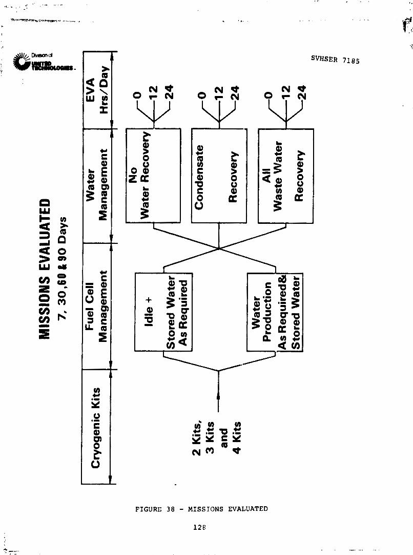
MIS
SIO
NS
EVAL
UATE
D 7
, 3
0,6
0 &
90
Day
s
Sto
red
Wat
er
As
Req
uir
ed
2 K
its,
3 K
its
and
4 K
its
Cry
og
enic
Kit
s -
NO
W
ater
Rec
ove
ry
Fu
el C
ell
Ma
na
ge
me
nt
c-,-
All
1 As prod
uct
ion
R
equ
ired
&
W;zo
E;r
1 <::
Sto
red
Wat
er J
Wat
er
Ma
na
ge
me
nt --
Co
nd
ensa
te
Rec
ove
ry
\,
EV
A
Hrs
/Da
y C
0
f 1
2
\24

TABL
E 2
2
-
OR
BIT
ER
M
ISSI
ON
S ST
UD
IED
30
Day
M
issi
on
- 7
Uen
-
60
Day
M
issi
on
-
7 llen
7
Day
-
7 H
en
1 D
ay - 3
Hen
9
0 D
ay -
7 X
en
Sch
edu
li :
Sch
edu
led
S
ched
ule
d
sch
ed
ule
d
Su
bsy
stem
s -
Idle
Fu
el
Ce
ll
Fu
el
Ce
ll
Idle
Fu
el
Ce
ll
Fu
el
Ce
ll
Fu
el
Ce
ll
Fu
el
Ce
ll
Idle
Fu
el
Ce
ll
r
j ::
C02
S
ub
syst
ems
(8
)
0.
12
, an
d
24
0.
12
. an
d
24
Ho
urs
EVA
H
ou
rs EV
A
C02
S
ub
syst
em
4t
h
0.
12
. an
d
74
C
on
den
sate
Re
cla
ma
tio
n
Ho
urs
EV
A
(8)
C02
S
ub
syst
ems wit..
0.
12
. an
d
24
a11
Was
te W
ater
H
ou
rs E
VA
Rec
lam
atio
n
(8)
0,1
2,a
nd
24
0
,12
,an
d2
4
0. EVA
Ho
urs
EV
A
Ho
urs
EV
A (3
Sy
atem
s)
0,
12
. an
d
24
Ho
urs
EVA
0.
12
. an
d
24
Hours
EVA
0.
12
, an
d 24
Hours
?.'A

EXTE
ND
ED S
HU
TTLE
ECL
SS I
MP
AC
T SU
MM
AR
Y L
IEU
D
ATA
SH
EET
CO
MM
EN
TS
:
SE
NS
IIL
E M
EA
T IE
J~C
TIO
N
mu
/m)
LATE
N-
ME
AT
r~
rt
cit
or
r
cmru
!wr)

SVHSER 7185
Cryogenic oxygen storage is shown on the data sheets for illus-
trative purposes only. Cryogenic oxygen is always required for
ED0 missions to meet fuel cell idle and ascent/descent require-
ments as a minimum. Insofar as the cryogenic kit weights are
actually part of the electrical power system, kit weights are not
included in ECLSS system weights. Fuel cell generated water at
the rate of 21.8 lbsjday as the result of cryogenic 02 usage (at
the minimum fuel cell idle condition of 1 kw) has been included
in the water balance.
Eight C02 Removal Subsystems have been considered for ED0 missions
which are: LiOH, HS-C Relative Humidity Control, HS-C Low Dump,
EDC Dump, EDC/WVE with Sabatier Reactor, EDC with Sabatier
Reactor, Molecular Sieve Dump, and Molecular Sieve Water Save.
The effect of each candidate C02 Removal Subsystem on the overall
watc balance is indicated under the heading "C02 Removal/Reduc-
tion," with subsystems either generating water or dumping water.
Sabatier Reactor contributions to the water balance are indicated
in this block.
Under the heading Water Reclamation," waste water is divided
into two categories; one for urine/wash processing, and one for
condensate processing due to the differing levels of processing
required. For this trade study the TIMES process for urine/wash
recovery was selected with multifiltration processing for conden-
sate water. A 95% water recovery efficiency was assumed for

SVHSER 7185
urine/wash processing, and a recovery efficiency of essentially
100% was assumed for condensate filtration. Note that these
blocks are only filled in if tne water recovered is used to
augment ECLSS requirements. This factor affects systems in which
condensate is produced, but subsequently dumped, such that zeros
appear in the condenser block even though condensate is produced.
Factors affecting the amount of condensate produced include the
level of EVA and the presence or absence of a WVE electrolysis
unit. Each 12 HR/DAY EVA consumes 1.55 pounds of water vapor
which reduces condenser load and contamination accordingly. The
WVE also reduces latent load at the rate of 20.5 lbs/day corres-
ponding to metabolic and EDC 02 requirements.
In addition to the 1.55 pounds of water vapor collected in the
PLSS per 12 HR/DAY EVA, an additional loaded quantity of 14.4
pounds of liquid water is required for sublimator cooling. This
water requirement is the final adjustment to the water balance
prior to determination of an excess or shortage of water. Cabin
condensate quality is reduced by 1.55 pounds for every 12 hours
of EVA.
The system summary on the lower section of the impact summary
sheet shows the component subsystem weights, powers, volumes, and
heat rejection rates. These are summed horizontally to give the
. , total system weight.
SVHSER 7185
Weight and power adjustments are made to subsystem power rcquire-
ments to reflect a cabin fan power reduction made possible through
removal of the LiOH canisters. From the cabin fan power curve
this reduction was estimated to be 11 WDC fcr all non LiOH sub-
systems, and thus this power credit was subtracted from the power
reported on the applicable subsystem data sheets. In addition,
the US-C relative humidity control C02 removal subsystem allows
shutdown of the cabin condenser water separator saving an addi-
tional 25 WDC of power. This reduction was applied in arriving
at the subsystem power for HS-C relative humidity control.
All figures given are relative to the baseline 7-day 4-man
Orbiter. First, C02 subsystems are given weight credit for LiOH
off-loading. This includes the off-loading of 4 men/7 days of
LiOH. Also, LiOH contingency off-loading is also subtracted (for
non LiOH systems) to reflect a 20-hour LiOH contingency versus
the 96-hour contingency required for an all LiOH C02 Removal
Subsystem.
In the fuel-cell-scheduled system evalutions sufficient cryogenic
fuel is aboard to meet all vehicle water demands. An appropriate
fuel cell operating schedule at greater than idle is assumed.
For these cases (30-days and 60-days), subsystems which utilize
cryogenic 02 are penalized for the 02 used under the rationale
that this would otherwise be available for power production.

SVHSER 7185
This penalty is applied to EDC C02 removal and EDC/Sabatier
Reactor C02 removal. Similarly, the EDC/WE produces sufficient
02 to meet metabolic and EDC requirements without draining the
cryogenic 02 stores. The EDC/WVE is actually given a weight
credit for 02 production since cryogenic oxygen is not used for
metabolic or leakage makeup. Note again that these penalties and
credits have only been applied to the fuel cell scheduled system
evaluations, and a comment on such system sheets has been inclu-
ded to flag these cases.
In cases where the water balance indicates a shortage of water,
the necessary additional water is assumed to be brought along in
multiples of the standard Shuttle/Orbiter water tanks. The total
water plus tankage required is listed on the summary sheet under
additional water required.
Total launch weight is determined as the sum of the subsystem
weights, plus stored water and tankage weights. This launch
weight is a delta baseline launch weight, referenced to the 4-man
7-day Orbiter baseline.
Reentry weight is a delta baseline reentry weight for the ECLS
equipment referenced to the 4-man 7-day Orbiter baseline mission.
In view of the fact that the baseline mission includes LiOH C02
removal, non LiOH systems dumping C02 to space vacuum result in
delta return weights lower then baseline mission weights in many

SVHSER 7185
cases due to this C02 dumping (versus C02) storage for the base-
line mission. Any stored water taken up is assumed to be used or
dumped prior to return in the reentry weight determinations with
empty tanks returning.
Data sheets are supplied in Appendix A for all the missions
listed in Table 22. All data compiled is based on a delta impact
when compared to the baseline Shuttle Orbiter mission of 4 men
for 7 days. This data reference point is illustrated in Figure
40 for the delta launch and delta reentry weight.
The delta mission effect of launch weight, landing weight,
volume, power, and heat rejection for typical missions are shown
in Tables 23 through 27. Examination of these tables and appli-
cation of appropriate penalties will determine the optimum C02
removal subsystem and also determine when waste water reclamation
trades off against carrying stored water. Each system must be
further evaluated in regard to such factors as numbers of vehicle
interfaces, GSE required, safety, radiator impact, etc. Again,
it must be emphasized that these numbers reflect only ECS delta
weights.

FIGURE 40 - A LAUNCH AND A
'i SVHSER 7185
I
REENTRY WEIGHT

Cop Subsystem
LiOH HS-C RH Control HS-C Law Dump EDC EDC/WVE Sab EDC With Sab Mol Sieve Law Dump Mol Sieve Water Save
TABLE 23 - DELTA LAUNCH WEIGHT SUMMARY c
30 Days - 7 Men 60 Fuel Cell Idle Fuel Cell Scheduled Fuel Cell Id.
0 MH EVA 12 MH EVA 24 MH FVA - 24 MH EVA O M H EVA l2 MI
990 7 99 9
138.6 236.2
-167.0 351.8
89.1 94.0
LiOH 1412.9 2201.8 3000.8 2745.8 432: - HS-c RH Control 1899 9 2639 9 3319.9 3699.9 5175
11s-C Low Dump 1350.8 2149.7 2948.7 2425.5 402: g EDC 451.3 1250.2 2039 .? Not Applicable 716.0 2301'
E D C ~ Sab 1466.9 2240.8 3029.8 2416.6 3961 d ' EDC With Sab 326.9 1015.8 1804.6 341.6 171, $ 2 ~ o l ~ i e v e ~ o w hmp 1451.3 2230.2 3039.2 2676.0 423
Mol Sieve Water Seve 661.2 1615.0 2374.1 1490.9 299!
L ~ O H 1287.0 1285.9 1284.9 2380.0 237~ 2
YS-C RH Control 354.4 964.4 1644.4 385.1 16c ,, FiC Low Dump 434 3 433.2 1172.2 479.7 47 354.8 353.7 352.7 Not Applicable 400.2 3%
3 3 EDC/WVE Sab 675.4 674.3 1213.3 720.8 71f. d " EDC With Sab 470.4 469.3 468.3 515 . 8 5q 4 Mol Sieve OW Dump 384.8 428.7 1182.7 430.2 5
Mol sieve Water save 389.7 388.6 607.6 435-1 43:

SVHSER 7185
TABLE 23 - DELTA LAUNCH WEIGHI SUMMARY SmET
90 Days- 1 Day- 60 Days - 7 Men 7 Men 7 Days - 7 Men 3 Men
Fuel Cell Idle Fuel Cell Scheduled Fuel Cell Fuel Ce l l Scheduled Fuel Cel l ieduled Idle Idle
A 24 MH EVA 0 MH mA 2 EVA 0 MH EVA 0 WA 0 MHmA 2 MH EVA 24 MHEYI\ 0 MH EVA L -- -
990 7 2038.9 2038.9 191.4 191.4 191.4 -102.6 82.6 93 9 99.9 99.9 99.9 99.9 99.9 138.6 138.6 138.6 138.6 138.6 138.6 236.2 413.3 413.3 59.1 59.1 59.1
-167.0 -713.7 -713.7 379.8 379.8 379.8 351.8 528.9 528.9 171+.8 174.8
174*8 89.1
r
89.1 71.4 89.1 89.1 89.1 89.1 94.0 94.0 94.0 94.0 94 .O 94 .O
. . . 400.2 399.3 Not Applicable 438.1 720.8 718.9 758.7
NO^ Applicable
~ o t , Applicable

L i O H HS-C RH Control HS-C Low Dump E D C ~ Sab EDC With Sab Mol Sieve Low Dump Mol Sieve Water Save
DELTA RE-ENTRY WEIG. ',
d . .
30 Days - 7 Men 4 .i
Fuel Cell I d l e Fuel Cell Scheduled Fug
COp Subsystem 0 MH EVA 12 MH EVA 24 MH EVA 0 Mlq EVA 12 MH EVA 24 MH EVA - 0 MH +:
LiOH HS-C RH Control HS-C Law hunp E'X EDC/WVE Sab ZDC With Sab Mol Sieve Low Eump Mol Sieve Water Save
LiOH HS-C RH Control MS-C Lm hmp EDC EDC/WVE Sab EDC With Sab Mol Sieve Low Dump Mol Sieve Water Save
268.: 63,.: 23
Not Applicable -48 : 45 '
-56.'; - , 3 ki-
- 1c .- 264 . -51 t. - 4; ..
Not Applicable - 5c 1. -16 ! -3E. -4lf -4@
B +:
ir.

SVHSER 7185
!IT SUMMARY SHEXT
90 Days- 1 Day- 60 Days - 7 Men 7 Men 7 Days - 7 Men ? Men
e l Cell I d l e Fuel Cel l Scheduled Fue l Cell Fuel Cel l Scheduled Fuel Cell I d l e I d l e
EVA 12 MHFNA O M H W A 12 M H E V A O K H E V A O M H X V A 12 MHEVA 24 MHEVA O M H E V A - ---
Not A q l i cable
Not Applicable
Not Applicable
Not Applicable

TABLE 2 5 - DELTA VOLUME SUMMARY smr
30 Days - 7 Men 60
COp Subsystem
L i O H HS-C RH Control
Z HS-C Low hmp i% w
EDC
0 k Z P: Mol Sieve Low Dump
Mol Sieve Water save
1, i OH :IS-C Control HS-C Low Dump
EDC/WVE Sab 2 EDr: With Sab
Mol Sieve T,OW Dump Mol Sieve Water Save
LiOH HS-C RH Control
H HS-C Low Dump
EDC With Sab
Mol Sieve Water Save
Fuel Ce Idle
21+ MH CYA
133.4 86.4 85.0 81.5 91.3 85.0 87.6 87.5
113.4 86.4 86.0 61.5 99 3 67.0 95.6 74.5
75.4 57.9 48.0 23 5 54.3 34.0 64.6 43.5
F u e l Cell Scheduled Fuel Ce l l Id:
0 MH KVA 12 Mi LVA 24 MH EVA 0 MH ETA - 12 K
Not Applicable
Not Applicable

SVHSER 7185
TABLE 2 5 - 90 Days- 1 Day-
60 Days - 7 Men 7 Men 7 Days - 7 Men 3 Men Fuel ? e l l Idle Fuel Cell Scheduled Fue l Cell Fuel Cell Scheduled Fuel Cell
Td l e Idle 0 MI PYA 12 MH EVA 0 M1-I l'N.4 12 MI TWA 0 MI EVA 0 bQ1 :TA 12 MI1 F?A 24 M)I EVA 0 MH EVA
Not Applicable Not Applicable
Not Applicable 34.7 Not Applicable 51.5 45.2 40.8 w'. 7

TABLE 26 - DELTA WWER SUMMARY SHF&
Go ,
uel (!el l S -hc.duled Fuel Cell I d 1 30 l ~ y s - 7 Men
.e FI Fuel i ' e l l Id1
COP Subsystem 0 Em EVA 12 MH EVA 214 MI! EVA 0 Mi EVA -- 12 MI1 EVA - 0
117 59 336
2379 3 78
63 5 7 ,
LiOH HS-C RH Control HS-C Lm Pump EDC Dump SDC/WVE Sab ELC With Sab Mol Sieve Low Dump Mol Sieve Water Save
L i O I i HS-C RH Control IIS-C Low Dump EDC Dump EDC/WVF, s6b nnn T.T. CL .. : ,,. Cab Mol Sieve Low Dump Mol Sieve Water Save
Not Applicab1.e
I, i 0:: !IS-T RH Control 11s-C T.c?w ' lump EW Lump EDC/WVE Sab FDC W i t h Sab Mol Sieve ! s w hr?~
Mol Sieve 'dater Seve
Not Appl icable

TABLE 26 -- SVHSER 7185
3LTA POmR S W Y SHEET
90 Days- 1 Day- 60 rays - 7 Men 7 Men 7 Days - 7 Men 3 Men
Fuel Cell Id le Fuel Cell Scheduled Fuel Ce l l Fuel Cell Scheduled Fuel Cell I d l e I d l e
MHEVA O M H Z V A E bIH EVA 0 MH EVA 12 WEVA O W W A O M H E V A 12 MHEVA 24MHEVA OMHWA ,-
Not Applicable
315 4 17 404
Sot Applicable 651 2693 693 378 890
Not Applicable
Not Applicable

TABLE 27 - DELTA HEAT REJECTION SUMMARY SE
36 Days - 7 Men 60 DI Fuel Cell Id le Fuel Cell Scheduled Fuel Cell Id le
0 MH EVA
761 -619 - 196 2741 4462 3344 -309 1507
24 MH EVA
761 -619 - 106 2741 4462 3344 -309 1507
0 MH EVA 12 MH EVA 0 MH EVA C% Subsystem
LiOH s HS-C RH Control
. HS-C low Dump ' o iZ/WVE Sab s u EDC With Sab
W s Mol Sieve Low Dump Mol Sieve Water Save
842 -619 -2 5
Not Applicable 2 822 4543 3424 -228 1588
LiOH s HS-C RH Control
: g HS-CLOW Dump EDC a
a EDC/WVE Sab i d 0 s u EDC With Sab
; P Mol sieve Lm D mp Mol Sieve Water Save
LiOH HS-C RH Control
8 HS-C L3w Dump
EDC/WVE Sab EDC With Sab
4 Y Mol Sieve Low Dump
Not Applicable
ffi Mol S i eve Water save

SVHSER 7185
TABLE 27
HEAT FWECTION SUMMARY SHEET
60 Days - 7 Men d Fuel Cell Idle Fuel Cell Scheduled
' MH EVA 0 MH EVA 12 MH EVA 0 MH EVA
842 -619 -25
2822 Not Applicable 4 543 3424 -228 1588
3813 5 534
Not Applicable
4416
90 Days- 7 Men 7 Days - 7 Men
Fuel Cell Fuel Cell Scheduled Idle
0 MH EVA 0 MH EYA 12 MH EVA 24 MH EVA
Not Applicable
Not Applicable
1 Day- 3 Men
Fuel Cell Idle
0 MH EVA

.__ ,
IMPACT OF 10 MEN
SVHSER 7185
The impact of a 10-man crew was investigated, and it was con-
cluded that it was very unlikely that a ECLS system would be
designed around this size crew for Extended Duration Orbiter
missions. Instead, the ability of the 7-man ECLS system to
handle a crew size of 10 men was investigated.
For 10-man operation the C02 Removal Subsystem must handle an
additional C02 load of 6.33 lbs/day. If the C02 removal rates
were to remain constant at a 7-man rate, emergency conditions of
15 mmHg PC02 will be reached in approximately 26 hours. This is
shown in Figure 41. In actuality, this time will be slightly
longer for the HS-C Solid Amine and Molecular Sieve Subsystems
due to the increase in sorption capacity with increasing C02
partial pressures. EDC C02 removal is affected very little by
increases in PC02 above 5 mmHg; and, therefore, its emergency
limitation will be very close to the 26 hours.
For extended operation (longer than 26 hours) at a 10-man rate,
process modifications are required to keep the C02 partial pres-
sure within limits. For HS-C Solid Amine, C02 control to 5 mmHg,
and complete relative humidity control may be maintained by
changing the bed cycle time from 20/20 to 10/10 (minutes adsorb/
minutes desorb). No detectable changes in cabin PC02 or dew
point will be noted at the 10-man rate with this change.

SVHSER 7185
Unlike HS-C Solid Amine, the Molecular Sieve C02 Removal Subsystem
will not maintain C02 partial pressures without changing air flow
in addition to cycle time. This would require an oversized fan
or an additional fan capable of providing the 10-man process air
flow. This fan(s) would be required to provide a 43% increase in
air flow for the 10-man case. This size fan was not included in
this study.
The EDC C02 Removal Subsystem will be capable of maintaining C02
partial pressures by increasing the current density. The trans-
fer index will decrease, however, but C02 partial pressures will
be maintained.
C02 partial pressures may be maintained at 5 mmHg for the LiOH
subsystems by-charging out the LiOH cartridges at 3.2 hour
intervals versus 5.5 hours for the 7-man case.
It should be noted that it is possible to operate the LiOH system
in conjunction with the Regenerative C02 Subsystem without re-
qulring any process modifications for a 10-man crew retreation
assuming an ample supply of LiOH cartridges are available.

SVHSER 7185
TIME (HR) SINCE 3 ADDITIONAL MEN ENTER CABIN
Figure 4 1 Cop P a r t i a l Pressure Versus Elapsed Time Fran Addi t ion o f 3 Men t o Cabin
1 4 4

VEHICLE CONSIDERATIONS
SVHSER 7185
Three factors that involve the present Shuttle Orbiter to operate
on extended duration missions were investigated and are discussed
in the following paragraphs. These are:
- Impact on existing Shuttle equipment
- New subsystem locations
- Spares and redundancy requirements

SVHSER 7185
IMPACT ON EXISTING SHUTTLE EQUIPMENT
The present Shuttle Orbiter ECLS system was reviewed as to its
capability to accomplish a 30-day mission. These comments are
noted in the following paragraphs for each major subsystem.
Freon Cooling Loop
No changes are required as the subsystem is already designed for
fail operational/fail safe. Both coolant loops normally operate
and non-static devices are all redundant. If there is a failure
in both pumps, for example, or a leak in one loop, then a single
loop degraded mode of operation is the fail safe condition.
Atmospheric Revitalization Subsystem (ARS)
Requires one spare C02 PP sensor (located on the cabin fan
package). This sensor has three captive fasteners and has
no special shimming requirements.
The present ARS configuration is fail safe.
If the HS-C RH control system is used for C02 removal, then
the fan separator is not used, and only one fan separator is
required for the fail safe requirement.
Cabin fans are redundant and, therefore, fail safe.
The debris trap for the cabin fan needs to be cleanable in
flight or replaceable in flight. The present Orbiter debris
trap is cleanable, assuming that a properly design vacuum

SVHSER 7185
>,
cleaner is available. The debris trap is not in flight
replaceable at this time. It is recommended that it be
redesigned for long term missions.
6) A Regenerable C02 Removal system should be incorporated as
discussed in this report. If a LiOH C02 Removal Subsystem
is used, more LiOH cartridges are required for longer dura-
tion missions, and space must be alotted for the cartridges
required.
Waste Management Subsystem
1) The commode is sized for 210 man days. Additional commodes
will be required for 60 and 90 day missions. For fail safe
a four day supply of fecal storage bags are required. The
used bag volume will fit in a failed commode.
2) Waste storage tanks are defined as static devices and,
therefore, are fail operational/fail safe already by defini-
tion. Waste water may be dumped overboard at regular inter-
vals so the tank size will not change for long duration
missions unless the dump cycle has to change for some reason.
3) A biocide injection device must be added since the baseline
method of placing biocide in the waste storage tanks prior
to launch does not work for longer missions which will
require dumping of waste water during the mission.
4) If a waste water recovery system is used which produces a
concentrated waste liquid, provisions for dumping this
liquid into the commode is required.

Avionics Cooling
SVHSER 7185
Non-static devices are redundant. If, for example, both fans in
one avionics loop fails, there is sufficient overlap with the
other two avionics loops to cool critical components. Therefore,
the avionics systems are already fail operational/fail safe.
Potable Water Tanks
Tanks may have to increase in number based on system considera-
tions, but since they are static devices, the tanks are already
considered fail operational/fail safe. Additional tankage will
have to be located below the payload bay. The addition of
heaters to these tanks must be considered.
Nitrogen and Oxygen Supply
More tanks will be required for longer missions. Also, each tank
should have its own valving rather than the present system which
has one valve for two tanks.
Cabin Pressurization
Redundant 14.7 psi and 8.0 psi regulators already exist in the
cabin and provide fail operational/fail safe for both 02 and N2.
The upstream 100 psi 0 2 regulators are redundant and if both fail
closed, 02 may be fed through the emergency breathing system or
airlock to the cabin. Therefore, this part of the system is
actually fail operational/fail safe. The nitrogen 200 psi regu-
lators are redundant, and if both loops fail, then cryogenic or
auxiliary oxygen can be used to fail safe.

SVHSER 7185
Wash Wbter
More soap and more towels will be required. No changes to the
waste storage tank will be required as long as water can be
dumped overboard.
IMU Coolinq
The cooling loop in this system is now supposed to be run open
loop. If this is the case, a cleanable or replaceable filter
should be provided near the inlet from the cabin.
Water Coolant Loop
Two redundant loops are installed with one operating. The pri-
mary loop has redundant non-static devices. If, for example,
both primary pumps fail, then the secondary loop can be used to
fail safe.
Trace Contaminant Control
The only trace contaminant control system now in the Orbiter is
the charcoal in the LiOH cartridges. For longer missions a trace
contaminant cont.ro1 system will have to be added as discussed in
this study.
Nitrogen Gas Storage
Two additional gaseous storage tcaks are required together with
appropriate valving.

SVHSER 7185
NEW SUBSYSTEM LOCATIONS
Many changes to the baseline Shuttle Orbiter ECLSS have been
discussed as desirable for Extended Duration Orbiter missions. A
limited investigation as to where this equipment might be located
was conducted as follows:
Trace Contaminant Control
Install charcoal beds in LiOH canister during on-orbit operation
if a regenerable C02 removal subsystem is selected. Otherwise,
install unit in cabin air ventilation duct or on cabin wall.
Waste Management
Add biocide tank adjacent to existing waste water tanks.
C02 Removal
Install subsystem under floor next to waste storage tankb in
present LiOH storage area. Vacuum duct locations will require
additional study.
Waste Water Processing
Install subsystem under cabin floor. This location hz.s m t been
examined thoroughly and will require additional study.

Nitrogen Gas Tanks
Install tanks urvier payload floor.
SVHSER 7185
Water Tanks
Two additional potable water tanks, if required, can be installed
under the cabin flow. Additional tanks would have to be in-
stalled under the payload floor area with appropriate studiez
conducted to determine the need of providing heat to keep tanks
from freezing. Operation of the fuel cells to produce water
could trade off better and will require further study.

SPARES AND REDUNDANCY COMMENTS
SVHSER 7185
The baseline Orbiter ECLSS provides, as a minimum, a fail safe
backup. This backup provides for the launch/re-entry phases as
well as a safe return, should a failure or emergency arise. Many
of the new subsystems being considered for the extended missions
are not able to function during the launch and recovery phases
since they need a vacuum source or cannot operate in a high
multidirectional "g" field, thus ths backup for these phases wil'
still be required even if spares or redundancy is added to the
subsystem.
For this study, redundancy and in-flight spares for new subsys-
tems have been assumed to be zero. This very closely approxi-
mates the real 7 to 30 day missions but may be optimistic for the
60 and 90 day trade-offs. However, as the trade-off between
subsystems will be made on a certain selected mission length, the
redundancy affect will have about the same smcl.l percentage
affect on each canidate's weight and its volume. Each subsystem
penalty will increase only a slight amount when in-flight spares
are considered, and thus the relative subsystem-to-subsystem
trade affect will be small. In-flight expendables have been
included in the various missicn length values as they are neces-
sary to complete a given mir . ' on .

SVHSER 7185
APPENDIX A
EXTENDED SHUTTLE ECLSS IMPACT SUMMARY DATA SHEETS


k, QQQ '3

EX
TEN
DE
D
SH
UTT
LE
EC
LSS
IM
PA
C?
S
UM
MA
RY
Cq
SU
BS
TO
TAL
REC
TO
TAL
4 G
EN
TO
TAL -
MIG
HT
IL
U)
0 m
m"H
.""/
c4w
EvA
1
1 m
m"H
."n/D
my
iV*
n urn H
RI
VS
/~
EV
A
POWERIDC w
mI

EX
TEN
DE
D
SH
UTT
LE
EC
LIS
IM
PS
CT
S
UY
MA
IIY

EX
TE
ND
ED
S
HU
TT
LE
E
CLS
S
IMP
AC
T
SU
MM
AR
Y
Ce
SU
u T
OT
AL
R
EC T
OTA
L 0
, G
EN T
OTA
L -

ORlGlNAl. PACE !' OF POOR QUALITY


4 QQQ
eet

[
I
1 2;
il &I ='I U ;I I*
I !
? @
A { t 7 :
I . . , n 1 S, :. ! f l ; I r . !
: i
; jl


EX
TE
ND
ED
S
HU
TT
LE
E
CLS
S
IMP
AC
T
SU
MM
AR
Y
30
Da
:s -
No
Wat
er
Rec
lam
ati
on
- F
uel
Ce
ll I
dle
- ESC
R.H
. C
on
tro
l C
02
Rem
oval
?.*: bm
nc
. (M
I m
*es
in
LB
S/D
AY
I I c
&&
f ;&
C*
R
LM
Ov
AL
R
ED
UC
TId
R
EC
Y~P
IION
C
ON
SU
MP
TIO
N
WA
TER
E
VA
US
E
SA%E'?&
1- T
OT
AL
S
Rt-
EN
TR
Y W
K;n
i 30 D
AY
UIM
MA
RY
t
o2
Suf
i T
OT
AL
H
gO
REC
TO
TAL
02
GE
N T
OTA
L
WF
lGH
T (
LB
SI
t+.F%
m&
H9.9
0
C ~
on
tbm
/Dn
y E
V~
+
y').
y 1
- C-
1800
1199.9
35'3.5
I2 M
an
Mw
n/D
aY
EV
A
25
40
26
39.9
66
7.5
+9
9.9
24
Man m
un
/oq
EV
A
-0
0 3220
3319.4 --
-- -
---
915.5
PO
WE
R
DC
%rr
s I
+I17
0 0
--
il
l7
V
OL
UM
E (
F*
.~
I O
Ma
n H
ou
n/~
ay
EV
A
+?
.4
0
0
+$9
+51
.L,
-
12
M9n
Ho
urs
/ y
EV
A
+L .i)
34
Mo
n H
ours
/&
EV
A
-- P
-- - +
T
i 0
+2.4
C
+
72.:
is-
--- +6
6.:

I g l 1 3 QQQ


ORIGINAL PAGE IS OF PQOR QUALITY

eftrc;il;jhL g..i.-Z i" E OF POOR QUALITY
8 $1 QQQ (1 In

ORffilNAL PAGE IS OF POOR QUALITY

EX
TE
ND
ED
S
HU
TT
LE
E
CLS
S I
MP
AC
T
SU
MM
AR
Y
SY
STE
M
30
Days - N
o Water Reclamation -
Fuel Cell Idle -
EDC
/WV
E with Sabatier Rea
ctor
C
O2 Re
mova
l/Re
ductio
n
Wat
mr
kh
m IA
ll r
ata
s in
LW
/DA
Y)
IC
30
MY
-MA
RY
I
C0
2 S
UB
S
TOTA
L H
fl
REC
TO
TAL
% G
EN
TO
TAL
h- TO
TALS
R
E-E
N7R
Y
WT
tW
WE
IGH
T 1
LDS
I 0
m")(
.un
/~q
EV
A
12 M
an M
oun/D
ay
EVA
H M
an H
wrs
/my
EV
A
PO
WE
R ( D
C W
ns
)
SEN
SIB
LE
n A
T R
EJE
CT
ION
hu
/HR
l
LA
TtN
T H
EA
T R
EJEC
TIO
N
IBTU
/HR)

11 QQQ I"

81 1 QQQ

OHIGII\IA~ 5 - . . 1
OF! POOR QUALITY
QQQ


ORIGINAL PAGE IS OF POOR QUALITY
E E E

a QQQ
E E I


EX
TE
ND
ED
S
HU
TTLE
E
CLS
S I
MP
AC
T
SU
MM
AR
Y
30 Days - N
o Water Reclamation - F
uel Cell Scheduled -
EDC/WVE w
ith
Sabatier Reactor-COP Removal~Reduction
1.
E;)C
/WVE
given credit
for
O2 generation
LQmntDc W
thl
rolU
ME
I m
.3 I
0
Mon m
/m
EVA
lf
M=
nn
am
/ 2.
rwon
h""E
Kt

11 QQQ

LT1+
S'SK6+ 6'6TE
E+
OZZE
S'L
99t S'6SC+
+%
%--
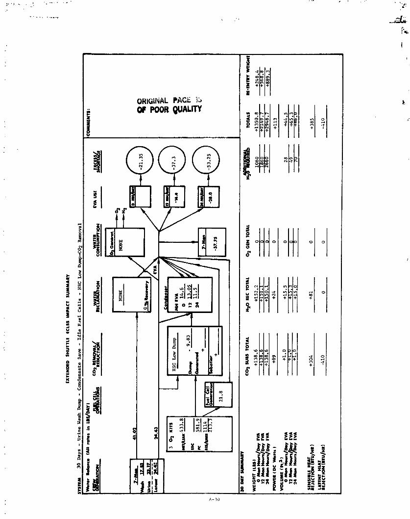
EX
TEN
DE
D
SH
UTT
LE
EC
LSS
IM
PA
CT
S
UM
MA
RY
STE
M
30 D
ays
- Urine W
ash Dump - C
ond
ensa
te S
ave
- Id
le F
oe1
Cell
s - H
SC
Low
hp
-CO
2 R
emov
al
*for
hb
nc
m I
AII
mte
s a
n L
~/M
Y)
- -
--
TOTA
LS
RE
-WR
Y W
EK
im

EX
TEN
DE
D
SH
UTT
LE
ECLS
S IM
PA
CT
S
UM
MA
RY
B~
M 30 Days -
Urbe Wash D
ump
- Condensate Save
- Idle Fuel Cells -
Mol Sieve L
ow D
umpC
O2 Removal
kte
r b
hc
m (
All
ret
or k w
/br~
1
n
t4ol Sieve L
ow
MH
EV
A
Dum
p
-39.3
012.6
~u
np
-
11.83
12 '
11 05 0
I +
--
-55
.25
--
TOTA
LS
Rf-
EN
W m
wt
col
rum
TO
TAL
n+
arc
ro
tr~
0
2 G
EN
TO
TAL
ml
Gw
tias
) 0 r
h~
(r
vr
/~.l
EV
A
12 &
m~anr/m
NA
24 M
an )lurr
/m EV
A
WIW
LR
(M n
kn
sl

4 QQQ

EX
TE
ND
ED
S
HU
TTLE
E
CLS
S
IMP
AC
T
SU
MM
AR
Y
yw
m
30 Days - U
rin
e W
ash
Dum
p - C
ond
ensa
te S
ave
- Id
le F
uel
Ca
lls
- EDC - C
02
Ren
mva
l
YY
I1.r
k
bu
o (
AM
mto
s I
n L
B%
AY
)
L
*c;.nra.
NONE
NONE -4
I-Ym
41.0
2
mx
&L
I
ck
.a
34.4
3
3 ol r
ln
10 M
Y uu.urr
C*
SUB
S TO
TAL
nc
TOTA
L ~
GE
Nt
OW
l48
'wu&
KIW
~R
~U
C rn
m)
VO
LU
ME
I fr
.3 1
0 Man )
(ou
rr/m
y
EV
A
z=
aE
TOTA
LS
lt-ENm
mw
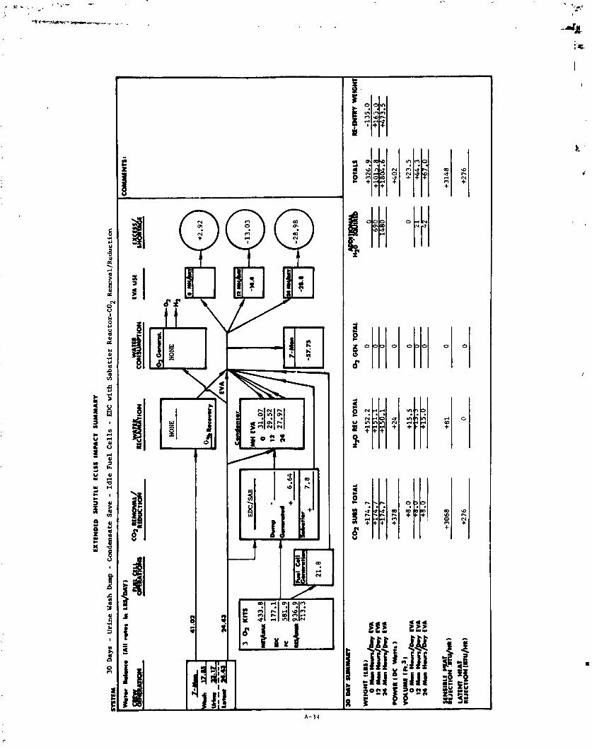
EX
TEN
BE
D
SM
UTT
LE
EC
LSS
IM
PA
CT
S
UM
MA
RY
L1lnM
30 Days - U
rine Wash
Dum
p - C
ondensate Save -
Idle Fuel Cells - E
M:
wit
h Sabatier Reactor-C02 Removal/Reduction
I c
I mlo
nr i~
u)
o ~
*II)
O/D
W
EVA
12 m
aII
am
n/D
=y
CW
rn
h)C
.rJ
D=
y E
VA
I SE
NS
IBLE
VT
+
30
68
+
81
0
RE
JU
TIO
N
I LA
TtW
MEA
T R
EJE
CT
ION


ZZE

EX
TE
ND
ED
S
HU
TT
LE
tC
LS
S
IMP
AC
T
SU
MM
AR
Y
~S
RM
30
Days
- All
Wat
er
Rec
lam
tio
n -
Idle
Fu
el C
ell
s - H
X - Lm D
ump-
Cop
R
em~
va
l
*rn
(A
II rr
cr~
k L
WM
YI
C-M
-L R
ED
oc
vId
ac
w&
~on
EVA
uu
&fp&
ca
m,
C*
SU
~
TOTA
L v RE
C T
OTA
L % G
EN
TOTA
L &-
--
TOTA
LS
M-E
Nlm
~m
a

EX
TE
NM
D
IOU
TlL
E
EC
LSS
IM
PIC
T S
UM
MA
RY
nn
m
30 D
ays
- All
Ua
ter
Rec
lam
atio
n -
Idle
Fu
el C
ell
s - M1
Sie
ve
L,w
Dump
-CO2
R
mv
al
Ilkt.r
WIIY
. (l
ilt
ms
in
ui/
&~
)
-
- c*
ru
u T
OTA
L y r
tc T
OTA
L 4 Gm
TOTA
L -


! ~ i j ' 3 A - J I

E&
TEN
OE
O
SH
UTT
LE
EC
LSS
IM
PA
CT
S
UM
MA
RY
BT
tM
30 Days - A
ll W
ater
R
ecla
mat
ion
- Id
le F
uel
Cel
ls - E
DC w
ith
Sab
ati
er R
eact
or-C
02 R
emov
al/R
edu
ctio
n
%te
r k
bru
o
tAII
.oh,
in U
S/M
Y)
TIME
S
!%,- o
m 3
-4
3
W.U
3 q K
ITS
433.8
= u,
Dum
p
-- rc
582.9
-(;rrrec.d
WlG
MT
tlW
l 0 m
~n
-/b
EV
A 12
Ik
n ~
.un
/~o
l -1
14 M
a, H
OW
S/D
~~
E
VA
K)W
IIR
IDC
H
kn
s
LATE
NT
HU
T
RE
JEC
lBO
N IB
TU/H
R)

xi 81 QQQ

8 88 ELL

A
'{ijlIj 5 2 3 (I)
+ 7
g

EX
TE
ND
ED
S
HU
TlL
l E
CLS
S I
MP
AC
T
SU
MM
AR
Y
B~
M 60 Days - W
aste Water D
ump
- Fuel C
ell
Sch
edu
led
- HSC
Low
Dump C
O,
Ren
mva
l
kte
r k
bno
(All
mh
s in
~T
Ic
IN
C
* R
EM
OV
AL
EVA
USE
J&
##&
-
muc~~d
IEC
Y~
~IO
N
C*
SUB
S 1
0T
AL
RE
C TO
TAL
0,
GE
N T
OTA
L bv=
TO
TALS

4 QQQ

; ?I? ,I * u v l
T $ 5 (I)
g

rsr - {& - g 'Wjrrr 1 1 1 ;a
D $ o r x I aogx 9: e E w 53

1 QQQ

EX
TE
ND
ED
S
HU
TTLE
EC
LSS
IMP
AC
T
SU
MM
AR
Y
I 6
0 M
Y U
YY
'I*
C*
SUBS T
OTA
L M+
RE
C TO
TAL
0,O
arT
OT
AL
1. E
DC
~
given credit
for
O2 generation.

EX
TE
ND
ED
S
HU
TT
LE
E
CLS
S
IMP
AC
T
SU
MM
AII
TOTA
LS
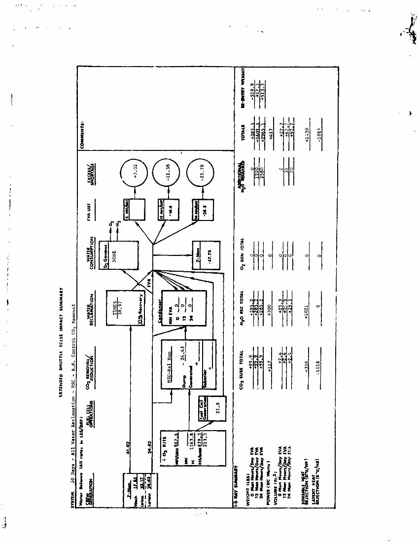


(IIIENAL PAGE IS OF POOR Q U ~
4, QQQ 8 l!! 3' -44 Si-

ORGIML PRGE IS OF POOR QU-
xi $1 QQQ F1 + .+
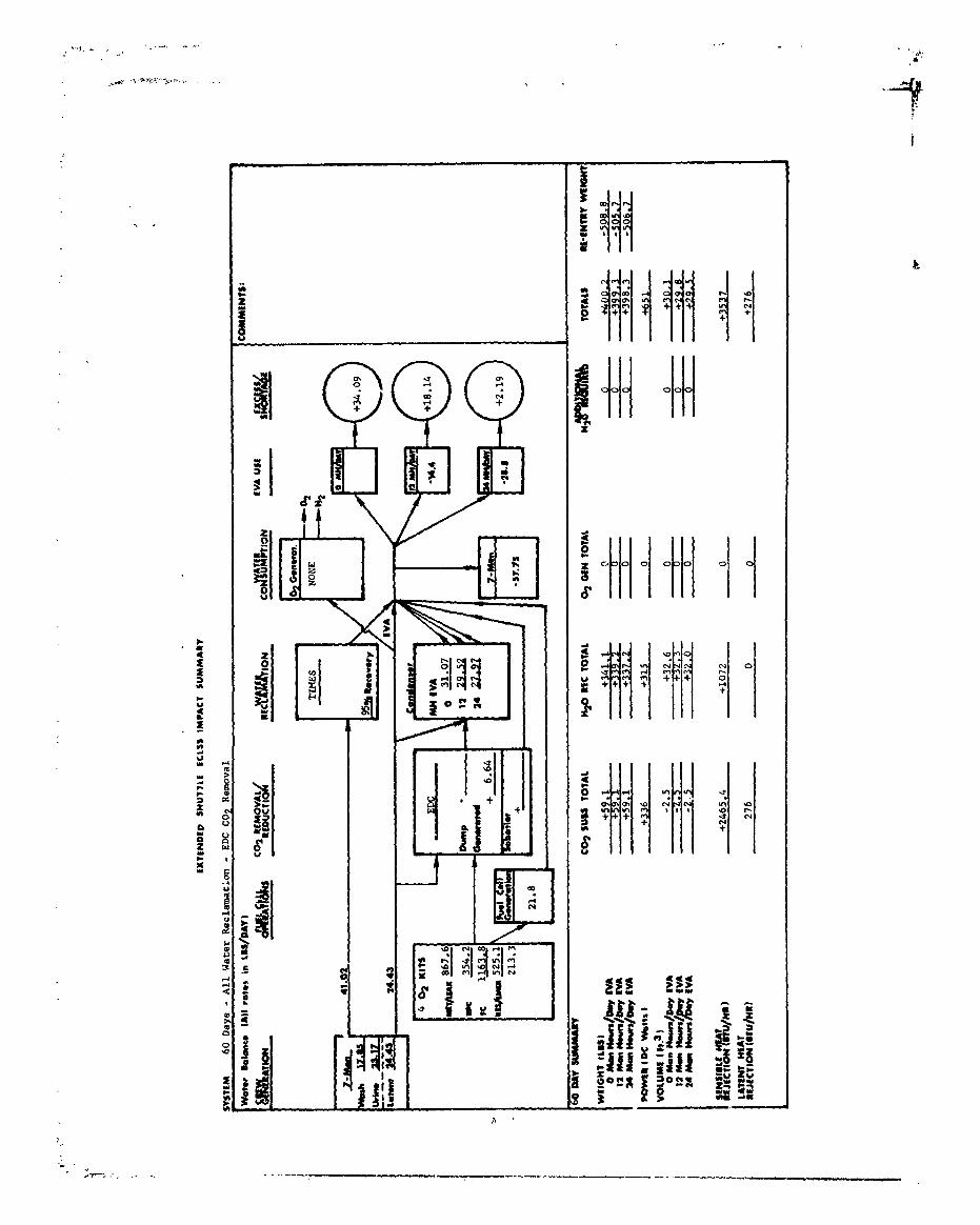
QQQ I-I + m +

EX
TEN
DE
D
SM
UTT
LE
ECLS
S IM
PA
CT
S
UM
MA
RY
STE
M
6G
Day
s - A
ll W
ater
Rec
lam
atio
n E
DC w
ith
Sa
ba
tier
Rea
ctor
Cog
R
ern
oval
/Red
uct
ion
Wat
er
Bal
ance
(A
ll r
ato
r in
LU
/DA
YI
10
DII S
lmM
mV
C
01
SU
BS
TOTA
L R
EC T
OTA
L %
GIN
TO
TAL
4-
JVEI
GW
T (L
U)
0 ~
o,
~u
r/
~q
11 M
om ~
ou
rr/~
Oy
C
VI
24 M
an n
DLm
/Day
E
VA
PO
WE
R f
DC
Hk
ttr I
TOTA
LS
RE
-EN
TRY
Wll
On
l

EX
TE
ND
ED
S
UU
TIL
E
EC
LSJ
IMP
AC
T
SU
MM
AR
Y
1tM
6
0 D
ays
- A
ll U
ater
Rec
lam
rrtl
on - EDC/WVE
wit
h
Sa
ba
tier
R
eact
or C02 R
emov
al/R
edu
ctio
n
- -
0 M
Y W
MM
IRY
C
O?
WU
TO
TA
L
n20 RE
C T
OTA
L O
2 GCN T
OTh
L ~
~n
TO
TALS
R
E-EN
TRY
WE-

ORIGINAL ?ME 13 L) . OF POOR Q U A L ~

EX
TE
ND
ED
S
HU
TT
LE
EC
LSS
IMP
AC
T
SU
MM
AR
Y
SYST
EM 60 DAYS
- Urin
e Wash
hm
p -
Cond
ensa
te Save
- Id
le Fue
l Ce
lls
- BS
C R.H. Co
ntro
l C
02 Rem
oval
< I
CO
z S
UU
TO
TA
L
40
REC
TO
TAL
% G
EN
TO
TAL
4-
WE
IGH
T (
LUI
0 m
orn.
""/c4
w
EVA
12
man
n#m
n/D
oy
EVA
24
on
m-s/
Dmy
EVA
SE
NS
IBLE
H
T
nt,a
cncm
&m
/m)
LATE
NT
HE
AT
REJ
ECTI
ON
(a
~u
/nn
)
TOTA
LS
RM
NR
Y

EX
TfN
OfD
S
HU
TT
LE
E
CLS
S I
MP
AC
T
SU
MM
AR
Y
SY
STE
M
60 D
AY
S -
Uri
ne
Was
h Iiw
-
Con
den
sate
S
ave
- Id
le
Fu
el
Ce
lls
- H
SC
Lou
Dump
C@
? R
emta
l
[Wate
r h
lan
c.
lAll
ra
tes
in
LB
S/O
AYI
80 M
Y SU
MM
IRY
CO
l S
UB
S
TO
TA
L
H+
REC
TO
TAL
4 G
EN T
OTA
L H
2y-
TOTA
LS
RE-
ENTR
V W
E-
I LATE
NT
HE
AT
RE
JEC
TIO
N
(BTU
/HR
I -0
10
c L
L
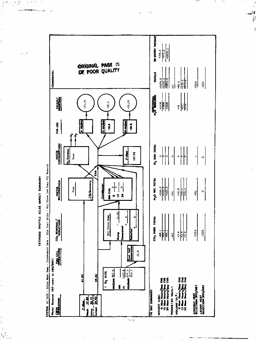
6lE
M
6C D
AY
S -
Uri
ne Wash I)ump
- C
ond
ensa
te S
ave
- Id
le F
uel
C
ells
- W
ol S
iev
e Lo
w D
mp
C02
R
emov
al
Moto
r b
bm
e
(All
rates in
LU
/DA
Y 1
r q
cmra
. N
one
Non
e -0
,
EL-
EM
24
.43
24.u
86
7.6
u -
10 M
Y
Cq
WU
TO
TAL
M2C
4 R
EC I
OT
U
0, Car T
OTA
L -


QQQ 3 Y
EEE EEE


a QQQ
EZE SEE

EX
TE
ND
ED
S
HU
TTLE
KE
LSS
IMP
AC
T
SU
Mh
rAR
"
SV
STE
M
90 DAYS -
All
Kater Reclamation -
Idle Fuel Cell-
- HSC It. H. Control
Cot
R
erov
ai
--.---
- . -.
- ---A
------I
- --
-- &
---
---
-- to
r B
do
mo
IA
II r
ate
s
in L
BS/
DA
Y)
90 M
Y SU
Mm
m
CO
1 S
UB
S
TOTA
L
1 4 G
EN
TOTA
L b-
TO
TALS
R
E-E
WR
Y
WE
lOW

EX
TE
ND
ED
SH
U'l
Lt
LC
iSS
IM
PA
CT
S
UM
MA
R*
C%
RE
MO
VA
L
RE
DU
CII
~
RE
CP
.#~
ION
3
AT
ER
fV
AU
SE
,&
'btift,&
C
ON
UM
PT
ION
IbJh
UL
aL
.I7
5- ,--
RSC Lou
Dub
@
30
DA
Y -
W
c*
ruu
TO
TAL
H*
REC
TO
TAL
o2
GE
N T
OTA
L
WE
IGH
T I
LU
I
0 ManHws/~q EV
A
12
Man )(
run/
Dm
y E
VA
24
Mon n
ou
rs/f
hy
EV
A
PO
WE
R (M
Ww
s 1
VO
LU
ME
( 1
1.3 I
-
TOTA
LS
RE-
ENTR
Y m
mr

QQQ - -


SVHSER 7185

COASTANT FLOW VALVE
AS SEPAIWTOR WI'1'11 VENT
+%- MANUAL VALVE (SHOWN NOKMALLY
OPEN)
ELECTRICAL VALVE WITH MANUAL OVERRIDE (SHOWN NORMALLY
-r CLOSED) w BELLOWS TYPE 'CAIJK
\ HYDROGEN CONTROLLER
3-WAY MANUAL VALVE -I3 DIAPHRAGM TYPE TANK
4-WAY ELECTRICAL VALVE URINAL +- 3-WAY ELECTRICAL
I 2 DET = IODINE DETEC'I'UK
VALVE C 0 2 = CO2 PAR'I'IAL I'RESSURE
(WITH MANUAL P = DIFFEHLNTIAL PRESSUlit. OVERRIDE)
RH = RELATIVE HUXIUI'SY
2-WAY ELECTRICAL CG = COMBUSTIBLE GAS
VALVE F S = FLOW SWITCH
DISPENSER
COLD PLATE
CAPPED SEPTUM
TEMPEHATURE SENSOR
PPESSURE SENSOR
SENSOR
@ CHECK VALVE SWITCII
0 2 = 0 2 PARTIAL PRESSURE
UP = DEW POINT SENSOR
I1 = IODINL GENEUTOR
LT = LIQUID TRAP
NX = SPEED SENSOR
S = SILENCER
W/S = STATIC WATER SEPARATOR
UAC = UREA AMMONIA CONTROL
LS = LIQUID SENSOH
SORB = SORBEN?' CANIS'I'EH
CM = CONDUC'SIVl'I'Y HONITUR
BF = BACTERIA I ' ILTER
CHECK VALVE WITH DOWNSTREAM VENT
PRESSURE REGULATOR (SHOWN OPERATING)
PRESSURE RELIEF VALVE rEr .OR BACK PRESSURE REGULATOR
WATER SEPAAATOR
WITH F I L T E R MANUAL
SCRAPPER P S I D PRESSURE
OR RELIEF VALVE - .. w ( S E N S I N G AC = ACTIVATED CHARCOAL
RAU = REMOTF ACOUISITION MANUAL P R E S S U U UNIT RELIEF VALVE
CAI OX = CATALYTIC OXIDIZER
PUMP
ELECTRICAL HEATER EDC = ELECTlWc'tiEMICAL
DEPOLARI ZED TEMPERATURE CONTROL CONCEN'CWTOR
VALVE HX = HEAT LXCHANGER
AIR/LIQUID HEAT EXCHANGER pH = pH MONITOR
(WITH MF = MULTIFILTER
SENSOR) GS = GAS SEPRATOR
R + RESTRICTOR
BLOWER (WITH SPEED C +
SENSOR) RH H X = RELATIVE HUMIUITY HEAT EXCHANGER
QUICK DISCONNECT WITH CAP
FLOW METER
DEBRIS TWk' SW = SWITCH
COMPONENT INSTALLED WITH A PROBE FOR MAINTMANCE - --3 CAPPED L I N E
COMPONENT INSTALLED WITH DISCONNECTS FOR MAINTENAEiCE EXCHANGER
- - --SUYSYSTEM FUNCTIONAL BOUNDARY


![search.jsp?R=19750015295 2018-05-19T11:28:50+00:00Z · c im--z x'r- laj---0 r.,i_ z co d--- ... nv _jni_irid3_-i.]on 3]11 53_iiw353ci hdihm vivci 1nvoijin_jis _3h10 _0 i_3_.173q (]ijv](https://img.pdfslide.us/doc/110x75/5b3d60937f8b9a213f8dd0cf/r19750015295-2018-05-19t1128500000z-c-im-z-xr-laj-0-ri-z-co-d-.jpg)


![search.jsp?R=19990047476 2020-04-16T21:58:50+00:00Z€¦ · Shapley. A comprehensive presentation of Tchebycheff systems is given in [28]. The output function (1.1) is the sum of](https://img.pdfslide.us/doc/110x75/5ead9b2072611d24940fddc7/r19990047476-2020-04-16t2158500000z-shapley-a-comprehensive-presentation.jpg)