Embed Size (px)
Citation preview

Operation Manual
www.beerinnovations.com
Precautions (safety measures)In order to avoid personal injuries and damaging
the PEGAS CrafTap, please carefully review following safety measures before starting to work with the PEGAS CrafTap:
The power supply unit is only safe when used with electrical networks of 100–240 V, 50/60 Hz, 0.5 A.
If smoke, unusual odors or abnormal sounds start to emerge from the device and/or power unit, immediately disconnect the power unit from the elec-trical outlet. DO NOT use extension cords or any type of unap-
“Proceeding to work with the device may lead p ro v ed wiring system that may expose the electrical to fire, electrical shock or personal injuries.” supply to moisture, condensation, leaks, or any type
After you have disconnected the device from o f l iquid form that may occur in your establishment. the power outlet, please bring the PEGAS CrafTap The proper power outlet should also be close to the nearest approved dealer. to the device and easily accessible.
“We strongly recommend that you call a certified electrician to install an approved power outlet if your device cannot reach a proper power outlet.”
All used containers should conform with your local sanitation requirements for food packaging and be in accordance with your country's laws. Properly washing, rinsing, and sanitizing your
All bottles must also be free of debris, without visual device on a regular basis will greatly reduce cross damages, chips and cracks. Glass bottles should also contamination, lower your maintenance costs, be able to withstand an inner pressure no less than and will guarantee undisrupted operation.0.5 MPa (5 bar).
Compliance with the PEGAS CrafTap operation rules and safety procedures will guarantee undisrupted and safe device operation.
Before releasing the gas into a bottle make sure the protective door of the device is closed.
Do not set the device pressure higher than 0.4 MPa (4 bar).
The power supply unit should only be used with a 100–240 Volt power system.
In case of a malfunction disconnect the device from the power outlet.
Plug the device directly into a proper power outlet.
Only use containers that are within the proper requirements specified by the manufacturer of the PEGAS CrafTap.
Ensure the PEGAS CrafTap is properly cleaned and sanitized after every use.
Remember!Also ensure the protective door is closed before
releasing the gas and/or filling a container.
Contents
1. Scheme 1. Device General View
2. Device Purpose
3. Technical Data
4. Package Contents
5. Device Assembly, Installation and Connection
6. Assembly Instructions
7. Filling Procedure
8. Device Maintenance
9. Troubleshooting
10. Additional Information
11. Acceptance and Sales Information
12. Appendixes. PEGAS CrafTap detailed schemes for service center specialists
Scheme 2. Device Body
Scheme 3. Device Filling Mechanism
Scheme 4. Device Bottle Fixing Mechanism
Scheme 5. Device Electrical Part
......................................................................................................4......................................................................................................4
...........................................................................................................................4...........................................................................................................................4
.............................................................................................................................5.............................................................................................................................5
........................................................................................................................5........................................................................................................................5
...................................................................................5...................................................................................5
..................................................................................................................6..................................................................................................................6
..........................................................................................................................7..........................................................................................................................7
.....................................................................................................................8.....................................................................................................................8
..........................................................................................................................9..........................................................................................................................9
..............................................................................................10..............................................................................................10
........................................11........................................11
..................................................................................................................11..................................................................................................................11
.................................................................................................12.................................................................................................12
..............................................................................................................10..............................................................................................................10
Operation ManualEN 3
........................................................................................13........................................................................................13
......................................................................................................13......................................................................................................13
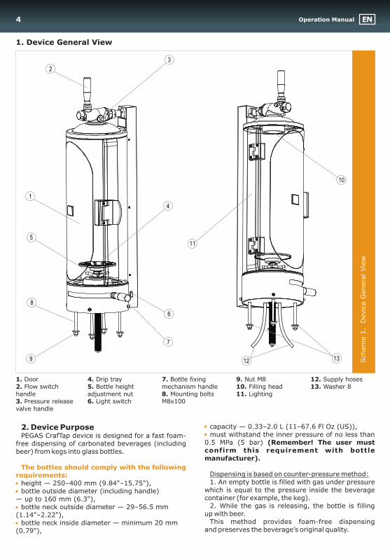
1. Device General View
1. Door 4. Drip tray 7. Bottle fixing 9. Nut Ì8 12. Supply hoses2. Flow switch 5. Bottle height mechanism handle 10. Filling head 13. Washer 8handle adjustment nut 8. Mounting bolts 11. Lighting3. Pressure release 6. Light switch Ì8õ100valve handle
Schem
e 1
. D
evic
e G
enera
l Vie
w
capacity — 0.33–2.0 L (11–67.6 Fl Oz (US)),2. Device Purposemust withstand the inner pressure of no less than PEGAS CrafTap device is designed for a fast foam-
0.5 MPa (5 bar) (Remember! The user must free dispensing of carbonated beverages (including confirm this requirement with bottle beer) from kegs into glass bottles.manufacturer).
Dispensing is based on counter-pressure method:1. An empty bottle is filled with gas under pressure height — 250–400 mm (9.84"–15.75"),
which is equal to the pressure inside the beverage bottle outside diameter (including handle) container (for example, the keg). — up to 160 mm (6.3"),
2. While the gas is releasing, the bottle is filling bottle neck outside diameter — 29–56.5 mm up with beer. (1.14"–2.22"),
This method provides foam-free dispensing bottle neck inside diameter — minimum 20 mm and preserves the beverage’s original quality.(0.79"),
The bottles should comply with the following requirements:
10
11
2
7
5
8
1
4
6
9
3
1312
Operation Manual EN4
3. Technical Data*
* Device appearance, its design, technical data and consumer characteristics may be changed without notice.
* Novosibirskprodmash company is not responsible for the mistakes in the present manual.
4. Package Contents
pcpc
pcpcpcpcpcpc
pcpcpc
pcpcpcpcpcpc
pc
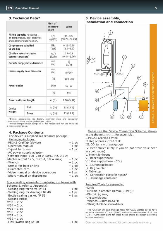
5. Device assembly, installation and connection
Please use the Device Connection Scheme, shown in the above for assembly:
The device is supplied in a separate package:I. PEGAS CrafTap device
Packaging includes:II. Keg or pressurized tank
- PEGAS CrafTap (device) – 1 pcIII. CO tank with gas gauge2- Operation manual – 1 IV. Beer chiller (Only if you do not store your beer - T-joint for hoses – 1 in a cold room)- AC power supply adapterV. T-joint for hoses (network input 100–240 V, 50/60 Hz, 0.5 À; VI. Beer supply hoseadapter output 12 V, 1.25 À, 18 W max) – 1 VII. Gas supply hose (ÑÎ ) 2- Wrench – 1 VIII. Drainage hoses- Stencil for hole drilling – 1 IX. Keg coupler - Guarantee card – 1 X. Table top - Video manual on device operations – 1 XI. Connection parts for hoses*- Short manual on dispensing – 1 XII. Drainage container
Spare sealing elements (numbering conforms with Required Tools for assembly: Scheme 3, refer to Appendix):- Drill;- Sealing ring for valve ¹ 44 – 1 - Drill bit (diameter 10 mm (0.39"));- Sealing ring for drainage ¹ 40 – 1 - Electric jig saw; - Bottle sealing gasket ¹ 53 – 1 - Jig saw blades; - Sealing rings:- Wrench 13 mm (0.51"); ¹33 – 2 - Straight-blade screwdriver.¹34 – 2
¹35 – 1 * The PVC beer, CO and drainage hoses for PEGAS CrafTap device have 2
¹36 – 2 an inside diameter of 7 mm (5/16") and an outside diameter of 12 mm (1/2"). Connection parts for these hoses should be chosen according ¹37 – 1 to these standards.
¹39 – 1 - Flow switch ring ¹ 38 – 1
Layout 1,
Connection scheme and its components may vary.
ÑÎ2 pressure supplied to the keg
ÑÎ2 flow rate (to create counter-pressure)
Net
Gross
Unit of measure-ment
kg/h (lb/h)
kg (lb)
kg (lb)
Value
0.15–0.25 (1.5–2.5)
0.2–0.8 (0.44–1.76)
12 (26.5)
13 (28.7)
Filling capacity /depends on temperature, beer qualities and operator qualification/
L/h (gal/h)
45–120 (10.22–27.24)
Device weight
MPa (bar)
Outside supply hose diametermm (in)
12 (1/2)
Power outlet
(V) ~100–240
(Hz) 50–60
(A) 0.5
Power unit cord length m (ft) 1.80 (5.91)
Layout
1.
Devic
e C
onnection S
chem
e
I
X
XI
VI
IX
IIIVVIII
VII
XII
VIII
mm (in)
7 (5/16)
Inside supply hose diameter
Operation ManualEN 5
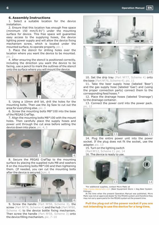
6. Assembly Instructions1. Select a suitable location for the device
installation.2. Ensure that this location has enough free space
(minimum 150 mm/5.91") under the mounting surface for device. This free space will guarantee easy access to the supplying hoses, the device lighting power supply and will allow the device fixing mechanism screw, which is located under the mounted surface, to operate properly.
3. Place the stencil for drilling holes over the location where you want the device to be mounted.
4. After ensuring the stencil is positioned correctly, including the direction you want the device to be facing, use a pencil to mark the outlines of the stencil onto the surface where you will mount the device.
10. Set the drip tray onto the base
11. Take the beer supply hose (labeled ‘Beer’) and the gas supply hose (labeled ‘Gas’) and (using the proper connection parts) connect them to the corresponding feed hoses *
12. Place the drainage hoses (labeled ‘Drainage’) to the drainage container.
5. Using a 10mm drill bit, drill the holes for the 13. Connect the power cord into the power pack.
mounting bolts. Then use the Jig Saw to cut out the area for everything else.
6. Screw the mounting bolts M8*100 into the base of the PEGAS CrafTap.
7. Align the mounting bolts M8*100 with the mount holes. Then carefully place the supply hoses and power unit through the cut area before setting the device down into place.
14. Plug the entire power unit into the power socket. If the plug does not fit the socket, use the adapter.
15. Turn on the lighting switch
16. The device is ready to use.
8. Secure the PEGAS CrafTap to the mounting surface by placing the supplied nuts M8 and washers 8 on the mounting bolts M8*100 and then tightening them. (If needed, you can cut the mounting bolts after the device is secured.)
*For additional supplies, contact Micro Matic at (Beer Equipment Store > Keg Beer System
Fittings).At the time when the present Operation Manual was published, Micro
Matic was not an approved dealer for the PEGAS system and therefore they may not carry spare parts for the PEGAS system at the present time.
9. Screw the handle the screw and the hub
to the device bottle fixing mechanism. Then screw the handle onto the device filling mechanism.
pic. 1
pic. 2
. pic. 11
pic. 12pic. 3
pic. 4, 5
pic. 13
Part . pic. 14
pic. 6
Part
pic. 7–10
(Part ¹77, Scheme 4)(Part ¹76, Scheme 4)
( ¹12, Scheme 1)
(Part ¹58, Scheme 3), ( ¹78, Scheme 4) (Part ¹80,
Scheme 4)(Part ¹58, Scheme 3)
.
http://www.micromatic.com
Pull the plug out of the power socket if you are not intending to use the device for a long time.
3
6
13 14
4
5
7 8
9 10
11 12
1 2
Operation Manual EN6
Filling7. Filling ProcedureI. PreparationBefore dispensing make sure the device is installed 1. Make sure the device is adjusted to the bottle’s properly, secured to its surface, and the connections
height.are sealed without any leaks. (See the previous 2. Turn on the light switch. section for proper installation instructions).3. The flow switch handle should be set in the You should follow the proper procedures, in the
middle (vertical) position. This means that the beer order listed below, while dispensing the beer into the and gas supply channels are closed. bottle.
4. Make sure that the valve handle is firmly Numbering coincides with the PEGAS turned clockwise till the end. This means that the CrafTap device scheme pressure release valve is closed.
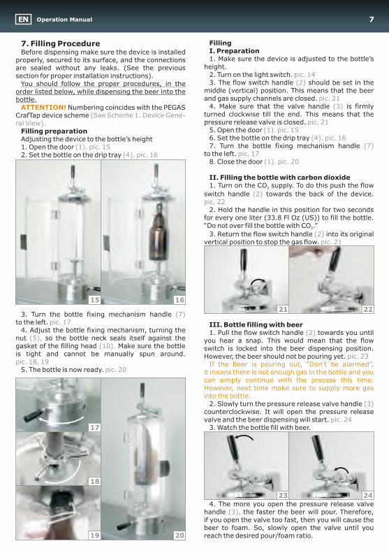
5. Open the door Filling preparation6. Set the bottle on the drip tray Adjusting the device to the bottle’s height 7. Turn the bottle fixing mechanism handle 1. Open the door
to the left. 2. Set the bottle on the drip tray 8. Close the door
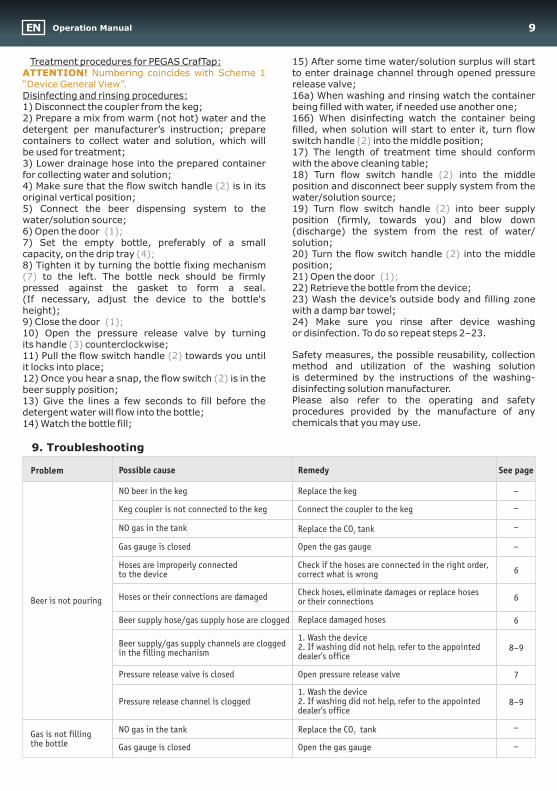
II. Filling the bottle with carbon dioxide 1. Turn on the CO supply. To do this push the flow 2
switch handle towards the back of the device.
2. Hold the handle in this position for two seconds for every one liter (33.8 Fl Oz (US)) to fill the bottle. “Do not over fill the bottle with CO .” 2
3. Return the flow switch handle into its original vertical position to stop the gas flow.
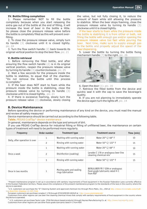
3. Turn the bottle fixing mechanism handle to the left. III. Bottle filling with beer
4. Adjust the bottle fixing mechanism, turning the 1. Pull the flow switch handle towards you until nut so the bottle neck seals itself against the you hear a snap. This would mean that the flow gasket of the filling head Make sure the bottle switch is locked into the beer dispensing position. is tight and cannot be manually spun around. However, the beer should not be pouring yet.
5. The bottle is now ready.
2. Slowly turn the pressure release valve handle counterclockwise. It will open the pressure release valve and the beer dispensing will start.
3. Watch the bottle fill with beer.
4. The more you open the pressure release valve handle the faster the beer will pour. Therefore, if you open the valve too fast, then you will cause the beer to foam. So, slowly open the valve until you reach the desired pour/foam ratio.
ATTENTION!
(2)
(3)
(See Scheme 1. Device Gene-ral View).
(7)
(2)
(2)
(7)
(2)(5),
(10).
(3)
(3),
pic. 14
pic. 21
pic. 21(1). pic. 15
(4). pic. 16
(1). pic. 15pic. 17(4). pic. 16
(1). pic. 20
pic. 22
pic. 21
pic. 17
pic. 23pic. 18, 19
pic.
pic. 24
20If the Beer is pouring out, “Don’t be alarmed”,
it means there is not enough gas in the bottle and you can simply continue with the process this time. However, next time make sure to supply more gas into the bottle.
2221
23 24
15 16
17
18
19 20
Operation ManualEN 7
IV. Bottle filling completion the valve, but not fully closing it, to reduce the 1. Please remember NOT to fill the bottle amount of foam while still allowing the pressure
completely because when you start releasing the to stabilize. When the beer stops foaming, close the extra gas out of the bottle at the end of filling, it will pressure release valve by turning its handle increase the level of beer in the bottle a little. cl o ck w is e until it is closed tightly.So please close the pressure release valve before the bottle is completely filled as this will prevent over-filling.
2. To close the pressure release valve, simply turn its handle clockwise until it is closed tightly.
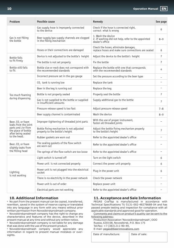
3. Turn the flow switch handle back towards its original vertical position to stop the beer flow. 5. Lower the bottle by turning the bottle fixing
mechanism handle to the right. V. Bottle retrieval1. Before removing the filled bottle, and after
ensuring the flow switch handle is in its original vertical position, reopen the pressure release valve by turning its handle counterclockwise.
2. Wait a few seconds for the pressure inside the bottle to stabilize, to equal that of the chamber. “Do not remove the bottle until this process is complete.”
3. If the beer does NOT start to foam while the 6. Open the door pressure inside the bottle is stabilizing, close the 7. Retrieve the filled bottle from the device and pressure release valve by turning its handle quickly seal it with the cap to save the beverage’s clockwise until it is closed tightly. quality.
4. If there is excessive foaming, slowly turn the 8. If you are not planning to immediately operate pressure release valve clockwise, slowly closing the device again turn the lights off.
(3)
(3)
(2)
(7)
(2)
(3)
(3)
(3)
pic. 24
pic. 21pic. 26
pic. 25
(1). pic. 16
pic. 21
pic. 14
If the beer starts to foam while the pressure inside the bottle is stabilizing it is from either or both, not filling the bottle with enough gas and/or opening the pressure release valve too fast while pouring the beer. Next time, make sure to supply enough gas to the bottle and properly adjust the speed of the beer dispensing.
8. Device MaintenanceBefore operating the device or performing maintenance of any kind on the device, you must read the manual
and review all safely measures! Device maintenance should be carried out according to the following table.
In general, maintenance depends on the type and amount of dirt.If you use PEGAS CrafTap device for industrial filling or filling of unfiltered beer, the maintenance on certain
types of treatment will need to be performed more regularly.
* Present maintenance program is set up in accordance with sanitary requirements of food equipment in the Russian Federation Laws currently effective in the Russian Federation territory. Please assure the compliance of the present maintenance program to the standards of the laws in the country where the device is operated.
U.S. customers can purchase the “D” Cleaning System and approved chemical mix through Micro Matic, Inc., USA at
European customers can purchase Lerades C 178 through STOCKMEIER GROUP at Customers from other regions can use beer line cleaning chemical mixes that comply with sanitary requirements of food equipment in the country where
the device is operated.
U.S. customers can purchase Taylor Lube (FDA Petroleum based products) through Haynes Manufacturing Co. at Customers from other regions can use other food-grade lubricants rated H-1 from NSF.
Table. PEGAS CrafTap* device maintenance
1
2
http://www.micromatic.com/draft-keg-beer/line-cleaning-cid-425.html.
http://www.stockmeier.de/
http://www.haynesmfg.com/.
Daily, after operation is overWater 20 Ñ/ 68° F° 10
15
Moving parts and sealing rings lubrication
Washing with running water
Lerades C 178 or analogous beer line 1cleaning chemical mixOnce a week
10
15
15
BERULUBER FR 7 GSN or analogous food-grade lubricants rated H-1
2from NSF
Frequency Treatment source Time (min)Treatment typeOrder number
Water 50 Ñ/ 122° F°
–Once in two months
1
2
2
1
3
1
25 26
Washing with running water
Rinsing with running water
Disinfection (soaking)
Rinsing with running water
Water 20 Ñ/ 68° F°
Water 50 Ñ/ 122° F°
Operation Manual EN8
Treatment procedures for PEGAS CrafTap: 15) After some time water/solution surplus will start to enter drainage channel through opened pressure release valve;
Disinfecting and rinsing procedures: 16à) When washing and rinsing watch the container 1) Disconnect the coupler from the keg; being filled with water, if needed use another one;2) Prepare a mix from warm (not hot) water and the 16á) When disinfecting watch the container being detergent per manufacturer’s instruction; prepare filled, when solution will start to enter it, turn flow containers to collect water and solution, which will switch handle into the middle positionbe used for treatment; 17) The length of treatment time should conform 3) Lower drainage hose into the prepared container with the above cleaning table;for collecting water and solution; 18) Turn flow switch handle into the middle 4) Make sure that the flow switch handle is in its position and disconnect beer supply system from the original vertical position; water/solution source;5) Connect the beer dispensing system to the 19) Turn flow switch handle into beer supply water/solution source; position (firmly, towards you) and blow down 6) Open the door (discharge) the system from the rest of water/ 7) Set the empty bottle, preferably of a small solution;capacity, on the drip tray 20) Turn the flow switch handle into the middle 8) Tighten it by turning the bottle fixing mechanism position;
to the left. The bottle neck should be firmly 21) Open the door pressed against the gasket to form a seal. 22 ) Re tri ev e t he bo ttl e f ro m the device;(If necessary, adjust the device to the bottle's 23) Wash the device’s outside body and filling zone height); with a damp bar towel;9) Close the door 24) Make sure you rinse after device washing 10) Open the pressure release valve by turning o r di sinfection. To do so repeat steps 2–23.its handle counterclockwise;
Safety measures, the possible reusability, collection 11) Pull the flow switch handle towards you until method and utilization of the washing solution it locks into place;is determined by the instructions of the washing-12) Once you hear a snap, the flow switch is in the disinfecting solution manufacturer.beer supply position;Please also refer to the operating and safety 13) Give the lines a few seconds to fill before the procedures provided by the manufacture of any detergent water will flow into the bottle;chemicals that you may use.14) Watch the bottle fill;
ATTENTION! Numbering coincides with Scheme 1 “Device General View”.
(2)
(2)(2)
(2)
(2)
(7)
(3)(2)
(2)
(1);
(4);
(1);
(1);
;
9. Troubleshooting
Possible cause Remedy
NO beer in the keg
Keg coupler is not connected to the keg
Replace the keg
Connect the coupler to the keg
NO gas in the tank Replace the CO tank2
Gas gauge is closed Open the gas gauge
Hoses or their connections are damaged Check hoses, eliminate damages or replace hoses or their connections
Beer supply hose/gas supply hose are clogged Replace damaged hoses
Beer is not pouring
Problem
Hoses are improperly connected to the device
Check if the hoses are connected in the right order, correct what is wrong
1. Wash the device2. If washing did not help, refer to the appointed dealer’s office
Beer supply/gas supply channels are clogged in the filling mechanism
Pressure release valve is closed Open pressure release valve
1. Wash the device2. If washing did not help, refer to the appointed dealer’s office
Pressure release channel is clogged
See page
–
–
–
–
6
6
6
8–9
7
8–9
NO gas in the tank Replace the CO tank2
Gas gauge is closed Open the gas gauge
–
–
Gas is not filling the bottle
Operation ManualEN 9
Hoses or their connections are damaged
Bottle size or neck does not correspond with the recommended standards
Replace the bottle with one that corresponds with the recommended standards
Incorrect pressure set in the gas gauge
CO tank is running low2 Replace the tank
Beer in the keg is running out Replace the keg
Pressure release speed is too fast Adjust pressure release speed
Beer supply channel is contaminated Wash the device
Rubber gaskets are worn out
Gas is not filling the bottle
Bottle still fails to fit
Too much foaming during dispensing
Beer, CO or foam 2
leaks from the joint parts and /or from the place of bottle after being sealed to the head.
Gas supply hose is improperly connected to the device
Check if the hose is connected right, correct what is wrong
Improper tightening of threaded joint partsWith the use of proper instrument, fasten all threaded joints
1. Wash the device2. If washing did not help, refer to the appointed dealer’s office
Beer supply/gas supply channels are clogged in the filling mechanism
Device is not adjusted to the bottle’s height Adjust the device to the bottle’s heightBottle fails to fit firmly
The bottle is not set properly Fix the bottle
Bottle is not properly sealed Properly seal the bottle
Gas is not supplied to the bottle or supplied in insufficient amounts
Supply additional gas to the bottle
Bottle fixing mechanism is not adjusted properly to the bottle’s height
Adjust the bottle fixing mechanism properly to the bottle’s height
6
8–9
6
7
7
4
–
–
–
7
7
7–8
8–9
–
7
–
Refer to the appointed dealer’s officeThe springs of the flow switch are too loose
Power unit is not connected properly
Electrical parts are not working
Lighting is not working
Light switch is turned off Turn on the light switch
Power unit is not plugged into the electrical socket
Plug in the power unit
There is no electricity in the power network Check the power network
Power unit is out of order Replace power unit
The sealing gaskets of the flow switch are worn out
Beer, CO or foam 2
slightly leaks from the filling head
Refer to the appointed dealer’s office –
–
6
6
6
–
–
–
Possible cause RemedyProblem See page
Check the hoses, eliminate damages, replace hoses and make sure connections are sealed
Set the pressure according to the beer type
Refer to the appointed dealer’s office
Connect the power unit properly
Refer to the appointed dealer’s office
10. Additional Information 11. Acceptance and Sale InformationNo part from the present manual can be copied, transferred, PEGAS CrafTap is manufactured in accordance with
rewritten, saved in the system of reserve coping or translated Technical Specifications ÒU and has into any language in any form with any means without prior passed presale testing and inspection for compliance with all written permission from Novosibirskprodmash company. applicable standards and approved good for operation.
Novosibirskprodmash company has the right to change any Comments and claims on product’s quality can be sent to the characteristics and features of the device, described in the following address:present manual at any time and without any written notice. Production Association ‘Novosibirskprodmash’, OOO
Novosibirskprodmash company is not liable for any damage Russia, 630108, Novosibirsk, P.O. Box 175 that was done with the use of the present product. Tel/fax: +7 (383) 211-90-49,
Novosibirskprodmash company would appreciate any E-mail: [email protected] in regard to present manual mistakes or over-sights.
5131-002-48278688-04
Date of manufacture: Date of sale:
Operation Manual EN10
Schem
e 2
. P
EG
AS C
rafT
ap:
Devic
e B
ody
1
2
3
5
6
7
8
9
9 12
11 10
4
17
18
14
15
16
13
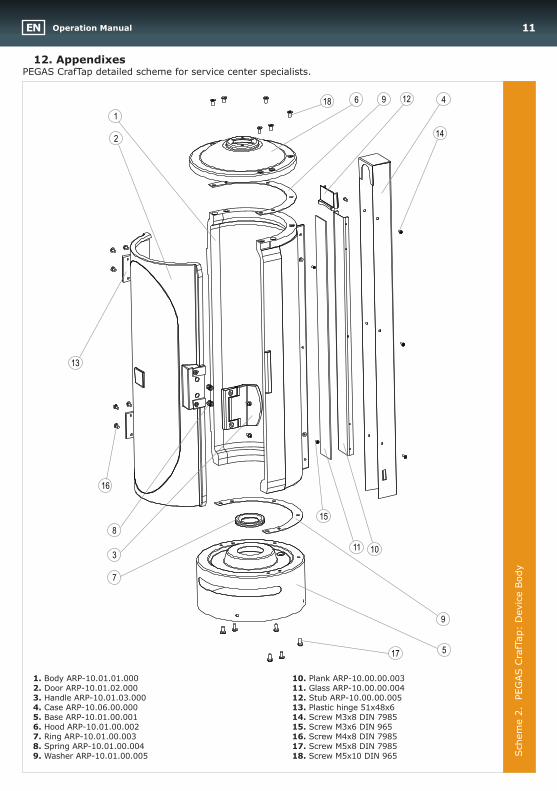
12. Appendixes PEGAS CrafTap detailed scheme for service center specialists.
1. Body ÀRP-10.01.01.000 10. Plank ÀRP-10.00.00.0032. Door ÀRP-10.01.02.000 11. Glass ÀRP-10.00.00.0043. Handle ARP-10.01.03.000 12. Stub ÀRP-10.00.00.0054. Case ÀRP-10.06.00.000 13. Plastic hinge 51õ48õ65. Base ÀRP-10.01.00.001 14. Screw Ì3õ8 DIN 79856. Hood ÀRP-10.01.00.002 15. Screw Ì3õ6 DIN 9657. Ring ÀRP-10.01.00.003 16. Screw Ì4õ8 DIN 7985 8. Spring ÀRP-10.01.00.004 17. Screw Ì5õ8 DIN 79859. Washer ÀRP-10.01.00.005 18. Screw Ì5õ10 DIN 965
Operation ManualEN 11
Schem
e 3
. PEG
AS C
rafT
ap:
Filling M
echanis
m
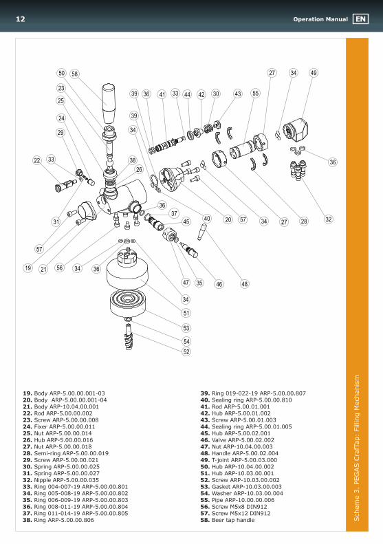
19. Body ÀRP-5.00.00.001-03 39. Ring 019-022-19 ÀRP-5.00.00.80720. Body ÀRP-5.00.00.001-04 40. Sealing ring ÀRP-5.00.00.81021. Body ÀRP-10.04.00.001 41. Rod ÀRP-5.00.01.00122. Rod ÀRP-5.00.00.002 42. Hub ÀRP-5.00.01.00223. Screw ÀRP-5.00.00.008 43. Screw ÀRP-5.00.01.00324. Fixer ÀRP-5.00.00.011 44. Sealing ring ÀRP-5.00.01.00525. Nut ÀRP-5.00.00.014 45. Hub ÀRP-5.00.02.00126. Hub ÀRP-5.00.00.016 46. Valve ÀRP-5.00.02.00227. Nut ÀRP-5.00.00.018 47. Nut ÀRP-10.04.00.00328. Semi-ring ÀRP-5.00.00.019 48. Handle ÀRP-5.00.02.00429. Screw ÀRP-5.00.00.021 49. T-joint ARP-5.00.03.00030. Spring ÀRP-5.00.00.025 50. Hub ÀRP-10.04.00.00231. Spring ÀRP-5.00.00.027 51. Hub ÀRP-10.03.00.00132. Nipple ÀRP-5.00.00.035 52. Screw ÀRP-10.03.00.00233. Ring 004-007-19 ÀRP-5.00.00.801 53. Gasket ÀRP-10.03.00.00334. Ring 005-008-19 ÀRP-5.00.00.802 54. Washer ÀRP-10.03.00.00435. Ring 006-009-19 ÀRP-5.00.00.803 55. Pipe ÀRP-10.00.00.00636. Ring 008-011-19 ÀRP-5.00.00.804 56. Screw Ì5õ8 DIN91237. Ring 011-014-19 ÀRP-5.00.00.805 57. Screw Ì5õ12 DIN91238. Ring ÀRP-5.00.00.806 58. Beer tap handle
19
20
21
22
23
24
25
26
27
27
28
29
30
31 32
33
33
34
34
34
34
34
35
39 36
36
36
36
37
38
39
40
41 42 4344
45
4647 48
4950
51
53
52
54
56
57
57
58
55
Operation Manual EN12
Schem
e 4
. PEG
AS C
rafT
ap:
Bott
le F
ixin
g M
echanis
m
61
62
63
64
65
66
67
68
69
70
71
72
73
7475
34
78
79
80
58
81
57
57
57
57
82
82
83
84
85
76
77
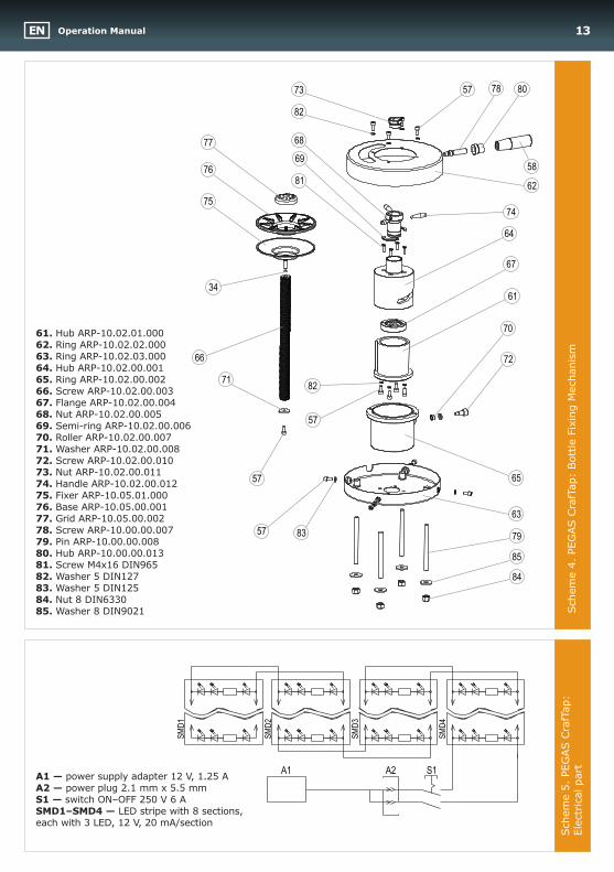
61. Hub ÀRP-10.02.01.00062. Ring ÀRP-10.02.02.00063. Ring ÀRP-10.02.03.00064. Hub ÀRP-10.02.00.00165. Ring ÀRP-10.02.00.00266. Screw ÀRP-10.02.00.00367. Flange ÀRP-10.02.00.00468. Nut ÀRP-10.02.00.00569. Semi-ring ÀRP-10.02.00.00670. Roller ÀRP-10.02.00.00771. Washer ÀRP-10.02.00.00872. Screw ÀRP-10.02.00.01073. Nut ÀRP-10.02.00.01174. Handle ÀRP-10.02.00.01275. Fixer ÀRP-10.05.01.00076. Base ÀRP-10.05.00.00177. Grid ÀRP-10.05.00.00278. Screw ÀRP-10.00.00.00779. Pin ÀRP-10.00.00.00880. Hub ÀRP-10.00.00.01381. Screw Ì4õ16 DIN96582. Washer 5 DIN127 83. Washer 5 DIN12584. Nut 8 DIN6330 85. Washer 8 DIN9021
À1 À2 S1
SM
D1
SM
D2
SM
D3
SM
D4
A1 — power supply adapter 12 V, 1.25 À A2 — power plug 2.1 mm x 5.5 mmS1 — switch ON–OFF 250 V 6 ÀSMD1–SMD4 — LED stripe with 8 sections, each with 3 LED, 12 V, 20 mÀ/section
Schem
e 5
. PEG
AS C
rafT
ap:
Ele
ctr
ical part
Operation ManualEN 13
Operation Manual EN14
Technical Maintenance List
Date Type of technical maintenance Performer Signature