Embed Size (px)
Citation preview

- Boundary Conditions - Boundary Conditions
Boundary ConditionsBoundary ConditionsBoundary Conditions
This chapter includes material from the book “Practical FiniThis chapter includes material from the book “Practical Fini
additional material added by Matthias Goelke.additional material added by Matthias Goelke.
Boundary ConditionsBoundary ConditionsBoundary Conditions
The boundary condition is the application of a force and/or constraint.The boundary condition is the application of a force and/or constraint.
what are called load collectors. Load collectors may be created using the Twhat are called load collectors. Load collectors may be created using the
(Create > Load Collector).(Create > Load Collector).
Quite often (especially at the beginning) a load collector is neededQuite often (especially at the beginning) a load collector is needed
and a second one is needed for the forces and/or pressures. Keepand a second one is needed for the forces and/or pressures. Keep
with respect to dof 1, or nodes with constraints dof123, etc. in awith respect to dof 1, or nodes with constraints dof123, etc. in a
They are stored within a single load collector regardless of their orientationThey are stored within a single load collector regardless of their orientation
In the following you will learn some basic principles about the way In the following you will learn some basic principles about the way
1. Concentrated load (at a point or single node)1. Concentrated load (at a point or single node)
Applying forces to single nodes may cause irritating effects, especiallyApplying forces to single nodes may cause irritating effects, especially
concentrated loads (i.e. forces on a single node) impose high stressconcentrated loads (i.e. forces on a single node) impose high stress
applied to an infinitesimal small area) one needs to ask whetherapplied to an infinitesimal small area) one needs to ask whether
real-life loading scenario is represented in the model?real-life loading scenario is represented in the model?
Therefore, forces are commonly applied as distributed loads, namelyTherefore, forces are commonly applied as distributed loads, namely
11
Conditions And Loads -Conditions And Loads -
Conditions And LoadsConditions And LoadsConditions And Loads
Finite Element Analysis”. It also has been reviewed and has Finite Element Analysis”. It also has been reviewed and has
constraint. In HyperMesh, boundary conditions are stored withinconstraint. In HyperMesh, boundary conditions are stored within
ed using the right click context menu in the Model Browsered using the right click context menu in the Model Browser
needed for the constraints (also called SPC – Single Point Constraints)needed for the constraints (also called SPC – Single Point Constraints)
eep in mind, you can place any constraints (e.g. nodes constraint)eep in mind, you can place any constraints (e.g. nodes constraint)
single load collector. The same rule applies for forces/pressures.single load collector. The same rule applies for forces/pressures.
orientation and magnitude.orientation and magnitude.
y forces may be applied to a structure.y forces may be applied to a structure.
especially while looking at the stresses in this area. Typicallyespecially while looking at the stresses in this area. Typically
stress gradients. Even though the high stresses are correct (i.e. forcestress gradients. Even though the high stresses are correct (i.e. force
ther this kind of loading is reasonable at all? In other words, whichther this kind of loading is reasonable at all? In other words, which
namely line loads, and surface loads which are “closer” to reality.namely line loads, and surface loads which are “closer” to reality.

- Boundary Conditions - Boundary Conditions
2. Force On Line Or Edge2. Force On Line Or Edge
In the above figure, a plate subjected to 10.000 N. The force is eqIn the above figure, a plate subjected to 10.000 N. The force is eq
forces at the corner will act only on ½ of the element edge.forces at the corner will act only on ½ of the element edge.
The figure below is a displacement contour plot. Note the red “hotspThe figure below is a displacement contour plot. Note the red “hotsp
maximus are imposed by boundary effects (i.e. the forces applied tmaximus are imposed by boundary effects (i.e. the forces applied t
we applied a constant magnitude along the plate’s edge.we applied a constant magnitude along the plate’s edge.
In the example below, the plate is also subjected to 10.000 N. ThisIn the example below, the plate is also subjected to 10.000 N. This
other applied forces.other applied forces.
22
Conditions And Loads -Conditions And Loads -
qually applied to all (11) nodes at the model edge. Note that thequally applied to all (11) nodes at the model edge. Note that the
otspots” located in the corners of the plate. The local displacementotspots” located in the corners of the plate. The local displacement
to the corner nodes act only on ½ of the element edge), howeverto the corner nodes act only on ½ of the element edge), however
This time the forces at the corners are just ½ the magnitude of theThis time the forces at the corners are just ½ the magnitude of the

- Boundary Conditions - Boundary Conditions
Quite apparently, the displacements are now more evenly distribuQuite apparently, the displacements are now more evenly distribu
3. Traction (Or “Oblique” Pressure)3. Traction (Or “Oblique” Pressure)
Traction is a force acting on an area in any direction other than the
pressure.pressure.
4. Distributed Load (Force Varying As Equation)4. Distributed Load (Force Varying As Equation)
33
Conditions And Loads -Conditions And Loads -
distributed (see figure below).distributed (see figure below).
ther than the normal direction. A force acting normal to an area is known as

- Boundary Conditions - Boundary Conditions
How to apply a force with “variable” magnitude?How to apply a force with “variable” magnitude?
Distributed loads (varying with respects to the coordinates of theDistributed loads (varying with respects to the coordinates of the
the displayed example, the magnitude of the applied forces variesthe displayed example, the magnitude of the applied forces varies
negative z-direction and increases along positive y-direction by a fnegative z-direction and increases along positive y-direction by a f
5. Pressure And Vacuum5. Pressure And Vacuum
In the image above, a distributed load (pressure) is shown. TheIn the image above, a distributed load (pressure) is shown. The
upper corner.upper corner.
How to apply a pressure with “variable” magnitude?How to apply a pressure with “variable” magnitude?
In the example above, the magnitude of the applied pressure depends on the xIn the example above, the magnitude of the applied pressure depends on the x
6. Hydrostatic Pressure6. Hydrostatic Pressure
Civil engineering applications: Dam design. Mechanical engineering applications: Civil engineering applications: Dam design. Mechanical engineering applications:
Hydrostatic pressure is zero at the top surface of the liquid and isHydrostatic pressure is zero at the top surface of the liquid and is
as shown in the following figure:as shown in the following figure:
The hydrostatic pressure is applied taking into account the element The hydrostatic pressure is applied taking into account the element
44
Conditions And Loads -Conditions And Loads -
the nodes or elements) can be applied by means of an equation. Inthe nodes or elements) can be applied by means of an equation. In
varies with respect to the nodal y-coordinate (i.e. the force is acting invaries with respect to the nodal y-coordinate (i.e. the force is acting in
factor of 10 respectively).factor of 10 respectively).
origin of the plate is located at the highlighted node in the leftorigin of the plate is located at the highlighted node in the left
the applied pressure depends on the x- and z-direction of the elements centroid.the applied pressure depends on the x- and z-direction of the elements centroid.
Mechanical engineering applications: Vessels / tanks containing liquid.Mechanical engineering applications: Vessels / tanks containing liquid.
is maximum (= ρ* g * h) at the bottom surface. It varies linearlyis maximum (= ρ* g * h) at the bottom surface. It varies linearly
element centroids location (vertical position, h).element centroids location (vertical position, h).

- Boundary Conditions - Boundary Conditions
7. Bending Moments7. Bending Moments
The convention for representing a force is a single arrow (g ), poinThe convention for representing a force is a single arrow (g ), poin
by a double arrow, where the direction of the moment is decided by by a double arrow, where the direction of the moment is decided by
The nodes along the plate’s edge are subjected to moments. As aThe nodes along the plate’s edge are subjected to moments. As a
y-axis (dof 5).y-axis (dof 5).
In the image above, the plate is subjected to moments along itsIn the image above, the plate is subjected to moments along its
initial model is displayed as wire frame.initial model is displayed as wire frame.
The moment applied to the nodes in the figure above can also beThe moment applied to the nodes in the figure above can also be
are then subjected to corresponding forces. In this example, the RBEare then subjected to corresponding forces. In this example, the RBE
acting in x-direction as shown in the figures below.acting in x-direction as shown in the figures below.
55
Conditions And Loads -Conditions And Loads -
pointed towards the direction of the force . A moment is representedpointed towards the direction of the force . A moment is represented
by the right hand rule.by the right hand rule.
a consequence, the nodes will tend to rotate with respect to thea consequence, the nodes will tend to rotate with respect to the
edge on the right. The displacements are scaled by 100 and theedge on the right. The displacements are scaled by 100 and the
be modeled by adding rigid elements (RBE2) to each node whichbe modeled by adding rigid elements (RBE2) to each node which
RBE2 would be oriented in the z-direction and subjected to a forceRBE2 would be oriented in the z-direction and subjected to a force

- Boundary Conditions - Boundary Conditions
While postprocessing the results make sure that the RBE2 resultsWhile postprocessing the results make sure that the RBE2 results
displacements of the shell elements).displacements of the shell elements).
8. Torque8. Torque
What is torque? Are torque and bending moments different?What is torque? Are torque and bending moments different?
Torque is a bending moment applied parallel to the axis of a shaft (MTorque is a bending moment applied parallel to the axis of a shaft (M
Torque or M causes shear stresses and angular deformation, whileTorque or M causes shear stresses and angular deformation, whilex
stress and longitudinal deformation.stress and longitudinal deformation.
How to decide the direction of torque (clockwise or anticlockwise)How to decide the direction of torque (clockwise or anticlockwise)
66
Conditions And Loads -Conditions And Loads -
results (i.e. nodal position) are not postprocessed (just display the results (i.e. nodal position) are not postprocessed (just display the
t (M ).x
t (M ).x
while the effect of the other two moments (M , M ) is the normalwhile the effect of the other two moments (M , M ) is the normaly z
anticlockwise)anticlockwise)

- Boundary Conditions - Boundary Conditions
It is based on the right hand rule. Point the thumb of your rightIt is based on the right hand rule. Point the thumb of your right
indicate the direction of torque.
TorqueTorque
yy
xxz
How to apply torque for solid elements (brick /tetra)How to apply torque for solid elements (brick /tetra)
As solid elements have no rotational stiffness at the grid points (only 3 translational As solid elements have no rotational stiffness at the grid points (only 3 translational
and moments to the grid points of solid elements directly.and moments to the grid points of solid elements directly.
The correct way to apply a moment to a solid model is to use an The correct way to apply a moment to a solid model is to use an
distributes an applied moment into the solid element model as fodistributes an applied moment into the solid element model as fo
Rigid Element Connection RBE2Rigid Element Connection RBE2
A center node is connected to the outer edge nodes using a rigid element A center node is connected to the outer edge nodes using a rigid element
Alternatively, you may use an RBE3 elements insteadAlternatively, you may use an RBE3 elements instead
Select the nodes at the outer contour of the shaft as independent Select the nodes at the outer contour of the shaft as independent
automatically. It is pretty easy.automatically. It is pretty easy.
However, care needs to be taken with respect to the dof’s beingHowever, care needs to be taken with respect to the dof’s being
degrees of freedom only (dof 123). The dependent node also allodegrees of freedom only (dof 123). The dependent node also allo
77
Conditions And Loads -Conditions And Loads -
right hand towards the arrow direction. The direction of your fingersright hand towards the arrow direction. The direction of your fingers
ConstraintsConstraints
(clamped, 123456=0)(clamped, 123456=0)
(only 3 translational dofs), a common mistake is to apply torques (only 3 translational dofs), a common mistake is to apply torques
an RBE2 or RBE3 rigid-body element. The rigid-body elementan RBE2 or RBE3 rigid-body element. The rigid-body element
orces.orces.
element (RBE2). The torque is then applied at the center node.element (RBE2). The torque is then applied at the center node.
independent nodes. The dependent node may then be determinedindependent nodes. The dependent node may then be determined
being referenced. The node of the solid shaft possess translationalbeing referenced. The node of the solid shaft possess translational
ows for rotational displacements (dof 123456). If the rotationalows for rotational displacements (dof 123456). If the rotational

- Boundary Conditions - Boundary Conditions
dof (in this example dof 5; rotation y-axis) of the dependent nodedof (in this example dof 5; rotation y-axis) of the dependent node
independent nodes.
Shell Element CoatingShell Element Coating
On the brick/tetra element outer face additional quad/tria (2D) elementsOn the brick/tetra element outer face additional quad/tria (2D) elements
these shell element should be negligible (so that it would not athese shell element should be negligible (so that it would not a
nodes (moment per node = total moment / no. of nodes on the face)nodes (moment per node = total moment / no. of nodes on the face)
The shell element coating can be easily created within HyperMesh.The shell element coating can be easily created within HyperMesh.
though the toolbar icon which is displayed using View > Toolbathough the toolbar icon which is displayed using View > Toolba
The faces (nothing more than 2D plot elements) are automaticallyThe faces (nothing more than 2D plot elements) are automatically
you need to do is treat these elements as regular elements (i.e. renameyou need to do is treat these elements as regular elements (i.e. rename
88
Conditions And Loads -Conditions And Loads -
node is not “activated”, the moment will not be transferred to thenode is not “activated”, the moment will not be transferred to the
elements coating the solid elements are created. The thickness ofelements coating the solid elements are created. The thickness of
affect the results). Moment could now be applied on all the faceaffect the results). Moment could now be applied on all the face
ace).ace).
HyperMesh. Create faces using the Faces panel. This panel can be accessed HyperMesh. Create faces using the Faces panel. This panel can be accessed
oolbars > Checks.oolbars > Checks.
omatically created and stored in a component collector named ^faces. Allomatically created and stored in a component collector named ^faces. All
rename the component collector, assign materials and properties).rename the component collector, assign materials and properties).

- Boundary Conditions - Boundary Conditions
In the figure above, the elements of the shaft are displayed by meansIn the figure above, the elements of the shaft are displayed by means
are the hexahedral elements (3D), and the red elements are the 2Dare the hexahedral elements (3D), and the red elements are the 2D
9. Temperature Loading9. Temperature Loading
Suppose a metallic ruler is lying on the ground freely as shown inSuppose a metallic ruler is lying on the ground freely as shown in
50 degrees, would there be any stress in the ruler due to temperature?50 degrees, would there be any stress in the ruler due to temperature?
There will be no stress in the ruler. It will just expand (thermal strain)There will be no stress in the ruler. It will just expand (thermal strain)
there is a hindrance or resistance to deformation. Consider anothere is a hindrance or resistance to deformation. Consider ano
rigid wall (non conductive material). Now if the temperature is increased,rigid wall (non conductive material). Now if the temperature is increased,
below.below.
For thermal stress calculations, the input data needed is the teFor thermal stress calculations, the input data needed is the te
conductivity, and the coefficient of linear thermal expansion.conductivity, and the coefficient of linear thermal expansion.
99
Conditions And Loads -Conditions And Loads -
means of the shrink element command, . The orange elementsmeans of the shrink element command, . The orange elements
are the 2D elements placed on the free faces of the 3D elements.are the 2D elements placed on the free faces of the 3D elements.
the figure below. If the temperature of the room is increased tothe figure below. If the temperature of the room is increased to
perature?perature?
strain) due to the higher temperature. Stress is caused only whenstrain) due to the higher temperature. Stress is caused only when
other case, this time one end of the metallic object is fixed on aother case, this time one end of the metallic object is fixed on a
increased, it will produce thermal stress (at the fixed end) as shownincreased, it will produce thermal stress (at the fixed end) as shown
emperature value on nodes, the ambient temperature, thermalemperature value on nodes, the ambient temperature, thermal

- Boundary Conditions - Boundary Conditions
10. Gravity Loading10. Gravity Loading
Specify direction of gravity and material density.Specify direction of gravity and material density.
A load collector with the card image GRAV is needed (here the FEMA load collector with the card image GRAV is needed (here the FEM
Please keep your unit system in mind.Please keep your unit system in mind.
11. Centrifugal Load11. Centrifugal Load
The user has to specify the angular velocity, axis of rotation, and matThe user has to specify the angular velocity, axis of rotation, and mat
The RFORCE Card Image defines a static loading condition due to The RFORCE Card Image defines a static loading condition due to
12. ‘G’ Values (General Rules) For Full Vehicle Analysis12. ‘G’ Values (General Rules) For Full Vehicle Analysis
• Vertical acceleration (Impact due to wheel passing over speed • Vertical acceleration (Impact due to wheel passing over speed
• Lateral acceleration (Cornering force, acts when vehicle • Lateral acceleration (Cornering force, acts when vehicle
• Axial acceleration (Braking or sudden acceleration): 0.5• Axial acceleration (Braking or sudden acceleration): 0.5
1010
Conditions And Loads -Conditions And Loads -
FEM Solver OptiStruct is chosen as the User Profile in HyperMesh).FEM Solver OptiStruct is chosen as the User Profile in HyperMesh).
material density as input data.material density as input data.
o a centrifugal force field.o a centrifugal force field.
er speed braker or pot holes): 3ger speed braker or pot holes): 3g
ehicle takes a turn on curves): 0.5 to 1 gehicle takes a turn on curves): 0.5 to 1 g
or sudden acceleration): 0.5 to 1 gor sudden acceleration): 0.5 to 1 g
1010

- Boundary Conditions - Boundary Conditions
13. One Wheel In Ditch13. One Wheel In Ditch
The FE model should include all of the components (non criticalThe FE model should include all of the components (non critical
mass of the vehicle and FE model mass, as well as actual wheel vmass of the vehicle and FE model mass, as well as actual wheel v
While applying a constraint, the vertical dof of the wheel, which isWhile applying a constraint, the vertical dof of the wheel, which is
constraints should be applied on the other wheels so as to avoidconstraints should be applied on the other wheels so as to avoid
magnitude = 3*9810 mm/sec2magnitude = 3*9810 mm/sec2
3 g3 g
Another simple but approximate approach (since most of the timeAnother simple but approximate approach (since most of the time
sufficient time for a detailed FE model) is to apply 3 times the reactionsufficient time for a detailed FE model) is to apply 3 times the reaction
reaction (as per test data) is 1000 N. Therefore, apply 3 * 1000reaction (as per test data) is 1000 N. Therefore, apply 3 * 1000
the other three wheels enough to avoid rigid body motion. Thisthe other three wheels enough to avoid rigid body motion. This
designs).designs).
14. Two Wheels In Ditch14. Two Wheels In Ditch
Same as discussed above, except now instead of one wheel, twoSame as discussed above, except now instead of one wheel, two
while two wheels in the ditch produces a bending load.while two wheels in the ditch produces a bending load.
15. Braking15. Braking
Linear acceleration (or gravity) along the axial direction (opposite Linear acceleration (or gravity) along the axial direction (opposite
0.5 to 1
1111
Conditions And Loads -Conditions And Loads -
components could be represented by a concentrated mass). Thecomponents could be represented by a concentrated mass). The
vehicle reactions and FE model wheel reactions, should match.vehicle reactions and FE model wheel reactions, should match.
is in considered in the ditch, should be released. The appropriateis in considered in the ditch, should be released. The appropriate
rigid body motion. Specify the gravity direction as downward andrigid body motion. Specify the gravity direction as downward and
time either we do not have all the CAD data for the entire vehicle ortime either we do not have all the CAD data for the entire vehicle or
reaction force on the wheel which is in the ditch. Suppose the wheelreaction force on the wheel which is in the ditch. Suppose the wheel
or 3000 N force in the vertically upward direction and constraintor 3000 N force in the vertically upward direction and constraint
approach works well for relative design (for comparison of twoapproach works well for relative design (for comparison of two
o wheels are in the ditch. One wheel in the ditch causes twisting,o wheels are in the ditch. One wheel in the ditch causes twisting,
3 g3 g
3 g3 g
e to vehicle motion) = 0.5 to 1 g.e to vehicle motion) = 0.5 to 1 g.
o 1 g
1111

- Boundary Conditions - Boundary Conditions
16. Cornering16. Cornering
Linear acceleration along the lateral direction = 0.5 to 1 g.Linear acceleration along the lateral direction = 0.5 to 1 g.
0.50.5
How To Apply ConstraintsHow To Apply Constraints
A beginner may find it difficult to apply boundary conditions, andA beginner may find it difficult to apply boundary conditions, and
faces the following two basic questions:faces the following two basic questions:
i) For a single component analysis, should forces and constraintsi) For a single component analysis, should forces and constraints
body diagram) or should the surrounding components also be body diagram) or should the surrounding components also be
ii) At what location and how many dof should be constrained.ii) At what location and how many dof should be constrained.
Constraints (supports) are used to restrain structures against relatiConstraints (supports) are used to restrain structures against relati
Supporting Two Dimensional BodiesSupporting Two Dimensional Bodies
The figure above depicts two-dimensional bodies that move in theThe figure above depicts two-dimensional bodies that move in the
engineering/CAS/courses.d/IFEM.d/IFEM.Ch07.d/IFEM.Ch07.pdf)engineering/CAS/courses.d/IFEM.d/IFEM.Ch07.d/IFEM.Ch07.pdf)
If a body is not restrained, an applied load will cause infinite displacementsIf a body is not restrained, an applied load will cause infinite displacements
and will abort the run with an error message). Hence, regardlessand will abort the run with an error message). Hence, regardless
translations along x and y, and one rotation about z. Thus the minimumtranslations along x and y, and one rotation about z. Thus the minimum
dimensions is three.dimensions is three.
In figure (a) above, the constraint at A fixes (pins) the body withIn figure (a) above, the constraint at A fixes (pins) the body with
at B, together with A, provides rotational restraint. This body is freeat B, together with A, provides rotational restraint. This body is free
deformation constraints.deformation constraints.
Figure (b) is a simplification of figure (a). Here the line AB is parallelFigure (b) is a simplification of figure (a). Here the line AB is parallel
x translation at point B are restrained, respectively. If the roller suppox translation at point B are restrained, respectively. If the roller suppo
point A is possible (i.e. the rolling direction is normal to AB). Thispoint A is possible (i.e. the rolling direction is normal to AB). This
motion).motion).
1212
Conditions And Loads -Conditions And Loads -
0.5 to 1 g0.5 to 1 g
and in particular, constraints. Everyone who starts a career in CAEand in particular, constraints. Everyone who starts a career in CAE
constraints be applied on the individual component (as per the free constraints be applied on the individual component (as per the free
also be considered.also be considered.
constrained.constrained.
against relative rigid body motions.against relative rigid body motions.
the plane of the paper (taken from: http://www.colorado.edu/the plane of the paper (taken from: http://www.colorado.edu/
pdf).pdf).
displacements (i.e. the FEM program will report a rigid body motiondisplacements (i.e. the FEM program will report a rigid body motion
dless of loading conditions, the body must be restrained against twodless of loading conditions, the body must be restrained against two
minimum number of constraints that has to be imposed in twominimum number of constraints that has to be imposed in two
respect to translational displacements, whereas the constrainrespect to translational displacements, whereas the constrain
free to distort in any manner without the supports imposing anyfree to distort in any manner without the supports imposing any
parallel to the global y-axis. The x and y translations at point A, and theparallel to the global y-axis. The x and y translations at point A, and the
support at B is modified as in figure (c), a rotational motion aboutsupport at B is modified as in figure (c), a rotational motion about
This will result in a singular modified stiffness matrix (i.e. rigid bodyThis will result in a singular modified stiffness matrix (i.e. rigid body
1212

- Boundary Conditions - Boundary Conditions
Supporting Three Dimensional BodiesSupporting Three Dimensional Bodies
The figure above (taken from: http://www.colorado.edu/engineering/CAS/courses.d/IFEM.d/IFEM.ChThe figure above (taken from: http://www.colorado.edu/engineering/CAS/courses.d/IFEM.d/IFEM.Ch
illustrates the extension of the freedom restraining concept to three dimensions. illustrates the extension of the freedom restraining concept to three dimensions.
be constrained is now six and many combinations are possible.be constrained is now six and many combinations are possible.
In the example above, all three degrees of freedom at point A havIn the example above, all three degrees of freedom at point A hav
three rotations to be taken care of. The x displacement componentthree rotations to be taken care of. The x displacement component
z component is fixed at point C to prevent rotation about y. The y coz component is fixed at point C to prevent rotation about y. The y co
1. Clutch Housing Analysis1. Clutch Housing Analysis
Clutch Engine
Clutch
housinghousing
The aim is to analyze (only) the clutch housing. The clutch housingThe aim is to analyze (only) the clutch housing. The clutch housing
There are 2 possibilities for analysis:There are 2 possibilities for analysis:
Approach 1) Only the clutch housing is considered for the analysis.Approach 1) Only the clutch housing is considered for the analysis.
diagram and constrain the bolt holes on both the side faces (all dof = diagram and constrain the bolt holes on both the side faces (all dof =
Approach 2) Model at least some portion of the engine and transmissionApproach 2) Model at least some portion of the engine and transmission
components completely with a coarse mesh by neglecting smallcomponents completely with a coarse mesh by neglecting small
axle and rear axle using beam elements (approximate the cross sections)axle and rear axle using beam elements (approximate the cross sections)
but only minimum dofs required to avoid rigid motion or otherwisebut only minimum dofs required to avoid rigid motion or otherwise
clutch housing, being the critical area, should be meshed fine.clutch housing, being the critical area, should be meshed fine.
The second option is recommended as the stiffness representation,The second option is recommended as the stiffness representation,
fixing both sides of the clutch housing, results in over constrainingfixing both sides of the clutch housing, results in over constraining
Also, it is not possible to consider special load cases like one wheelAlso, it is not possible to consider special load cases like one wheel
1313
Conditions And Loads -Conditions And Loads -
.colorado.edu/engineering/CAS/courses.d/IFEM.d/IFEM.Ch07.d/IFEM.Ch07.pdf).colorado.edu/engineering/CAS/courses.d/IFEM.d/IFEM.Ch07.d/IFEM.Ch07.pdf)
three dimensions. The minimal number of freedoms that have tothree dimensions. The minimal number of freedoms that have to
ve been fixed. This prevents all rigid body translations, and leavesve been fixed. This prevents all rigid body translations, and leaves
ponent at point B is constrained to prevent rotation about z, and theponent at point B is constrained to prevent rotation about z, and the
component is constrained at point D to prevent rotation about x.component is constrained at point D to prevent rotation about x.
Clutch Clutch
housinghousing
TranscaseTranscase
housing is connected to the engine and transmission case by bolts. housing is connected to the engine and transmission case by bolts.
analysis. Therefore, apply forces and moments as per the free bodyanalysis. Therefore, apply forces and moments as per the free body
dof = fix).dof = fix).
transmission case at the interface (otherwise model both thesetransmission case at the interface (otherwise model both these
small features). Then, represent the other components like the frontsmall features). Then, represent the other components like the front
sections). Apply constraints at the wheels (not all the dof are fixedsections). Apply constraints at the wheels (not all the dof are fixed
wise inertia relief / kinematic dof approach). Please note that thewise inertia relief / kinematic dof approach). Please note that the
representation, as well as constraints, are more realistic. The first approach,representation, as well as constraints, are more realistic. The first approach,
constraining and will lead to safer results (less stress and displacement).constraining and will lead to safer results (less stress and displacement).
wheel in ditch, two wheels in ditch, etc.wheel in ditch, two wheels in ditch, etc.
1313

- Boundary Conditions - Boundary Conditions
2. Bracket Analysis2. Bracket Analysis
Problem definition: A bracket fixed in a rigid wall is subjected to a vProblem definition: A bracket fixed in a rigid wall is subjected to a v
If above problem is given to CAE engineers working in differentIf above problem is given to CAE engineers working in different
constraints differently:constraints differently:
• Fix the bolt hole edge directly.• Fix the bolt hole edge directly.
• Model the bolt using rigid / beam elements and clamp• Model the bolt using rigid / beam elements and clamp
• Model the bolt, clamp bolt end, bracket bottom edge translations pe• Model the bolt, clamp bolt end, bracket bottom edge translations pe
Stress Stress
N/mm2
N/mm2
Bolt holes edge fixed 993Bolt holes edge fixed 993
Bolt – modeled by 770Bolt – modeled by
beam elements
770
beam elements
1414
Conditions And Loads -Conditions And Loads -
a vertically downward load (180 kg).a vertically downward load (180 kg).
companies then you will find different CAE engineers applyingcompanies then you will find different CAE engineers applying
p bolt end.p bolt end.
translations perpendicular to surface fixed.translations perpendicular to surface fixed.
Stress Displacement mmStress
m
Displacement mm
m
993 15.5993 15.5
70 16.270 16.2
1414

- Boundary Conditions - Boundary Conditions
Bolt by beams and Bracket 758Bolt by beams and Bracket
bottom edge only z-dof fixed
758
Applying a direct constraint on the hole edge causes very high stressApplying a direct constraint on the hole edge causes very high stress
bottom edge, which is not realistic. Method 3 is recommended. Pleasebottom edge, which is not realistic. Method 3 is recommended. Please
displacement.displacement.
In some organizations it is a standard practice to neglect stressIn some organizations it is a standard practice to neglect stress
surrounding the beam/rigid connection) due to high stresses obsesurrounding the beam/rigid connection) due to high stresses obse
A modified version of the bracket is depicted in the figure belowA modified version of the bracket is depicted in the figure below
simplified screws/bolts. The bolts are represented by rigid elementssimplified screws/bolts. The bolts are represented by rigid elements
The center of the rigid elements is fixed/constrained with respectThe center of the rigid elements is fixed/constrained with respect
What would you expect to happen? Even though this kind of constraintWhat would you expect to happen? Even though this kind of constraint
unconstrained rotational dofs allow the central node to rotate.unconstrained rotational dofs allow the central node to rotate.
deforms (see figure below).deforms (see figure below).
In the figure above, the displacements are scaled by 100. The In the figure above, the displacements are scaled by 100. The
deformation of the hole. Is/was this effect really intended?deformation of the hole. Is/was this effect really intended?
1515
Conditions And Loads -Conditions And Loads -
758 15.8758 15.8
stress. The second method shows the deformation of the bracketstress. The second method shows the deformation of the bracket
Please observe the difference in the magnitude of the stress andPlease observe the difference in the magnitude of the stress and
ss at the washer layer elements (washer area and one more layerss at the washer layer elements (washer area and one more layer
observed at the beam/rigid and shell/solid connections.observed at the beam/rigid and shell/solid connections.
w. This time the bracket is pinned to the “wall” by means of 3w. This time the bracket is pinned to the “wall” by means of 3
elements (RBE2).elements (RBE2).
respect to any translational displacements (dof 1-3).respect to any translational displacements (dof 1-3).
constraint seems reasonable (i.e. bracket mounted to the wall), theconstraint seems reasonable (i.e. bracket mounted to the wall), the
Thus, the hole itself (even though the magnitude is very small)Thus, the hole itself (even though the magnitude is very small)
The undeformed shape is plotted in a wireframe mode. Note theThe undeformed shape is plotted in a wireframe mode. Note the
1515

- Boundary Conditions - Boundary Conditions
In the figure above, the displacements are scaled by 100. The undeIn the figure above, the displacements are scaled by 100. The unde
the central node are constrained. The hole remains its initial shapethe central node are constrained. The hole remains its initial shape
Another illustrative example regarding the effects of the boundaAnother illustrative example regarding the effects of the bounda
below. The translational degrees of freedom (dof 123) of the nodesbelow. The translational degrees of freedom (dof 123) of the nodes
uniform force is applied in negative x-direction.uniform force is applied in negative x-direction.
What would you expect to happen, especially in the vicinity of theWhat would you expect to happen, especially in the vicinity of the
In the figure above, all the nodes at the rear are constrained withIn the figure above, all the nodes at the rear are constrained with
in the y- and x-direction are scaled by a factor of 200 and 5, respectiin the y- and x-direction are scaled by a factor of 200 and 5, respecti
Note the thickening at the base of the cantilever accompanied withNote the thickening at the base of the cantilever accompanied with
1616
Conditions And Loads -Conditions And Loads -
undeformed shape is plotted in a wireframe mode. All the dofs ofundeformed shape is plotted in a wireframe mode. All the dofs of
shape and “position”.shape and “position”.
ndary constraints on the modelling results is shown in the figurendary constraints on the modelling results is shown in the figure
nodes at the rear end of the cantilever are constrained. At the tip anodes at the rear end of the cantilever are constrained. At the tip a
constraints?constraints?
with respect to any translational displacements. The displacementswith respect to any translational displacements. The displacements
respectively. The undeformed mesh is shown as wireframe (orange).respectively. The undeformed mesh is shown as wireframe (orange).
with thinning at the top of the cantilever.with thinning at the top of the cantilever.
1616

- Boundary Conditions - Boundary Conditions
In the figure above, there are modified constraints at the rear ofIn the figure above, there are modified constraints at the rear of
and z-direction. In addition, nodes located at the symmetry axis (atand z-direction. In addition, nodes located at the symmetry axis (at
the y- and x-direction are scale by a factor of 200 and 5, respectithe y- and x-direction are scale by a factor of 200 and 5, respecti
displacements are quite different compared to the earlier figure. Thedisplacements are quite different compared to the earlier figure. The
Imposing Boundary Conditions (Constraints And Forces) ByImposing Boundary Conditions (Constraints And Forces) By
In the figure above, the nodes at the hole are constrained by an RBE2In the figure above, the nodes at the hole are constrained by an RBE2
to all degrees of freedom (dof123456).to all degrees of freedom (dof123456).
Before looking at the simulation results, ask yourself, what will the displacement Before looking at the simulation results, ask yourself, what will the displacement
The figure above is a plot of the displacement field. Note that theThe figure above is a plot of the displacement field. Note that the
element “artificially” stiffens the hole.element “artificially” stiffens the hole.
1717
Conditions And Loads -Conditions And Loads -
the cantilever. The nodes at the rear part are constraint in the x-the cantilever. The nodes at the rear part are constraint in the x-
(at the rear) are constraint in the y-direction. The displacements in(at the rear) are constraint in the y-direction. The displacements in
respectively. The undeformed mesh is shown as wireframe (orange). Therespectively. The undeformed mesh is shown as wireframe (orange). The
The question to be answered is which model is correct?The question to be answered is which model is correct?
By Means Of RBE2 And RBE3. What Are The Differences?By Means Of RBE2 And RBE3. What Are The Differences?
RBE2 element where the independent node is fixed with respectRBE2 element where the independent node is fixed with respect
the displacement contours look like?the displacement contours look like?
the displacements at the hole are zero. In other words, the RBE2the displacements at the hole are zero. In other words, the RBE2
1717

- Boundary Conditions - Boundary Conditions
Next, we are constraining the model by means of a RBE3 elementNext, we are constraining the model by means of a RBE3 element
one in the center of the spider) can’t be constraint directly. This is
the SPC. A work around is to attach the dependent node to a CBUSHthe SPC. A work around is to attach the dependent node to a CBUSH
node of the CBUSH element is then constrained with respect to allnode of the CBUSH element is then constrained with respect to all
The above figure illustrates how the dependent node of the RBE3The above figure illustrates how the dependent node of the RBE3
freedom of the free node of the CBUSH are constrained. CBUSHfreedom of the free node of the CBUSH are constrained. CBUSH
by selecting Mesh > Create > 1D Elements > Springs.by selecting Mesh > Create > 1D Elements > Springs.
In order to create CBUSH elements, you first need to determine theIn order to create CBUSH elements, you first need to determine the
property (can also be assigned later), and select the two end nodes property (can also be assigned later), and select the two end nodes
The property definition of the CBUSH element is shown in the folloThe property definition of the CBUSH element is shown in the follo
1818
Conditions And Loads -Conditions And Loads -
element. Note, that the dependent node of the RBE3 element (i.e. theelement. Note, that the dependent node of the RBE3 element (i.e. the
is because this node would depend on the nodes at the hole and
CBUSH element (with zero length and high stiffness values). The freeCBUSH element (with zero length and high stiffness values). The free
all degrees of freedom.all degrees of freedom.
is grounded to an CBUSH element with zero length. All degrees ofis grounded to an CBUSH element with zero length. All degrees of
elements are created in the spring panel which can be accessedelements are created in the spring panel which can be accessed
the corresponding “elem types” (default is CELAS), reference athe corresponding “elem types” (default is CELAS), reference a
end nodes of the spring. The options dof1-6 are irrelevant.end nodes of the spring. The options dof1-6 are irrelevant.
owing imageowing image
1818

- Boundary Conditions - Boundary Conditions
The figure above is a displacement contour plot. The hole is “suppoThe figure above is a displacement contour plot. The hole is “suppo
element with high stiffness values. All degrees of freedom of the free node element with high stiffness values. All degrees of freedom of the free node
The figure above depicts the displacement contour plot scaled bThe figure above depicts the displacement contour plot scaled b
The RBE3 element thus allows us to model a kind of soft supportThe RBE3 element thus allows us to model a kind of soft support
support).support).
3. Pressure Vessel Lying Freely On The Ground And Plate Subjected3. Pressure Vessel Lying Freely On The Ground And Plate Subjected
Sometimes a situation demands for an unconstrained structuralSometimes a situation demands for an unconstrained structural
placed, no constraint/fixing) or a plate subjected to tensile loadplaced, no constraint/fixing) or a plate subjected to tensile load
problem cannot be solved for an unconstrained structure. It shouldproblem cannot be solved for an unconstrained structure. It should
as to restrict rigid body motion.as to restrict rigid body motion.
1919
Conditions And Loads -Conditions And Loads -
“supported” by a RBE3 element, which in turn is grounded to a CBUSH“supported” by a RBE3 element, which in turn is grounded to a CBUSH
the free node of the CBUSH element are constrained.the free node of the CBUSH element are constrained.
by a factor 200. The hole deforms due to the applied pressure.by a factor 200. The hole deforms due to the applied pressure.
t (whereas the RBE2 approach can be considered as a rigid/stifft (whereas the RBE2 approach can be considered as a rigid/stiff
Subjected To Tensile Load On Both The SidesSubjected To Tensile Load On Both The Sides
structural analysis like a pressure vessel lying freely on the ground (juststructural analysis like a pressure vessel lying freely on the ground (just
load on the opposite edges without any constraint. A static analysisload on the opposite edges without any constraint. A static analysis
should be fixed at least one node, or alternatively, at a few nodes soshould be fixed at least one node, or alternatively, at a few nodes so
1919

- Boundary Conditions - Boundary Conditions
If the problem of the pressure vessel (subjected to internal pressure)If the problem of the pressure vessel (subjected to internal pressure)
constraints, then either the solver will quit giving a singularity errorconstraints, then either the solver will quit giving a singularity error
an unrealistic location (if the auto singularity option is switched on)an unrealistic location (if the auto singularity option is switched on)
To solve an unconstrained structural problems there are 2 ways:To solve an unconstrained structural problems there are 2 ways:
1) Approximate approach: Create spring / beam elements (negligible1) Approximate approach: Create spring / beam elements (negligible
(outer edges or surface nodes) and apply the constraint (outer edges or surface nodes) and apply the constraint
2) Recommended: Inertia relief method or definingkinema2) Recommended: Inertia relief method or definingkinema
and corresponding tutorials)and corresponding tutorials)
2020
Conditions And Loads -Conditions And Loads -
pressure) or the plate with tensile load is solved without specifying anypressure) or the plate with tensile load is solved without specifying any
or message or otherwise report very that there is a high stress ator message or otherwise report very that there is a high stress at
on).on).
elements (negligible stiffness value) on the entire circumference elements (negligible stiffness value) on the entire circumference
the constraint at the free end of spring or beam.the constraint at the free end of spring or beam.
kinematic dofs in the model (see HyperWorks help documentationkinematic dofs in the model (see HyperWorks help documentation
2020

- Boundary Conditions - Boundary Conditions
SymmetrySymmetrySymmetrySymmeSymme
Plane AntiPlane
symmetry
Anti
symmetrysymmetry symmetry
Condition For Using Any Type Of SymmetryCondition For Using Any Type Of Symmetry
Symmetric conditions could be used only when both the following Symmetric conditions could be used only when both the following
1) Geometry is symmetric1) Geometry is symmetric
2) Boundary conditions (forces and constraints) are 2) Boundary conditions (forces and constraints) are
Advantages: Half, quarter or a portion of the model could be used Advantages: Half, quarter or a portion of the model could be used
Which dof must be constrained at the symmetry level?Which dof must be constrained at the symmetry level?
In the figure above, the dark vertically oriented plane representsIn the figure above, the dark vertically oriented plane represents
gray, whereas possible nodal rotations are shown by means of blue,gray, whereas possible nodal rotations are shown by means of blue,
green and red axis/arrows would “move/rotate” the node out of thegreen and red axis/arrows would “move/rotate” the node out of the
the nodes). Hence these degree of freedoms (dof) must be constrainedthe nodes). Hence these degree of freedoms (dof) must be constrained
arrow are not needed to be constrained. As the nodes of solid elementsarrow are not needed to be constrained. As the nodes of solid elements
to constrain any out of symmetry plane motions.to constrain any out of symmetry plane motions.
2121
Conditions And Loads -Conditions And Loads -
SymmetrySymmetry
Axial Cyclic Axial
symmetry
Cyclic
symmetrysymmetry symmetry
wing conditions are fulfilled.wing conditions are fulfilled.
are symmetric.are symmetric.
could be used for analysis, resulting in fewer dofs and computational cost. could be used for analysis, resulting in fewer dofs and computational cost.
represents the plane of symmetry. The finite elements nodes are coloredrepresents the plane of symmetry. The finite elements nodes are colored
blue, green and red arrows. Nodal rotations with respect to theblue, green and red arrows. Nodal rotations with respect to the
the plane of symmetry (just imagine the arrows would be glued tothe plane of symmetry (just imagine the arrows would be glued to
constrained. In contrast, nodal rotations with respect to the blue axis/constrained. In contrast, nodal rotations with respect to the blue axis/
elements do only allow translational displacements, one just needelements do only allow translational displacements, one just need
2121

- Boundary Conditions - Boundary Conditions
In the figure above the full model is considered. The beam ends areIn the figure above the full model is considered. The beam ends are
(dof 123). Avertical load of 200 N is applied at its center.(dof 123). Avertical load of 200 N is applied at its center.
If the symmetry plane is in the x-y plane then the translational displacementsIf the symmetry plane is in the x-y plane then the translational displacements
to be constrained. On the other hand, we don’t need to fix/deletto be constrained. On the other hand, we don’t need to fix/delet
nodal rotations. Remember, the nodes at the symmetry plane arenodal rotations. Remember, the nodes at the symmetry plane are
In the image above only a half model is considered. At the plane of In the image above only a half model is considered. At the plane of
addition, the original force is divided by two (as it acts only on half addition, the original force is divided by two (as it acts only on half
2222
Conditions And Loads -Conditions And Loads -
are constrained with respect to any translational displacementsare constrained with respect to any translational displacements
displacements in its normal direction i.e. z-direction (dof 3) needdisplacements in its normal direction i.e. z-direction (dof 3) need
ete rotations with respect to z-axis as solid elements do not allowete rotations with respect to z-axis as solid elements do not allow
not allowed to move (or rotate) out of the plane of symmetry.not allowed to move (or rotate) out of the plane of symmetry.
of symmetry, the z-displacements (dof 3) are constrained. Inof symmetry, the z-displacements (dof 3) are constrained. In
half of the structure).half of the structure).
2222

- Boundary Conditions - Boundary Conditions
Let us consider a symmetrical plate with a hole subjected to symmLet us consider a symmetrical plate with a hole subjected to symm
Above the full plate model is shown (and serves as a reference model)Above the full plate model is shown (and serves as a reference model)
Contour plot of element stresses (Contour plot of element stresses (
In the next step, a quarter segment of the plate is investigated. TheIn the next step, a quarter segment of the plate is investigated. The
below.below.
2323
Conditions And Loads -Conditions And Loads -
symmetrical loads on the two opposing edges.symmetrical loads on the two opposing edges.
model)model)
t of element stresses (von Mises).t of element stresses (von Mises).
The corresponding loads and constraints are shown in the figureThe corresponding loads and constraints are shown in the figure
2323

- Boundary Conditions - Boundary Conditions
Contour plot of the element stresses (Contour plot of the element stresses (
Limitations: Symmetric boundary conditions should not be used fLimitations: Symmetric boundary conditions should not be used f
solver). A symmetric model (half or portion of part) would miss somesolver). A symmetric model (half or portion of part) would miss some
below:
Natural Frequency comparison for Full and Half symmetric modelNatural Frequency comparison for Full and Half symmetric model
Mode No. Full modelMode No. Full model
HzHz
1 448
2 4492 449
3 7183 718
4 7194 719
5 12065 1206
6 12116 1211
Question: We need to do a simulation of a casting component toQuestion: We need to do a simulation of a casting component to
be the differentiating parameters, since the modulus of elasticitybe the differentiating parameters, since the modulus of elasticity
Secondly, we do not have stress strain data for both of the materialsSecondly, we do not have stress strain data for both of the materials
290290
Conditions And Loads -Conditions And Loads -
element stresses (von Mises).element stresses (von Mises).
for dynamic analysis (natural frequency and modal superpositionfor dynamic analysis (natural frequency and modal superposition
some of the modes (anti nodes or out of phase modes) as shownsome of the modes (anti nodes or out of phase modes) as shown
Half symmetric modelHalf symmetric model
HzHz
448
718718
12061206
20782078
26722672
43974397
o decide the best option out of two casting materials. What willo decide the best option out of two casting materials. What will
elasticity and Poisson’s ratio for both of the materials are the same.elasticity and Poisson’s ratio for both of the materials are the same.
erials.erials.
290290

- Boundary Conditions - Boundary Conditions
1)If the nature of the loading is static (most of the time static and1)If the nature of the loading is static (most of the time static and
Different grades of cast iron have different ultimate strength (orDifferent grades of cast iron have different ultimate strength (or
of material and both the materials would report the same stressof material and both the materials would report the same stress
(and endurance strength). Say the maximum stress as per the FEA(and endurance strength). Say the maximum stress as per the FEA
for material 2 it is 500 N/mm . In this situation, the second matfor material 2 it is 500 N/mm2. In this situation, the second mat
maximum stress reported by the FEA is 90. One can calculate themaximum stress reported by the FEA is 90. One can calculate the
the endurance strength = 0.3 * ultimate strength. Therefore, forthe endurance strength = 0.3 * ultimate strength. Therefore, for
be preferred over the second one.be preferred over the second one.
2)If the nature of the loading is dynamic and subjected to a sev2)If the nature of the loading is dynamic and subjected to a sev
fatigue analysis software usually provide material library. Specifyingfatigue analysis software usually provide material library. Specifying
calculations for the life / endurance factor of safety would lead to
Creating Loadsteps In HyperMeshCreating Loadsteps In HyperMesh
And finally, once the constraints and loads are specified, a correspondingAnd finally, once the constraints and loads are specified, a corresponding
Element program would not know what to do with these entities)Element program would not know what to do with these entities)
LoadSteps.LoadSteps.
The image above shows the Load Step panel in HyperMesh. ThisThe image above shows the Load Step panel in HyperMesh. This
the type of the loadstep. The load collector with the constraints arethe type of the loadstep. The load collector with the constraints are
using LOAD.using LOAD.
The loadstep will then be listed in the Model Browser along with all The loadstep will then be listed in the Model Browser along with all
Now the model can be exported and the analysis can be started!Now the model can be exported and the analysis can be started!
Discussion On AUTOSPC In OptiStructDiscussion On AUTOSPC In OptiStruct
This section is based on discussions with Kristian Holm, Juergen KranzederThis section is based on discussions with Kristian Holm, Juergen Kranzeder
A First Look At AUTOSPCA First Look At AUTOSPC
AUTOSPC checks the global stiffness matrix for degrees-of-freedom AUTOSPC checks the global stiffness matrix for degrees-of-freedom
automatically constrained. In the *.out file, the nodes which are viautomatically constrained. In the *.out file, the nodes which are vi
Note, that AUTOSPC,YES is the default setting.Note, that AUTOSPC,YES is the default setting.
AUTOSPC is defined under Control Cards > PARAM > AUTOSPC > YES/NO.AUTOSPC is defined under Control Cards > PARAM > AUTOSPC > YES/NO.
2525
Conditions And Loads -Conditions And Loads -
and rarely dynamic) and the company has only a linear static solver:and rarely dynamic) and the company has only a linear static solver:
proportional yield strength). Linear static stress is independentproportional yield strength). Linear static stress is independent
stress. The decision could be made based on the ultimate strengthstress. The decision could be made based on the ultimate strength
FEA is 300 N/mm2. For material 1, the ultimate stress is 350 andFEA is 300 N/mm2. For material 1, the ultimate stress is 350 and
material is clearly the choice. Consider another case. Suppose thematerial is clearly the choice. Consider another case. Suppose the
the approximate value of endurance strength. For grey cast iron,the approximate value of endurance strength. For grey cast iron,
or material 1 the endurance strength is 105 N/mm2 and shouldor material 1 the endurance strength is 105 N/mm and should
ever load: Fatigue analysis is strongly recommended. Commercialever load: Fatigue analysis is strongly recommended. Commercial
Specifying the appropriate material grade, surface finish, etc. andSpecifying the appropriate material grade, surface finish, etc. and
realistic and optimum selection out of the two options.
corresponding loadstep needs to be created (otherwise the Finitecorresponding loadstep needs to be created (otherwise the Finite
entities). In HyperMesh, this is done by selecting Setup > Create >entities). In HyperMesh, this is done by selecting Setup > Create >
This panel is used to define a loadstep. First, specify the name andThis panel is used to define a loadstep. First, specify the name and
are referenced using SPC and the forces/pressure are referencedare referenced using SPC and the forces/pressure are referenced
all the other model entities.all the other model entities.
Kranzeder and Bernhard Wiedemann. Written by Matthias GoelkeKranzeder and Bernhard Wiedemann. Written by Matthias Goelke
reedom with no stiffness. If found, these degrees-of-freedom arereedom with no stiffness. If found, these degrees-of-freedom are
are virtually constrained are listed.are virtually constrained are listed.
YES/NO.YES/NO.
2525

- Boundary Conditions - Boundary Conditions
Example 1 Example 1
AUTOSPC,YESAUTOSPC,YES
In this example two CROD elements, which support tension, comIn this example two CROD elements, which support tension, com
common node.common node.
Running the analysis yields the following information:Running the analysis yields the following information:
At node 2 the dofs in 2 and 3, (2 =y, 3=z translation), 5 and 6 (5At node 2 the dofs in 2 and 3, (2 =y, 3=z translation), 5 and 6 (5
setting AUTOSPC =YES, these unsupported dofs are automaticallysetting AUTOSPC =YES, these unsupported dofs are automatically
without warning or error messages.without warning or error messages.
However, note that the displacements are in the order of 10e mm,However, note that the displacements are in the order of 10e-13 mm,
In a first reaction, this result may provoke the idea that material attribuIn a first reaction, this result may provoke the idea that material attribu
of the load is not properly defined. However, if the focus of the analysisof the load is not properly defined. However, if the focus of the analysis
applied loads), the chosen element type is simply wrong. Insteadapplied loads), the chosen element type is simply wrong. Instead
and torsion), CBAR or CBEAM (capable of bending) should be appliedand torsion), CBAR or CBEAM (capable of bending) should be applied
Deactivating AUTOSPC (=NO) demonstrates that the model setup Deactivating AUTOSPC (=NO) demonstrates that the model setup
AUTOSPC, NOAUTOSPC, NO
Running the same model but with AUTOSPC set to NO, the analysisRunning the same model but with AUTOSPC set to NO, the analysis
2626
Conditions And Loads -Conditions And Loads -
mpression and torsion, are subjected to a vertical load at theirmpression and torsion, are subjected to a vertical load at their
5= rotation y axis, 6= rotation z-axis ) are not available. With the5= rotation y axis, 6= rotation z-axis ) are not available. With the
ically constrained. As a consequence, the analysis gets completedically constrained. As a consequence, the analysis gets completed
mm, which is “zero” (despite the applied loading).mm, which is “zero” (despite the applied loading).
attributes, cross-sectional properties of the rods, or the magnitudeattributes, cross-sectional properties of the rods, or the magnitude
analysis is about bending (which seems to be the case due to theanalysis is about bending (which seems to be the case due to the
ead of CROD elements (which only allow for compression, tensionead of CROD elements (which only allow for compression, tension
applied.applied.
etup is wrong:etup is wrong:
analysis stops with the error message depicted below:analysis stops with the error message depicted below:
2626

- Boundary Conditions - Boundary Conditions
This time, as AUTOPC is set to be NO, grid 2 has no stiffness regardingThis time, as AUTOPC is set to be NO, grid 2 has no stiffness regarding
dofs must be constrained in order to run analysis.dofs must be constrained in order to run analysis.
Example 2 Example 2
AUTOSPC, YES
The solid mesh (first order hexahedral elements) is constrained (allThe solid mesh (first order hexahedral elements) is constrained (all
• The independent node of the RBE2 element is pinned/fi• The independent node of the RBE2 element is pinned/fi
• All dofs of the RBE2 element are active.• All dofs of the RBE2 element are active.
• The nodes of the hexahedral element (with dof 1-3;• The nodes of the hexahedral element (with dof 1-3;
element (with dof 1-6).element (with dof 1-6).
Will this cause any problems? What do you expect?Will this cause any problems? What do you expect?
The *.out file provides the following information:The *.out file provides the following information:
2727
Conditions And Loads -Conditions And Loads -
rding dof 2, 3, 5, and 6. The analysis stops, requesting that these rding dof 2, 3, 5, and 6. The analysis stops, requesting that these
(all dofs are fixed) at the independent node of the RBE2 element.(all dofs are fixed) at the independent node of the RBE2 element.
pinned/fixed with respect to all dofs (1-6).pinned/fixed with respect to all dofs (1-6).
no rotation) are coupled to the dependent nodes of the RBE2no rotation) are coupled to the dependent nodes of the RBE2
2727

- Boundary Conditions - Boundary Conditions
Since the solid elements do not support dof 4-6, the rotational dofs Since the solid elements do not support dof 4-6, the rotational dofs
However, during the analysis with AUTOSPC,YES the solver detectsHowever, during the analysis with AUTOSPC,YES the solver detects
removed. Now, AUTOSPC will automatically constraints these nodes.removed. Now, AUTOSPC will automatically constraints these nodes.
Altogether 62 nodes are listed with a total of 186 dofsAltogether 62 nodes are listed with a total of 186 dofs
Note, that by default, the RBE2 element allows for translation and Note, that by default, the RBE2 element allows for translation and
Simply deactivate dof 4, 5, and 6 to avoid the automatic pinning/fixing Simply deactivate dof 4, 5, and 6 to avoid the automatic pinning/fixing
AUTOSPC, NOAUTOSPC, NO
Running the same model with AUTOSPC,NO the following information Running the same model with AUTOSPC,NO the following information
2828
Conditions And Loads -Conditions And Loads -
dofs of the RBE2 element (dof 4-6) have been removed.dofs of the RBE2 element (dof 4-6) have been removed.
ects nodes (altogether 62 nodes) whose rotational dofs have beenects nodes (altogether 62 nodes) whose rotational dofs have been
these nodes.these nodes.
or translation and rotation:or translation and rotation:
omatic pinning/fixing of nodes due to AUTOSPC, YES.omatic pinning/fixing of nodes due to AUTOSPC, YES.
ormation is listed in the *.out file:ormation is listed in the *.out file:
2828

- Boundary Conditions - Boundary Conditions
Again we are informed that the rotational dofs of 62 nodes (=186Again we are informed that the rotational dofs of 62 nodes (=186
At the end the results of Example 2 with AUTOSPC,YES or NO are identical.At the end the results of Example 2 with AUTOSPC,YES or NO are identical.
Example 3Example 3
In this model, a ROD element that supports compression, tension andIn this model, a ROD element that supports compression, tension and
dof 1-6) and subjected to a force in positive y-direction.dof 1-6) and subjected to a force in positive y-direction.
• Coupling of Rod element (dof2 and dof5) with shell element • Coupling of Rod element (dof2 and dof5) with shell element
• No constraints at the free end of the ROD element (location • No constraints at the free end of the ROD element (location
you see any problems? What do you expect?you see any problems? What do you expect?
2929
Conditions And Loads -Conditions And Loads -
86 dofs) need not to be constrained. 86 dofs) need not to be constrained.
or NO are identical.or NO are identical.
and torsion (here dof 2, dof 5) is attached to shell elements (withand torsion (here dof 2, dof 5) is attached to shell elements (with
element (dof1-6)element (dof1-6)
(location of the applied force) Do (location of the applied force) Do
2929
- Boundary Conditions - Boundary Conditions
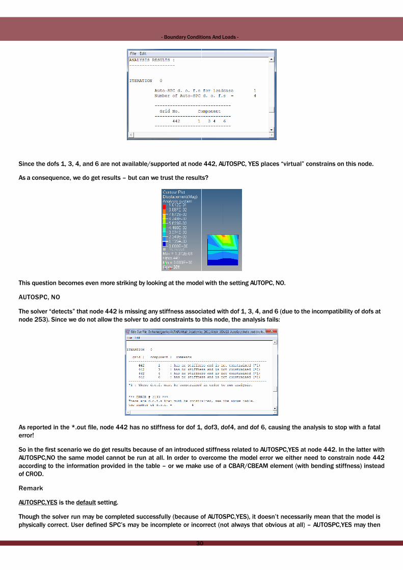
Since the dofs 1, 3, 4, and 6 are not available/supported at node 442,Since the dofs 1, 3, 4, and 6 are not available/supported at node 442,
As a consequence, we do get results – but can we trust the results?As a consequence, we do get results – but can we trust the results?
This question becomes even more striking by looking at the model This question becomes even more striking by looking at the model
AUTOSPC, NOAUTOSPC, NO
The solver “detects” that node 442 is missing any stiffness associaThe solver “detects” that node 442 is missing any stiffness associa
node 253). Since we do not allow the solver to add constraints to node 253). Since we do not allow the solver to add constraints to
As reported in the *.out file, node 442 has no stiffness for dof 1,As reported in the *.out file, node 442 has no stiffness for dof 1,
error!error!
So in the first scenario we do get results because of an introducedSo in the first scenario we do get results because of an introduced
AUTOSPC,NO the same model cannot be run at all. In order to oAUTOSPC,NO the same model cannot be run at all. In order to o
according to the information provided in the table – or we makeaccording to the information provided in the table – or we make
of CROD.of CROD.
RemarkRemark
AUTOSPC,YES is the default setting.AUTOSPC,YES is the default setting.
Though the solver run may be completed successfully (because ofThough the solver run may be completed successfully (because of
physically correct. User defined SPC’s may be incomplete or incorrectphysically correct. User defined SPC’s may be incomplete or incorrect
3030
Conditions And Loads -Conditions And Loads -
node 442, AUTOSPC, YES places “virtual” constrains on this node. node 442, AUTOSPC, YES places “virtual” constrains on this node.
results?results?
model with the setting AUTOPC, NO.model with the setting AUTOPC, NO.
associated with dof 1, 3, 4, and 6 (due to the incompatibility of dofs atassociated with dof 1, 3, 4, and 6 (due to the incompatibility of dofs at
o this node, the analysis fails:o this node, the analysis fails:
, dof3, dof4, and dof 6, causing the analysis to stop with a fatal, dof3, dof4, and dof 6, causing the analysis to stop with a fatal
oduced stiffness related to AUTOSPC,YES at node 442. In the latter withoduced stiffness related to AUTOSPC,YES at node 442. In the latter with
overcome the model error we either need to constrain node 442overcome the model error we either need to constrain node 442
use of a CBAR/CBEAM element (with bending stiffness) insteaduse of a CBAR/CBEAM element (with bending stiffness) instead
of AUTOSPC,YES), it doesn’t necessarily mean that the model isof AUTOSPC,YES), it doesn’t necessarily mean that the model is
incorrect (not always that obvious at all) – AUTOSPC,YES may thenincorrect (not always that obvious at all) – AUTOSPC,YES may then
3030

- Boundary Conditions - Boundary Conditions
automatically add further constraints which may lead to intriguingautomatically add further constraints which may lead to intriguing
Make sure and always check the *.out file for additional information.Make sure and always check the *.out file for additional information.
dofs (constraints) as listed in the *.out file and AUTOSPC,NO.dofs (constraints) as listed in the *.out file and AUTOSPC,NO.
6. Recommended Tutorials And Videos6. Recommended Tutorials And Videos6. Recommended Tutorials And Videos
Recommended Tutorials:Recommended Tutorials:
The following tutorials are included in your HyperWorks installation (see The following tutorials are included in your HyperWorks installation (see
• HM-4000: Setting up Loading Conditions• HM-4000: Setting up Loading Conditions
• HM-4040: Working with Loads on Geometry• HM-4040: Working with Loads on Geometry
Recommended VideosRecommended Videos
Creating boundary conditionsCreating boundary conditions
(http://altair-2.wistia.com/medias/3m5mzg42dn)(http://altair-2.wistia.com/medias/3m5mzg42dn)
Loads and constraintsLoads and constraints
(http://altair-2.wistia.com/medias/tq0gr7zafo)(http://altair-2.wistia.com/medias/tq0gr7zafo)
3131
Conditions And Loads -Conditions And Loads -
o intriguing results as depicted by the examples shown above.o intriguing results as depicted by the examples shown above.
ormation. Also, you may run the model again, this time applying theormation. Also, you may run the model again, this time applying the
orks installation (see HyperWorks help documentation).orks installation (see HyperWorks help documentation).
3131

- Boundary Conditions - Boundary Conditions
Loadstep definitionLoadstep definition
(http://altair-2.wistia.com/medias/52c93wwc5x)(http://altair-2.wistia.com/medias/52c93wwc5x)
Where Do You Get Your Loads To Assess ComponentWhere Do You Get Your Loads To Assess Component
Strength And DurabilityStrength And Durability
(http://altair-2.wistia.com/medias/91h98xs0h9)(http://altair-2.wistia.com/medias/91h98xs0h9)
More General (not HyperWorks related)More General (not HyperWorks related)
Distributed loads in finite elements, part Distributed loads in finite elements, part
1 (Prof. J. Chessa; University Texas; 1 (Prof. J. Chessa; University Texas;
http://youtu.be/8lwJQmDo7zQ)http://youtu.be/8lwJQmDo7zQ)
3232
Conditions And Loads -Conditions And Loads -
3232

- Boundary Conditions - Boundary Conditions
Distributed loads in finite elements, part 2
(Prof. J. Chessa; University Texas; http://youtu.be/gtBFrF7nt0s)(Prof. J. Chessa; University Texas; http://youtu.be/gtBFrF7nt0s)
Recommended Tips And Tricks (http://www.altairuniversity.com/Recommended Tips And Tricks (http://www.altairuniversity.com/
• Boundary Conditions – Loads Summary Tool• Boundary Conditions – Loads Summary Tool
• Beam - Pressure Loading• Beam - Pressure Loading
Presentation (PDF document)Presentation (PDF document)
Where are your loads coming from - Suspension and ChassisWhere are your loads coming from - Suspension and Chassis
(http://www.altairuniversity.com/wp-content/uploads/2013/07/Loads_Extraction_120309.pdf)(http://www.altairuniversity.com/wp-content/uploads/2013/07/Loads_Extraction_120309.pdf)
3333
Conditions And Loads -Conditions And Loads -
.com/hypermesh/).com/hypermesh/)
Chassis LoadsChassis Loads
7/Loads_Extraction_120309.pdf)7/Loads_Extraction_120309.pdf)
3333

- Boundary Conditions - Boundary Conditions
7. Student Racing Car Project - Bounda7. Student Racing Car Project - Bounda7. Student Racing Car Project - Bounda
BC’s & LoadsBC’s & Loads
Three different loadsteps are considered:Three different loadsteps are considered:
• Torsion• Torsion
• Bending• Bending
• Shear• Shear
In all three loadsteps the frame is constraint in the same way (seeIn all three loadsteps the frame is constraint in the same way (see
must be created.must be created.
ConstraintsConstraints
The corresponding nodes are fixed with respect to translational andThe corresponding nodes are fixed with respect to translational and
from the menu bar select BCs > Create > Constraints.from the menu bar select BCs > Create > Constraints.
300300
Conditions And Loads -Conditions And Loads -
Boundary ConditionsBoundary ConditionsBoundary Conditions
(see image below). Thus, 4 loadcollectors (no Card Images needed) (see image below). Thus, 4 loadcollectors (no Card Images needed)
and rotational displacements (dof 123456). To create constraints,and rotational displacements (dof 123456). To create constraints,
300300

- Boundary Conditions - Boundary Conditions
TorsionTorsion
Torsion is imposed through vertically applied forces. To create forces,Torsion is imposed through vertically applied forces. To create forces,
the referenced forces and magnitudes are just “dummy” assumptions. The the referenced forces and magnitudes are just “dummy” assumptions. The
The corresponding torsional loadstep is defined in the ”LoadStep” The corresponding torsional loadstep is defined in the ”LoadStep”
Bending &Bending &
ShearShear
The working steps related to the setup of the bending and shearThe working steps related to the setup of the bending and shear
bending and shear forces is shown in the images below. Care mustbending and shear forces is shown in the images below. Care must
collectors (no Card Image needed). The loadstep named “Bending”collectors (no Card Image needed). The loadstep named “Bending”
the loadstep “Shear” the loadcollectors “Shear” and “Constraint”.the loadstep “Shear” the loadcollectors “Shear” and “Constraint”.
Load case: Bending
3535
Conditions And Loads -Conditions And Loads -
ces, from the menu bar select BCs > Create > Forces. Of course ces, from the menu bar select BCs > Create > Forces. Of course
ptions. The frame is constrained as described before.ptions. The frame is constrained as described before.
ep” panel (Setup > Create > LoadSteps).ep” panel (Setup > Create > LoadSteps).
shear load cases are pretty much the same. The orientation of theshear load cases are pretty much the same. The orientation of the
must be taken, that these forces are stored in their respective loadmust be taken, that these forces are stored in their respective load
ing” then references the loadcollectors “Bending” and “Constraint”;ing” then references the loadcollectors “Bending” and “Constraint”;
..
Load case: Bending
3535

- Boundary Conditions - Boundary Conditions
Load case :ShearLoad case :Shear
This completes the model set-up. The model is saved as a binaryThis completes the model set-up. The model is saved as a binary
OptiStruct analysis deck (ASCII format).OptiStruct analysis deck (ASCII format).
3636
Conditions And Loads -Conditions And Loads -
case :Shearcase :Shear
y *.hm file (including CAD information) and then exported as any *.hm file (including CAD information) and then exported as an
3636


![TEXTILE MACHINE RY - · PDF filetextile machine ry. textile machine ry [1] [2] [3] textile machine ry. textile machinery. quattro . ran tee . vib0. system . created date: 8/30/2011](https://img.pdfslide.us/doc/110x75/5a6ffc397f8b9a98538b8d88/textile-machine-ry-biancalaniwwwbiancalanicomairoengpdfpdf.jpg)