Embed Size (px)
Citation preview

© 2021 Cisco Systems, Inc. All rights reserved.

Contents
Contents .................................................................................................................................................. 2
1 Solution Overview ............................................................................................................................. 1
Description ......................................................................................................................................... 1
Supported Use Cases .......................................................................................................................... 1
Solution Components and Integrated Architecture .................................................................................. 2
Supported Device Software ................................................................................................................. 7
Multi-Vendor Capabilities ..................................................................................................................... 7
Extensibility ......................................................................................................................................... 8
UI Overview ........................................................................................................................................ 8
2 Orchestrated Service Provisioning.................................................................................................. 12
Overview .......................................................................................................................................... 12
Scenario 1 - Implement and Maintain SLA for an L3VPN Service (using ODN)......................................... 13
Scenario 2 – Mandate a static path for an EVPN-VPWS service using an explicit SR-TE policy ................. 24
Scenario 3 – Provision an L2VPN service over an RSVP-TE tunnel with reserved bandwidth .................... 32
Scenario 4 – Provision a Soft Bandwidth Guarantee with Optimization Constraints................................... 39
3 Bandwidth and Network Optimization............................................................................................. 45
Overview .......................................................................................................................................... 45
Scenario 5 – Use Local Congestion Mitigation (LCM) to reroute traffic on an over-utilized link .................. 47
4 Network Maintenance Window ....................................................................................................... 55
Overview .......................................................................................................................................... 55
Scenario 6: Perform a software upgrade on a provider device during a scheduled maintenance window .. 56
5 Programmable Closed-Loop Auto-Remediation ............................................................................ 67
Overview .......................................................................................................................................... 67
Scenario 7 – Achieve Predictive Traffic Load Balancing Using Segment Routing Affinity .......................... 68
6 Automation of Onboarding and Provisioning of IOS-XR Devices Using ZTP.................................. 70
Overview .......................................................................................................................................... 70
Scenario 8 – Automatically onboard and provision new devices in the network ....................................... 71

1
1 Solution Overview
Description The exponential growth of network traffic and the pressures of efficiently running network operations pose huge challenges for network operators. Providing quick intent-based service delivery with optimal network utilization and ability to react to bandwidth and latency demand fluctuations in real time is vital to success. Migration to Software-Defined Networks (SDNs) and automation of daily operational tasks is the optimal way to become more efficient and competitive.
Cisco Crosswork Network Controller is a turnkey network automation solution for deploying and operating IP transport networks that delivers increased service agility, cost efficiency, and optimization for faster time-to-customer value and lower operating cost. The solution combines intent-based network automation to deliver critical capabilities for service orchestration and fulfilment, network optimization, service path computation, device deployment and management, and anomaly detection and automatic remediation. Using telemetry gathering and automated responses, Cisco Crosswork Network Controller delivers network optimization capabilities that would be nearly impossible to replicate even with a highly skilled and dedicated staff operating the network.
The fully integrated solution combines core capabilities from multiple innovative, industry-leading products including Cisco® Network Services Orchestrator (NSO), Cisco Segment Routing Path Computation Element (SR-PCE), and the Cisco Crosswork suite of applications. Its unified user interface allows real-time visualization of the network topology and services, as well as service and transport provisioning, via a single pane of glass.
Supported Use Cases ■ Orchestrated service provisioning: Provisioning of layer 2 (L2VPN) and layer 3 VPN (L3VPN) services
with underlay transport policies in order to define, meet, and maintain SLAs, using the UI or APIs. The ability to replace manual CLI-based configuration activities to API- or UI-guided activities saves time and improves the accuracy of configuration changes.
■ Real-time network and bandwidth optimization: Intent-based closed-loop automation, congestion mitigation and dynamic bandwidth management based on Segment Routing and RSVP-TE. Optimization of bandwidth resource utilization by setting utilization thresholds on links and calculating tactical alternate paths when thresholds are exceeded. Real-time telemetry is used to detect changes in network traffic and then changes in the network are automatically implemented to deliver on the operator's intent.
■ Local Congestion Management: Cisco Crosswork Network Controller 2.0 introduces support for Local Congestion Mitigation (LCM) which provides localized mitigation recommendations within surrounding interfaces, with the use of standard protocols. Data is gathered in real-time and when congestion is detected, solutions are suggested. LCM has a “human in the loop” aspect where the control of making changes in the network is in the hands of the operator.
■ Visualization of network and service topology and inventory: Visibility into device and service inventory and visualization of devices, links, and transport/VPN services and their health status on logical maps or within their geographical context.
■ Performance-based closed-loop automation: Automated discovery and remediation of problems in the network by allowing Key Performance Indicator (KPI) customization and monitoring and triggering of pre-

2
defined remediation tasks when a KPI threshold is breached. Cisco Crosswork Health Insights and Cisco Crosswork Change Automation must be installed for this use case.
■ Planning, scheduling, and automating network maintenance tasks: Scheduling an appropriate maintenance window for a maintenance task after evaluating the potential impact of the task (using WAE Design). Automating the execution of maintenance tasks (such as throughput checks, software upgrades, SMU installs) using playbooks. Cisco Crosswork Health Insights and Change Automation must be installed for this use case.
■ Secured zero-touch onboarding and provisioning of devices: Onboarding new IOS-XR devices and provisioning Day0 configuration automatically, resulting in faster deployment of new hardware at a lower operating cost. Cisco Crosswork Zero Touch Provisioning must be installed for this use case.
Solution Components and Integrated Architecture The following diagram provides a high-level illustration of how the solution’s components work together within a single pane of glass to execute the primary supported use cases.
Note: Crosswork Zero Touch Provisioning, Device Health Monitoring (Crosswork Health Insights), and Crosswork Network Change Automation are optional add-on components.
The following components make up the Cisco Crosswork Network Controller 2.0 solution:
■ Cisco Crosswork Active Topology

3
■ Cisco Crosswork Optimization Engine
■ Cisco Crosswork Data Gateway (CDG)
■ Crosswork Common UI and API
■ Crosswork Infrastructure and Shared Services
■ Cisco Crosswork Health Insights and Cisco Crosswork Change Automation
■ Cisco Crosswork Zero-Touch Provisioning (ZTP)
■ Cisco Network Services Orchestrator (NSO)
■ Cisco Segment Routing Path Computation Element (SR-PCE)
Cisco Crosswork Active Topology
Cisco Crosswork Active Topology’s logical and geographical maps provide real-time visibility into the physical and logical network topology, service inventory, and SR-TE policies and RSVP-TE tunnels, all within a single pane of glass. They enable operators to see, at-a-glance, the status and health of the devices, services, and policies. Services and transport policies can be visualized end-to-end as an overlay within the context of the topology map. Cisco Crosswork Active Topology provides device grouping functionality so that operators can set up their maps to monitor exactly the set of devices, services, and locations for which they are responsible. In addition, operators can save custom views for quick and easy access to the views and functionality they use on an ongoing basis.
Cisco Crosswork Optimization Engine
Cisco Crosswork Optimization Engine provides real-time network optimization allowing operators to effectively maximize network capacity utilization, as well as increase service velocity. Leveraging real-time protocols such as BGP-LS and Path Computation Element Communication Protocol (PCEP), SR-PCE and Crosswork Optimization Engine enable closed-loop tracking of the network state, reacting quickly to changes in network conditions to support a self-healing network.
Cisco Crosswork Data Gateway (CDG)
Cisco Crosswork Data Gateway is a secure, common collection platform for gathering network data from multi-vendor devices. It is an on-premise application deployed close to network devices that supports multiple data collection protocols including MDT, SNMP, CLI, standards-based gNMI (dial-in), and syslog. Any type of data can be collected by Crosswork Data Gateway as long as it can be delivered over one of the supported protocols. In this way, it can provide support for an undefined set of use cases and customizations.
To address scale challenges, Cisco Crosswork Data Gateway is implemented as a number of VMs and designed with a distributed architecture in mind. Each lightweight VM manages a subset of the overall network and as the network grows, additional VMs can be added horizontally to address the new demands on the compute resources. After initial setup, Cisco Crosswork Network Controller automatically orchestrates the collection across the multiple Cisco Crosswork Data Gateway VMs. APIs and configuration examples are available to illustrate how to add new collection jobs (outside of those built for you by Cisco Crosswork Network Controller) to gather additional information from your network. The collected data can be published to approved destinations. Supported destinations are Kafka and gRPC messaging bus.

4
Crosswork Common UI and API
All of Cisco Crosswork Network Controller’s functionality is provided within a single, common graphical user interface. This common UI brings together the features of all of Crosswork Network Controller’s components, including common inventory, network topology and service visualization, service and transport provisioning, and system administration and management functions. When optional add-on Crosswork components are installed, their functionality is also fully integrated into the common UI. Having all functionality within a common UI instead of having to navigate individual application UIs enhances the operational experience and increases productivity.
Common APIs enable Crosswork Network Controller’s programmability. The common API provides single access point for all APIs exposed by the various built-in components. The API provides a REST-based Northbound Interface to external systems (e.g., OSS systems) to integrate with Cisco Crosswork Network Controller. RESTCONF and YANG data models are made available for optimization use cases. For details about the APIs and examples of their usage, see the Cisco Crosswork Network Automation API Documentation on Cisco DevNet.
Crosswork Infrastructure and Shared Services
The Cisco Crosswork Infrastructure provides a resilient and scalable platform on which all of the Cisco Crosswork applications can be deployed. It is a microservices-based platform that brings together streaming telemetry and model-driven application programming interfaces (APIs) to redefine service provider network operations. It retrieves real-time information from the network, analyzes the data, and uses APIs to apply network changes. It employs a cluster architecture to be extensible, scalable, and highly available.
Cisco Crosswork Health Insights and Cisco Crosswork Change Automation
Cisco Crosswork Health Insights and Cisco Crosswork Change Automation are applications that can optionally be installed with Cisco Crosswork Network Controller.
Cisco Crosswork Health Insights is a network health application that performs real-time Key Performance Indicator (KPI) monitoring, alerting, and troubleshooting. Cisco Crosswork Health Insights enables programmable monitoring and analytics. It provides a platform for addressing changes to the network infrastructure dynamically. Cisco Crosswork Health Insights builds dynamic detection and analytics modules that allow operators to monitor and alert on network events based on user-defined logic.
The Cisco Crosswork Change Automation application automates the process of deploying changes to the network. Orchestration is defined via an embedded Ansible Playbook and then configuration changes are pushed to Cisco Network Services Orchestrator (NSO) to be deployed to the network.
These applications within Cisco Crosswork Network Controller enable closed-loop discovery and remediation of problems in the network. Operators can match alarms to pre-defined remediation tasks which are automatically performed when a defined Key Performance Indicator (KPI) threshold has been breached. This reduces the time it takes to discover and repair a problem while minimizing the risk of human error through manual network operator intervention.

5
Cisco Crosswork Zero-Touch Provisioning (ZTP)
Cisco Crosswork ZTP is an application that can optionally be installed with Cisco Crosswork Network Controller.
Cisco Crosswork ZTP is an integrated turnkey solution for onboarding and provisioning new IOS-XR devices automatically, resulting in faster deployment of new hardware at a lower operating cost. Operators can quickly and easily bring up devices using a Cisco-certified software image and a day-zero software configuration. Once provisioned in this way, the new device is onboarded to the Crosswork device inventory where it can be monitored and managed like other devices.
Cisco Crosswork ZTP now offers Secure ZTP functionality in addition to the Classic ZTP functionality. Secure ZTP is based on RFC 8572 standards and uses secure transport protocols and certificates to verify devices and perform downloads. Secure ZTP is useful when public Internet resources must be traversed to reach the remote network devices, or when the devices are from third-party manufacturers. With Secure ZTP, the device and the Cisco Crosswork ZTP bootstrap server authenticate each other using the device's Secure Unique Device Identifier (SUDI) and Crosswork server certificates over TLS/HTTPS. Once a secure HTTPS channel is established, the Crosswork bootstrap server allows the device to request to download and apply a set of signed image and configuration artifacts adhering to the RFC 8572 YANG schema. Once the image (if any) is downloaded and installed, and the device reloads with the new image, the device downloads configuration scripts and executes them.
Cisco Network Services Orchestrator (NSO)
Cisco Network Services Orchestrator (NSO) is an orchestration platform that makes use of pluggable function packs to translate network-wide service intent into device-specific configuration. Cisco NSO provides flexible service orchestration and lifecycle management across physical network elements and cloud-based virtual network functions (VNFs), fulfilling the role of the Network Orchestrator (NFVO) within the ETSI architecture. It provides complete support for physical and virtual network elements, with a consistent operational model across both. It can orchestrate across multi-vendor environments and support multiple technology stacks, enabling extension of end-to-end automation to virtually any use case or device.
Cisco NSO has a rich set of APIs designed to allow developers to implement service applications. It provides the infrastructure for defining and executing the YANG data models needed to realize customer services and is also responsible for providing the overall lifecycle management at the network service level.
Service and device models, written using YANG modelling language, enable Cisco NSO to efficiently ‘map’ service intent to device capabilities and automatically generate the minimum required configuration to be deployed in the network. This feature, facilitated by Cisco NSO’s FASTMAP algorithm, is capable of comparing current configuration states with a service’s intent and generating the minimum set of changes required to instantiate the service in the network.
All of the Crosswork applications that are included in Cisco Crosswork Network Controller or are optional add-ons require integration with Cisco NSO (with the exception of Cisco Crosswork ZTP).
Cisco Crosswork Network Controller is packaged with the following Cisco NSO function packs:
■ SR-TE core function pack (CFP) enables provisioning of explicit and dynamic segment routing policies, including on-demand SR-TE policy instantiation for prefixes with a specific color.
■ Sample function packs for IETF-compliant L2VPN and L3VPN provisioning. These function packs provide baseline L2VPN and L3VPN provisioning capabilities, based on IETF NM models. Prior to customization, these sample function packs enable provisioning of the following VPN services:
6
— L2VPN:
- Point-to-point VPWS using Targeted LDP
- Point-to-point VPWS using EVPN
— L3VPN
Note: By default, the IETF-compliant NM models are used. If your organization wishes to continue to use the Flat models that were provided with the previous version, a manual setup process is required. Consult your Cisco Customer Experience representative for more information.
■ Sample IETF-compliant RSVP-TE function pack intended as a reference implementation for RSVP-TE tunnel provisioning, to be customized as required.
Note: The Cisco NSO sample function packs are provided as a starting point for VPN service provisioning functionality in Cisco Crosswork Network Controller. While the samples can be used “as is” in some limited network configurations, they are intended to demonstrate the extensible design of Cisco Crosswork Network Controller. Answers to common questions can be found on Cisco Devnet and Cisco Customer Experience representatives can provide answers to general questions about the samples. Support for customization of the samples for your specific use cases can be arranged through your Cisco account team.
Cisco Segment Routing Path Computation Element (SR-PCE)
Cisco SR-PCE is an IOS-XR multi-domain stateful PCE supporting both segment routing (SR) and Resource Reservation Protocol (RSVP). Cisco SR-PCE builds on the native Path Computation Engine (PCE) abilities within IOS-XR devices, and provides the ability to collect topology and segment routing IDs through BGP-LS, calculate paths that adhere to service SLAs, and program them into the source router as an ordered list of segments. A Path Computation Client (PCC) reports and delegates control of head-end tunnels sourced from the PCC to a PCE peer. The PCC and PCE establish a Path Computation Element Communication Protocol (PCEP) connection that SR-PCE uses to push updates to the network and re-optimize paths where necessary.
Cisco SR-PCE can either reside on server resources using virtualized XRv9000 , or as a converged application running within IOS-XR Routers.

7
Supported Device Software
OS Version SR-PCE PCE-Init PCC-
Init
NSO+CFP Crosswork
Infrastructure
4.0
Optimization
Engine
ZTP
CLI NETCONF
IOS-
XR
6.5.3 yes yes yes
6.6.3 yes yes yes yes yes yes
7.0.2 yes yes yes yes yes
7.1.2 yes yes yes yes yes yes
7.2.1 yes yes yes yes yes
7.3.1 yes yes
(Cisco
ASR9000
Series
only)
yes yes yes yes yes yes
IOS-
XE
17.4.1 yes yes yes yes
Multi-Vendor Capabilities Today’s networks have typically been built up over time and incorporate multiple vendors and multiple generations of hardware and software. Furthermore, there is a lack of industry standardization, making support for these networks using a single tool challenging.
Service providers require an integrated solution to manage third-party devices that will reduce operational expenses and maintenance overhead, as well as eliminate the need to build custom operational applications to deploy and maintain different vendor products for a single network.
Because it uses standards-based protocols, Cisco Crosswork Network Controller is multi-vendor capable for:
■ Network service orchestration via Cisco NSO using CLI and Netconf/YANG. Cisco NSO is a YANG model-driven platform for automating provisioning, monitoring, and managing applications and services across multi-vendor networks.
■ Telemetry data collection using SNMP with standards-based MIBs, syslog, and gNMI with standard OpenConfig models. Cisco CDG also supports Native YANG data models for external destinations and proprietary SNMP MIBs with custom packages.
■ Topology and transport discovery via SR-PCE, using IGP and BGP-LS, with link utilization and throughput collected via SNMP using standard MIBs.
■ Transport path computation using PCEP.
Note: For third-party network device support, use cases must be validated by Cisco Customer Experience representatives in the customer’s multi-vendor environment, especially if legacy platforms and non-standard devices/services are involved.

8
Extensibility The Cisco Crosswork Network Controller provisioning functionality can be extended using the product application programming interfaces (APIs). For more information about the product APIs, see the Cisco Crosswork Network Automation API Documentation on Cisco DevNet.
The provisioning UI is extensible as it is rendered based on the Yang model, so when new services are introduced, they can be easily incorporated.
UI Overview
Log In
Log into the web UI by entering the following URL in the browser’s address bar:
https://<Crosswork Management Network Virtual IP (IPv4)>:30603/
or https://[<Crosswork Management Network Virtual IP (IPv6)>]:30603/
Note: The IPv6 address in the URL must be enclosed with brackets.
In the Log In window, enter the username and password configured during installation and click Log In.
Upon first-time access, some browsers display a warning that the site is untrusted. When this happens, follow the prompts to add a security exception and download the self-signed certificate from the server. After you do this, the browser accepts the server as a trusted site in all future login attempts.
Dashboard
After successful login, the Home page opens. The Home page displays the dashboard which provides an at-a-glance operational summary of the network being managed, including reachability and operational status of devices, as well as transport policies and VPN services. The dashboard is made up of a series of dashlets. The specific dashlets included in the dashboard depend on which Cisco Crosswork applications are installed. Links in each dashlet allow you to drill down for more details.

9
Navigation
The main menu along the left side of the window provides access to all features and functionality in Cisco Crosswork Network Controller, as well as to device management and administrative tasks. The Home, Topology, Services & Traffic Engineering, Device Management and Administration menu options are available when all native components of Cisco Crosswork Network Controller are installed. Additional menu options are available in the main menu depending on which Cisco Crosswork add-on applications are installed.
Home
The home page contains the dashboard, as described in Dashboard above.
Topology
The network topology can be displayed on a logical map or a geographical map (geo map), where the devices and links are shown in their geographic context. The logical map shows devices and their links, positioned according to an automatic layout algorithm, ignoring their geographical location. The geo map shows single devices, device groups, device clusters, links, and tunnels, superimposed on a map of the world. Each device location on the map reflects the device's GPS coordinates (longitude and latitude).
The Topology page consists of a map showing managed devices and the links between them along with a device table listing managed devices. In the map you can see the status and health of the devices at a glance. Clicking on a device in the table highlights the device on the map and shows details of the device and its associated links. Use the toggle buttons to switch between the logical map (shown below) and the geographical map.

10
Services & Traffic Engineering
The Services & Traffic Engineering menu provides access to VPN and transport provisioning and visualization functionality, as well as bandwidth management functionality.
Choose VPN services or Traffic Engineering to see managed VPN services or segment routing policies/RSVP-TE tunnels within the context of a logical or geographical map.
Choose Provisioning to access the provisioning UI rendered from the Cisco NSO models. Here you can create L2VPN and L3VPN services, SR-TE policies, SR ODN templates, and RSVP-TE tunnels. You can also create the resources required for these services and policies, such as resource pools, route policies for L2VPN and L3VPN services, and SID lists for SR-TE policies. SR-TE policies and RSVP-TE tunnels can be attached to VPN services to define and maintain SLAs by tracking network changes and automatically reacting to optimize the network.

11
Device Management
The Device Management menu provides access to device-related functionality, including adding, managing, and grouping devices, creating and managing credential profiles, and viewing a history of device-related jobs.
Administration
The Administration menu provides access to all system management functions, data gateway management, Crosswork cluster and application health, backup and restore, smart licensing and other setup and maintenance functions that would typically be performed by an administrator.
Refer to the Cisco Crosswork Infrastructure 4.0 and Applications Administration Guide for information about these functions.

12
2 Orchestrated Service Provisioning
Overview
Objective
Provision VPN services with underlay transport policies in order to meet and maintain service-level agreements (SLA).
Challenge
The network state changes continuously and so quickly that it is difficult to track and react to network problems fast enough to avoid congestion and maintain SLAs. In a typical lifecycle, there is a feedback loop that traditionally requires manual intervention which is time- and resource-intensive.
Solution
With network automation, the objective is to automate the feedback loop to enable quicker reaction to and remediation of network events. With Cisco Crosswork Network Controller, network operators can orchestrate L2VPN and L3VPN services across the transport network via a programmable interface in a very quick and efficient manner. Segment routing traffic engineering (SR-TE) polices can be configured to continuously track network changes and automatically react to optimize the network. These SR-TE polices can serve as the underlay configuration for the VPN services in order to automatically maintain the SLAs.
The services required for this solution can be created and managed using the Cisco Crosswork Network Controller UI. L2/L3 VPN Yang model-based service intents are implemented using the Cisco NSO sample function packs which provide sample service models that can be extended and fine-tuned to meet customer needs.
Note: The Cisco NSO sample function packs are provided as a starting point for VPN service provisioning functionality in Cisco Crosswork Network Controller. While the samples can be used “as is” in some limited network configurations, they are intended to demonstrate the extensible design of Cisco Crosswork Network Controller. Answers to common questions can be found on Cisco Devnet and Cisco Customer Experience can provide answers to general questions about the samples. Support for customization of the samples for your specific use cases can be arranged through your Cisco account team.
How Does it Work?
1. User creates an SR-TE policy/ODN template with intent (e.g., bandwidth, latency) using the Cisco Crosswork Network Controller UI or APIs.
2. User creates a VPN service using the UI or APIs and specifies the following:
— The endpoints participating in the VPN
— Other required VPN parameters
— The SR-TE policy/ODN template to be associated with the VPN service
3. During the provisioning process for the above steps, Cisco NSO configures the SR-TE policy and the VPN service on the specified endpoints.

13
4. When the service is active, the network interacts with the SR-PCE to dynamically program the path that meets the intent in the configured SR-TE policy/ODN template. The headend device requests a path from the SR-PCE via PCEP (for dynamic SR-TE policies). If the request involves bandwidth, the SR-PCE gets the path from Cisco Crosswork Optimization Engine.
5. The SR-PCE sends the path to the headend device via PCEP and updates the headend if path changes are required.
Usage Scenarios
We will walk you through the following usage scenarios that illustrate the execution of the orchestrated service provisioning use case using the Cisco Crosswork Network Controller UI:
■ Scenario 1 - Implement and Maintain SLA for an L3VPN Service (using ODN)
■ Scenario 2 – Mandate a static path for an EVPN-VPWS service using an explicit SR-TE policy
■ Scenario 3 – Provision an L2VPN service over an RSVP-TE tunnel with reserved bandwidth
■ Scenario 4 – Provision a Soft Bandwidth Guarantee with Optimization Constraints
Additional Resources
■ For information about segment routing and segment routing policies, refer to the Cisco Crosswork Optimization Engine User Guide
■ Cisco NSO documentation is available here:
https://software.cisco.com/download/home/286323467/type/286283941/release/5.4.2
Scenario 1 - Implement and Maintain SLA for an L3VPN
Service (using ODN)
Scenario Context
This scenario walks you through the procedure for provisioning an L3VPN service that requires a specific SLA objective. In this example, lowest latency path is the SLA objective. The customer requires a low latency path for high priority traffic. The customer also wants to use disjoint paths, i.e., two unique paths that steer traffic from the same source and destination avoiding common links so that there is no single point o f failure.
This is achieved using Segment Routing (SR) On-Demand Next Hop (ODN). ODN allows a service head-end router to automatically instantiate an SR-TE policy to a BGP next-hop when required (on-demand). The headend is configured with an ODN template with a specific color that defines the SLA upon which the traffic path will be optimized when a prefix with the specified color is received (prefixes are defined in a route policy that is associated with the L3VPN).
Cisco Crosswork Network Controller continues to monitor the network and will automatically optimize the network based on the defined SLA, in a closed loop.

14
The following topology provides the base for this scenario:
In this scenario, we will:
■ Create a segment routing ODN template with a specific color on the endpoints to ensure that traffic is transported within an LSP (underlay) and that a best-path tunnel is created dynamically when a prefix with the specified color is received. The ODN template defines the SLA upon which you want to optimize the path. In this case, we will optimize on latency.
■ Request that the computed paths be disjoint – they will not share the same link.
■ Create an L3VPN service with 3 endpoints – PE-A, PE-B, and PE-C (this is the overlay configuration).
■ Create a route policy on each endpoint to be used to bind the L3VPN to the ODN template. This route policy adds a color attribute to the customer prefixes and advertises via BGP to other endpoints. This color attribute is used to indicate the SLA required for these prefixes.
■ Visualize how this overlay/underlay configuration optimizes the traffic path and automatically maintains the SLA.
Assumptions and Prerequisites
■ To use ODN, BGP peering for the prefixes should be configured between the endpoints/PEs. Usually for L3VPN, this is the VPNv4 and VPNv6 address family peering.
Workflow
■ Step 1: Create an ODN template to map color to an SLA objective and constraints
■ Step 2: Create a Route Policy
■ Step 3: Create a VPN profile
■ Step 4: Create and provision the L3VPN service
■ Step 5: Visualize the New VPN Service on the Map to See the Traffic Path
■ Step 6: Observe automatic network optimization

15
Step 1: Create an ODN template to map color to an SLA objective and constraints
In this step, we will create an ODN template on each endpoint. The ODN template specifies the color and the intent, in this case, latency and disjointness. This ODN template will be used to create tunnels dynamically (on-demand) when prefixes with matching colors are received via BGP. Traffic to these prefixes will be automatically steered into the newly created tunnels, thereby meeting the SLA objective and constraints intended for these prefixes and signaled using colors in the BGP routes. Disjointness constraints work by associating a disjoint group ID with the ODN template and all tunnels with the same disjoint group ID will be disjoint, i.e., they will use different links, nodes and shared risk link groups depending on how the disjoint groups are configured.
We will create the following ODN templates:
■ Headend PE-A, color 72, latency, disjoint path (link), group ID 16 - L3VPN_NM-SRTE-ODN_72-a
■ Headend PE-A, color 71, latency, disjoint path (link), group ID 16 - L3VPN_NM-SRTE-ODN_71-a
■ Headend PE-B and PE-C, color 70, latency - L3VPN_NM-SRTE-ODN_70
■ Headend PE-B, color 72, latency - L3VPN_NM-SRTE-ODN_72-b
■ Headend PE-C, color 71, latency - L3VPN_NM-SRTE-ODN_71-c
For example purposes, we will show how to create the first ODN template - L3VPN_NM-SRTE-ODN_72-a. The other ODN templates can be created using the same procedure.
Procedure
1. Go to Services & Traffic Engineering > Provisioning > SR-TE > ODN Template.
2. Click + to create a new template and give it a unique name. In this case, the name is L3VPN_NM-SRTE-ODN_72-a.
3. Choose the headend device, PE-A, and specify the color 72.
4. Under dynamic, select “latency” as the metric type. This is the SLA objective on which we are optimizing.
5. Select the pce check box to specify that the path should be computed by the SR-PCE, not by the Path Computation Client (PCC).

16
6. Define the required constraints. In this case, we want the computed paths to be disjoint in that they must not share a link. Under disjoint-path, choose link as the type, and specify a numeric group ID, in this case, 16.
7. Commit your changes or click Dry Run to check what will be configured on the devices before you commit.

17
8. Check that the new ODN template appears in the table and its provisioning state is Success. Click … in the Actions column and choose Config View to see the Yang model-based service intent data that details the ODN template you created.
9. Create the other ODN templates listed above in the same manner.

18
Step 2: Create a Route Policy
In this step, we will create a route policy for each endpoint and we will specify the same color as defined in the ODN template for that endpoint. The route policy defines the prefixes to which the SLA applies. When traffic from the specified network with a matching color is received, paths are computed based on the SLA defined in the ODN template.
We will create the following route policies:
■ Color 70, IPv4 prefix 70.70.70.0/30 - L3VPN_NM-SRTE-RP-PE-A-7
■ Color 71, IPv4 prefix 70.70.71.0/30 - L3VPN_NM-SRTE-RP-PE-B-7
■ Color 72, IPv4 prefix 70.70.72.0/30 - L3VPN_NM-SRTE-RP-PE-C-7
For example purposes, we will create the first route policy - L3VPN_NM-SRTE-RP-PE-A-7. The other route policies can be created using the same procedure.
Procedure
1. Go to Services & Traffic Engineering > Provisioning > L3vpn > L3vpn Route Policy.
2. Click + to create a new route policy and give it a unique name.
3. Under Color, click +. Specify the same color that is specified in the ODN template for PE-A, 70, and click Continue.
4. Enter the required IPv4 or IPv6 prefixes to identify the network traffic. In this case, IPv4 prefix 70.70.70.0/30.
5. Click X in the top right corner to close the Color pane.
6. Commit your changes.
7. Check that the new route policy appears in the table.

19
8. Create the other route policies listed above in the same manner.
Step 3: Create a VPN profile
In this step, we will create a VPN profile for each route policy. The VPN profile will be referenced from the L3VPN service. This will bind the route policy to the L3VPN service.
We will create the following VPN profiles for each of the route policies we created in the previous step:
■ L3VPN_NM-SRTE-RP-PE-A-7
■ L3VPN_NM-SRTE-RP-PE-B-7
■ L3VPN_NM-SRTE-RP-PE-C-7
Procedure
1. Go to Services & Traffic Engineering > Provisioning > L3vpn > VPN Profiles
2. Click + to create a new VPN profile.
3. From the dropdown list, choose the required route policy.
4. Commit your changes.
5. Check that the new VPN profile appears in the table.
6. Create the other VPN profiles listed above in the same manner.
Step 4: Create and provision the L3VPN service
In this step, we will create the L3VPN service with three endpoints: PE-A, PE-B, and PE-C. Each endpoint will be associated with an ie-profile which in turn points to a VPN profile which contains the route policy with the same color as specified in the ODN template. In this way, traffic that matches the specified prefixes and color will be treated according to the SLA specifications.
1. Go to Services & Traffic Engineering > Provisioning > L3vpn > L3vpn Service.
2. Click + to create a new service and give it a unique name. Click Continue.
3. Create an ie-profile which is a container that defines the route distinguisher (RD), route targets, and the export/import route policy. We will create an ie-profile for each endpoint, as follows:
— L3VPN_NM_SR_ODN-IE-PE-A-7 with route distinguisher 0:70:70
— L3VPN_NM_SR_ODN-IE-PE-B-7 with route distinguisher 0:70:71
— L3VPN_NM_SR_ODN-IE-PE-C-7 with route distinguisher 0:70:72
a. Under ie-profile, click + to create a new ie-profile and give it a unique name.
b. Enter the route distinguisher that will differentiate the IP prefixes and make them unique.
c. Define the required VPN targets, including route targets and route target types (import/export/both).

20
d. Under vpn-policies, in the export policy dropdown list, choose the relevant VPN profile (which contains the route policy). This forms the association between the VPN and the ODN template that defines the SLA.
e. Click X in the top right corner when you are done.
f. Similarly, create the other IE profiles.
4. Define each VPN endpoint individually – PE-A, PE-B, and PE-C.
a. Under vpn-nodes, click +, select the relevant device from the dropdown list and click Continue.
b. Enter the local autonomous system number for network identification.
c. Select the ie-profile you created in the previous step.
d. Define the network access parameters for communication from the PE towards the CE:
- Under vpn-network-accesses, click + to create a new set of VPN access parameters and provide a unique ID. Click Continue.
- In the port-id field, provide the name of a loopback interface that will be dedicated for this VRF.
- Under ip-connection > IPv4 > address-allocation-type, choose static-address.
- Under static-addresses, there is a table where you can create a list of IP addresses for network access for this endpoint. After creating at least one address, you can select a primary address. In the address table, click + to create a new address and provide a unique ID. Click Continue. Specify the IP address and prefix length of the loopback interface.
- Click X in the top right corner to return to the VPN network access parameters.
- Select the address you just created from the dropdown list in the primary-address field.

21
- Define BGP routing protocol parameters, including the peer AS number and local AS number, IP address type (IPv4), the IP address of the BGP neighbor, and the number of hops allowed between the BGP neighbor and the PE device.
e. Click X in the top right corner when you are done.
f. Repeat these steps for each endpoint.
5. Commit your changes or click Dry Run to check what will be configured on the devices before you commit.
6. Check that the new L3VPN service appears in the table and its provisioning state is Success.
Step 5: Visualize the New VPN Service on the Map to See the Traffic Path
1. In the L3VPN Service table, click on the service name or click … in the Actions column and choose View from the menu. The map opens and the service details are shown to the right of the map.
or
Go to Services & Traffic Engineering > VPN Services. The map opens and a table of VPN services is displayed to the right of the map.
Click on the VPN in the Services table. If there are many services in the table, you can filter by name, type, or provisioning state to help locate the VPN.
In the map, you will see the VPN as an overlay on the topology. It shows a representation of the three endpoints and a dashed line that indicates that it is a virtual path.
Note: The image below shows the VPN overlay in the logical map. Use the buttons at the top right of the
map to toggle between the logical and geographical maps.
Select the Show Participating Only check box if you do not want to see the devices that are not involved in the selected VPN.

22
2. In the Actions column, click … to drill down to a detailed view of the VPN service, including the device configurations and the computed transport paths.
3. To see the computed paths for this VPN, click on the Transport tab in the Service Details pane. All the dynamically created SR-TE policies are listed in the Transport tab. Select one or more SR-TE policies to see the path from endpoint to endpoint on the map.
In this example, we are looking at the disjoint paths computed from PE-A to PE-B and from PE-A to PE-C.

23
4. To see the physical path between the endpoints, select the Show IGP Path check box in the top left corner of the map. Hover with your mouse over a selected policy in the table to highlight the path in the map and show prefix SID and routing information.
Step 6: Observe automatic network optimization
The SR-PCE constantly monitors the network and automatically optimizes the traffic path based on the defined SLA. For illustration purposes, let’s take a look at what happens when one of the links goes down, in this case, the link between P-BOTTOMLEFT and P-BOTTOMRIGHT. This means that the previous path from PE-A to PE-C is no longer viable. Therefore, the SR-PCE computes an alternative path, both from PE-A to PE-C and from PE-A to PE-B, in order to compensate for the link that is down and to maintain the disjoint paths.
Recomputed paths:
Source and Destination Old path New path
PE-A > PE-C PE-A > P-BOTTOMLEFT >
P-BOTTOMRIGHT > PE-C
PE-A > P-TOPLEFT >
P-BOTTOMRIGHT > PE-C
PE-A > PE-B PE-A > P-TOPLEFT > P-TOPRIGHT >
PE-B
PE-A > P-BOTTOMLEFT >
P-TOPRIGHT > PE-C

24
Summary and Conclusion
As we observed in this example, operators can use Cisco Crosswork Network Controller to orchestrate L3VPNs with SLAs and to maintain these SLAs using SR-TE policies that continuously track network conditions and automatically react to optimize the network. This automation increases efficiency and reduces human error that is generally unavoidable with manual tasks.
Scenario 2 – Mandate a static path for an EVPN-VPWS service
using an explicit SR-TE policy
Scenario Context
To ensure that mission-critical traffic within a VPN traverses the higher capacity interfaces rather than the lower capacity interfaces, we will create a point-to-point EVPN-VPWS service and associate a preferred path (explicit) SR-TE policy on both endpoints for service instantiation. In this way, we will mandate a static path for the mission-critical traffic.
In this scenario, we will see how quick and easy it is to create SR-TE policies and VPN services by uploading a file containing all the required configurations. We will download sample files (templates) from the provisioning UI, fill in the required data, and then import the file via the UI.
In this scenario, we will:
■ Create a SID list - a list of prefix or adjacency Segment IDs, each representing a device or link along the path.
■ Provision an explicit SR-TE policy which will reference the SID list, thus creating a predefined path into which the EVPN prefix will be routed.
■ Provision a point-to-point EVPN-VPWS service from PE-A to PE-C and attach the explicit SR-TE policy.
■ Visualize the path of the service.
Assumptions and Prerequisites
For transport mapping to L2VPN service, devices must be configured with the “l2vpn all” command.

25
Workflow
■ Step 1: Prepare for Creating a SID List
■ Step 2: Create the SID List in the Provisioning UI
■ Step 3: Create an explicit SR-TE policy for each VPN endpoint by importing a file
■ Step 4: Create and provision the L2VPN
■ Step 5: Attach the SR-TE policies to the L2VPN Service
■ Step 6: Visualize the L2VPN on the Map
Step 1: Prepare for Creating a SID List
The SID list consists of a series of prefix or adjacency SIDs, each representing a node or link along on the path. Each segment is an end-to-end path from the source to the destination, and it instructs the routers in the network to follow the specified path instead of the shortest path calculated by the IGP.
To build the SID list, you will need the MPLS labels of the desired traversing path. You can get these labels from the devices themselves or you can invoke the northbound Cisco Crosswork Optimization Engine API to retrieve this information.
Refer to Cisco Crosswork Network Automation API Documentation on Cisco Devnet for more information about the API.
Procedure
1. Prepare the input required to produce the SID list for the path from endpoint to endpoint. You will need the router ID of each endpoint, as follows:
'{ "input": { "head-end": "100.100.100.7", "end-point": "100.100.100.5", "sr-policy-path": { "path-optimization-objective": "igp-metric" } } }'
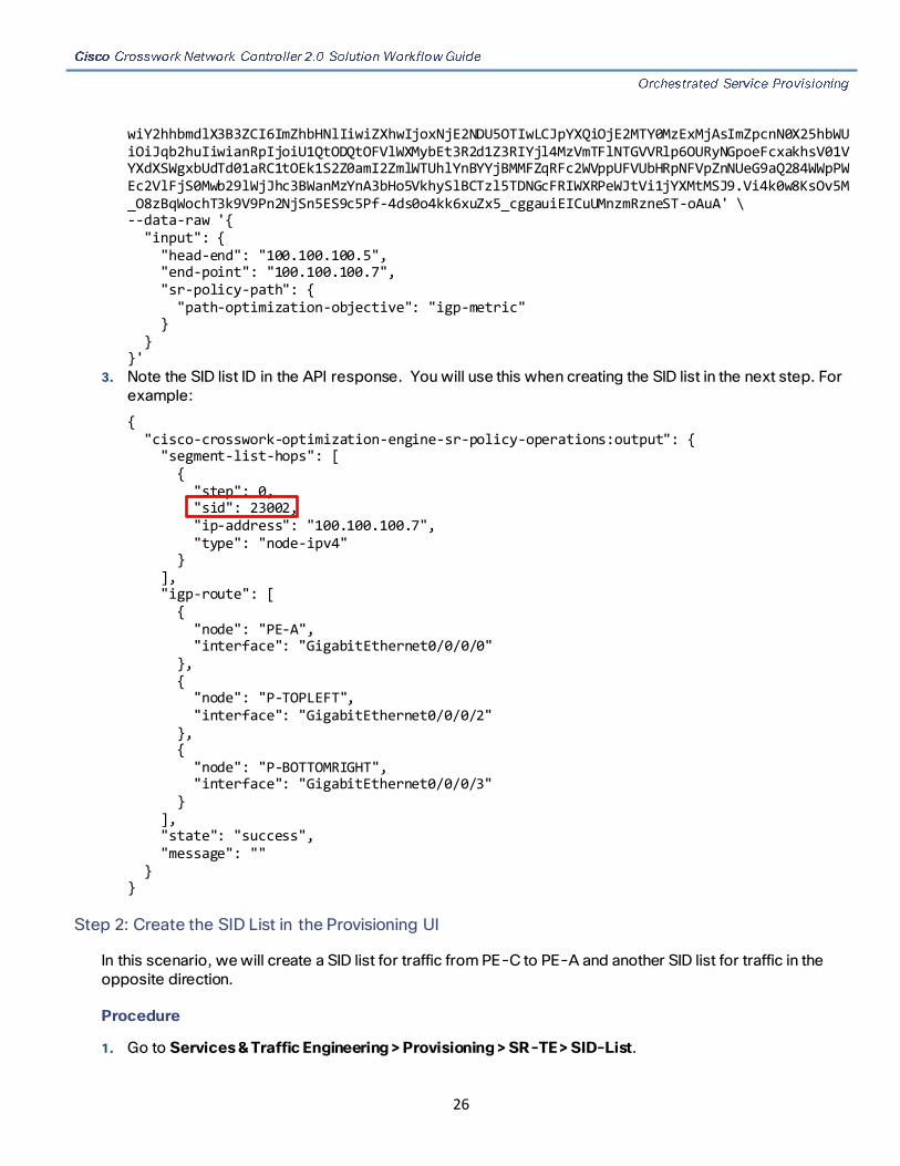
2. Invoke the API on the Cisco Crosswork Network Controller server using the input prepared in the previous step. For example:
curl --location --request POST 'https://10.194.63.198:30603/crosswork/nbi/optima/v1/restconf/operations/cisco-crosswork-optimization-engine-sr-policy-operations:sr-policy-dryrun' \ --header 'Content-Type: application/yang-data+json' \ --header 'Accept: application/yang-data+json' \ --header 'Authorization: Bearer eyJhbGciOiJIUzUxMiJ9.eyJzdWIiOiJhZG1pbiIsImlzRnJvbU5ld0xvZ2luIjoidHJ1ZSIsInBvbGljeV9pZCI6ImFkbWluIiwiYXV0aGVudGljYXRpb25EYXRlIjoiMjAyMS0wMy0yMlQxNjozODozNy43NDY2MTZaW0dNVF0iLCJzdWNjZXNzZnVsQXV0aGVudGljYXRpb25IYW5kbGVycyI6IlF1ZXJ5RGF0YWJhc2VBdXRoZW50aWNhdGlvbkhhbmRsZXIiLCJpc3MiOiJodHRwOlwvXC9sb2NhbGhvc3Q6NTQ4OVwvU1NPIiwibGFzdF9uYW1lIjoic21pdGgiLCJjcmVkZW50aWFsVHlwZSI6IlVzZXJuYW1lUGFzc3dvcmRDcmVkZW50aWFsIiwiYXVkIjoiaHR0cHM6XC9cLzEwLjE5NC42My4xOTg6MzA2MDNcL2FwcC1kYXNoYm9hcmQiLCJhdXRoZW50aWNhdGlvbk1ldGhvZCI6IlF1ZXJ5RGF0YWJhc2VBdXRoZW50aWNhdGlvbkhhbmRsZXIiLCJsb25nVGVybUF1dGhlbnRpY2F0aW9uUmVxdWVzdFRva2VuVXNlZCI6ImZhbHNlIi
26
wiY2hhbmdlX3B3ZCI6ImZhbHNlIiwiZXhwIjoxNjE2NDU5OTIwLCJpYXQiOjE2MTY0MzExMjAsImZpcnN0X25hbWUiOiJqb2huIiwianRpIjoiU1QtODQtOFVlWXMybEt3R2d1Z3RIYjl4MzVmTFlNTGVVRlp6OURyNGpoeFcxakhsV01VYXdXSWgxbUdTd01aRC1tOEk1S2Z0amI2ZmlWTUhlYnBYYjBMMFZqRFc2WVppUFVUbHRpNFVpZnNUeG9aQ284WWpPWEc2VlFjS0Mwb29lWjJhc3BWanMzYnA3bHo5VkhySlBCTzl5TDNGcFRIWXRPeWJtVi1jYXMtMSJ9.Vi4k0w8KsOv5M_O8zBqWochT3k9V9Pn2NjSn5ES9c5Pf-4ds0o4kk6xuZx5_cggauiEICuUMnzmRzneST-oAuA' \ --data-raw '{ "input": { "head-end": "100.100.100.5", "end-point": "100.100.100.7", "sr-policy-path": { "path-optimization-objective": "igp-metric" } } }'
3. Note the SID list ID in the API response. You will use this when creating the SID list in the next step. For example:
{ "cisco-crosswork-optimization-engine-sr-policy-operations:output": { "segment-list-hops": [ { "step": 0, "sid": 23002, "ip-address": "100.100.100.7", "type": "node-ipv4" } ], "igp-route": [ { "node": "PE-A", "interface": "GigabitEthernet0/0/0/0" }, { "node": "P-TOPLEFT", "interface": "GigabitEthernet0/0/0/2" }, { "node": "P-BOTTOMRIGHT", "interface": "GigabitEthernet0/0/0/3" } ], "state": "success", "message": "" } }
Step 2: Create the SID List in the Provisioning UI
In this scenario, we will create a SID list for traffic from PE-C to PE-A and another SID list for traffic in the opposite direction.
Procedure
1. Go to Services & Traffic Engineering > Provisioning > SR-TE > SID-List.

27
2. Click + to create a new SID list and give it a unique name. For this example, the SID list name is L2VPN_NM-P2P-SRTE-PE-C-240. Click Continue.
3. Under sid, click + to create a new SID index and give it a numeric value. Click Continue.
4. Under mpls, enter the SID ID that was received in the API response in Step 1: Prepare for Creating a SID List.
5. Click X in the top right corner to return to the SID list. Your new SID appears in the index table.
6. Repeat these steps to create additional SID indexes, as required.
7. Commit your changes.
8. Check that the new SID list appears in the table.
9. Create another SID list for the traffic from PE-A to PE-C. For this example, the SID list name is L2VPN_NM-P2P-SRTE-PE-A-240.
Step 3: Create an explicit SR-TE policy for each VPN endpoint by importing a file
In this step, we will provision two explicit SR-TE policies which will reference the SID lists created in Step 1.
The first SR-TE policy specifies PE-C as the headend and provides the IP address of PE-A as the tail end. The second SR-TE policy specifies PE-A as the headend and provides the IP address of PE-C as the tail end.
Instead of manually filling in each field in the provisioning UI, we will import an xml file containing all the configurations required to create the SR-TE policy.
Procedure
1. Go to Services & Traffic Engineering > Provisioning > SR-TE > Policy.

28
2. Click Import above the table.
3. Download the sample .json or .xml file which will serve as a template for the required configuration. In the Import Service dialog, click the Download sample .json and .xml files (.zip) link.
4. Unzip the downloaded file and open sr-Policy.xml in an XML editor.
5. Edit the xml file as required. Provide a name for the SR-TE policy and specify the SID list to be associated with this policy. Save the xml file.
6. In the Import Service dialog, select Policy as the type of file to import, browse to the edited xml file, and click Import. If there are any errors in the file, you will be notified. If there are no errors, the file will be imported. The policy will be created and the devices will be configured accordingly.
7. Check that the new SR-TE policy appears in the Policy table and its Provisioning State is Success.
8. Click … in the Actions column and choose Config View to see to see the Yang model-based service intent data that details the SR-TE policy you created. You can also check the devices themselves to make sure that they were provisioned correctly.
29
Step 4: Create and provision the L2VPN service
In this step, we will create and provision a P2P VPN service with PE-A and PE-C as the endpoints. The VPN service will reference the SR-TE policies we created in the previous step to ensure that the traffic traversing the VPN will follow the path defined in the SID lists.
As we did with the SR-TE policy, we will create the VPN service by importing an xml file containing all the required configurations. Once we have provisioned the VPN service, we will edit it in the provisioning UI in order to associate the SR-TE policies.
Procedure
1. Go to Services & Traffic Engineering > Provisioning > L2vpn > L2vpn Service.
2. Click Import above the table.
3. If you did not download the sample .json or .xml files in Step 3: Create an explicit SR-TE policy for each VPN endpoint by importing a file, do so now.
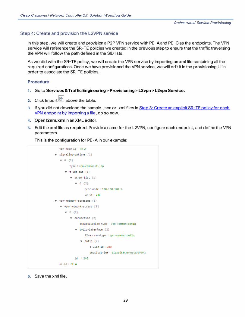
4. Open l2nm.xml in an XML editor.
5. Edit the xml file as required. Provide a name for the L2VPN, configure each endpoint, and define the VPN parameters.
This is the configuration for PE-A in our example:
6. Save the xml file.

30
7. In the Import Service dialog, select l2vpn service as the type of file to import, browse to the edited xml file, and click Import. If there are any errors in the file, you will be notified. If there are no errors, the file will be imported. The policy will be created and the devices will be configured accordingly.
8. Check that the new L2VPN service appears in the L2VPN Service table and its Provisioning State is Success.
9. Click … in the Actions column and choose Config View to see the Yang model-based service intent data that details the VPN service you created. You can also check the devices themselves to make sure that they were provisioned correctly.
Step 5: Attach the SR-TE policies to the L2VPN Service
At this stage, the provisioned L2VPN service you created does not have associated SR-TE policies that define the transport path. In this step, we will edit the L2VPN service in the provisioning GUI, attach the relevant SR-TE policies to each endpoint, and re-provision it.
Procedure
1. Locate the L2VPN in the VPN Service table.
2. Click … in the Actions column and choose Edit.
3. Under vpn-nodes, select PE-A and click the Edit button above the table.
4. In the pane that opens on the right, open the te-service-mapping > te-mapping section.
5. In the sr-policy tab, in the policy field, enter the name of the SR-TE policy created for PE-A: L2VPN_NM-P2P-SRTE-PE-A-240
6. Click X in the top right corner to close the PE-A pane.
7. Repeat the above steps for PE-C and attach the SR-TE policy: L2VPN_NM-P2P-SRTE-PE-C-240.
8. Click Commit Changes.
Step 6: Visualize the L2VPN on the Map
In this step we’ll take a look at the representation of the L2VPN on the map and we’ll see the paths the traffic will take from PE-A to PE-C and vice versa, based on the explicit SR-TE policies we created.
Procedure
1. In the L2VPN Service table, in the Actions column for the new VPN, click … and choose View from the menu. The map opens and the service details are shown to the right of the map.
or
Go to Services & Traffic Engineering > VPN Services. The map opens and a table of VPN services is displayed to the right of the map.
Click on the VPN in the Services table. If there are many services in the table, you can filter by name, type, or provisioning state to help locate the VPN.
In the map, you will see the VPN as an overlay on the topology. It shows a representation of the endpoints and a dashed line that indicates that it is a virtual path.

31
Note: The image below shows the VPN overlay in the geographical map. Use the buttons at the top right
of the map to toggle between the logical and geographical maps.
Select the Show Participating Only check box if you do not want to see the devices that are not involved in the selected VPN.
2. Under the Actions column, click … and choose View Details to drill down to a detailed view of the VPN service, including the device configurations and the computed transport paths.
3. In the Transport tab, select one or more SR-TE policies to see the path from endpoint to endpoint on the map. The image below shows the path for PE-C to PE-A. The Show IGP Path check box in the top left corner of the map is selected so the physical path is shown. The dashed line indicates that this link is being used to transport multiple services.

32
Summary and Conclusion
In this scenario, we observed how simple it is to create explicit SR-TE policies and attach them to a L2VPN service in order mandate a static path for the mission-critical traffic. We saw how editing a pre-defined template and then importing it into the system enables quick and easy provisioning of services and SR-TE policies. We were then able to visualize the actual traffic paths on the map.
Scenario 3 – Provision an L2VPN service over an RSVP-TE
tunnel with reserved bandwidth
Scenario Context
For the continuous stream transmission required for rich data media types such as video and audio, bandwidth reservation is often required to provide higher quality of service. Cisco Crosswork Network Controller supports the creation and management of RSVP-TE tunnels to reserve guaranteed bandwidth for an individual flow. RSVP is a per-flow protocol that requests a bandwidth reservation from every node in the path of the flow. The endpoints, or other network devices on behalf of the endpoints, send unicast signaling messages to establish the reservation before the flow is allowed. If the total bandwidth reservation exceeds the available bandwidth for a particular LSP segment, the LSP is rerouted through another LSR. If no segments can support the bandwidth reservation, LSP setup fails and the RSVP session is not established.

33
In this scenario we will:
■ Create RSVP-TE tunnels with reserved bandwidth.
■ Enable Bandwidth on Demand functionality.
■ Provision a VPN service from PE-A to PE-B and attach the RSVP-TE tunnels as underlay configuration.
■ Visualize the path of the traffic when link utilization is below the bandwidth threshold. This path would change if the bandwidth utilization on the link crossed the specified threshold.
Assumptions and Prerequisites
For transport mapping to L2VPN service, devices must be configured with the “l2vpn all” command.
Workflow
■ Step 1: Create an RSVP-TE tunnel for both directions of the L2VPN
■ Step 2: Create the L2VPN service and attach the RSVP tunnel to the service
■ Step 3: Visualize the L2VPN service on the map
Step 1: Create an RSVP-TE tunnel for both directions of the L2VPN
In this step, we will create an RSVP-TE tunnel from PE-A to PE-B and from PE-B to PE-A, and we’ll reserve bandwidth of 1200 on the link.
1. Go to Services & Traffic Engineering > Provisioning > RSVP-TE > Tunnel.
2. Click + to create a new RSVP-TE tunnel and give it a unique name. Click Continue.
3. In the Identifier field, enter a numeric identifier for the tunnel. You will use this identifier later when you associate this RSVP-TE tunnel with the L2VPN service. For this example, the identifier is 2220.

34
4. In the source and destination fields, enter the loopback0 IP address of the source (PE-A) and the destination (PE-B) devices. This is the TE router ID. To find the TE router ID, go to Topology and click on a device in the map or in the list of devices. The Device Details pane opens and the TE router ID is shown under the Routing section.
5. Define the endpoints:
a. Under head-end, select the headend device from the dropdown list.
b. Under tail-end, select the tailend device from the dropdown list.
6. Reserve bandwidth on the link. Under te-bandwidth > generic, enter the bandwidth threshold for the link.
7. Define the path of the RSVP-TE tunnel. You have the option to define an explicit path or to have the path locally computed by the participating devices. Alternatively, you can have the SR-PCE compute a path dynamically. For this scenario we will have the path locally computed.
a. Under p2p-primary-paths, click + to create a new path.
b. In the pane that opens on the right, give the path a name.
c. Select the path computation method – path-locally-computed.
d. Specify a numeric preference for the path. The lower the number, the higher the preference.

35
e. Define the optimization metric, in this case, igp.
8. Click Commit Changes.
9. Verify that the RSVP-TE tunnel appears in the list of tunnels and its Provisioning State is Success.

36
10. Click on the tunnel name to visualize the tunnel on the map and to see the tunnel details.
Step 2: Create the L2VPN service and attach the RSVP tunnel to the service
In this step, we will create a P2P L2VPN service using the provisioning GUI. If you want to create the service by importing a template, refer to Scenario 2 – Mandate a static path for an EVPN-VPWS service using an explicit SR-TE policy
1. Go to Services & Traffic Engineering > Provisioning > L2VPN > L2vpn Service.
2. Click + to create a new service and give it a unique name. Click Continue.
3. Choose vpn-common:t-ldp in the vpn-svc-type field.
4. Define each VPN endpoint individually – PE-A and PE-B.
a. Under vpn-nodes, click +.
b. Select the relevant device from the vpn-node-id and ned-id dropdown lists and click Continue.
c. Enter the local autonomous system number for network identification.
5. Define the LDP signaling options by creating one or more pseudowires. In this case, specify the TE router ID of the peer device (PE-B) and provide a unique numeric label to identify the pseudowire.
6. Attach the RSVP tunnel to the service:
a. Under te-service-mapping > te-mapping, click the te-tunnel-list tab.
b. Click the ietf-te-service tab.

37
c. Enter the name of the RSVP-TE tunnel you want to attach to this L2VPN service. The tunnel ID will be extracted from the tunnel configuration.
Note: If you have an RSVP-TE tunnel on the device that was configured externally to Cisco Crosswork Network Controller, you can simply provide the tunnel ID under the te-tunnel-id tab.
7. Define the VPN network access. In this case, we are using dot1q encapsulation and we have specified the physical interface (GigabitEthernet0/0/0/2) and the VLAN ID (2220).
8. Follow the above steps for PE-B as well.
9. Click Commit Changes. Verify that the L2VPN appears in the list of VPN services and that its Provisioning state is Success.

38
Step 3: Visualize the L2VPN service on the map
In this step we’ll take a look at the representation of the L2VPN on the map and we’ll see the paths the traffic will take from PE-A to PE-B and vice versa, based on the RSVP-TE tunnels we created.
Procedure
1. In the L2VPN Service table, click on the service name. The map opens and the service details are shown to the right of the map.
or
Go to Services & Traffic Engineering > VPN Services. The map opens and a table of VPN services is displayed to the right of the map.
Click on the VPN in the Services table. If there are many services in the table, you can filter by name, type, or provisioning state to help locate the VPN.
In the map, you will see the VPN as an overlay on the topology. It shows a representation of the three endpoints and a dashed line that indicates that it is a virtual path.
Note: The image below shows the VPN overlay in the geographical map. Use the buttons at the top right
of the map to toggle between the logical and geographical maps.
2. To see the hops in the route between PE-A and PE-B, click the Transport tab and select one or more of the underlying TE tunnels to see the path from endpoint to endpoint on the map. The image below shows

39
both RSVP-TE tunnels selected in the Transport tab and the route from PE-A to PE-B and from PE-B to PE-A is shown on the logical map.
3. As the RSVP-TE tunnels are configured with a reserved bandwidth, if the bandwidth utilization across the link exceeds the specified bandwidth, the path would be rerouted.
Summary and Conclusion
This scenario illustrated how to create RSVP-TE tunnels with reserved bandwidth and attach them to an L2VPN service to meet the high quality of service requirements for continuous streaming of rich data media. We observed the path on the map. This path would be recomputed if the bandwidth utilization on the link crossed the bandwidth reservation threshold.
Scenario 4 – Provision a Soft Bandwidth Guarantee with
Optimization Constraints
Scenario Context
Service providers must be able to provide fast connections with the lowest latency possible to meet the needs of customers’ peak traffic utilization times and to dynamically optimize services based on the customers’ changing priorities throughout the day. For this purpose, the operator might need to reserve bandwidth on specific links to ensure a dedicated path that can handle a set amount of traffic with a specific

40
optimization intent. The Bandwidth on Demand (BWoD) feature within Cisco Crosswork Network Controller enables this functionality. Paths with the requested bandwidth are computed when available. If a path that guarantees the requested bandwidth cannot be found, an attempt will be made to find a best effort path.
In this scenario, we will use BWoD to calculate the lowest TE metric path with a specified amount of available bandwidth between two endpoints.
This scenario uses the following topology as a base:
The goal is to create a path from F2.cisco.com to F7.cisco.com that can accommodate 250 Mbps of traffic while keeping the utilization at 80%. BWoD will initially try to find a single path to accommodate the requested bandwidth without exceeding the utilization threshold. If a single path cannot be found, BWoD may recommend splitting the path.
In this scenario we will:
■ Orchestrate a new SR-TE policy with bandwidth and TE constraints.
■ Configure and enable BWoD.
■ Verify the state of the SR-TE policy and view the path on the map
Workflow
■ Step 1: Create a BWoD SR-TE Policy with the Requested Bandwidth and Optimization Intent.
■ Step 2: Enable and Configure BWoD
■ Step 3: Verify that the policy’s operational state is now Up and view the path on the map
Step 1: Create a BWoD SR-TE Policy with the Requested Bandwidth and Optimization Intent.
1. Go to Services & Traffic Engineering > Provisioning > SR-TE > Policy.
2. Click + to create a new SR-TE policy and give it a unique name. Click Continue.

41
3. Define the endpoints:
a. Under head-end, click + and select the headend device from the dropdown list and click Continue. Click X to close the Headend pane.
b. Enter the IP address of the tail-end device.
c. Enter a color to identify the traffic.
4. Define the parameters upon which the path will be computed:
a. Under path, click +.
b. Enter a path preference and click Continue.
c. In the dynamic-path tab, select te in the metric-type dropdown list as the optimization objective.
d. Select the pce check box to have the SR-PCE compute the paths for this policy.
e. Click X to close the path pane.

42
5. In the Bandwidth field enter the requested bandwidth in Kbps. In this case, we are requesting 250 Mbps or 250000 Kbps.
6. Click Commit Changes. The new policy is created and appears in the list of SR-TE policies. The provisioning state should be “Success.”
7. Verify the new policy by viewing its details and its representation on the map:
a. Click … in the Actions column and choose View.
b. The map opens with the SR-TE policy details displayed to the right of the map. Note that the operational state of the policy is down because the SR-PCE alone is not able to address bandwidth computations before BWoD functionality within Cisco Crosswork Network Controller is enabled.
43
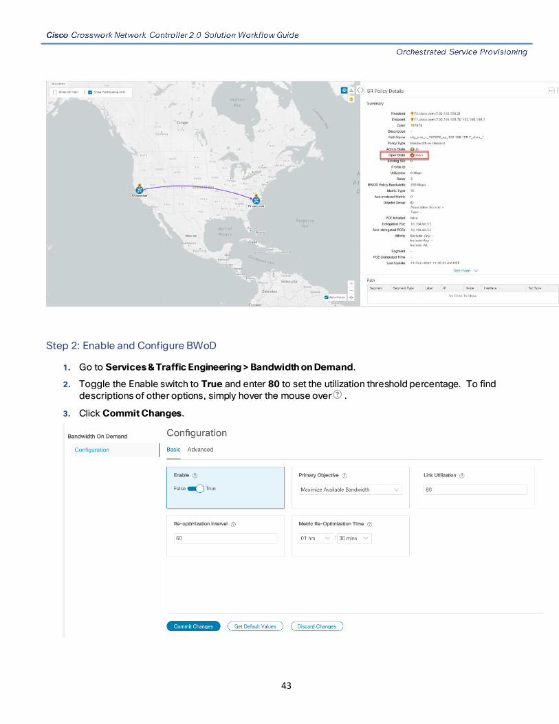
Step 2: Enable and Configure BWoD
1. Go to Services & Traffic Engineering > Bandwidth on Demand.
2. Toggle the Enable switch to True and enter 80 to set the utilization threshold percentage. To find descriptions of other options, simply hover the mouse over .
3. Click Commit Changes.

44
Step 3: Verify that the policy’s operational state is now Up and view the path on the map
1. Go to Services & Traffic Engineering > Provisioning.
2. In the Policy table, locate and select the path computed for the endpoints.
3. The path is shown as an overlay on the map. Check the Show IGP Path check box to see the physical path between the endpoints.
Summary and Conclusion
Operators can set and maintain bandwidth requirements based on optimization intent using the BWoD functionality provided in Cisco Crosswork Network Controller. This scenario illustrated how to provision an SR-TE policy with a specific bandwidth request. We saw how to enable BWoD functionality so that traffic is rerouted automatically to maintain bandwidth requirements. This automation alleviates the task of manually tracking and configuring paths to accommodate bandwidth requirements set by SLAs.

45
3 Bandwidth and Network Optimization
Overview
Objective
Tactically optimize the network during times of congestion in real-time.
Challenge
Network congestion leads to poor end-customer experiences. If you have poor connections, slow streaming video, and packet loss, your users will be dissatisfied, which leads to a poor perception of your service in the marketplace. In the worst-case scenario, your network problems lead to service level agreement (SLA) or contract violations and the loss of your brand equity. Network operators need a toolset to help automate bandwidth optimization and efficiently steer traffic with little operator intervention.
Solution
Cisco Crosswork Network Controller provides local congestion mitigation (LCM) as a solution for bandwidth management and congestion mitigation. This is enhanced functionality introduced in Cisco Crosswork Network Controller 2.0.
Local Congestion Mitigation (LCM)
Instead of optimizing for bandwidth resource in the network by rerouting traffic in the entire network (end-to-end path optimization), LCM checks the capacity locally, in and around the congested area, at an interface level and reroutes traffic between the endpoints of the congested interface (local interface-level optimization). Focusing on the problem locally eliminates the need for simulating edge-to-edge traffic flows in the network through a full traffic matrix which is both cumbersome to create and is less scalable as node counts continue to increase.
LCM provides recommendations to divert the minimum amount of traffic away from the congested interface to bring it out of congestion. LCM performs the collection of SR-TE policy and interface counters via SNMP. It estimates the amount of traffic that may be diverted and, if the user approves, performs the mitigation through the deployment of Tactical Traffic Engineering (TTE) SR-TE policies. Mitigating congestion locally does not require the use of the full Segment Routing Traffic Matrix (SR-TM) and TTE SR-TE policies are created only at the device on either side of the congested link, with the shortest paths possible that do not congest interfaces elsewhere.
How Does LCM Work?
1. LCM analyzes the Cisco Crosswork Optimization Engine Model (a real-time topology and traffic representation of the physical network) on a regular cadence. This cadence can be configured but should be greater than or equal to SNMP polling (5 mins).

46
2. In the following example, during one of its polling checks, LCM detects congestion when Node 2 utilization goes above the 70% utilization threshold.
3. LCM calculates how much traffic is eligible to divert.
LCM only diverts traffic that is not already routed by an existing SR-TE policy (for example, unlabeled, IGP-routed, or carried via FlexAlgo-0 SIDs). The traffic within an SR-TE policy will not be included in LCM calculation and will continue to travel over the original programmed path.
Eligible traffic is computed by taking the interface traffic statistics that account for all traffic on the interface and subtracting the sum of traffic statistics for all SR-TE policies that flow over the interface.
Total interface traffic – SR-TE policy traffic = Eligible traffic that can be optimized
This process must account for any ECMP splitting of SR-TE policies to ensure the proper accounting of SR-TE policy traffic. In this example, the total traffic on congested Node 2 is 800 Mbps. The total traffic of all SR-TE policies routed over Node 2 is 500 Mbps. The total traffic that LCM can divert in this example is 300 Mbps:
800 Mbps – 500 Mbps = 300 Mbps
4. LCM calculates the amount of traffic that must be sent over alternate paths by subtracting the threshold equivalent traffic from the total traffic on the interface. In this example, the amount to be diverted is 100 Mbps:
800 Mbps – 700 Mbps (70% threshold) = 100 Mbps
LCM must route 100 Mbps of 300 Mbps (eligible traffic) to another path.
5. LCM determines how many TTE SR-TE policies are needed and their paths. The ratio of how much LCM eligible traffic can stay on the shortest path to the amount that must be rerouted, will determine the number of TTE SR-TE policies that are needed on the shortest versus alternate paths, respectively.
In this case, LCM needs to divert 1/3 of the total eligible traffic (100 Mbps out of 300 Mbps) away from the congested link. Assuming a perfect ECMP, LCM estimates that 3 tactical SR-TE policies are required to create this traffic split: 1 tactical SR-TE policy will take the diversion path and 2 tactical SR-TE Policies will take the original path. There is sufficient capacity in the path between Node 2 and Node 4.

47
Therefore, LCM recommends 3 TTE SR-TE policies (each expected to route approximately 100 Mbps) to be deployed from Node 2 to Node 3 via SR-PCE:
— 2 TTE SR-TE policies to take a direct path to Node 3 (200 Mbps)
— 1 TTE SR-TE policy takes a path via Node 4 (100 Mbps)
These recommendations will be listed in the LCM Operational Dashboard.
Assuming you deploy these TTE SR-TE policies, LCM continues to monitor the deployed TTE policies and will recommend modifications or deletions as needed in the LCM Operational Dashboard. TTE SR-TE policy removal recommendations will occur if the mitigated interface would not be congested if these policies were removed, minus a hold margin. This helps to avoid unnecessary TTE SR-TE policy churn throughout the LCM operation.
Usage Scenarios
We will walk you through the following usage scenario that illustrates the execution of bandwidth-constrained optimization and LCM:
Scenario 5 – Use Local Congestion Mitigation (LCM) to reroute traffic on an over-utilized link
Additional Resources
Cisco Crosswork Optimization Engine Documentation
Scenario 5 – Use Local Congestion Mitigation (LCM) to reroute
traffic on an over-utilized link
Scenario Context
In this scenario, we will enable LCM and observe the congestion mitigation recommendations to deploy TTE policies when utilization on a device’s interfaces surpasses the defined utilization threshold. We will preview the recommended TTE policies before committing them to mitigate the congestion.

48
This example uses the following topology:
We will observe the actions taken when the link between PE1-ASR9k and P1-ASR9k becomes over-utilized. Note that there is currently no indication of congestion on that link.
Assumptions and Prerequisites
The following is a non-exhaustive list of high-level requirements for proper LCM operation:
Congestion Evaluation
LCM requires traffic statistics from the following:
■ SNMP interface traffic measurements
■ SNMP headend SR-TE policy traffic measurements
Congestion Mitigation
■ The headend device must support PCE-initiated SR-TE policies with autoroute steering.
■ The headend device must support Equal Cost Multi-Path (ECMP) across multiple parallel SR-TE policies.
As an example, the Cisco ASR 9000 is a platform that fulfills all requirements and is supported in Crosswork Network Controller 2.0. For more information, please contact your Cisco Account representative.

49
Workflow
■ Step 1: Enable LCM and configure the utilization threshold
■ Step 2: View link congestion on the map
■ Step 3: View TTE SR-TE policy recommendations in the LCM dashboard
■ Step 4: Validate the TTE SR-TE policy deployment
■ Step 5: Remove the TTE SR-TE policies upon LCM recommendation
Step 1: Enable LCM and configure the utilization threshold
1. Go to Services & Traffic Engineering > Local Congestion Mitigation > Configuration .
2. Toggle the Enable switch to True and enter the global utilization threshold you want to set. In this case, the threshold is set at 25%. To see information other configuration options, simply hover the mouse over
.
3. Click Commit Changes.
Step 2: View link congestion on the map
The link between PE1-ASR9k and P1-ASR9k is now congested. Let’s see that on the map.
1. Go to Services & Traffic Engineering > Traffic Engineering. Note that the link is Orange, indicating higher utilization.

50
2. Click on the link to view link details, including utilization information. Note that utilization on the PE1-ASRk interfaces has surpassed 25%, the threshold that was defined in the LCM configuration.
Step 3: View TTE SR-TE policy recommendations in the LCM dashboard
LCM has detected the congestion and computed tactical policies to mitigate the congestion which we can preview and then decide whether or not to commit them.
1. Go to Services & Traffic Engineering > Local Congestion Mitigation > LCM Operational Dashboard.
In this case, the dashboard also shows that the utilization on the PE1-ASRk interfaces has surpassed 25%. In the Recommended Action column, there is a recommendation to deploy 2 TTE policy solution sets to address the congestion. The Expected Util column shows the expected utilization of the interface if the recommended action is committed.

51
2. To preview the recommended TTE policies, click … in the Actions column and choose Preview. You will see a list of TTE policies for the node and a specific interface, in this case, GigabitEthernet0/0/0/4. Select a TTE policy to see its representation on the map.
3. After you are done viewing the recommended TTE policies on the map, click Back to LCM Dashboard.
4. If you are satisfied with the LCM recommendations, click Commit All. The LCM State column changes to Mitigating. Note that all LCM recommendations must be committed in order to mitigate congestion and produce the expected utilization as shown in the LCM Dashboard. The mitigation solution is based on all LCM recommendations being committed because of dependencies between solution sets.

52
Step 4: Validate the TTE SR-TE policy deployment
1. in the top right corner
2. You can also view the LCM Dashboard to check that the LCM state changes to Mitigated for all TTE policy solution sets.
3. Confirm the TTE policy deployment visually on the topology map and in the SR-TE policy table.
a. Go to Services & Traffic Engineering > Traffic Engineering > SR-TE tab.
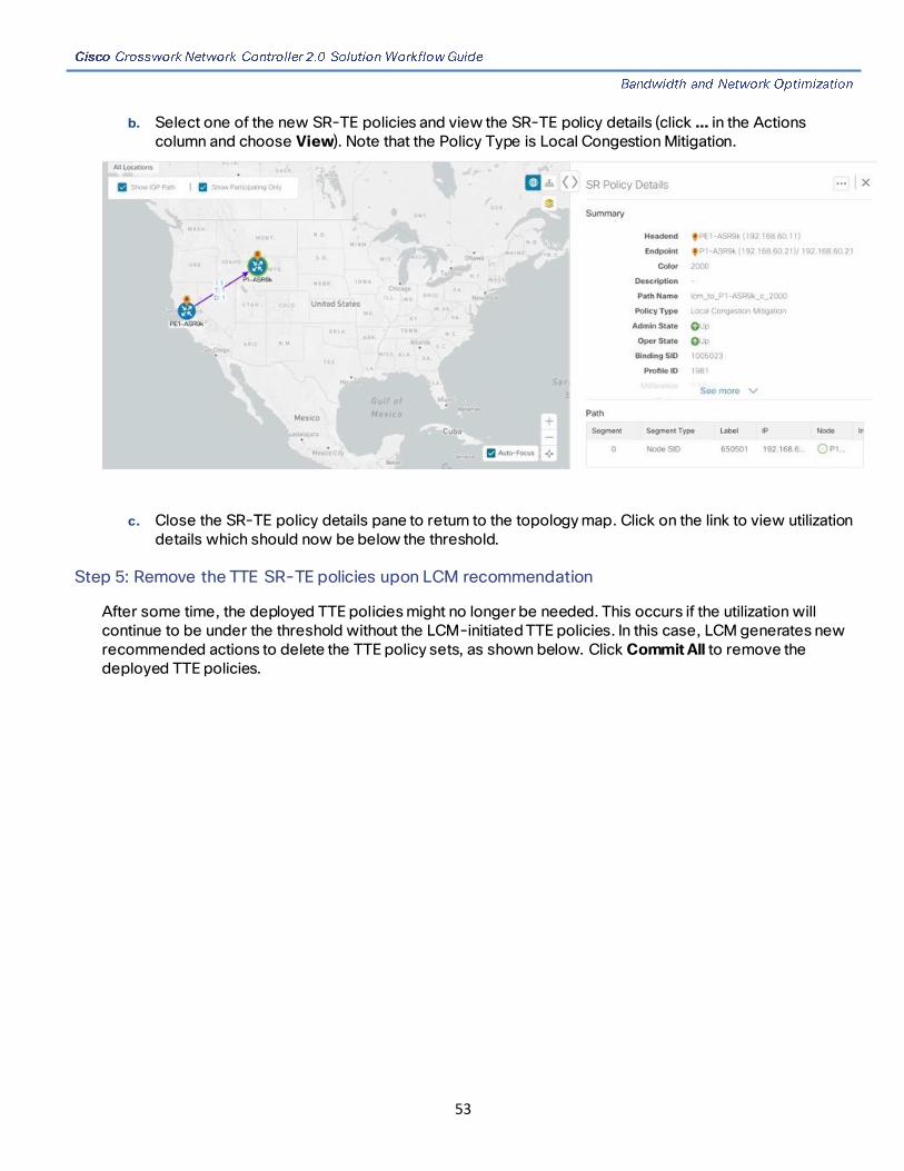
53
b. Select one of the new SR-TE policies and view the SR-TE policy details (click … in the Actions column and choose View). Note that the Policy Type is Local Congestion Mitigation.
c. Close the SR-TE policy details pane to return to the topology map. Click on the link to view utilization details which should now be below the threshold.
Step 5: Remove the TTE SR-TE policies upon LCM recommendation
After some time, the deployed TTE policies might no longer be needed. This occurs if the utilization will continue to be under the threshold without the LCM-initiated TTE policies. In this case, LCM generates new recommended actions to delete the TTE policy sets, as shown below. Click Commit All to remove the deployed TTE policies.

54
Summary and Conclusion
In this scenario we observed how to leverage LCM to alleviate traffic congestion in the network. LCM takes the manual tracking and calculation out of your hands but at the same time gives you control as to whether to implement the congestion mitigation recommendations or not. You can preview the recommendations and see how the potential deployment will take effect in your network before you deploy them. As traffic changes, LCM tracks the deployed TTE SR-TE policies and decides whether or not they are still needed. If not, LCM recommends deleting them.
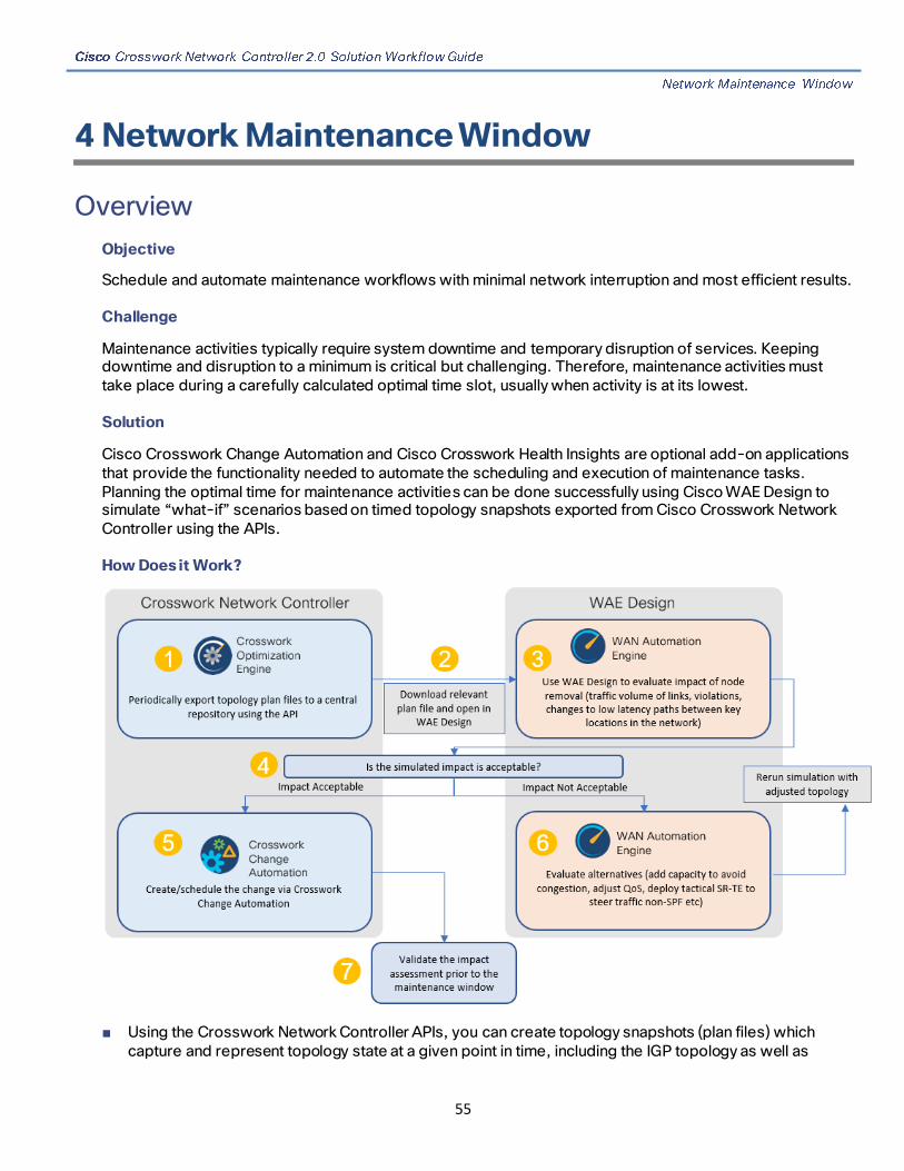
55
4 Network Maintenance Window
Overview
Objective
Schedule and automate maintenance workflows with minimal network interruption and most efficient results.
Challenge
Maintenance activities typically require system downtime and temporary disruption of services. Keeping downtime and disruption to a minimum is critical but challenging. Therefore, maintenance activities must take place during a carefully calculated optimal time slot, usually when activity is at its lowest.
Solution
Cisco Crosswork Change Automation and Cisco Crosswork Health Insights are optional add-on applications that provide the functionality needed to automate the scheduling and execution of maintenance tasks. Planning the optimal time for maintenance activities can be done successfully using Cisco WAE Design to simulate “what-if” scenarios based on timed topology snapshots exported from Cisco Crosswork Network Controller using the APIs.
How Does it Work?
■ Using the Crosswork Network Controller APIs, you can create topology snapshots (plan files) which capture and represent topology state at a given point in time, including the IGP topology as well as

56
interface level statistics (traffic load). For impact analysis purposes, these snapshots should be representative of a time period to be evaluated for an upcoming maintenance activity. For example, if you are planning a router upgrade at midnight on a Monday, you would take snapshots from several Mondays at midnight to evaluate typical traffic loads at this time. You can export these plan files to a central storage repository, where a library of topology plan files can be stored for a specified period of time.
■ Cisco WAE Design allows you to explore “what-if” scenarios relevant to the planning of the maintenance window. For example, in the case of upgrading a router, Cisco WAE Design can simulate the resulting traffic load on the remaining devices once traffic is diverted from the device being upgraded. You can also explore the impact of deploying tactical traffic engineering policies to further optimize the topology during the maintenance window. For more information, contact your Cisco Customer Experience representative.
Usage Scenarios
Scenario 6: Perform a software upgrade on a provider device during a scheduled maintenance window
Additional Resources
Cisco Crosswork Change Automation and Health Insights User Guide
Cisco WAE Design documentation
Cisco Crosswork Network Automation API Documentation on Cisco Devnet
Scenario 6: Perform a software upgrade on a provider device
during a scheduled maintenance window
Scenario Context
This scenario assumes that Cisco WAE Design has been used to evaluate the impact of removing a P node from the network to perform a software upgrade during a specific timeframe. In this scenario, we will choose a predefined playbook to automate the execution of the SMU on the device, and we will schedule it to run during the predetermined maintenance window.
Assumptions and Prerequisites
■ Cisco Crosswork Change Automation must be installed and running.
■ You must have access to Cisco WAE Design.
■ The Device Override Credentials must be set for Crosswork Network Change Automation to be functional. Go to Administration > Settings > System Settings > Network Automation.
Workflow
■ Step 1: Download Topology Plan Files for Impact Analysis
■ Step 2: Schedule and execute the SMU by running a playbook

57
■ Step 3: Verify the SMU install job completion status
Step 1: Download Topology Plan Files for Impact Analysis
When considering when to take down a device for maintenance so that there will be the least impact to the network, you need information about the traffic trends around that device at the targeted time. Using the Cisco Crosswork Optimization API, you can download plan files that capture a snapshot of the network topology at that time. If you download plan files at the same time over a period of time, you can use Cisco WAE Design to analyze the traffic trends. Based on this analysis, you can decide whether the impact to the network would be acceptable or not.
Refer to Cisco Crosswork Network Automation API Documentation on Cisco Devnet for more information about the API.
Procedure
1. Prepare the input required to download the plan file. You need to specify the version of Cisco WAE design that you will be using for analysis and the format in which you want the plan file, either txt or pln.
Note: If you download the plan file as a txt file, you can view it in any text editor. If you download it as a pln file, you can open it only in Cisco WAE design.
The input for this scenario is as follows:
'{ "input": { "version": "7.3.1", "format": "txt",
} } }'
2. Invoke the API on the Cisco Crosswork Network Controller server using the input prepared in the previous step. For example:
curl --location --request POST 'https://10.194.63.198:30603/crosswork/nbi/optima/v1/restconf/operations/cisco-crosswork-optimization-engine-operations:get-plan \ --header 'Content-Type: application/yang-data+json' \ --header 'Accept: application/yang-data+json' \ --header 'Authorization: Bearer eyJhbGciOiJIUzUxMiJ9.eyJzdWIiOiJhZG1pbiIsImlzRnJvbU5ld0xvZ2luIjoidHJ1ZSIsInBvbGljeV9pZCI6ImFkbWluIiwiYXV0aGVudGljYXRpb25EYXRlIjoiMjAyMS0wMy0yMlQxNjozODozNy43NDY2MTZaW0dNVF0iLCJzdWNjZXNzZnVsQXV0aGVudGljYXRpb25IYW5kbGVycyI6IlF1ZXJ5RGF0YWJhc2VBdXRoZW50aWNhdGlvbkhhbmRsZXIiLCJpc3MiOiJodHRwOlwvXC9sb2NhbGhvc3Q6NTQ4OVwvU1NPIiwibGFzdF9uYW1lIjoic21pdGgiLCJjcmVkZW50aWFsVHlwZSI6IlVzZXJuYW1lUGFzc3dvcmRDcmVkZW50aWFsIiwiYXVkIjoiaHR0cHM6XC9cLzEwLjE5NC42My4xOTg6MzA2MDNcL2FwcC1kYXNoYm9hcmQiLCJhdXRoZW50aWNhdGlvbk1ldGhvZCI6IlF1ZXJ5RGF0YWJhc2VBdXRoZW50aWNhdGlvbkhhbmRsZXIiLCJsb25nVGVybUF1dGhlbnRpY2F0aW9uUmVxdWVzdFRva2VuVXNlZCI6ImZhbHNlIiwiY2hhbmdlX3B3ZCI6ImZhbHNlIiwiZXhwIjoxNjE2NDU5OTIwLCJpYXQiOjE2MTY0MzExMjAsImZpcnN0X25hbWUiOiJqb2huIiwianRpIjoiU1QtODQtOFVlWXMybEt3R2d1Z3RIYjl4MzVmTFlNTGVVRlp6OURyNGpoeFcxakhsV01VYXdXSWgxbUdTd01aRC1tOEk1S2Z0amI2ZmlWTUhlYnBYYjBMMFZqRFc2WVppUFVUbHRpNFVpZnNUeG9aQ284WWpPWEc2VlFjS0Mwb29lWjJhc3BWanMzYnA3bHo5VkhySlBCTzl5TDNGcFRIWXRPeWJtVi1jYXMtMSJ9.Vi4k0w8KsOv5M_O8zBqWochT3k9V9Pn2NjSn5ES9c5Pf-4ds0o4kk6xuZx5_cggauiEICuUMnzmRzneST-oAuA' \ --data-raw '{ "input": {

58
"version": "7.3.1", "format": "txt", " } } }'
3. Note the plan file content in the API response. It is encoded for security purposes and must be decoded before you can view the content.
{ "cisco-crosswork-optimization-engine-operations:output": { "status": "accepted", "plan-file content": " PE5ldHdvcms+ClByb3BlcnR5CVZhbHVlClRpdGxlCQpWZXJzaW9uCTcuMy4xCgo8TmV0d29ya09wdGlvbnM+Ck9wdGlvbglWYWx1ZQpFbmZvcmNlQWRqU0lETG9jYWxpemF0aW9uCVRSVUUKCjxDaXJjdWl0cz4KTmFtZQl<<<>>>Ob2RlQQlJbnRlcmZhY2VBCU5vZGVCCUludGVyZmFjZUIJQ2FwYWNpdHkJRGVsYXkJRGlzdMJTmV0SW50U05NUF9FcnJvcglOZXRJbnRTb3VyY2UJTmV0SW50UkUwQ1BVMW0JTmV0SW50UkUwQ1BVNWZpZXIJQWxnb3JpdGhtCVJmbGFnCU5mbGFnCVBmbGFnCUVmbGFnCVZmbGFnCUxmbGFnCg==" } }
4. Use a script to decode the plan file or copy the plan file content into a decoder. After decoding the plan file, you can see the content of the model to be used in Cisco WAE Design. It includes a full snapshot of the topology, including the devices, interfaces, links, LSPs, traffic levels, and other information.
5. Open the plan file in Cisco WAE Design, simulate the device going down, and observe the impact on the network. Refer to the Cisco WAE Design documentation for more information.
6. Based on the analysis, decide on a good time to execute the SMU.
Step 2: Schedule and execute the SMU by running a playbook
If the simulated impact is acceptable, you can create and schedule the change by running a playbook via Cisco Crosswork Change Automation. For this scenario, we will run a predefined playbook to install a Software Maintenance Update (SMU) on devices tagged under a certain geographic location (NY).
Note: If the predefined (stock) plays and playbooks do not meet your specific needs, you can create custom plays and playbooks. To create a custom play, go to Network Automation > Play List and to create a custom playbook, go to Network Automation > Playbook List.
1. Go to Network Automation > Run Playbook.
2. Browse the Available Playbooks list and click the Install a SMU playbook. You can also filter using keywords to identify the playbook. Note that the playbook execution stages, supported software platform, software version, and individual play details are displayed on the right side.
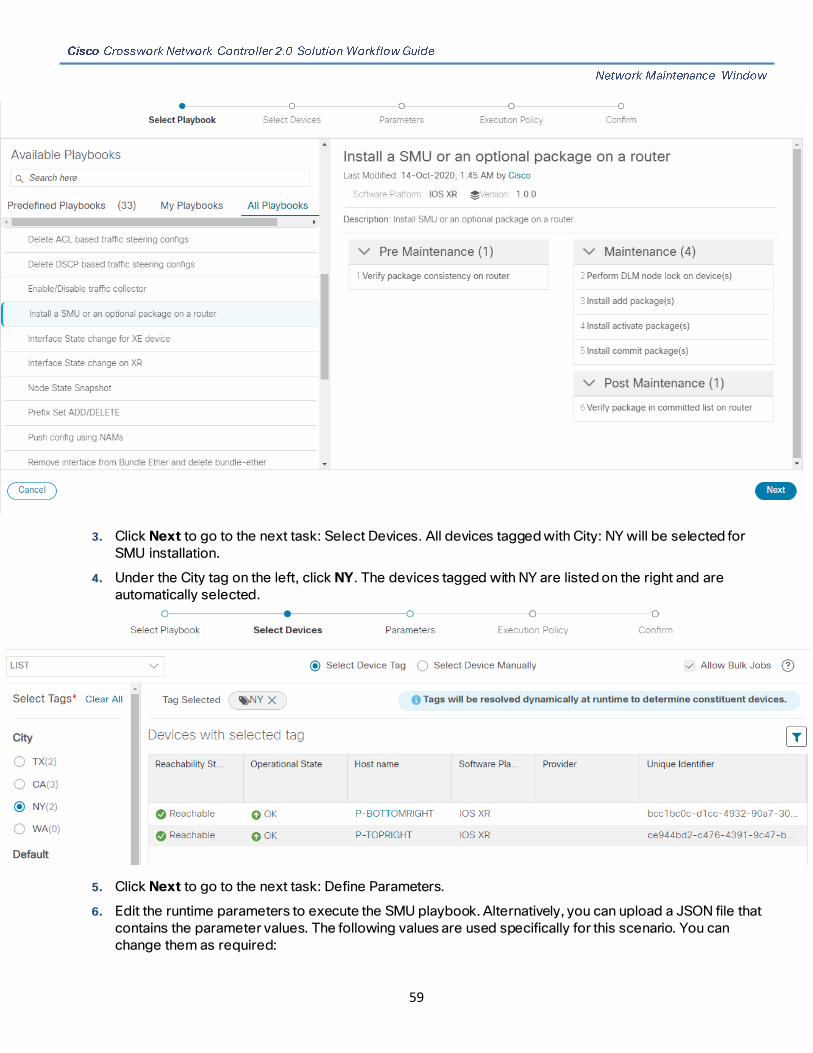
59
3. Click Next to go to the next task: Select Devices. All devices tagged with City: NY will be selected for SMU installation.
4. Under the City tag on the left, click NY. The devices tagged with NY are listed on the right and are automatically selected.
5. Click Next to go to the next task: Define Parameters.
6. Edit the runtime parameters to execute the SMU playbook. Alternatively, you can upload a JSON file that contains the parameter values. The following values are used specifically for this scenario. You can change them as required:

60
a. Under “verify package consistency on the device” play, set collection_type as mdt.
b. Under “perform DLM node lock on device” play, set retry_count and retry_interval as 3 and 5s respectively.
c. Under “Install add package(s)” play, set action as add, and optimize as false. Enter the <SMU package name> in item 1 and set region as NODES.

61
d. Set type as SCP, and enter values for the source, address, destination, and dlm_credential_profile.
e. Under Install activate package(s), click , select action, and set action to Activate.
f. Under Install commit package(s), set action to Commit.
g. Under Verify package in committed list on router, set collection_type to mdt, and enter the <SMU package name> in item 1.

62
7. Click Next to go to the next task: Define Execution Policy.
8. Select Continuous as the Execution mode so that the playbook will run uninterrupted with no pauses. Under Failure policy, select the action you want taken if the execution fails – abort or rollback.
9. Schedule the execution for the optimal time calculated during the impact analysis stage. Uncheck the Run Now option. Note the calendar and timer that are displayed to schedule pre-check and perform plays. Select the date and time for the scheduled maintenance.

63
10. Click Next to go to the next task: Confirm Job.

64
11. Review your job details. Label your job with a unique name. Click Run Playbook. The SMU installation is now scheduled to run in the planned maintenance window.

65
Step 3: Verify the SMU install job completion status
1. After the scheduled maintenance window time, go to Network Automation > Automation Job History. Under Job Sets, check that the job status icon on the SMU install job is Green, indicating that the scheduled job has run successfully.
2. Select the SMU install job. Note the Job Set details on the right side. Click the Execution ID for job details.

66
3. Double-check that the correct SMU has been installed by executing the “show install active summary” and “show install committed summary” commands on the device and checking that the SMU you installed appears in the list. Some example outputs from these commands are shown below:
Summary and Conclusion
In this scenario we saw how to plan for a maintenance window in which to bring down a device in order to install an SMU. The goal is to cause as little impact to the traffic in the network as possible. To analyze the impact on the network, we showed how to download snapshots of the network topology (plan files) at the target time for the maintenance window. The plan files can then be analyzed using Cisco WAE design. Assuming that the impact was acceptable, we chose a predefined playbook to install the SMU on specific devices and we scheduled it for the planned maintenance window time when there would be the least impact to the network.

67
5 Programmable Closed-Loop Auto-Remediation
Overview
Objective
Detect anomalies and generate alerts that can be used for notifying an operator or triggering automation workflows.
Challenge
Discovering and repairing problems in the network usually involves manual network operator intervention and is time-consuming and error prone.
Solution
Incorporating Cisco Crosswork Change Automation and Cisco Crosswork Health Insights into Cisco Crosswork Network Controller gives service providers the ability to automate the process of discovering and remediating problems in the network by allowing an operator to match an alarm to pre-defined remediation tasks. These tasks will automatically be performed once a defined Key Performance Indicator (KPI) threshold has been breached. Remediation can be implemented with or without the network operator ’s approval, depending on the setting and preferences of the operator.
Using such closed-loop remediation reduces the time taken to discover and repair a problem while minimizing the risk of making a mistake and creating an additional error through high-stakes manual network operator intervention.
How Does it Work?
Smart Monitoring
■ Zero-touch telemetry streamlines the operational and network management overhead of collecting and cleansing data, thereby allowing operators to focus on their business goals. As part of zero-touch telemetry, devices are automatically provisioned with telemetry configuration and tables/schema are created in a Time Series Database (TSDB).
■ By using a common collector to collect network device data over SNMP, CLI, and model-driven telemetry, and making it available as modelled data described in YANG, duplicate data collection is avoided, optimizing the load on both the devices and the network.
■ Recommendation Engine analyzes network device hardware and software, configuration, and employs a pre-trained model built from data mining, producing KPI relevant recommendations facilitating per use-case monitoring.
■ KPIs cover a wide range of statistics from CPU, memory, disk, layer 1/2/3 network counters, to per protocol, LPTS and ASIC statistics.
Smart Filtering
■ Cisco Crosswork Health Insights builds dynamic detection and analytics modules that allow operators to monitor and see alerts on network events based on user-defined logic (KPI).
■ Key Performance Indicators (KPIs) Alerting Logic can be :

68
— Simple static thresholds (TCA), e.g., CPU load going above 90 percent.
— Moving average, standard-deviation, and percentile based, etc., e.g., CPU load above mean and staying there for five minutes.
— Streaming jobs which provide real-time alerts or batch jobs which run periodically.
— Customized for threshold values and visualization dashboards.
— Customized operator-created KPIs based on business logic (easily scripted with a domain specific language).
— TCAs can be exported/integrated with other systems via HTTP, Slack and socket interfaces.
■ KPIs can be associated with dashboards, which provide real-time and historical views of the raw data and corresponding TCAs.
■ KPIs also provide purpose-built dashboards that go beyond raw data and provide valuable information in various infographic style charts and graphs useful for triaging and root-causing complex issues
Smart Remediation
■ Health Insights KPIs can be associated with Cisco Crosswork Change Automation (CCCA) playbooks (or webhooks), which can be either executed manually or via auto-remediation. Remediation workflow could be used to fix the issue or collect more data from the network devices. By proactively remediating the situation, instead of resorting to ad hoc debugging and unscheduled downtime, operators can save time and money, providing better QOE to their customers.
■ Health Insights does the correlation of alerts/anomalies on the topology of the network, allowing easy visualization of the impact of events.
Scenario 7 – Achieve Predictive Traffic Load Balancing Using
Segment Routing Affinity
Scenario Context
To maintain smooth and optimal traffic flow, operators need to be able to monitor traffic on the interfaces, identify errors such as CRC, watch dog, overrun, and then reroute the traffic so that the SLA is maintained. This process can be automated using Cisco Crosswork Network Controller with Cisco Crosswork Health Insights and Cisco Crosswork Change Automation applications installed.
Assumptions and Prerequisites
Cisco Crosswork Health Insights and Cisco Crosswork Change Automation must be installed and running.
Workflow
Following is a high-level workflow for executing this scenario:
1. Deploy Day0 ODN templates on edge nodes with dynamic path calculation delegated to SR-PCE and the ODN template configured to exclude links that are tagged with a specific affinity, for example, RED affinity. ODN allows a service head-end router to automatically instantiate an SR-TE policy to a BGP

69
next-hop when required (on-demand). The ODN template defines the required SLA using a specific color.
For an example procedure for creating an ODN template, refer to Step 1: Create an ODN template to map color to an SLA objective and constraints in Scenario 1 - Implement and Maintain SLA for an L3VPN Service (using ODN).
2. Create an L3VPN route policy to specify the prefixes to which the SLA applies and mark them with the same color used in the ODN template. When traffic from the specified network with a matching color is received, paths are computed based on the SLA defined in the ODN template.
For an example procedure for creating a route policy, refer to Step 1: Create an ODN template to map color to an SLA objective and constraints in Scenario 1 - Implement and Maintain SLA for an L3VPN Service (using ODN).
3. Provision an L3VPN across the required endpoints and create an association between the VPN and the route policy. This makes the connection between the VPN and the ODN template that defines the SLA.
For an example procedure for provisioning an L3VPN, refer to Step 4: Create and provision the L3VPN service in Scenario 1 - Implement and Maintain SLA for an L3VPN Service (using ODN).
4. Define KPIs and continuously monitor the uplink interfaces on the L3VPN endpoints.
For information about defining KPIs, see the Cisco Crosswork Change Automation and Health Insights User Guide.
5. When there is a KPI failure, mark the dirty link with RED affinity so that it will be excluded, based on the specifications of the ODN template. This is achieved by creating a custom playbook. Cisco Crosswork Network Controller learns the name of the interface generating the alert regarding the KPI failure and this is fed into the custom playbook so that the affinity configuration can be pushed to the relevant router, forming a closed-loop automation scenario. In this way, the customer should not experience outages.
For information about defining playbooks, see the Cisco Crosswork Change Automation and Health Insights User Guide.
6. Cisco Crosswork Network Controller continues to monitor the link and when there are no longer KPI failures, the RED affinity tag can be removed. Define another playbook for this purpose.

70
6 Automation of Onboarding and Provisioning of IOS-XR Devices Using ZTP
Overview
Objective
Allow users to quickly, easily, and automatically onboard new devices and provision them using a Cisco-certified software image and a day-zero software configuration.
Challenge
Deploying and configuring network devices is a tedious task. It requires extensive hands-on provisioning and configuration by knowledgeable personnel, which is time-consuming, expensive, and error-prone.
Solution
Automate onboarding of new devices using Crosswork Zero Touch Provisioning (Cisco Crosswork ZTP). Cisco Crosswork ZTP allows users to provision networking devices remotely, without a trained specialist on site. After establishing an entry for the device in the DHCP server and the ZTP application, all the operator needs to do is connect the device to the network, power on and press reset to activate the devices. A certified image, and configuration, are downloaded and applied to the device automatically. Once provisioned in this way, the new device is onboarded to the Crosswork device inventory where it can be monitored and managed like other devices.
How Does it Work?
■ Classic ZTP: The DHCP server verifies the device's identity based on the device's serial number, then offers downloads of the boot file and image. Once the device is imaged, it downloads the configuration file and executes it.
■ Secure ZTP: The device and the Cisco Crosswork ZTP bootstrap server authenticate each other using the device's Secure Unique Device Identifier (SUDI) and Crosswork server certificates over TLS/HTTPS. Once a secure HTTPS channel is established, the Crosswork bootstrap server allows the device to request to download and apply a set of signed image and configuration artifacts adhering to the RFC 8572 YANG schema. Once the image (if any) is downloaded and installed, and the device reloads with the new image, the device downloads configuration scripts and executes them.
Usage Scenarios
Scenario 8 – Automatically onboard and provision new devices in the network
Additional Resources
Detailed information is available in the ZTP chapters in the Cisco Crosswork Infrastructure 4.0 and Applications Administration Guide.

71
Scenario 8 – Automatically onboard and provision new devices
in the network
Scenario Context
With the exponential growth of service provider networks and their rapid expansion into new customer sites and new locations, there is a need to connect an ever-increasing number of edge devices. At the same time, functional sophistication is increasing, requiring more time to configure those devices and activate new services. Manual processes limit a service provider’s ability to rapidly scale networks and roll out new services in a cost-efficient way.
In this scenario, we will onboard the new devices required to set up a new customer site in a remote location and go live, without the need to send skilled technicians on time-consuming and costly on-site visits to complete the provisioning.
We will leverage the configuration of devices at existing customer sites that are already set up and operating to ensure that the day0 configuration of the new devices includes whatever is necessary to get the devices up and running quickly and efficiently.
Assumptions and Prerequisites
■ Crosswork ZTP must be installed in your Cisco Crosswork Network Controller setup.
■ For classic ZTP, Crosswork and the devices must be deployed in a secure network domain.
■ The Crosswork server must be reachable from the devices, via an out-of-band management network or an in-band data network.
■ Cisco NSO must be configured as a Crosswork provider. When configuring the NSO provider, be sure to set the provider property key to forward and the property value to true.
Workflow
This is a high-level workflow for onboarding devices using Cisco Crosswork ZTP. Detailed information is available in the ZTP chapters in the Cisco Crosswork Infrastructure 4.0 and Applications Administration Guide.
■ Step 1: Assemble and upload ZTP assets
■ Step 2: Create a ZTP profile combining an image file and configuration file
■ Step 3: Prepare ZTP device entries for the devices to be onboarded
■ Step 4: Set up DHCP for Crosswork ZTP
■ Step 5: Initiate ZTP processing to onboard the devices
■ Step 6: Monitor the ZTP processing status
■ Step 7: Verify that the onboarded devices appear in the inventory of managed devices
■ Step 8: Add/edit device information if necessary

72
Step 1: Assemble and upload ZTP assets
1. Assemble the following assets before you begin:
— Software images
— Configuration Files
— Credentials of the devices to be onboarded
— Serial numbers of the devices to be onboarded
— Owner certificates (for secure ZTP) - your organization's CA-signed end-entity certificates, installed on your devices and binding a public key to your organization.
— Pinned domain certificate (for secure ZTP) - your organization's CA- or self-signed domain certificate, with its public key pinned to your organization's DNS network domain. The PDC helps your devices verify that images and configurations downloaded and applied during ZTP processing come from within your organization.
— Ownership vouchers (for secure ZTP) - Nonceless audit vouchers that verify that devices being onboarded with ZTP are bootstrapping into a domain owned by your organization. Cisco supplies OVs when a request is submitted with your organization's PDC and device serial numbers.
2. Upload the software images. Go to Device Management > Software Images.
3. Upload the configuration files. Go to Device Management > Configuration Files.
4. Upload device serial numbers. Go to Device Management > Voucher Management and click Add Serial Number.
5. For secure ZTP, upload your pinned domain certificate and owner certificates. Go to Administration > Certificate Management and add your certificates.
6. For secure ZTP, upload ownership vouchers. Go to Device Manager > Voucher Management.
Step 2: Create a ZTP profile combining an image file and configuration file
Crosswork uses ZTP profiles to automate imaging and configuration processes. While optional, creating ZTP profiles is recommended as the best way to combine a single image file and configuration file based on a product or device family, such as the Cisco ASR 9000 or Cisco NCS5500. We recommend that you create only one day-zero ZTP profile for each device family, use case or role the devices serve in the network.
To create ZTP profiles, go to Device Management > ZTP Profiles.
Step 3: Prepare ZTP device entries for the devices to be onboarded
Depending on how many devices you are onboarding, you can either prepare and import a CSV file or you can create device entries individually.
1. Go to Device Management > Devices.
2. Click the Zero Touch Devices tab.

73
Step 4: Set up DHCP for Crosswork ZTP
Before triggering ZTP processing, you must update your organization's DHCP server configuration file with the IDs for your ZTP device entries and the paths to the image and configuration files stored in the ZTP repository. This allows Crosswork and DHCP to identify these ZTP devices and to respond correctly to each device's requests for connection to the network, and to download image and configuration files.
Step 5: Initiate ZTP processing to onboard the devices
Initiate ZTP processing by rebooting each of the devices to be provisioned.
Step 6: Monitor the ZTP processing status
You can monitor the progress of the ZTP processing in the dashboard.
1. Click Home in the main menu and take a look at the Zero Touch Provisioning dashlet.
2. Click on the View ZTP devices link to view the status of individual devices.
Step 7: Verify that the onboarded devices appear in the inventory of managed devices
Step 8: Add/edit device information if necessary
Some of the information needed for a complete device inventory record is either not needed in order to onboard the device, or not directly available via automation. For example, geographical location data defined using a set of GPS coordinates.
ZTP devices, once onboarded, are automatically part of the shared Crosswork device inventory, and can be edited like any other device.