Embed Size (px)
Citation preview
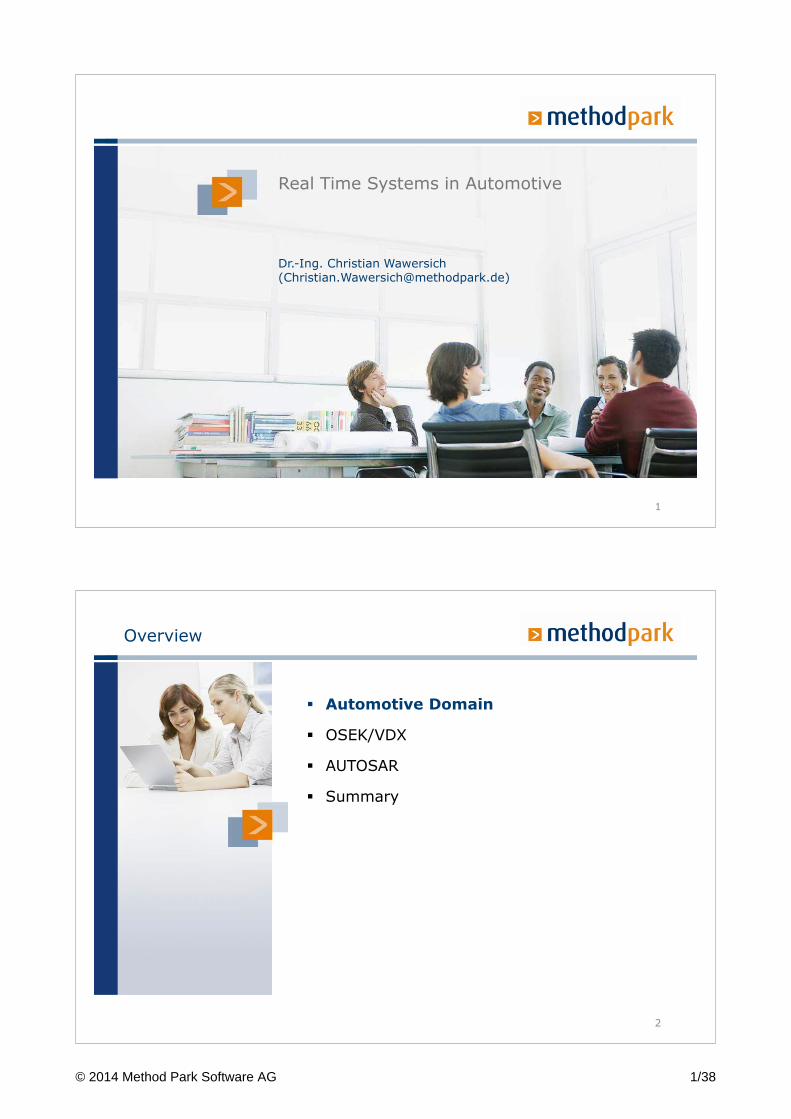
Real Time Systems in Automotive
Dr.-Ing. Christian Wawersich([email protected])
1
Overview
2
� Automotive Domain
� OSEK/VDX
� AUTOSAR
� Summary
© 2014 Method Park Software AG 1/38
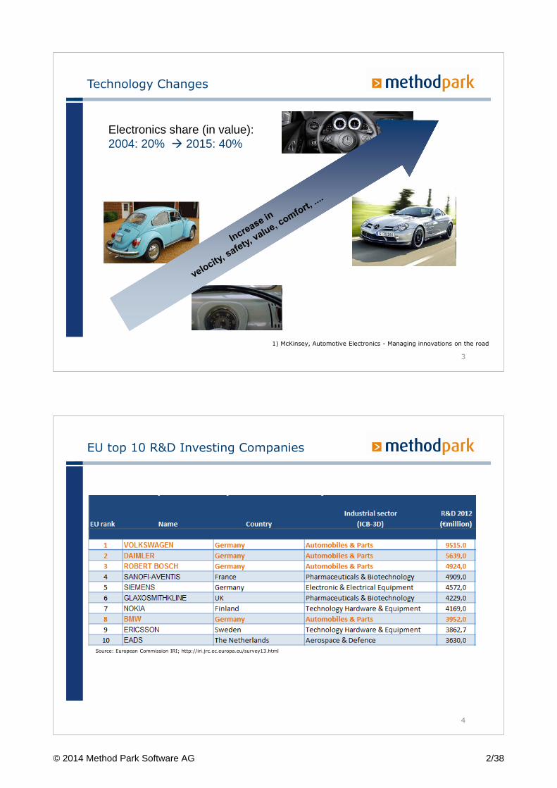
Technology Changes
3
Electronics share (in value): 2004: 20% � 2015: 40%
1) McKinsey, Automotive Electronics - Managing innovations on the road
EU top 10 R&D Investing Companies
4
Source: European Commission IRI; http://iri.jrc.ec.europa.eu/survey13.html
© 2014 Method Park Software AG 2/38
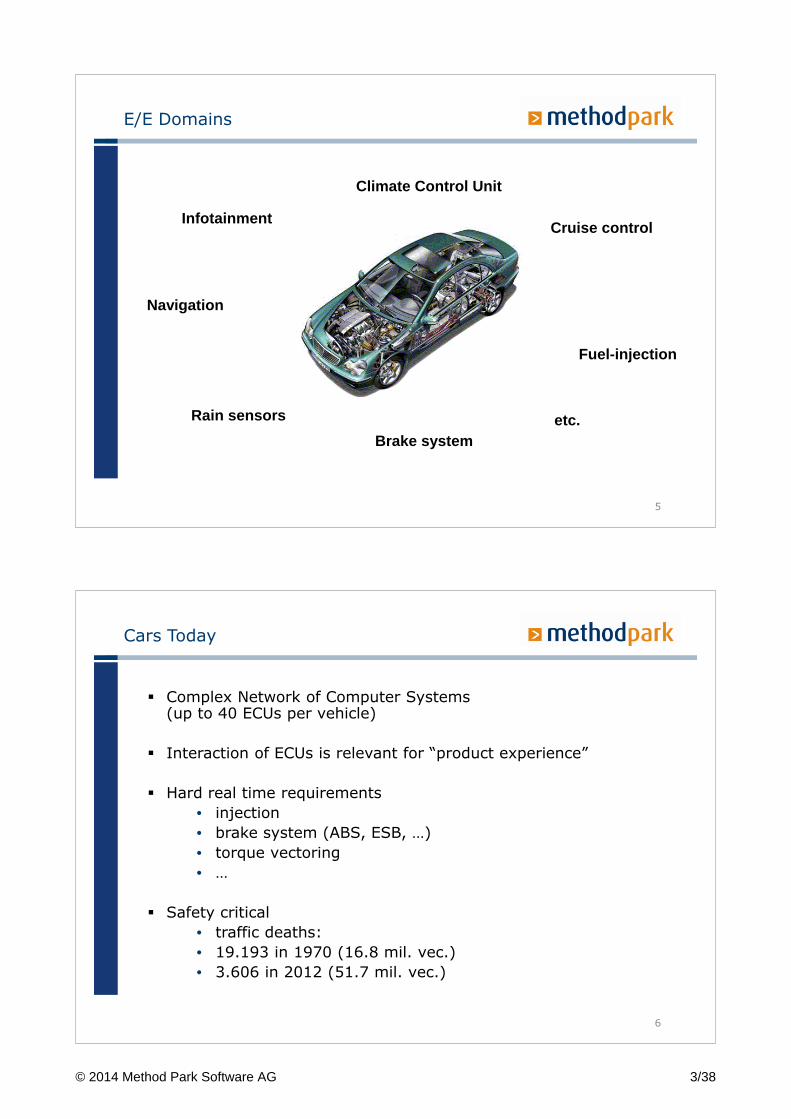
E/E Domains
5
Climate Control Unit
Rain sensors
Infotainment
Fuel-injection
Navigation
Brake system
Cruise control
etc.
Cars Today
� Complex Network of Computer Systems(up to 40 ECUs per vehicle)
� Interaction of ECUs is relevant for “product experience”
� Hard real time requirements
• injection
• brake system (ABS, ESB, …)
• torque vectoring
• …
� Safety critical
• traffic deaths:
• 19.193 in 1970 (16.8 mil. vec.)
• 3.606 in 2012 (51.7 mil. vec.)
6
© 2014 Method Park Software AG 3/38
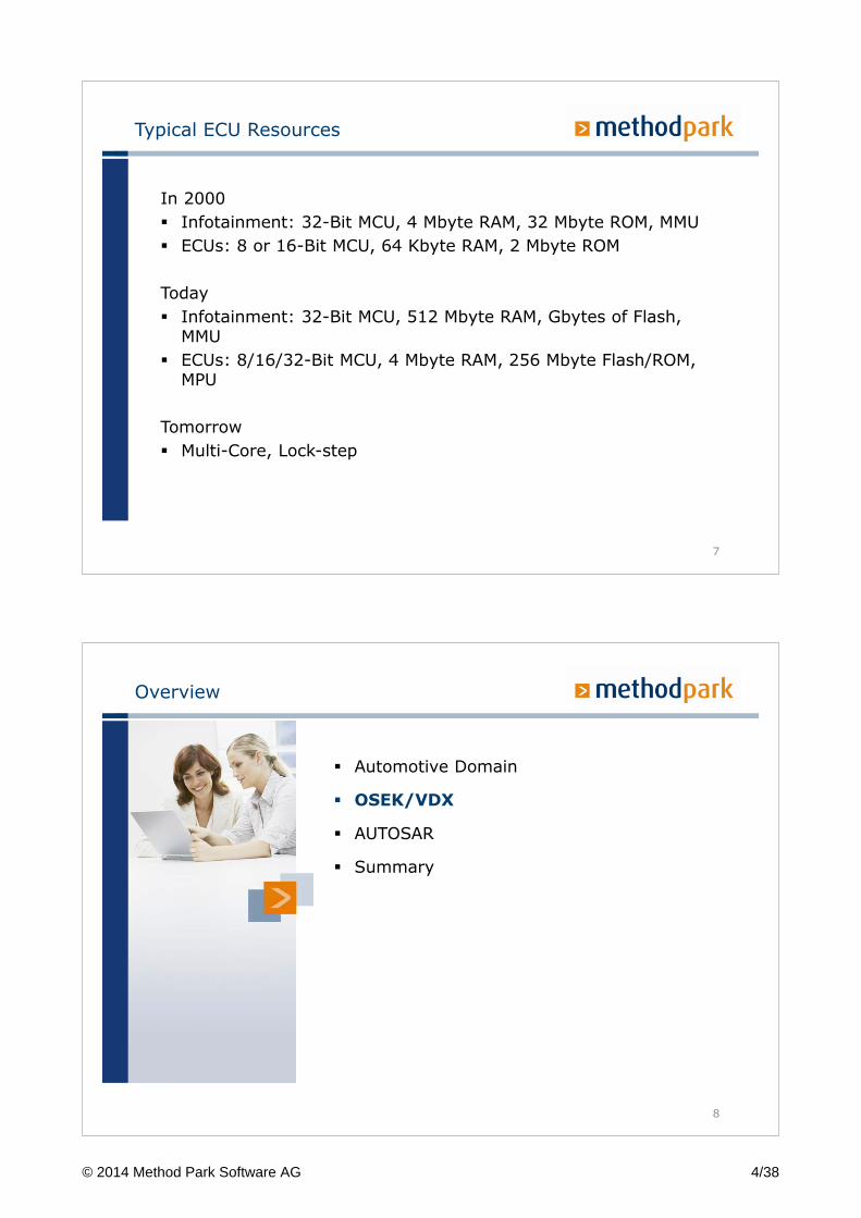
Typical ECU Resources
In 2000
� Infotainment: 32-Bit MCU, 4 Mbyte RAM, 32 Mbyte ROM, MMU
� ECUs: 8 or 16-Bit MCU, 64 Kbyte RAM, 2 Mbyte ROM
Today
� Infotainment: 32-Bit MCU, 512 Mbyte RAM, Gbytes of Flash, MMU
� ECUs: 8/16/32-Bit MCU, 4 Mbyte RAM, 256 Mbyte Flash/ROM, MPU
Tomorrow
� Multi-Core, Lock-step
7
Overview
8
� Automotive Domain
� OSEK/VDX
� AUTOSAR
� Summary
© 2014 Method Park Software AG 4/38
Which OS is used?
Infotainment
� Linux (RT Linux, Android)
� VxWorks
� Windows CE
ECUs
� Infinite main loop (past)
� OSEK/VDX
� AUTOSAR (since 2005)
9
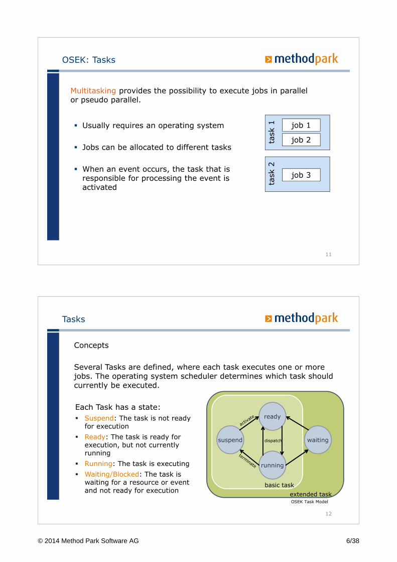
Infinite Loop
Within each loop cycle, a series of jobs is processed sequentially
10
Read sensors
Process data
Control actuators
Perform self test
© 2014 Method Park Software AG 5/38
OSEK: Tasks
� Usually requires an operating system
� Jobs can be allocated to different tasks
� When an event occurs, the task that is responsible for processing the event is activated
Multitasking provides the possibility to execute jobs in parallel or pseudo parallel.
job 1
job 2
job 3
task 1
task 2
11
Tasks
Concepts
Several Tasks are defined, where each task executes one or more jobs. The operating system scheduler determines which task should currently be executed.
12
ready
suspend
running
dispatch waiting
basic task
extended task
Each Task has a state:
� Suspend: The task is not ready for execution
� Ready: The task is ready for execution, but not currently running
� Running: The task is executing
� Waiting/Blocked: The task is waiting for a resource or event and not ready for execution
OSEK Task Model
© 2014 Method Park Software AG 6/38
Flexible Preemption
Preemptable
� A task can be preempted at any time by another task, e.g. because task with higher priority becomes ready
Non-preemptable
� A task always runs to completion
13
Fixed Priority Scheduling
� Each task has a unique priority
� Priorities are assigned at design time
� The operating system ensures that at each time, of all the "ready" tasks the one with the highest priority is executing.
14
© 2014 Method Park Software AG 7/38
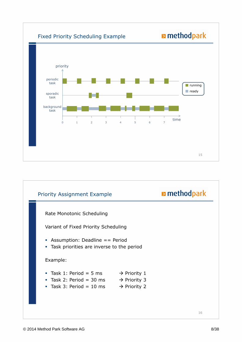
Fixed Priority Scheduling Example
backgroundtask
running
ready
priority
time0 1 2 3 4 5 6 7
periodictask
sporadictask
15
Priority Assignment Example
Rate Monotonic Scheduling
Variant of Fixed Priority Scheduling
� Assumption: Deadline == Period
� Task priorities are inverse to the period
Example:
� Task 1: Period = 5 ms � Priority 1
� Task 2: Period = 30 ms � Priority 3
� Task 3: Period = 10 ms � Priority 2
16
© 2014 Method Park Software AG 8/38
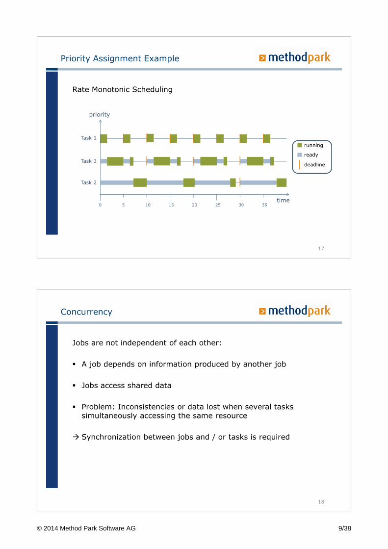
Priority Assignment Example
Rate Monotonic Scheduling
Task 2
running
ready
priority
time0 5 10 15 20 25 30 35
Task 1
Task 3
17
deadline
Concurrency
Jobs are not independent of each other:
� A job depends on information produced by another job
� Jobs access shared data
� Problem: Inconsistencies or data lost when several tasks simultaneously accessing the same resource
� Synchronization between jobs and / or tasks is required
18
© 2014 Method Park Software AG 9/38
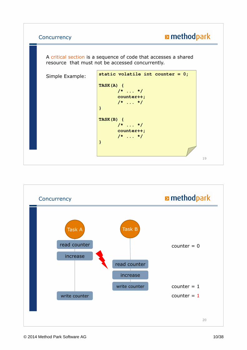
Concurrency
A critical section is a sequence of code that accesses a shared resource that must not be accessed concurrently.
Simple Example:static volatile int counter = 0;
TASK(A) {/* ... */counter++;/* ... */
}
TASK(B) {/* ... */counter++;/* ... */
}
19
Concurrency
read counter
Task A Task B
increase
read counter
write counter
increase
write counter
counter = 0
counter = 1
counter = 1
20
© 2014 Method Park Software AG 10/38
Concurrency
Mutual Exclusion (Mutex) ensures that two tasks are not in their critical section at the same time.
There are several techniques used in embedded systems
� Disable interrupts
� Lock
� Semaphore
� Atomic operations
� Spin-lock
� …
21
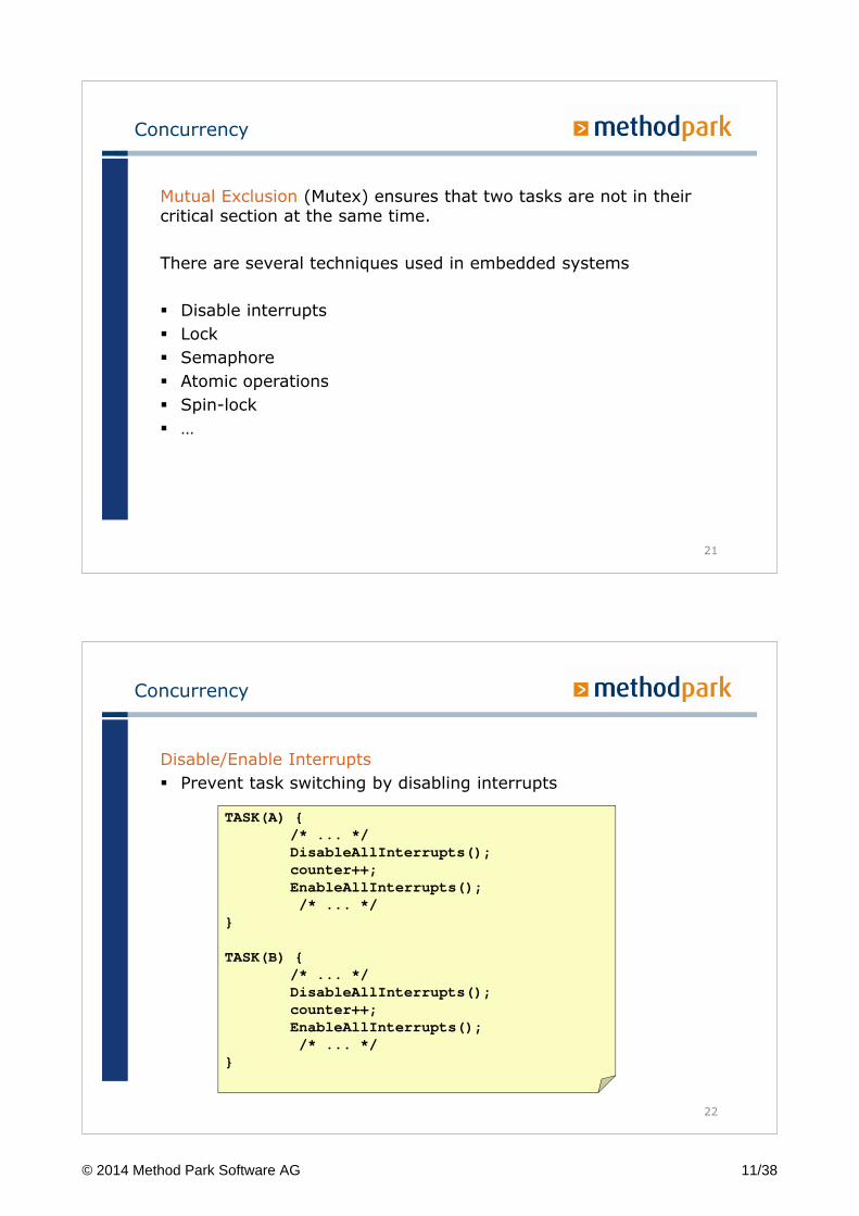
Concurrency
Disable/Enable Interrupts
� Prevent task switching by disabling interrupts
TASK(A) {/* ... */DisableAllInterrupts();counter++;EnableAllInterrupts();/* ... */
}
TASK(B) {/* ... */DisableAllInterrupts();counter++;EnableAllInterrupts();/* ... */
}
22
© 2014 Method Park Software AG 11/38
Concurrency
Disable/Enable Interrupts
Strengths:
� Low overhead on common MCUs
Limitations:
� Error-prone (e.g. missing enable interrupts)
� Increased interrupt latency
� Not suitable for multi-core systems
� Critical section should be kept as short as possible
23
Concurrency
Synchronization Issues:
� Priority Inversion: A task with lower priority is superseding a task with higher priority, even if they do not share a resource
� Deadlock: No progress any more because all tasks are in the waiting state. e.g. two tasks are waiting on each other
24
© 2014 Method Park Software AG 12/38
Concurrency
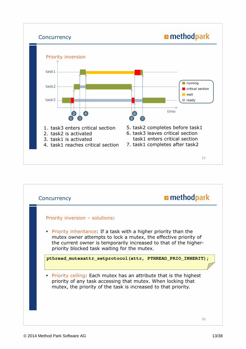
Priority inversion
25
time
task1
task2
task3
running
critical section
ready
wait
1. task3 enters critical section2. task2 is activated3. task1 is activated4. task1 reaches critical section
5. task2 completes before task16. task3 leaves critical section
task1 enters critical section7. task1 completes after task2
1
2
3
4
5 7
6
Concurrency
Priority inversion – solutions:
� Priority inheritance: If a task with a higher priority than the mutex owner attempts to lock a mutex, the effective priority of the current owner is temporarily increased to that of the higher-priority blocked task waiting for the mutex.
� Priority ceiling: Each mutex has an attribute that is the highest priority of any task accessing that mutex. When locking that mutex, the priority of the task is increased to that priority.
pthread_mutexattr_setprotocol(attr, PTHREAD_PRIO_INHERIT);
26
© 2014 Method Park Software AG 13/38
Concurrency
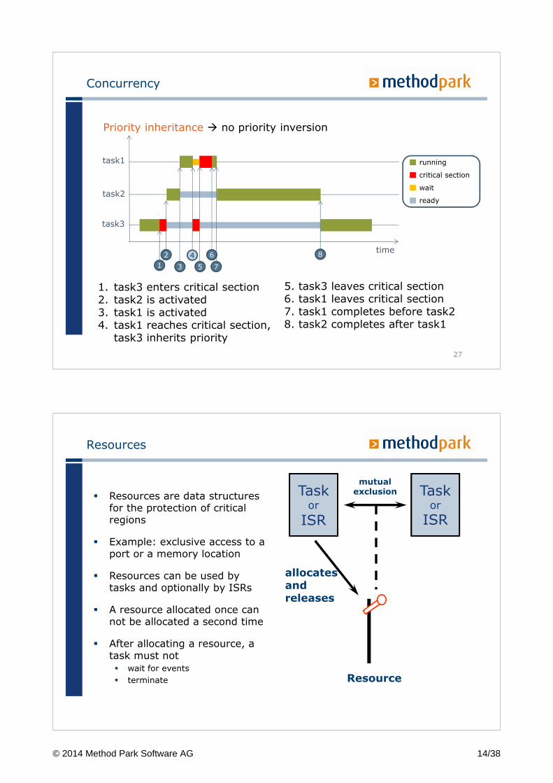
Priority inheritance � no priority inversion
27
time
task1
task2
task3
1. task3 enters critical section2. task2 is activated3. task1 is activated4. task1 reaches critical section,
task3 inherits priority
5. task3 leaves critical section6. task1 leaves critical section7. task1 completes before task28. task2 completes after task1
1
2
3
4
75
8
running
critical section
ready
wait
6
Resources
� Resources are data structures for the protection of critical regions
� Example: exclusive access to a port or a memory location
� Resources can be used by tasks and optionally by ISRs
� A resource allocated once can not be allocated a second time
� After allocating a resource, a task must not
� wait for events
� terminate
Taskor
ISR
Resource
Taskor
ISR
mutualexclusion
allocatesand releases
© 2014 Method Park Software AG 14/38
Resources
Task B
Task A
Resource X
Memory XY
GetResource(X)ReleaseResource(X)
GetResource(X)ReleaseResource(X)
Read / WriteRead / Write
TASK(A){GetResource(ResX);/* access memory XY */ReleaseResource(ResX);}
TASK(B){GetResource(ResX);/* access memory XY */ReleaseResource(ResX);}
Resources
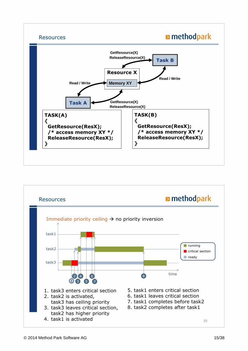
Immediate priority ceiling � no priority inversion
30
time
task1
task2
task3
running
critical section
ready
1. task3 enters critical section2. task2 is activated,
task3 has ceiling priority3. task3 leaves critical section,
task2 has higher priority4. task1 is activated
5. task1 enters critical section6. task1 leaves critical section7. task1 completes before task28. task2 completes after task1
1
2
3
4
5 7
6 8
© 2014 Method Park Software AG 15/38
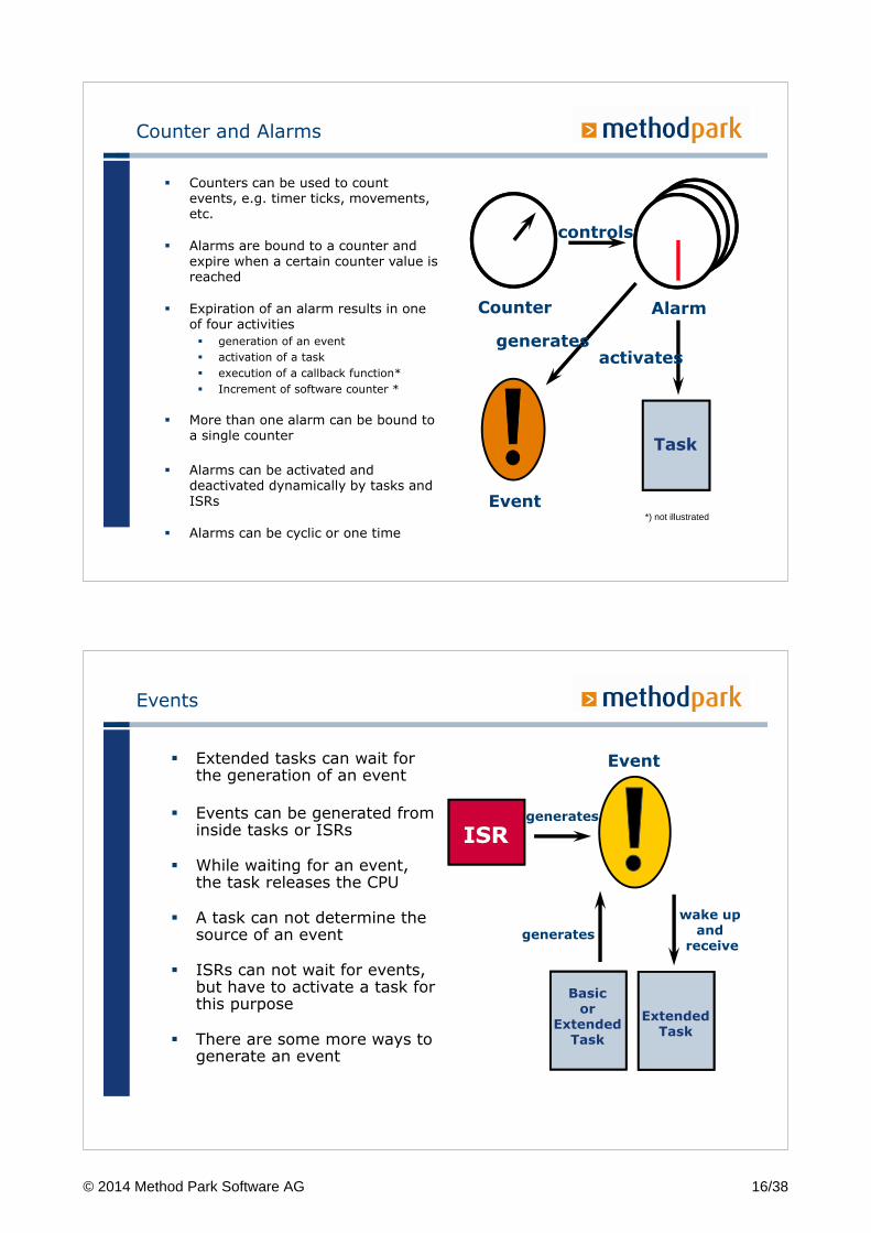
Counter and Alarms
Counter Alarm
controls
Task
Event
generatesactivates
*) not illustrated
� Counters can be used to count events, e.g. timer ticks, movements, etc.
� Alarms are bound to a counter and expire when a certain counter value is reached
� Expiration of an alarm results in one of four activities
� generation of an event
� activation of a task
� execution of a callback function*
� Increment of software counter *
� More than one alarm can be bound to a single counter
� Alarms can be activated and deactivated dynamically by tasks and ISRs
� Alarms can be cyclic or one time
Events
wake up and
receive
Basicor
ExtendedTask
Event
ISRgenerates
generates
ExtendedTask
� Extended tasks can wait for the generation of an event
� Events can be generated from inside tasks or ISRs
� While waiting for an event, the task releases the CPU
� A task can not determine the source of an event
� ISRs can not wait for events, but have to activate a task for this purpose
� There are some more ways to generate an event
© 2014 Method Park Software AG 16/38
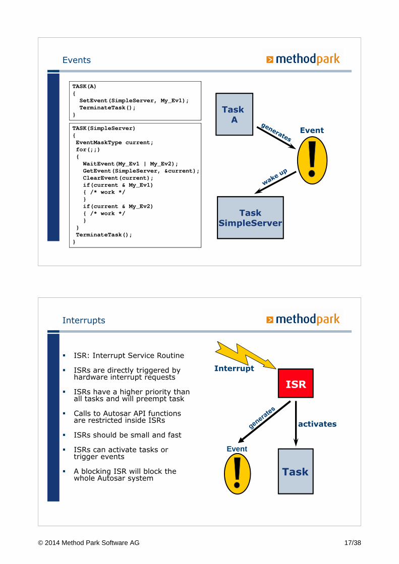
Events
TaskSimpleServer
Event
Task A
TASK(A) {SetEvent(SimpleServer, My_Ev1);TerminateTask();
}
TASK(SimpleServer) {EventMaskType current;for(;;) { WaitEvent(My_Ev1 | My_Ev2);GetEvent(SimpleServer, ¤t);ClearEvent(current);if(current & My_Ev1) { /* work */}if(current & My_Ev2) { /* work */}
}TerminateTask();}
Interrupts
� ISR: Interrupt Service Routine
� ISRs are directly triggered by hardware interrupt requests
� ISRs have a higher priority than all tasks and will preempt task
� Calls to Autosar API functions are restricted inside ISRs
� ISRs should be small and fast
� ISRs can activate tasks or trigger events
� A blocking ISR will block the whole Autosar system
Task
Interrupt
ISR
activates
Event
© 2014 Method Park Software AG 17/38
Interrupts
Interrupts can be used for jobs with high urgency
� An interrupt signals an event that must be handled immediately
� Currently executing code is preempted with the interrupt handling code
The source of an interrupts can be in hardware or software:
� Hardware interrupts: e.g. hall sensor, data received…
� Software interrupts: e.g. division by zero, system call, …
35
Interrupts
What is allowed within an interrupt handler?
� Which operating system calls?
� Floating point operations?
� Check operating system documentation
Example: OSEK has two categories of interrupt handlers
� Category 1: no operating system services may be used
� Category 2: system services can be used
36
© 2014 Method Park Software AG 18/38
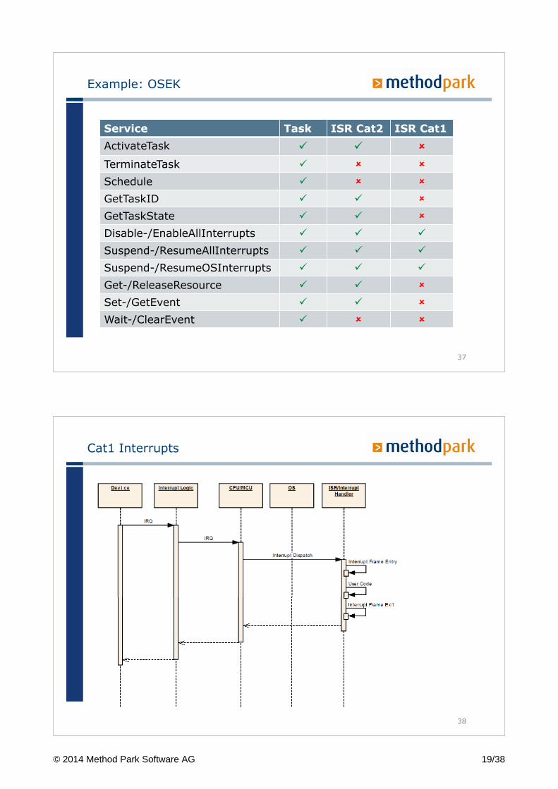
Example: OSEK
Service Task ISR Cat2 ISR Cat1
ActivateTask � � �
TerminateTask � � �
Schedule � � �
GetTaskID � � �
GetTaskState � � �
Disable-/EnableAllInterrupts � � �
Suspend-/ResumeAllInterrupts � � �
Suspend-/ResumeOSInterrupts � � �
Get-/ReleaseResource � � �
Set-/GetEvent � � �
Wait-/ClearEvent � � �
37
Cat1 Interrupts
38
© 2014 Method Park Software AG 19/38
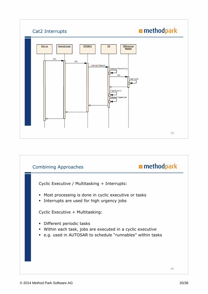
Cat2 Interrupts
39
Combining Approaches
Cyclic Executive / Multitasking + Interrupts:
� Most processing is done in cyclic executive or tasks
� Interrupts are used for high urgency jobs
Cyclic Executive + Multitasking:
� Different periodic tasks
� Within each task, jobs are executed in a cyclic executive
� e.g. used in AUTOSAR to schedule “runnables” within tasks
40
© 2014 Method Park Software AG 20/38
Concurrency – Interrupts
Problem: Concurrent access to data shared by tasks and interrupt handlers
� Synchronization is necessary
Approaches:
� Disabling Interrupts
� Using operating system mechanisms
� Queues, semaphores, mutexs
� Needs to be non-blocking in ISR!
41
Overview
42
� Automotive Domain
� OSEK/VDX
� AUTOSAR
� Summary
© 2014 Method Park Software AG 21/38
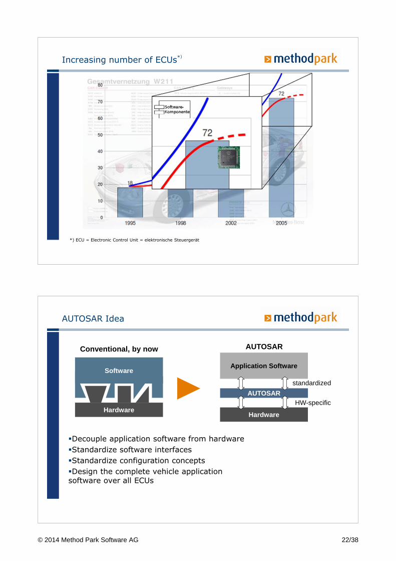
Increasing number of ECUs*)
*) ECU = Electronic Control Unit = elektronische Steuergerät
AUTOSAR Idea
�Decouple application software from hardware
�Standardize software interfaces
�Standardize configuration concepts
�Design the complete vehicle applicationsoftware over all ECUs
Hardware
Software
Conventional, by now
Application Software
Hardware
AUTOSAR
standardized
HW-specific
AUTOSAR
© 2014 Method Park Software AG 22/38
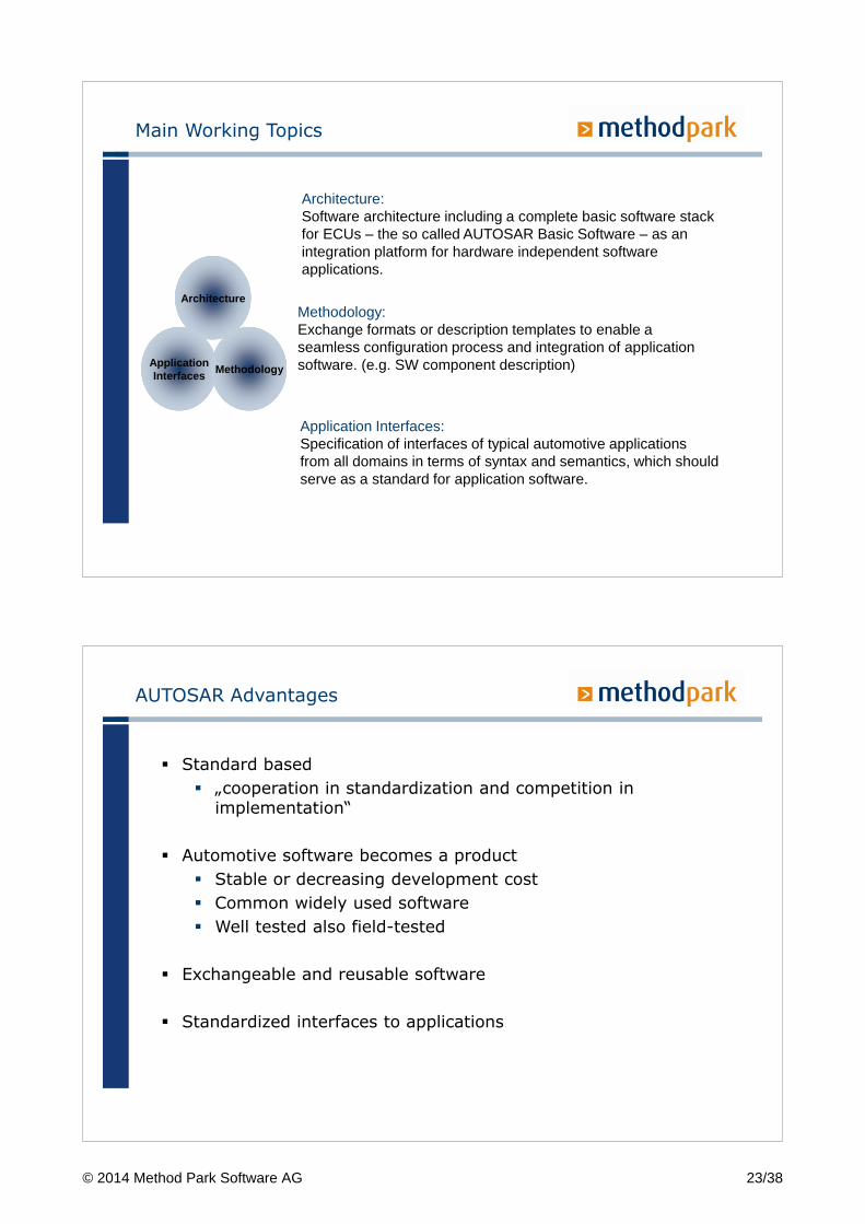
Main Working Topics
ApplicationInterfaces
Methodology
Architecture
Architecture:Software architecture including a complete basic software stack for ECUs – the so called AUTOSAR Basic Software – as an integration platform for hardware independent software applications.
Methodology:Exchange formats or description templates to enable a seamless configuration process and integration of application software. (e.g. SW component description)
Application Interfaces:Specification of interfaces of typical automotive applications from all domains in terms of syntax and semantics, which should serve as a standard for application software.
AUTOSAR Advantages
� Standard based
� „cooperation in standardization and competition in implementation“
� Automotive software becomes a product
� Stable or decreasing development cost
� Common widely used software
� Well tested also field-tested
� Exchangeable and reusable software
� Standardized interfaces to applications
© 2014 Method Park Software AG 23/38
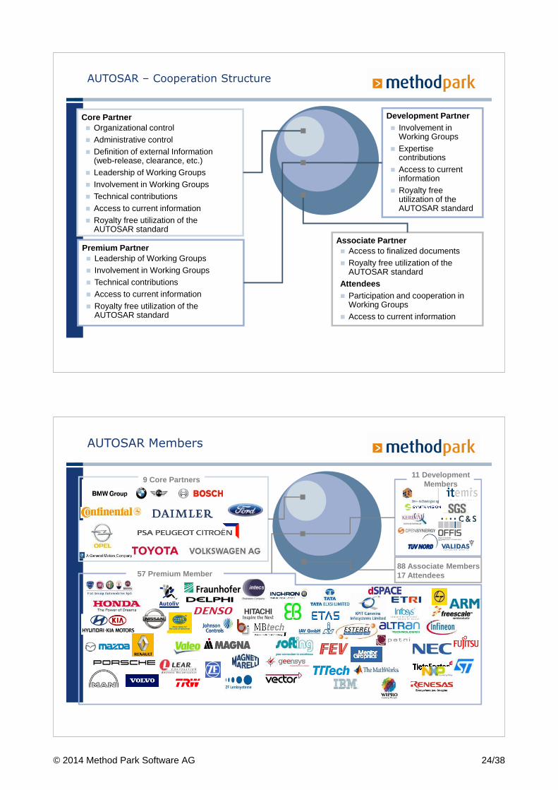
Premium Partner� Leadership of Working Groups� Involvement in Working Groups� Technical contributions � Access to current information� Royalty free utilization of the
AUTOSAR standard
Development Partner� Involvement in
Working Groups� Expertise
contributions � Access to current
information� Royalty free
utilization of the AUTOSAR standard
Core Partner� Organizational control� Administrative control� Definition of external Information
(web-release, clearance, etc.)� Leadership of Working Groups� Involvement in Working Groups� Technical contributions� Access to current information� Royalty free utilization of the
AUTOSAR standard Associate Partner� Access to finalized documents� Royalty free utilization of the
AUTOSAR standard Attendees� Participation and cooperation in
Working Groups� Access to current information
AUTOSAR – Cooperation Structure
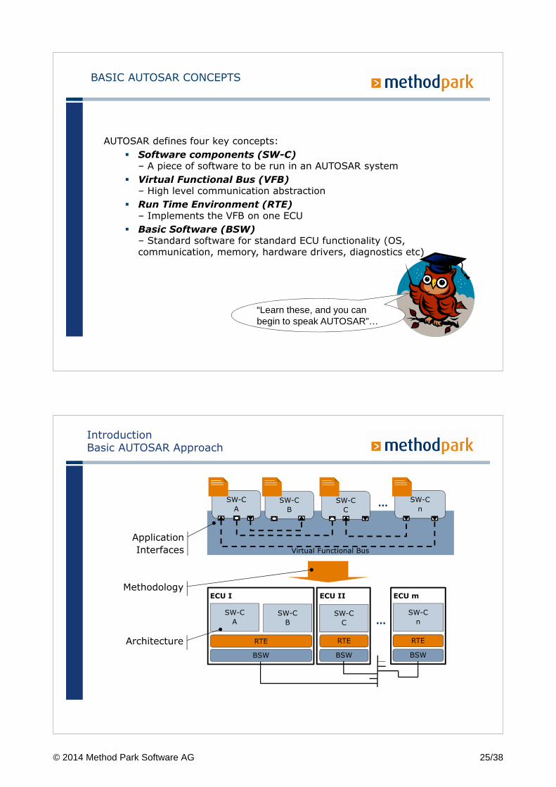
AUTOSAR Members
88 Associate Members17 Attendees57 Premium Member
9 Core Partners 11 Development
Members
© 2014 Method Park Software AG 24/38
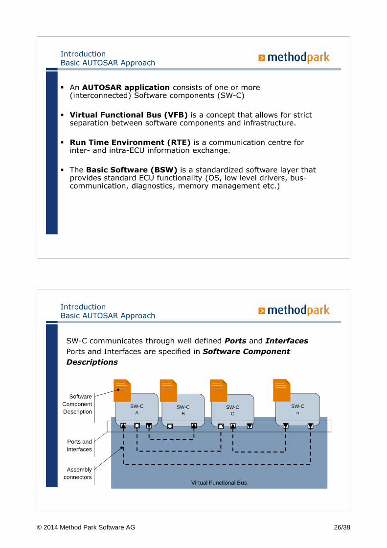
BASIC AUTOSAR CONCEPTS
AUTOSAR defines four key concepts:
� Software components (SW-C)– A piece of software to be run in an AUTOSAR system
� Virtual Functional Bus (VFB)– High level communication abstraction
� Run Time Environment (RTE)– Implements the VFB on one ECU
� Basic Software (BSW)– Standard software for standard ECU functionality (OS, communication, memory, hardware drivers, diagnostics etc)
“Learn these, and you can begin to speak AUTOSAR”…
SW-C
A
SW-C
B
SW-C
nSW-C
C
RTE
BSW
RTE
BSW
RTE
BSW
ECU I ECU II ECU m
SW-C
A
SW-C
B
SW-C
nSW-C
C
Virtual Functional Bus
Application
Interfaces
Methodology
Architecture
…
…
IntroductionBasic AUTOSAR Approach
© 2014 Method Park Software AG 25/38
IntroductionBasic AUTOSAR Approach
� An AUTOSAR application consists of one or more (interconnected) Software components (SW-C)
� Virtual Functional Bus (VFB) is a concept that allows for strict separation between software components and infrastructure.
� Run Time Environment (RTE) is a communication centre for inter- and intra-ECU information exchange.
� The Basic Software (BSW) is a standardized software layer that provides standard ECU functionality (OS, low level drivers, bus-communication, diagnostics, memory management etc.)
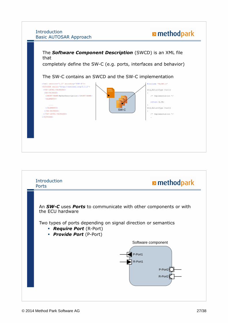
IntroductionBasic AUTOSAR Approach
SW-C communicates through well defined Ports and Interfaces
Ports and Interfaces are specified in Software Component
Descriptions
SW-CA
SW-CB
SW-Cn
SW-CC
Virtual Functional Bus
Software ComponentDescription
Ports and Interfaces
Assembly connectors
© 2014 Method Park Software AG 26/38
The Software Component Description (SWCD) is an XML file that
completely define the SW-C (e.g. ports, interfaces and behavior)
The SW-C contains an SWCD and the SW-C implementation
IntroductionBasic AUTOSAR Approach
<?xml version ="1.0" encoding =" UTF-8 "?>
<AUTOSAR xmlns =" http://autosar.org/3.1.2 " >
<TOP-LEVEL-PACKAGES>
<AR-PACKAGE>
<SHORT-NAME>MySwcDescription </ SHORT-NAME>
<ELEMENTS>
....
</ ELEMENTS>
</ AR-PACKAGE>
</ TOP-LEVEL-PACKAGES>
</ AUTOSAR>
SW-C
#include ”MySWC.h”
Std_ReturnType fun1()
{
/* Implementation */
return E_OK;
}
Std_ReturnType fun2()
{
/* Implementation */
…
IntroductionPorts
An SW-C uses Ports to communicate with other components or with the ECU hardware
Two types of ports depending on signal direction or semantics
� Require Port (R-Port)
� Provide Port (P-Port)
P-Port1
R-Port1
P-Port2
R-Port2
Software component
© 2014 Method Park Software AG 27/38
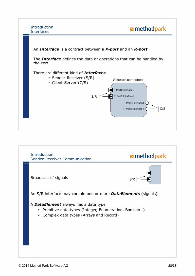
IntroductionInterfaces
An Interface is a contract between a P-port and an R-port
The Interface defines the data or operations that can be handled by the Port
There are different kind of Interfaces
� Sender-Receiver (S/R)
� Client-Server (C/S)
P-Port1:Interface1
R-Port1:Interface2
P-Port2:Interface3
R-Port2:Interface4
Software component
S/R
C/S
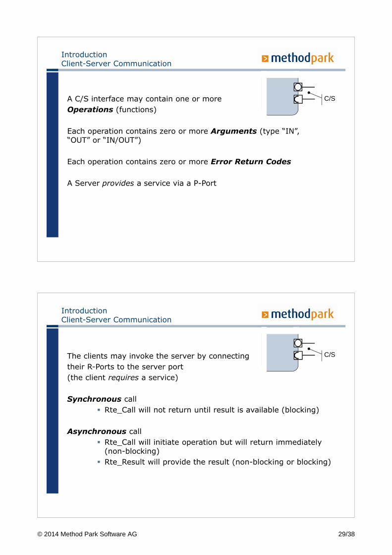
IntroductionSender-Receiver Communication
Broadcast of signals
An S/R interface may contain one or more DataElements (signals)
A DataElement always has a data type
� Primitive data types (Integer, Enumeration, Boolean…)
� Complex data types (Arrays and Record)
S/R
© 2014 Method Park Software AG 28/38
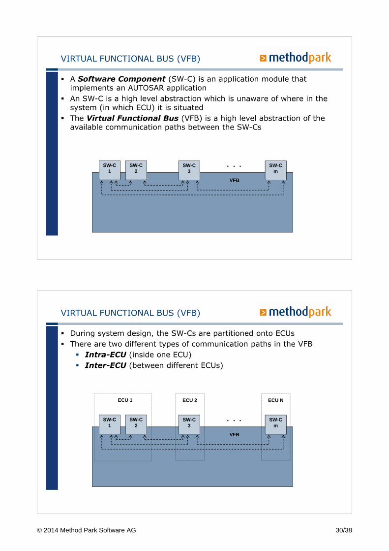
A C/S interface may contain one or more
Operations (functions)
Each operation contains zero or more Arguments (type “IN”, “OUT” or “IN/OUT”)
Each operation contains zero or more Error Return Codes
A Server provides a service via a P-Port
IntroductionClient-Server Communication
C/S
The clients may invoke the server by connecting
their R-Ports to the server port
(the client requires a service)
Synchronous call
� Rte_Call will not return until result is available (blocking)
Asynchronous call
� Rte_Call will initiate operation but will return immediately (non-blocking)
� Rte_Result will provide the result (non-blocking or blocking)
IntroductionClient-Server Communication
C/S
© 2014 Method Park Software AG 29/38
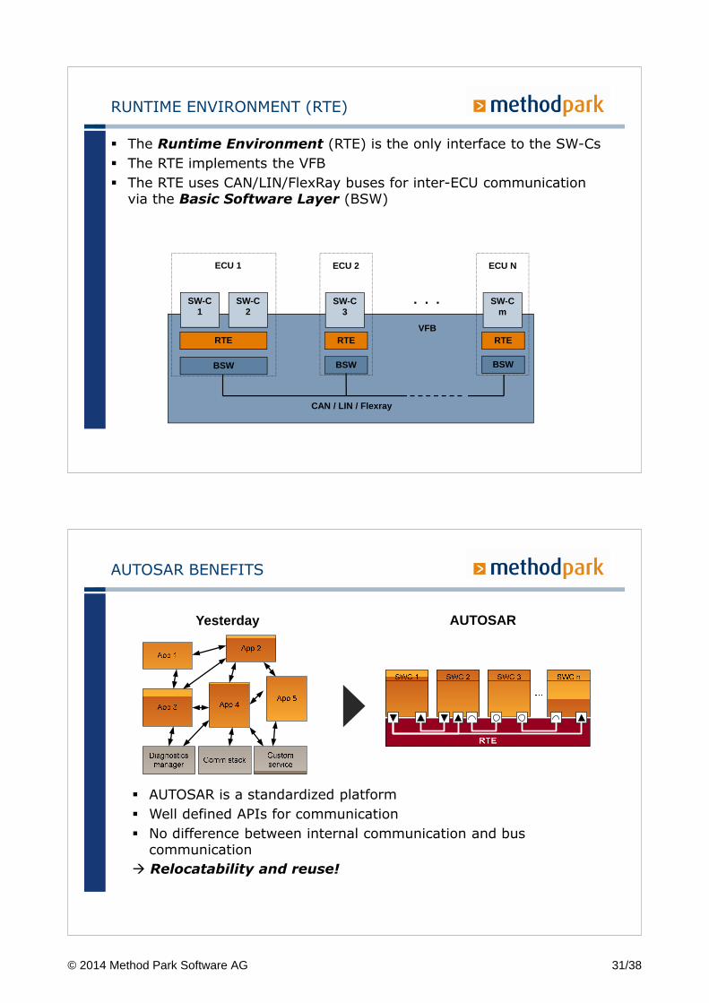
VIRTUAL FUNCTIONAL BUS (VFB)
� A Software Component (SW-C) is an application module that implements an AUTOSAR application
� An SW-C is a high level abstraction which is unaware of where in the system (in which ECU) it is situated
� The Virtual Functional Bus (VFB) is a high level abstraction of the available communication paths between the SW-Cs
SW-C1
SW-C2
SW-C3
SW-Cm
. . .
VFB
VIRTUAL FUNCTIONAL BUS (VFB)
� During system design, the SW-Cs are partitioned onto ECUs
� There are two different types of communication paths in the VFB
� Intra-ECU (inside one ECU)
� Inter-ECU (between different ECUs)
SW-C1
SW-C2
SW-C3
SW-Cm
. . .
VFB
ECU 1 ECU 2 ECU N
© 2014 Method Park Software AG 30/38
RUNTIME ENVIRONMENT (RTE)
� The Runtime Environment (RTE) is the only interface to the SW-Cs
� The RTE implements the VFB
� The RTE uses CAN/LIN/FlexRay buses for inter-ECU communication via the Basic Software Layer (BSW)
SW-C3
SW-Cm
. . .
VFB
ECU 2 ECU N
SW-C1
SW-C2
ECU 1
RTE
BSW
RTE
BSW
RTE
BSW
CAN / LIN / Flexray
AUTOSAR BENEFITS
� AUTOSAR is a standardized platform
� Well defined APIs for communication
� No difference between internal communication and bus communication
� Relocatability and reuse!
Yesterday AUTOSAR
© 2014 Method Park Software AG 31/38
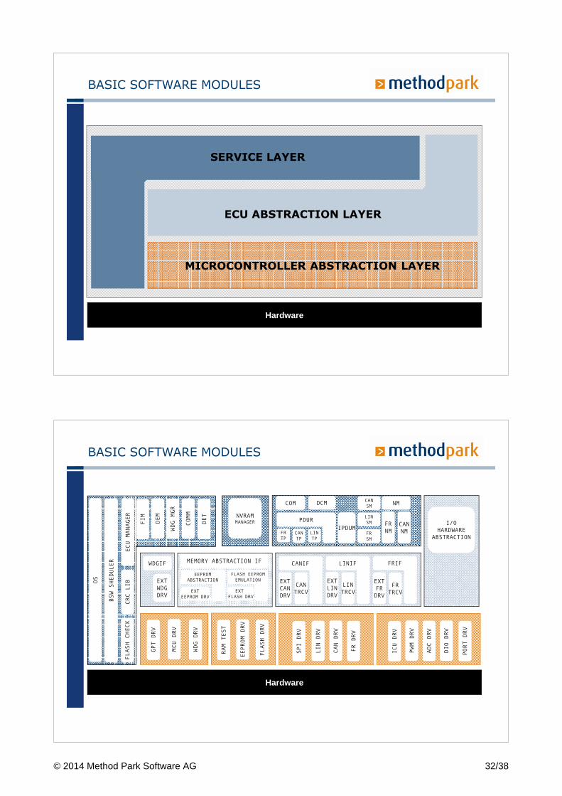
BASIC SOFTWARE MODULES
Hardware
SERVICE LAYER
ECU ABSTRACTION LAYER
MICROCONTROLLER ABSTRACTION LAYER
BASIC SOFTWARE MODULES
Hardware
EXT
LIN
DRV
LIN
TRCV
EXT
FR
DRV
FR
TRCV
EXT
CAN
DRV
CAN
TRCV
NVRAM
MANAGER
WDGIF
EXT
WDG
DRV
I/O
HARDWARE
ABSTRACTION
OS
BSW SHEDULER
ECU MANAGER
CRC LIB
FLASH CHECK
FIM
DEM
WDG MGR
COMM
DET
SPI DRV
LIN DRV
CAN DRV
FR DRV
ICU DRV
PWM DRV
ADC DRV
DIO DRV
PORT DRV
RAM TEST
EEPROM DRV
FLASH DRV
GPT DRV
MCU DRV
WDG DRV
CANIF LINIF FRIF
EEPROM
ABSTRACTION
EXT
EEPROM DRV
MEMORY ABSTRACTION IF
FLASH EEPROM
EMULATION
EXT
FLASH DRV
CAN
SM
LIN
SM
FR
SM
IPDUMFR
TP
CAN
TP
LIN
TP
COM DCM NM
FR
NM
CAN
NM
PDUR
© 2014 Method Park Software AG 32/38
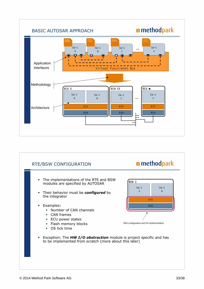
BASIC AUTOSAR APPROACH
SW-C
A
SW-C
B
SW-C
n
SW-C
C
RTE
BSW
RTE
BSW
RTE
BSW
ECU IECU IECU IECU I ECU IIECU IIECU IIECU II ECU mECU mECU mECU m
SW-C
A
SW-C
B
SW-C
n
SW-C
C
Virtual Functional Bus
ApplicationInterfaces
Methodology
Architecture
…
…
� The implementations of the RTE and BSWmodules are specified by AUTOSAR
� Their behavior must be configured bythe integrator
� Examples:
� Number of CAN channels
� CAN frames
� ECU power states
� Flash memory blocks
� OS tick time
� Exception: The HW I/O abstraction module is project specific and has to be implemented from scratch (more about this later)
RTE/BSW CONFIGURATION
BSW
SW-C
A
SW-C
B
RTE
ECU IECU IECU IECU I
95% configuration and 5% implementation
© 2014 Method Park Software AG 33/38
SW-C CONFIGURATION
� SW-Cs are also configured to some extent
� Examples:
� Data Types
� Communication signals
� Scheduling
� Inter task communication
� Based on this configuration, the RTE will provide the necessary APIs
� The source code in the SW-Cs can either be implemented manually (coding C or C++) or modeled using e.g. Simulink or Targetlink
SW-C
A
SW-C
B
RTE
ECU IECU IECU IECU I
BSW
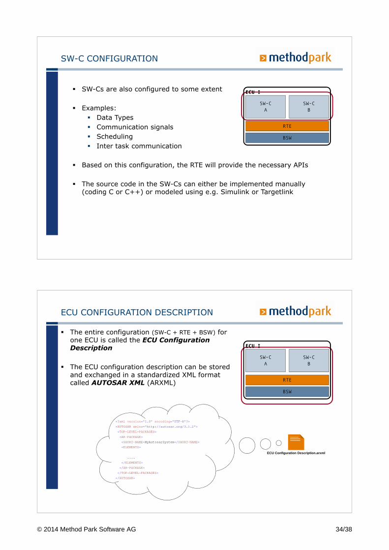
ECU CONFIGURATION DESCRIPTION
� The entire configuration (SW-C + RTE + BSW) for one ECU is called the ECU Configuration Description
� The ECU configuration description can be stored and exchanged in a standardized XML format called AUTOSAR XML (ARXML)
<?xml version =" 1.0 " encoding =" UTF-8 " ?>
<AUTOSARxmlns =" http://autosar.org/3.1.2 " >
<TOP-LEVEL-PACKAGES>
<AR-PACKAGE>
<SHORT-NAME>MyAutosarSystem </ SHORT-NAME>
<ELEMENTS>
....
</ ELEMENTS>
</ AR-PACKAGE>
</ TOP-LEVEL-PACKAGES>
</ AUTOSAR>
ECU Configuration Description.arxml
SW-C
A
SW-C
B
RTE
ECU IECU IECU IECU I
BSW
© 2014 Method Park Software AG 34/38
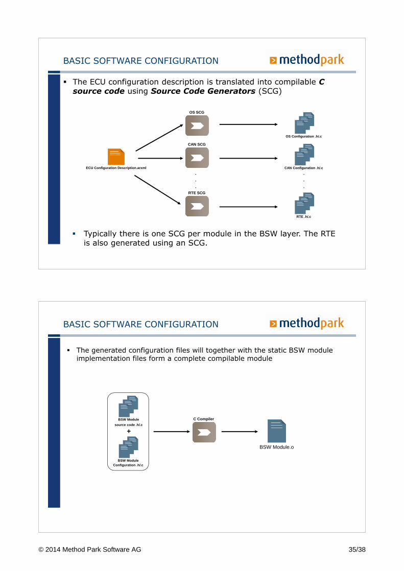
BASIC SOFTWARE CONFIGURATION
� The ECU configuration description is translated into compilable C source code using Source Code Generators (SCG)
ECU Configuration Description.arxml
OS Configuration .h/.c
OS SCG
CAN SCG
RTE SCG
.
.
.
CAN Configuration .h/.c
RTE .h/.c
.
.
.
� Typically there is one SCG per module in the BSW layer. The RTE is also generated using an SCG.
BASIC SOFTWARE CONFIGURATION
� The generated configuration files will together with the static BSW module implementation files form a complete compilable module
BSW Module Configuration .h/.c
BSW Module.o
+
C CompilerBSW Module
source code .h/.c
© 2014 Method Park Software AG 35/38
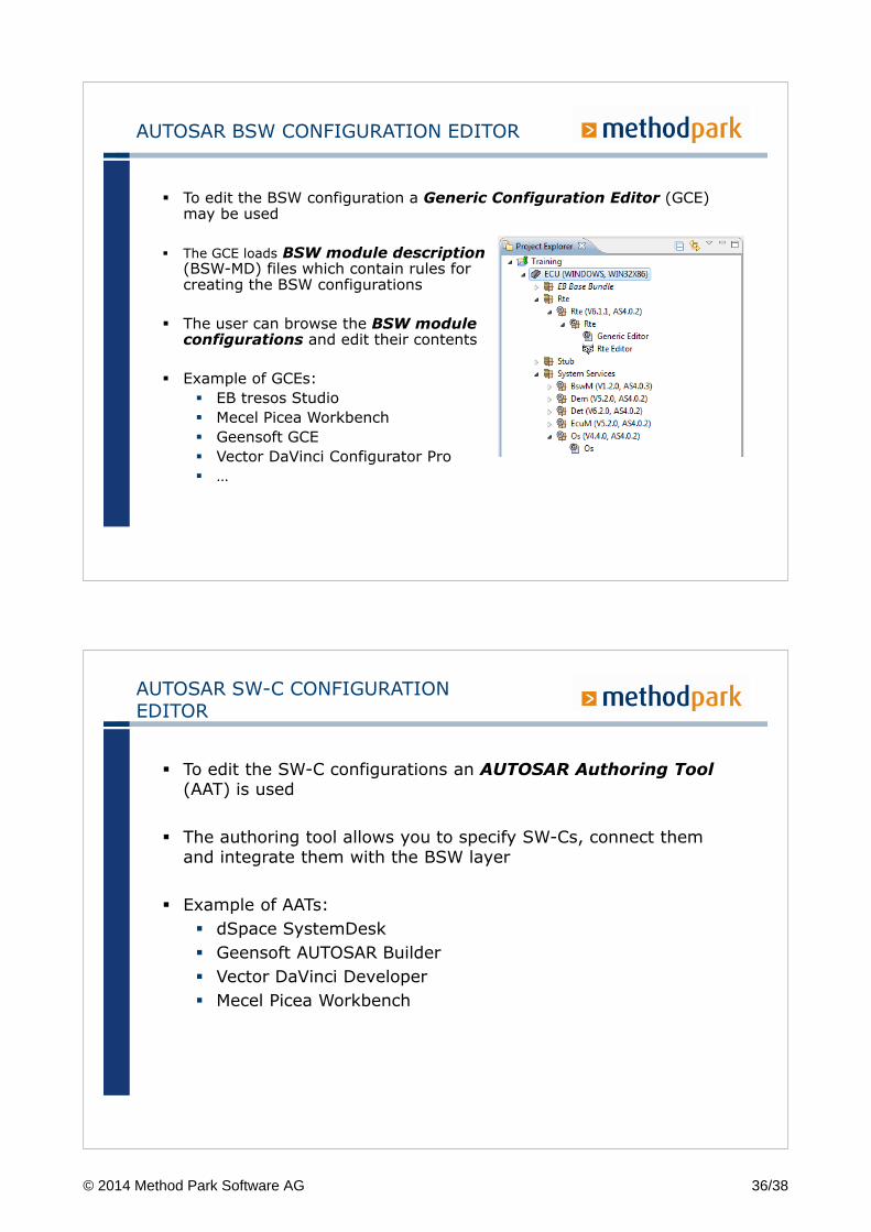
AUTOSAR BSW CONFIGURATION EDITOR
� To edit the BSW configuration a Generic Configuration Editor (GCE) may be used
� The GCE loads BSW module description(BSW-MD) files which contain rules forcreating the BSW configurations
� The user can browse the BSW moduleconfigurations and edit their contents
� Example of GCEs:
� EB tresos Studio
� Mecel Picea Workbench
� Geensoft GCE
� Vector DaVinci Configurator Pro
� …
AUTOSAR SW-C CONFIGURATION EDITOR
� To edit the SW-C configurations an AUTOSAR Authoring Tool(AAT) is used
� The authoring tool allows you to specify SW-Cs, connect them and integrate them with the BSW layer
� Example of AATs:
� dSpace SystemDesk
� Geensoft AUTOSAR Builder
� Vector DaVinci Developer
� Mecel Picea Workbench
© 2014 Method Park Software AG 36/38
AUTOSAR OS
OSEK/VDX with new features
� Memory protection
� Timing protection
� Service protection
� Schedule tables
� Inter-OS-Application Communicator (IOC)
73
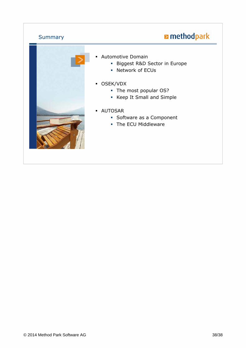
Schedule Table
� A Schedule Table is a predefined sequence of actions (expiry points)
� Os iterates over the Schedule Table and processes each expiry point in turn
� Actions on a expiry point� ActivateTask()� SetEvent()
� Schedule Table is attached to a counter which provides the underlying interval measurement
� ScheduleTable can be startedrelatively or absolutely tothe current counter value
� Schedule Table modes� One shot� Periodic A
ctiv
ateT
ask
Set
Eve
nt
Act
ivat
eTas
k
Act
ivat
eTas
kS
etE
vent
0
Duration
5 10
© 2014 Method Park Software AG 37/38
Summary
� Automotive Domain
� Biggest R&D Sector in Europe
� Network of ECUs
� OSEK/VDX
� The most popular OS?
� Keep It Small and Simple
� AUTOSAR
� Software as a Component
� The ECU Middleware
© 2014 Method Park Software AG 38/38