Embed Size (px)
Citation preview
ZXSDR BTS Structure and Principle
Objectives
Introduction to ZXSDR Main Features of ZXSDR Main Differences Between ZXSDR and
Traditional 2G BTS ZXSDR BTS Family Introduction ZXSDR BTS Hardware Function Configuration of ZXSDR Alarm Handling
Introduction to ZXSDR
Challenges in the Development of Communication Technology
SDR Concept

Challenge in the Development of Communication Technology With the increasing communication demands, new
technologies come out in succession. The common concern for communication operators and equipment suppliers is how to upgrade equipment more flexibly and protect the investment of operators to greatest extent in the continuous technology updates.
The SDR concept is proposed for this problem.
SDR Concept
The software defined radio (SDR) is defined as radio in which some or all of the physical layer functions are software defined.
SDR Concept
The traditional communication equipment, namely the hardware radio (HR), functions through the hardware. Therefore, functions are often improved by upgrading the equipment. SDR uses the hardware as a general processing platform and functions through the software
Why to Select ZXSDR Series BTS?
ZTE SDR serial BTS are a brand-new series of radio products designed and produced by ZTE. They use the advanced SDR technology and their hardware structure is based on the uniform platform of ZTE, innovatively
supporting multiple radio access methods, including GSM, UMTS, CDMA2000, and WiMAX. In addition, SDR can be smoothly evolved into the Enhanced EDGE/LTE.
Main Features of ZXSDR
High-integrity Flexible Architecture Multiple New Functions Lower Cost
Main Features of ZXSDR
GSM networking mainly uses three types of SDR BTS:
the first is indoor macro BTS 8800 the second is outdoor macro BTS8900
Main Features of ZXSDR
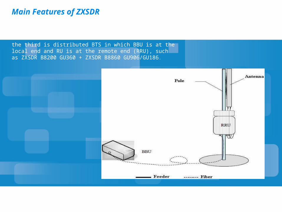
the third is distributed BTS in which BBU is at the local end and RU is at the remote end (RRU), such as ZXSDR B8200 GU360 + ZXSDR B8860 GU906/GU186.
High-integrity
Based on the All-IP transmission structure. Support RU of multiple bands. BBU supports 60TRX, and RU supports 6TRX/2TRX.
RU60 board supports 6TRX, and RU02 board supports 2TRX.
One fiber supports 24 TRXs. 2G supports a maximum capacity of S666666 or
S12/12/12; 3G supports a maximum of 12CS; the dual mode supports a maximum of S333 + S666 (GSM + UMTS).
Support the smooth evolution to LTE and HSPA+
Flexible Architecture
Support the macro BTS and RRU BBU and RU within a cabinet is called a macro BTS.
RRU is called a distributed BTS Support FE/GE and E1/T1 (IPOE)
Do not support the channelized E1/T1 currently Support the indoor/outdoor type Small size, light weight, energy-saving and
environment protection Support the technology evolution
Multiple New Functions
Baseband frequency hopping Transmit/receive diversity DDT/DPCT Multi-carrier combination
Lower Cost
Reduced unit cost Reduced typical networking cost Saved ABIS bandwidth Reduced operating cost Reduced maintenance cost
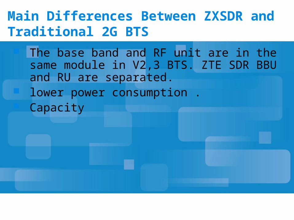
Main Differences Between ZXSDR and Traditional 2G BTS The base band and RF unit are in the same
module in V2,3 BTS. ZTE SDR BBU and RU are separated.
lower power consumption . Capacity
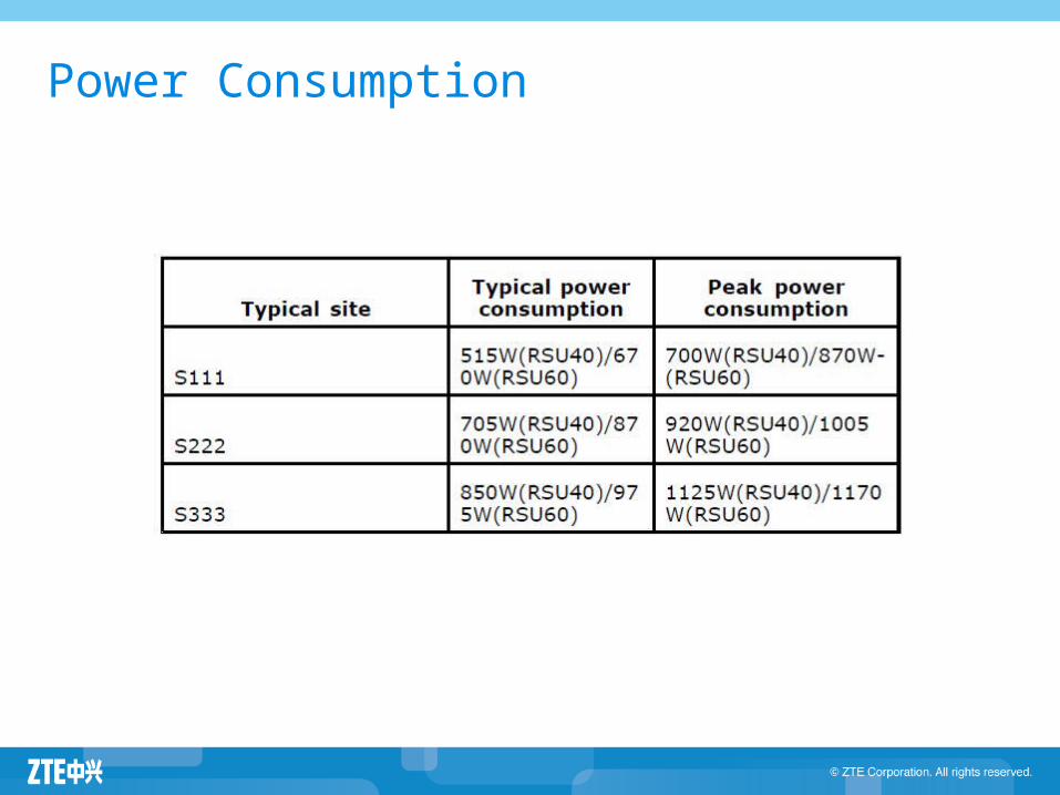
Power Consumption
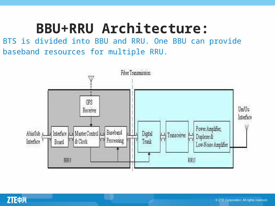
BB BBU+RRU Architecture:ArchBTS is divided into BBU and RRU. One BBU can provide baseband resources for multiple RRU.itec
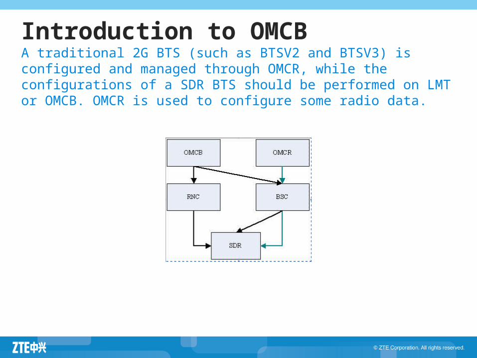
Introduction to OMCBA traditional 2G BTS (such as BTSV2 and BTSV3) is configured and managed through OMCR, while the configurations of a SDR BTS should be performed on LMT or OMCB. OMCR is used to configure some radio data.
to OMCB
IP Abis Interface
The other major difference for a SDR BTS from a traditional 2G BTS is that the Abis/Iub uses IP protocol. Its physical bearer can be FE/GE or E1/T1 (IP over E1/T1), but not the E1/T1 of TDMBTS can fully use the existing transmission equipment to save the user investment; if FE/GE is used, BTS will obtain more bandwidth, which is oriented to the communication system evolution to all IP.
ZXSDR BTS Family Introduction
ZXSDR BS8700 ZXSDR BS8800 ZXSDR BS8900 ZXSDR BS8906 ZXSDR BTS Work Principle ZXSDR BTS Operation and Maintenance
BS8700
BS8900
BS8800
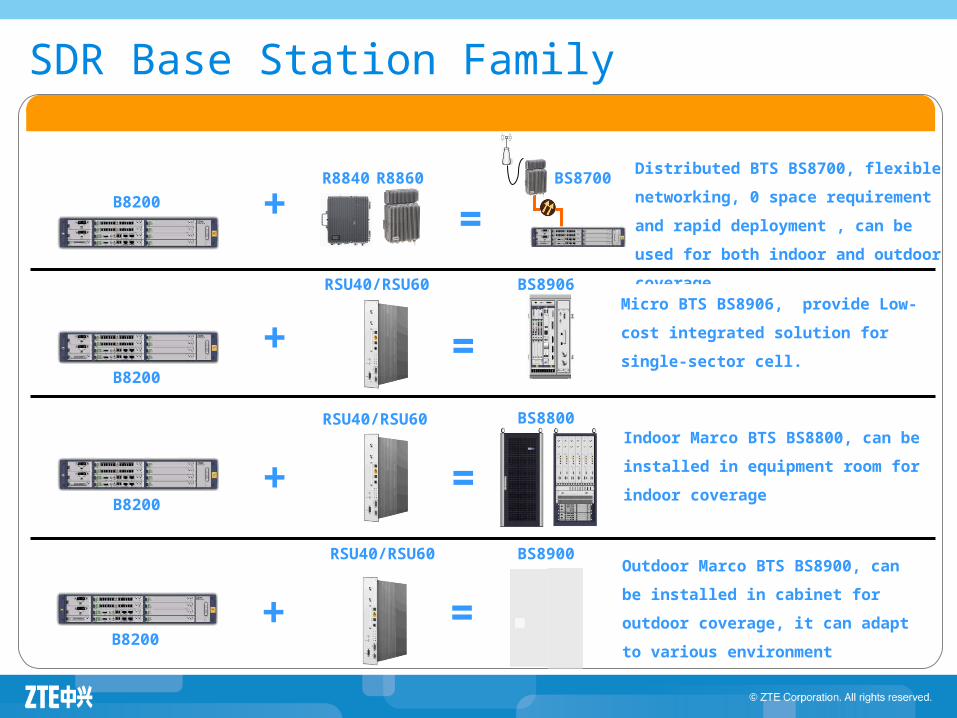
Distributed BTS BS8700, flexible
networking, 0 space requirement and
rapid deployment , can be used for both
indoor and outdoor coverage
B8200R8860
RSU40/RSU60
+
+ =
Indoor Marco BTS BS8800, can be
installed in equipment room for indoor
coverage
RSU40/RSU60
+ =
Outdoor Marco BTS BS8900, can be
installed in cabinet for outdoor
coverage, it can adapt to various
environment
=
B8200
B8200
Micro BTS BS8906, provide Low-cost
integrated solution for single-sector
cell.
BS8906
+ =B8200
RSU40/RSU60
R8840
SDR Base Station Family
Agenda
ZXSDR BTS Family Introduction ZXSDR BS8700 ZXSDR BS8800 ZXSDR BS8900 ZXSDR BS8906 ZXSDR BTS Work Principle ZXSDR BTS Operation and Maintenance
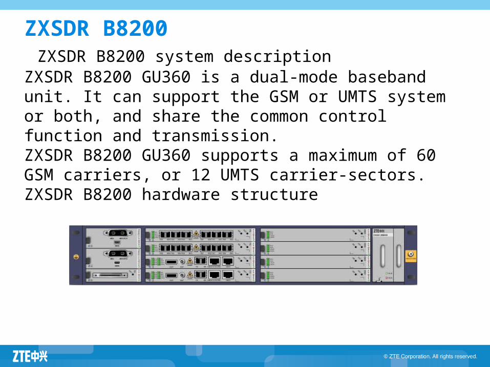
ZXSDR B8200 ZXSDR B8200 system descriptionZXSDR B8200 GU360 is a dual-mode baseband unit. It can support the GSM or UMTS system or both, and share the common control function and transmission.ZXSDR B8200 GU360 supports a maximum of 60 GSM carriers, or 12 UMTS carrier-sectors.ZXSDR B8200 hardware structure
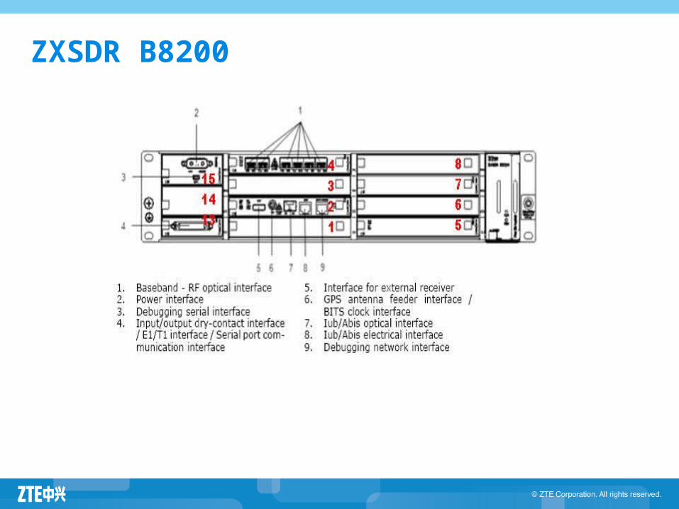
ZXSDR B8200
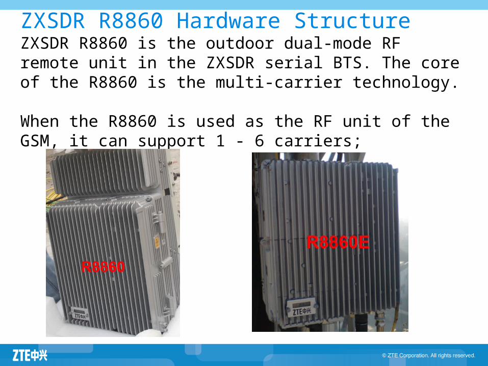
ZXSDR R8860 Hardware StructureZXSDR R8860 is the outdoor dual-mode RF remote unit in the ZXSDR serial BTS. The core of the R8860 is the multi-carrier technology. When the R8860 is used as the RF unit of the GSM, it can support 1 - 6 carriers;

ZXSDR R8860 Hardware Structure
The R8860 can be categorized into ZXSDR R8860 GU906 and ZXSDR R8860 GU186. The GU indicates that the GSM and UMTS dual modes
are supported. The 906 indicates that the GSM900 and UMTS900 are
supported, and the transmitting power is 80 W. The 186 indicates that the GSM1800 and UMTS1800
are supported, and the transmitting power is 80 W.
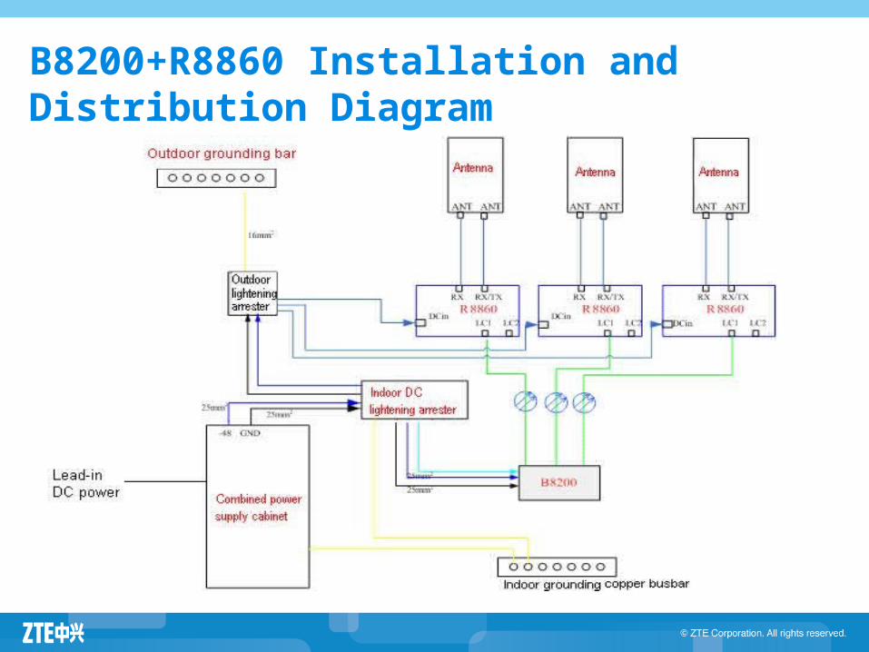
B8200+R8860 Installation and Distribution Diagram
ZXSDR BS8700
ZXSDR BS8700 consists of BBU (B8200) and RRU (R8860). 8200 is an indoor GSM/UMTS dual-mode BBU product. R8860 is an
outdoor GSM/UMTS dual-mode remote radio unit. B8200 and R8600 work in cooperation to implement BTS/Node B functions. BS8700 supports GSM (850 MHz/900 MHz/1800 MHz/1900 MHz) and UMTS (850 MHz/900 MHz/1800 MHz/1900 MHz). It can also independently serve as a GSM or UMTS macro base station.
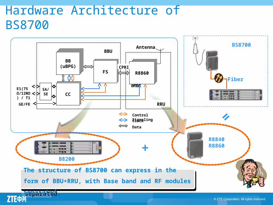
Hardware Architecture of BS8700
B8200+
=R8840R8860
BS8700
Fiber
BBU
Radio UnitRadio Unit
SA/SE CC
BB(uBPG)
FS R8860
E1(75 Ω/120Ω) / T1
GE/FE
Clock Data
Control Signaling
Antenna
RRU
CPRI
The structure of BS8700 can express in the form of
BBU+RRU, with Base band and RF modules separated.
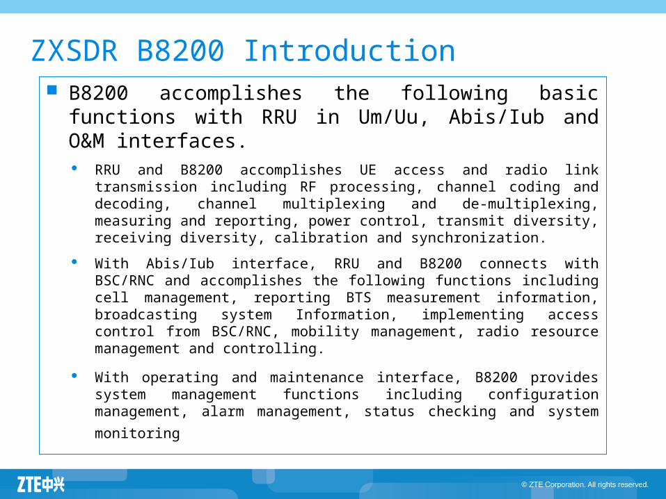
B8200 accomplishes the following basic functions with RRU in Um/Uu, Abis/Iub and O&M interfaces.
RRU and B8200 accomplishes UE access and radio link transmission including RF processing, channel coding and decoding, channel multiplexing and de-multiplexing, measuring and reporting, power control, transmit diversity, receiving diversity, calibration and synchronization.
With Abis/Iub interface, RRU and B8200 connects with BSC/RNC and accomplishes the following functions including cell management, reporting BTS measurement information, broadcasting system Information, implementing access control from BSC/RNC, mobility management, radio resource management and controlling.
With operating and maintenance interface, B8200 provides system management functions including configuration management, alarm management, status checking and system monitoring
ZXSDR B8200 Introduction
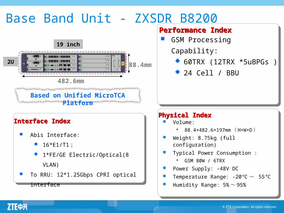
Based on Unified MicroTCA Platform
Base Band Unit - ZXSDR B8200
Volume: 88.4×482.6×197mm ( H×W×D )
Weight: 8.75kg (full configuration) Typical Power Consumption :
GSM 80W / 6TRX Power Supply: -48V DC Temperature Range: -20℃~ 55℃ Humidity Range: 5% ~ 95%
2U
482.6mm
88.4mm
GSM Processing Capability:
60TRX (12TRX *5uBPGs ) 24 Cell / BBU
Abis Interface: 16*E1/T1 ; 1*FE/GE Electric/Optical(8 VLAN)
To RRU: 12*1.25Gbps CPRI optical interface
Performance IndexPerformance Index
Physical IndexPhysical IndexInterface IndexInterface Index
19 inch

Star Topology
Chain Topology
BSC
E1/T1
STM-1
B8200
B8200
RRURRU
ZTE provides flexible networking for distributed site such as star, ZTE provides flexible networking for distributed site such as star, chain, loop and mix topology to meet demands for customers.chain, loop and mix topology to meet demands for customers.
Networking Topology of RRU
Agenda
ZXSDR BTS Family Introduction ZXSDR BS8700 ZXSDR BS8800 ZXSDR BS8900 ZXSDR BS8906 ZXSDR BTS Work Principle ZXSDR BTS Operation and Maintenance
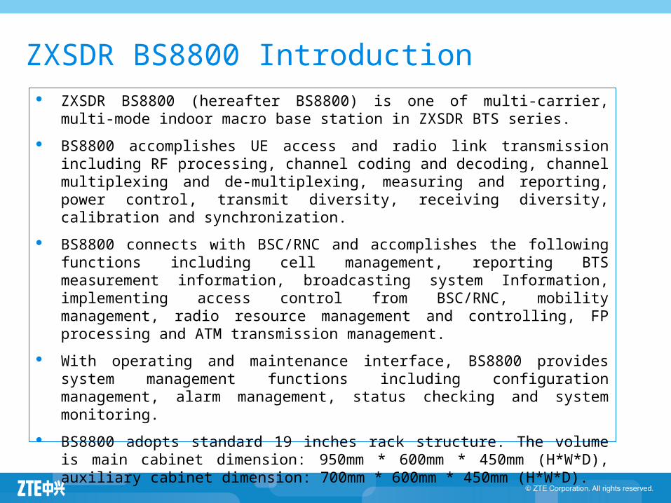
ZXSDR BS8800 Introduction ZXSDR BS8800 (hereafter BS8800) is one of multi-carrier, multi-mode indoor
macro base station in ZXSDR BTS series. BS8800 accomplishes UE access and radio link transmission including RF
processing, channel coding and decoding, channel multiplexing and de-multiplexing, measuring and reporting, power control, transmit diversity, receiving diversity, calibration and synchronization.
BS8800 connects with BSC/RNC and accomplishes the following functions including cell management, reporting BTS measurement information, broadcasting system Information, implementing access control from BSC/RNC, mobility management, radio resource management and controlling, FP processing and ATM transmission management.
With operating and maintenance interface, BS8800 provides system management functions including configuration management, alarm management, status checking and system monitoring.
BS8800 adopts standard 19 inches rack structure. The volume is main cabinet dimension: 950mm * 600mm * 450mm (H*W*D), auxiliary cabinet dimension: 700mm * 600mm * 450mm (H*W*D).
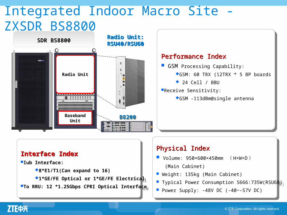
Integrated Indoor Macro Site - ZXSDR BS8800
Radio Unit
BasebandUnit
Radio Unit:RSU40/RSU60
Physical IndexPhysical Index Volume: 950×600×450mm ( H×W×D ) (Main Cabinet) Weight: 135kg (Main Cabinet) Typical Power Consumption S666:735W(RSU60) Power Supply: -48V DC (-40~-57V DC)
Performance IndexPerformance Index GSM Processing Capability:
GSM: 60 TRX (12TRX * 5 BP boards 24 Cell / BBU
Receive Sensitivity:GSM -113dBm@single antenna
Interface IndexInterface IndexIub Interface:
8*E1/T1(Can expand to 16)1*GE/FE Optical or 1*GE/FE Electrical
To RRU: 12 *1.25Gbps CPRI Optical Interface
SDR BS8800
B8200
37
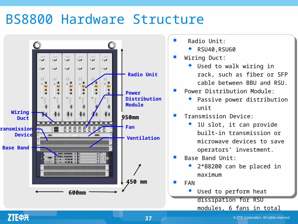
Radio Unit: RSU40,RSU60
Wiring Duct: Used to walk wiring in rack, such
as fiber or SFP cable between BBU and RSU.
Power Distribution Module: Passive power distribution unit
Transmission Device: 1U slot, it can provide built-in
transmission or microwave devices to save operators’ investment.
Base Band Unit: 2*B8200 can be placed in
maximum FAN
Used to perform heat dissipation for RSU modules, 6 fans in total
BS8800 Hardware Structure
950mm
600mm
450 mm
Radio Unit
Power Distribution Module
WiringDuct
TransmissionDevice Ventilation
Base Band
Fan
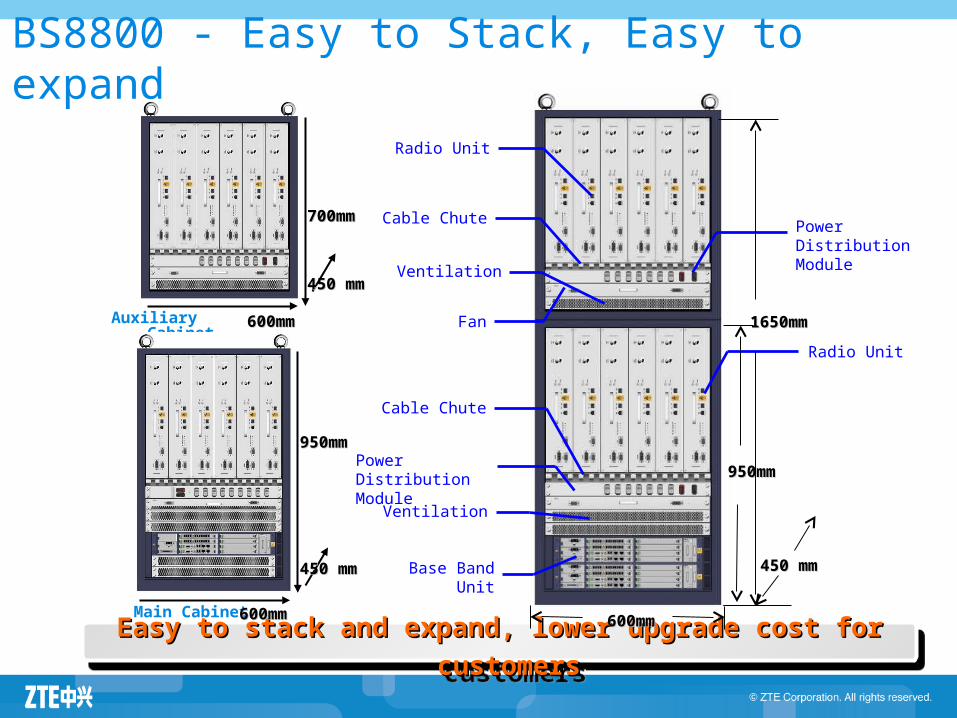
Easy to stack and expand, lower upgrade cost for customersEasy to stack and expand, lower upgrade cost for customers
BS8800 - Easy to Stack, Easy to expand
1650mm1650mm
450 mm450 mm
600mm600mm
Power DistributionModule
Cable Chute
Base Band Unit
950mm950mmPower DistributionModule
Cable Chute
Radio Unit
Auxiliary Cabinet Fan
Radio Unit
Ventilation
Main Cabinet
950mm950mm
600mm600mm
450 mm450 mm
600mm600mm
450 mm450 mm
700mm700mm
Ventilation
Agenda
ZXSDR BTS Family Introduction ZXSDR BS8700 ZXSDR BS8800 ZXSDR BS8900 ZXSDR BS8906 ZXSDR BTS Work Principle ZXSDR BTS Operation and Maintenance
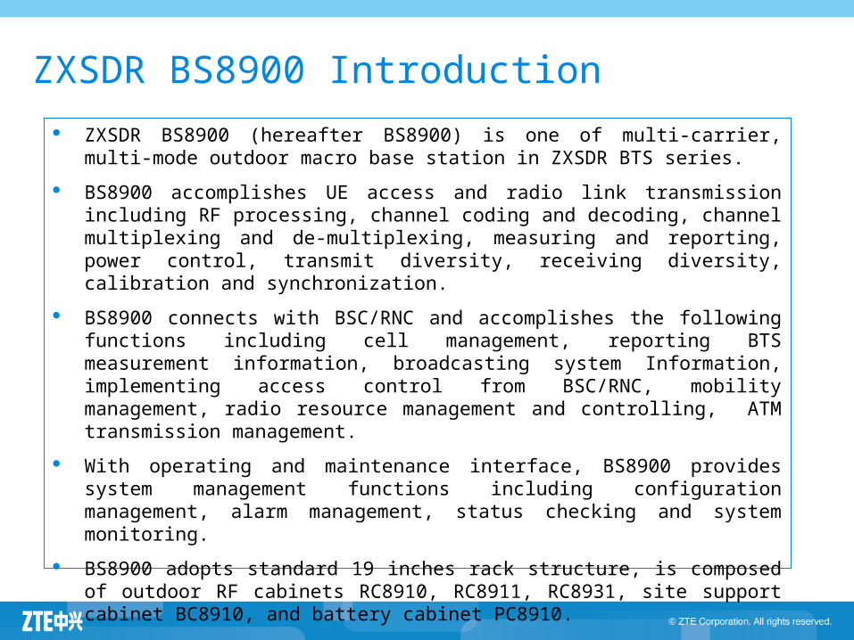
ZXSDR BS8900 Introduction ZXSDR BS8900 (hereafter BS8900) is one of multi-carrier, multi-mode outdoor
macro base station in ZXSDR BTS series. BS8900 accomplishes UE access and radio link transmission including RF
processing, channel coding and decoding, channel multiplexing and de-multiplexing, measuring and reporting, power control, transmit diversity, receiving diversity, calibration and synchronization.
BS8900 connects with BSC/RNC and accomplishes the following functions including cell management, reporting BTS measurement information, broadcasting system Information, implementing access control from BSC/RNC, mobility management, radio resource management and controlling, ATM transmission management.
With operating and maintenance interface, BS8900 provides system management functions including configuration management, alarm management, status checking and system monitoring.
BS8900 adopts standard 19 inches rack structure, is composed of outdoor RF cabinets RC8910, RC8911, RC8931, site support cabinet BC8910, and battery cabinet PC8910.
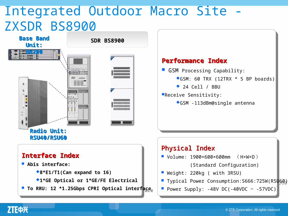
Integrated Outdoor Macro Site - ZXSDR BS8900
Radio Unit:RSU40/RSU60
Physical IndexPhysical Index Volume: 1900×600×600mm ( H×W×D )
(Standard Configuration) Weight: 220kg ( with 3RSU) Typical Power Consumption:S666:725W(RSU60) Power Supply: -48V DC(-40VDC ~ -57VDC)
Interface IndexInterface Index Abis interface:
8*E1/T1(Can expand to 16)1*GE Optical or 1*GE/FE Electrical
To RRU: 12 *1.25Gbps CPRI Optical interface
SDR BS8900Base Band Unit:B8200
Performance IndexPerformance Index GSM Processing Capability:
GSM: 60 TRX (12TRX * 5 BP boards) 24 Cell / BBU
Receive Sensitivity:GSM -113dBm@single antenna
42
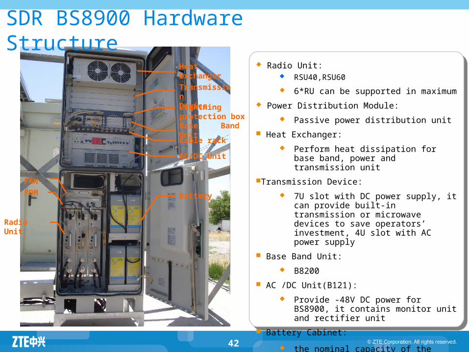
SDR BS8900 Hardware Structure Radio Unit:
RSU40,RSU60 6*RU can be supported in maximum
Power Distribution Module: Passive power distribution unit
Heat Exchanger: Perform heat dissipation for base band,
power and transmission unitTransmission Device:
7U slot with DC power supply, it can provide built-in transmission or microwave devices to save operators’ investment, 4U slot with AC power supply
Base Band Unit: B8200
AC /DC Unit(B121): Provide -48V DC power for BS8900, it
contains monitor unit and rectifier unit Battery Cabinet:
the nominal capacity of the built-in batteries is 300Ah
Heat Exchanger
TransmissionDevice
Base Band Unit
AC/DC Unit
PDM
Lightning protection box
Cable rack
FAN
Battery
Radio Unit
Agenda
ZXSDR BTS Family Introduction ZXSDR BS8700 ZXSDR BS8800 ZXSDR BS8900 ZXSDR BS8900A ZXSDR BS8906 ZXSDR BTS Work Principle ZXSDR BTS Operation and Maintenance
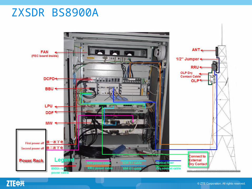
ZXSDR BS8900A

Hardware Architecture
BBU performs Abis/Iub interface functions, signaling processing,baseband processing, remote and local O&M functions, working status monitoring, and alarm functions.
RRU performs terminal access and RF link transmission function through Um/Uu interface.
GPS antenna
SAE1/T1
BSC/RNC
IQ switching
IQ GE
RRU
FAM
PM
Abis/IubClock
GE/FE
GE
UBPG/ BPC
FS GEswitching
CC
Fiber
BBU
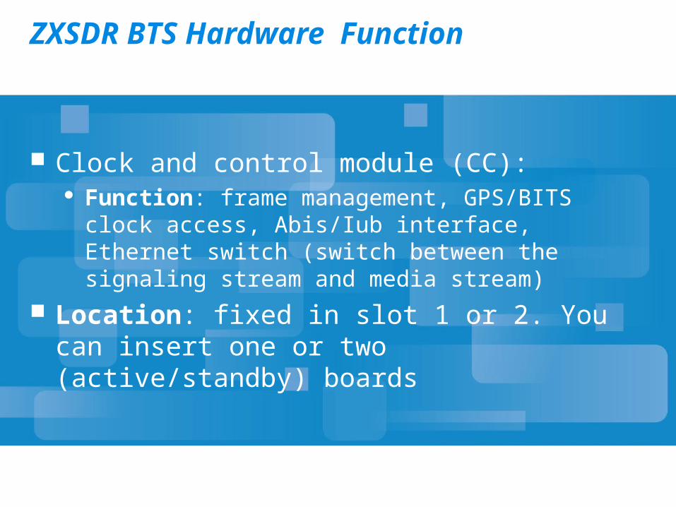
ZXSDR BTS Hardware Function
Clock and control module (CC): Function: frame management, GPS/BITS clock access,
Abis/Iub interface, Ethernet switch (switch between the signaling stream and media stream)
Location: fixed in slot 1 or 2. You can insert one or two (active/standby) boards
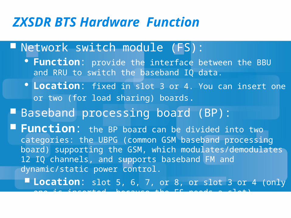
ZXSDR BTS Hardware Function Network switch module (FS):
Function: provide the interface between the BBU and RRU to switch the baseband IQ data.
Location: fixed in slot 3 or 4. You can insert one or two (for load sharing) boards.
Baseband processing board (BP): Function: the BP board can be divided into two categories: the UBPG
(common GSM baseband processing board) supporting the GSM, which modulates/demodulates 12 IQ channels, and supports baseband FM and dynamic/static power control. Location: slot 5, 6, 7, or 8, or slot 3 or 4 (only one is inserted,
because the FS needs a slot).
ZXSDR BTS Hardware Function
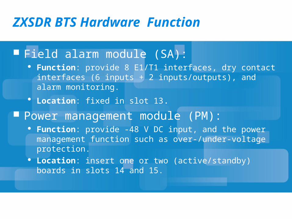
Field alarm module (SA): Function: provide 8 E1/T1 interfaces, dry contact interfaces (6
inputs + 2 inputs/outputs), and alarm monitoring. Location: fixed in slot 13.
Power management module (PM): Function: provide -48 V DC input, and the power management
function such as over-/under-voltage protection. Location: insert one or two (active/standby) boards in slots 14 and
15.

Configuration of ZXSDR
OMCR Data Configuration
OMCB Data Configuration
OMCR Data Configuration
Task Purpose
Set the BSC global resource configuration parameters. Configure the Abis interface board and OMCB interface
bard of the BSC. Configure the Abis interface, OMCB interface, IP interface
of the BSC virtual address. Configure the logical site and radio parameters of the SDR
OMCR Data Configuration
Task Preparation The operating system, database and iOMCRV6.20 network
management including the OMCR and OMCB are correctly installed and run normally.
The A interface and Gb interface of the iBSC are connected, and the dialing test is normal.
IP addresses of the SDR site, Abis interface on the BSC, OMCB interface, OMCB interface and the virtual IP address of the BSC are planned. The module number corresponding to the SDR on the BSC and Abis interface position are also planned.