Embed Size (px)
Citation preview
SCHOOL OF ARCHITECTURE, BUILDING AND DESIGN
BACHELOR OF SCIENCE (HONS) IN ARCHITECTURE
BUILDING SERVICES
[BLD 60903 / ARC 2423]
PROJECT 2:
BUILDING SERVICES IN PUBLIC
BUILDINGS
PREPARED BY:
PHILIA CHUA YI SIAN 0318936
NATALIE KI XIAO XUAN 0318918
LEE YIH 0318340
RICCO SOH ZHENG WEI 0319890
TAY JIT YING 0319002
TANG WEI XIN 0322731
TUTOR:
MR. SIVARAMAN KUPPUSAMY
TABLE OF CONTENT
NO. CONTENT PAGE
1 Introduction to Building………………………………………………………. 1
Findings and Analysis of Proposed Systems
2 Active Fire Protection System ………………………………………………… 2 - 16
(Prepared by: Lee Yih)
3 Passive Fire Protection System …………………………………………………17 - 30
(Prepared by: Tay Jit Ying)
4 Air Conditioning System ……………………………………………………….31 - 47
(Prepared by: Natalie Ki Xiao Xuan)
5 Mechanical (and Natural) Ventilation System ………………………………….48 - 60
(Prepared by: Philia Chua Yi Sian and Ricco Soh Zheng Wei)
6 Mechanical Transportation System ……………………………………………..61- 72
(Prepared by: Tang Wei Xin)
7 Conclusion………………………………………………………………………. 73
8 References……………………………………………………………………….74 - 77
9 Appendix………………………………………………………………………... 78
1
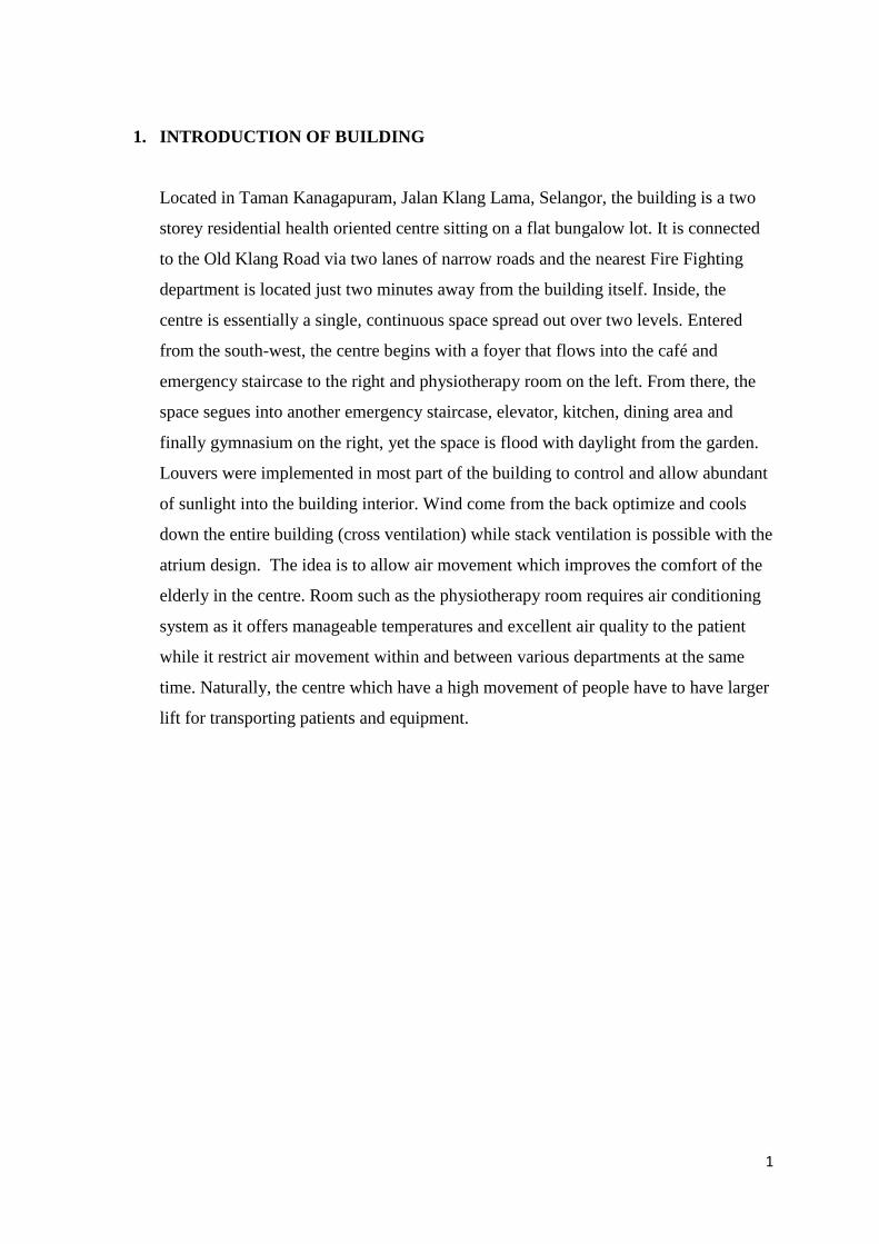
1. INTRODUCTION OF BUILDING
Located in Taman Kanagapuram, Jalan Klang Lama, Selangor, the building is a two
storey residential health oriented centre sitting on a flat bungalow lot. It is connected
to the Old Klang Road via two lanes of narrow roads and the nearest Fire Fighting
department is located just two minutes away from the building itself. Inside, the
centre is essentially a single, continuous space spread out over two levels. Entered
from the south-west, the centre begins with a foyer that flows into the café and
emergency staircase to the right and physiotherapy room on the left. From there, the
space segues into another emergency staircase, elevator, kitchen, dining area and
finally gymnasium on the right, yet the space is flood with daylight from the garden.
Louvers were implemented in most part of the building to control and allow abundant
of sunlight into the building interior. Wind come from the back optimize and cools
down the entire building (cross ventilation) while stack ventilation is possible with the
atrium design. The idea is to allow air movement which improves the comfort of the
elderly in the centre. Room such as the physiotherapy room requires air conditioning
system as it offers manageable temperatures and excellent air quality to the patient
while it restrict air movement within and between various departments at the same
time. Naturally, the centre which have a high movement of people have to have larger
lift for transporting patients and equipment.
2
FINDINGS AND ANALYSIS OF PROPOSED SYSTEMS
2. ACTIVE FIRE PROTECTION SYSTEM (Prepared by: Lee Yih)
2.1 LITERATURE REVIEW
Active fire protection is a group of systems that work efficiently during an
outbreak of fire when certain amount of action or motion is carried out. The
advantages of this system is that it avoids fire spreading by slowing down the fire
development or put out small amount of fire, thus, improves the accessibility for
the occupants to move around in the event. It also provides better protection of
infrastructure installed in the building. Whereas the disadvantages of this fire
protection system is that it does not extinguish large fires. It requires complex
equipments or systems to be installed and destratification of smoke layers which
lead to reduction of visibility happens when it’s activated.
The main purpose of active fire protection is divided into three categories:
1. to detect
2. to notify
3. fire fighting
With active fire protection installed, its sensitivity allows it to detect the presence
of fire in a building precisely and as prompt as possible so that early actions could
be taken when the accident is still controllable. This is done by efficient locating
sources of smoke, heat or flame through detectors.
Detection of fire triggers activation of fire alarm and emergency services at the
right time to notify occupants that evacuation out of building or to the
predetermined assembly point is necessary. Its activation happens in advance to
allocate sufficient amount of time for occupants to carry out the evacuation.
Attempt on fire-fighting measures are through automated system like water
sprinklers and fire suppression, as well as manual system like fire extinguishers or
fire hose reels used by the fire fighters. This process is further divided into water
3
based system and non-water based system. Nevertheless, the real purpose behind
this is still to slow large fires and to allocate more time for escaping.
2.2 OVERVIEW
Active fire protection systems interact with their surroundings by operating certain
mechanism to control or extinguish a fire, or opening a vent to allow assisted
natural ventilation or to evacuate users out of the building. The components of this
system are flexible to be replaced according to user’s priority and preferences
during the event of fire. Different components are installed depending on the
scales and types of buildings.
In this elderly centre, majority of the elderlies are above 65 years old and most of
them are either depending on walkers, completely immobile or completely
unconscious. Hence, mobility, health issues, mental stability have became the
consideration factors while designing the active fire protection systems as
elderlies tend to be more sensitive and fragile. Improper design might cause chaos,
mental disturbance and physical injuries which may be life threatening to the
elderlies.
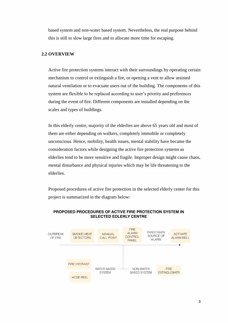
Proposed procedures of active fire protection in the selected elderly center for this
project is summarized in the diagram below:
4
2.3 PROPOSAL OF SYSTEMS
2.3.1 DETECTION
2.3.1.1 Smoke and Heat Detectors
Optical Smoke Detector
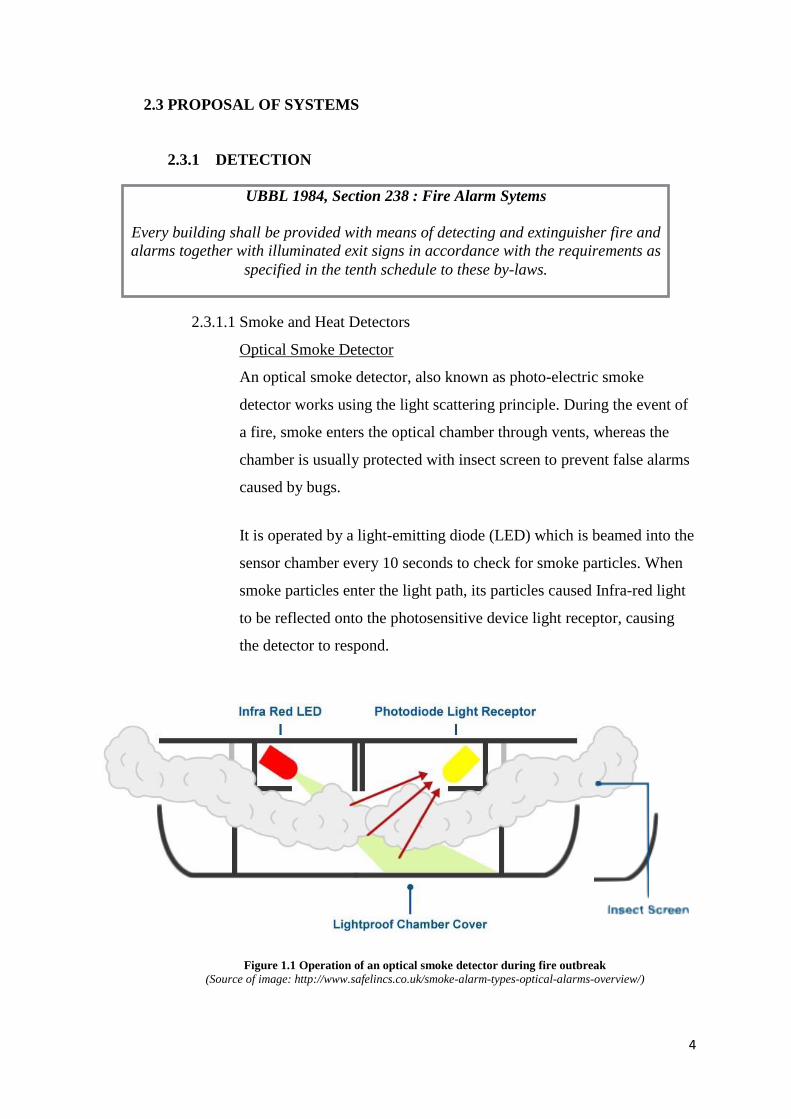
An optical smoke detector, also known as photo-electric smoke
detector works using the light scattering principle. During the event of
a fire, smoke enters the optical chamber through vents, whereas the
chamber is usually protected with insect screen to prevent false alarms
caused by bugs.
It is operated by a light-emitting diode (LED) which is beamed into the
sensor chamber every 10 seconds to check for smoke particles. When
smoke particles enter the light path, its particles caused Infra-red light
to be reflected onto the photosensitive device light receptor, causing
the detector to respond.
UBBL 1984, Section 238 : Fire Alarm Sytems
Every building shall be provided with means of detecting and extinguisher fire and
alarms together with illuminated exit signs in accordance with the requirements as
specified in the tenth schedule to these by-laws.
Figure 1.1 Operation of an optical smoke detector during fire outbreak
(Source of image: http://www.safelincs.co.uk/smoke-alarm-types-optical-alarms-overview/)
5
Proposal and Justification
This type of detector is suitable for the elderly center as it responds
faster to fire due to its sensitivity at detecting large particles of smoke
and is less prone to false alarms. Also, its small size ensures aesthetic
installations rather than becoming an eyesore to the elderlies. This
detector is proposed to be applied in all spaces except for kitchen and
outdoor spaces. However, tobacco smoke and steam would trigger
false alarms and hence smoking has to be prohibited inside the
building.
Fixed cum RoR Heat Detector
The function of a heat detector is to minimize property damage by
reacting to the change in temperature during a fire outbreak. They
activate the alarm system to notify occupants of potential fire in the
kitchen. To increase efficiency of heat alarm, it can also be linked with
smoke detectors in the fire control system.
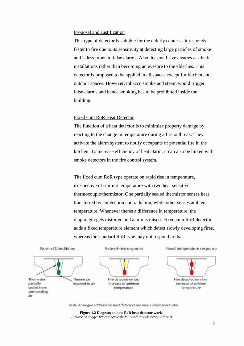
The fixed cum RoR type operate on rapid rise in temperature,
irrespective of starting temperature with two heat sensitive
thermocouple/thermistor. One partially sealed thermistor senses heat
transferred by convection and radiation, while other senses ambient
temperature. Whenever theres a difference in temperature, the
diaphragm gets distorted and alarm is raised. Fixed cum RoR detector
adds a fixed temperature element which detect slowly developing fires,
whereas the standard RoR type may not respond to that.
Figure 1.2 Diagram on how RoR heat detector works
(Source of image: http://electricalinfo.in/tech/fire-detection-alarm/)
6
Proposal and Justification
Fixed cum RoR heat detector is proposed at the kitchen in the elderly
centre.
Due to the function of kitchen which is often filled with smoke when
cooking is carried out, false alarms would be caused if optical smoke
detectors are installed. In contrary, heat detectors will prevent this to
happen as it only detect abnormally high temperatures or rapid
increases in temperature. Besides, all detectors proposed in the
building are combined alarms with sensors, hence, audible signals
would be produced from the detectors when it’s activated.
2.3.2 NOTIFICATION
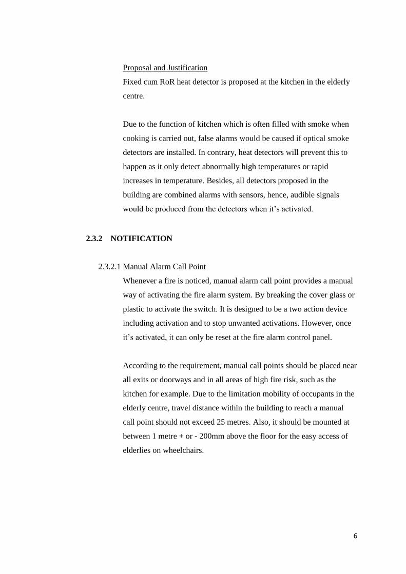
2.3.2.1 Manual Alarm Call Point
Whenever a fire is noticed, manual alarm call point provides a manual
way of activating the fire alarm system. By breaking the cover glass or
plastic to activate the switch. It is designed to be a two action device
including activation and to stop unwanted activations. However, once
it’s activated, it can only be reset at the fire alarm control panel.
According to the requirement, manual call points should be placed near
all exits or doorways and in all areas of high fire risk, such as the
kitchen for example. Due to the limitation mobility of occupants in the
elderly centre, travel distance within the building to reach a manual
call point should not exceed 25 metres. Also, it should be mounted at
between 1 metre + or - 200mm above the floor for the easy access of
elderlies on wheelchairs.
7
2.3.2.2 Fire Alarm System
A fire alarm system is intended to produce alert signals at a
sufficiently early stage so that occupants who are at risk can be
made safe either by evacuation before the escape routes becomes
Figure 1.3 Example of manual alarm call point
(Source of image: http://www.cqr.co.uk/access/fp2-
manual-call-point/)
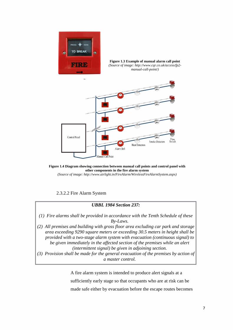
Figure 1.4 Diagram showing connection between manual call points and control panel with
other components in the fire alarm system
(Source of image: http://www.airlight.in/FireAlarm/WirelessFireAlarmSystem.aspx)
UBBL 1984 Section 237:
(1) Fire alarms shall be provided in accordance with the Tenth Schedule of these
By-Laws.
(2) All premises and building with gross floor area excluding car park and storage
area exceeding 9290 square meters or exceeding 30.5 meters in height shall be
provided with a two-stage alarm system with evacuation (continuous signal) to
be given immediately in the affected section of the premises while an alert
(intermittent signal) be given in adjoining section.
(3) Provision shall be made for the general evacuation of the premises by action of
a master control.
8
smoke-logged, or by extinguishing the fire and at the same time
minimising property damage.
Two Stage System
It is a system which produces distinct alert signal that first advises
the staff of the fire emergency, with its coded signal why is only
apparent to designated building staff. The staff are expected to
immediately investigate source of the alarm, and to activate the
alarm signal if a fire exists. After a predetermined period of time
(usually five minutes), the coded signal will automatically set off.
On the other hand, if it’s a false alarm, staff can silence the coded
alert signal and reset the system.
Proposal and Justification
Two stage fire alarm system is proposed in this elderly centre as
evacuation of the occupants is difficult and could be physically
harmful due to the elderlies’ limited mobility. Besides, blaring
alarm sound could possible cause undue distress to the elderlies as
they tend to be more sensitive to the environment.
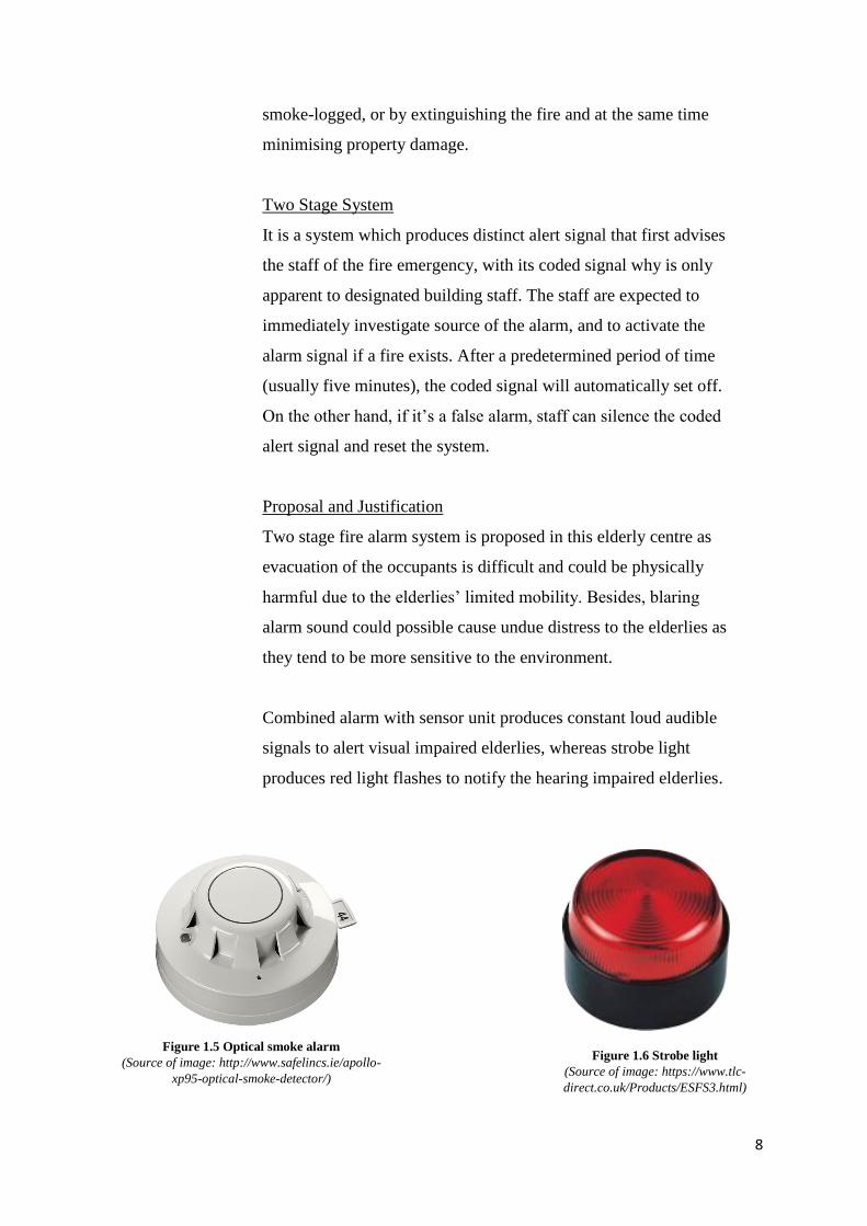
Combined alarm with sensor unit produces constant loud audible
signals to alert visual impaired elderlies, whereas strobe light
produces red light flashes to notify the hearing impaired elderlies.
Figure 1.5 Optical smoke alarm
(Source of image: http://www.safelincs.ie/apollo-
xp95-optical-smoke-detector/)
Figure 1.6 Strobe light
(Source of image: https://www.tlc-
direct.co.uk/Products/ESFS3.html)
9
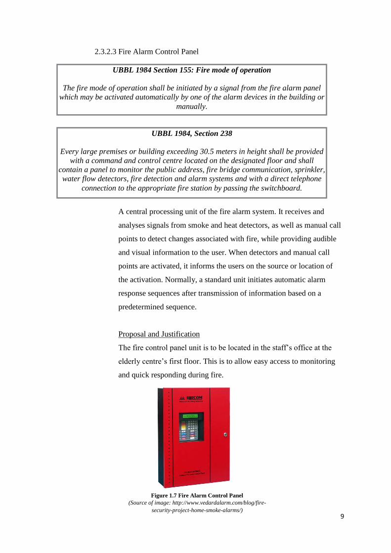
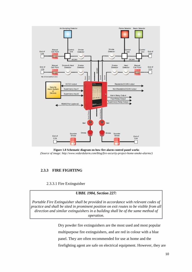
2.3.2.3 Fire Alarm Control Panel
A central processing unit of the fire alarm system. It receives and
analyses signals from smoke and heat detectors, as well as manual call
points to detect changes associated with fire, while providing audible
and visual information to the user. When detectors and manual call
points are activated, it informs the users on the source or location of
the activation. Normally, a standard unit initiates automatic alarm
response sequences after transmission of information based on a
predetermined sequence.
Proposal and Justification
The fire control panel unit is to be located in the staff’s office at the
elderly centre’s first floor. This is to allow easy access to monitoring
and quick responding during fire.
UBBL 1984 Section 155: Fire mode of operation
The fire mode of operation shall be initiated by a signal from the fire alarm panel
which may be activated automatically by one of the alarm devices in the building or
manually.
UBBL 1984, Section 238
Every large premises or building exceeding 30.5 meters in height shall be provided
with a command and control centre located on the designated floor and shall
contain a panel to monitor the public address, fire bridge communication, sprinkler,
water flow detectors, fire detection and alarm systems and with a direct telephone
connection to the appropriate fire station by passing the switchboard.
Figure 1.7 Fire Alarm Control Panel
(Source of image: http://www.vedardalarm.com/blog/fire-
security-project-home-smoke-alarms/)
10
2.3.3 FIRE FIGHTING
2.3.3.1 Fire Extinguisher
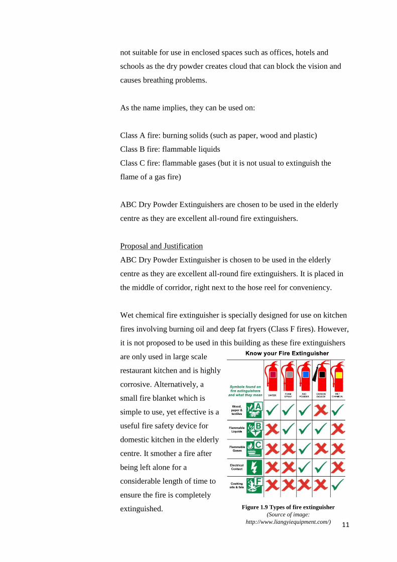
Dry powder fire extinguishers are the most used and most popular
multipurpose fire extinguishers, and are red in colour with a blue
panel. They are often recommended for use at home and the
firefighting agent are safe on electrical equipment. However, they are
Figure 1.8 Schematic diagram on how fire alarm control panel works
(Source of image: http://www.vedardalarm.com/blog/fire-security-project-home-smoke-alarms/)
UBBL 1984, Section 227:
Portable Fire Extinguisher shall be provided in accordance with relevant codes of
practice and shall be sited in prominent position on exit routes to be visible from all
direction and similar extinguishers in a building shall be of the same method of
operation.
11
not suitable for use in enclosed spaces such as offices, hotels and
schools as the dry powder creates cloud that can block the vision and
causes breathing problems.
As the name implies, they can be used on:
Class A fire: burning solids (such as paper, wood and plastic)
Class B fire: flammable liquids
Class C fire: flammable gases (but it is not usual to extinguish the
flame of a gas fire)
ABC Dry Powder Extinguishers are chosen to be used in the elderly
centre as they are excellent all-round fire extinguishers.
Proposal and Justification
ABC Dry Powder Extinguisher is chosen to be used in the elderly
centre as they are excellent all-round fire extinguishers. It is placed in
the middle of corridor, right next to the hose reel for conveniency.
Wet chemical fire extinguisher is specially designed for use on kitchen
fires involving burning oil and deep fat fryers (Class F fires). However,
it is not proposed to be used in this building as these fire extinguishers
are only used in large scale
restaurant kitchen and is highly
corrosive. Alternatively, a
small fire blanket which is
simple to use, yet effective is a
useful fire safety device for
domestic kitchen in the elderly
centre. It smother a fire after
being left alone for a
considerable length of time to
ensure the fire is completely
extinguished. Figure 1.9 Types of fire extinguisher
(Source of image:
http://www.liangyiequipment.com/)
12
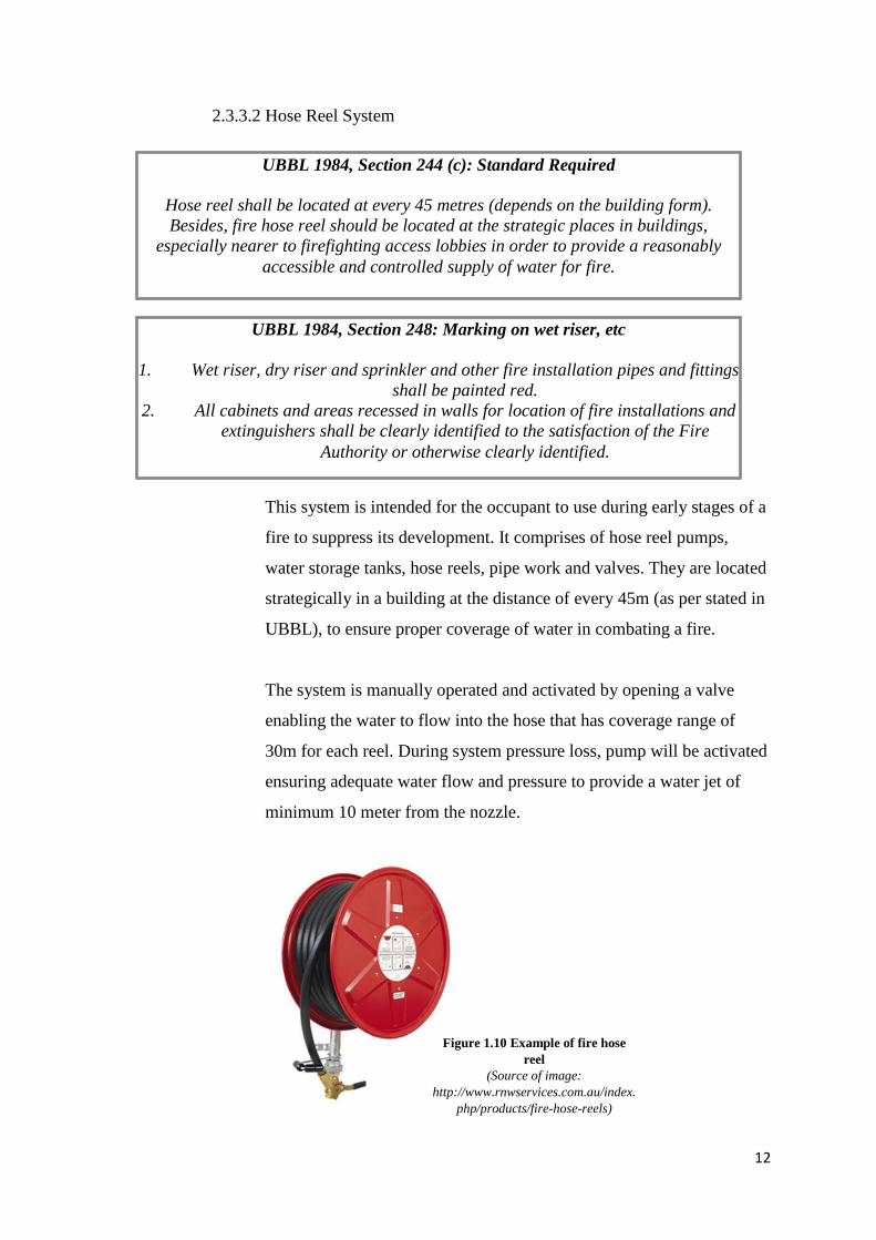
2.3.3.2 Hose Reel System
This system is intended for the occupant to use during early stages of a
fire to suppress its development. It comprises of hose reel pumps,
water storage tanks, hose reels, pipe work and valves. They are located
strategically in a building at the distance of every 45m (as per stated in
UBBL), to ensure proper coverage of water in combating a fire.
The system is manually operated and activated by opening a valve
enabling the water to flow into the hose that has coverage range of
30m for each reel. During system pressure loss, pump will be activated
ensuring adequate water flow and pressure to provide a water jet of
minimum 10 meter from the nozzle.
UBBL 1984, Section 248: Marking on wet riser, etc
1. Wet riser, dry riser and sprinkler and other fire installation pipes and fittings
shall be painted red.
2. All cabinets and areas recessed in walls for location of fire installations and
extinguishers shall be clearly identified to the satisfaction of the Fire
Authority or otherwise clearly identified.
UBBL 1984, Section 244 (c): Standard Required
Hose reel shall be located at every 45 metres (depends on the building form).
Besides, fire hose reel should be located at the strategic places in buildings,
especially nearer to firefighting access lobbies in order to provide a reasonably
accessible and controlled supply of water for fire.
Figure 1.10 Example of fire hose
reel
(Source of image:
http://www.rnwservices.com.au/index.
php/products/fire-hose-reels)
13
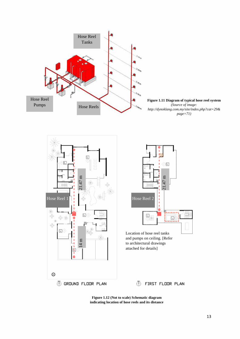
Hose Reels
Hose Reel
Tanks
Hose Reel
Pumps Figure 1.11 Diagram of typical hose reel system
(Source of image:
http://dynoklang.com.my/site/index.php?cat=29&
page=71)
Hose Reel 1 Hose Reel 2
21.4
7 m
21.4
7 m
14
m
Location of hose reel tanks
and pumps on ceiling. [Refer
to architectural drawings
attached for details]
Figure 1.12 (Not to scale) Schematic diagram
indicating location of hose reels and its distance
14
Proposal and Justification
One hose reel is placed at each level in the middle of corridor to ensure
easy access from both direction’s death ends and to be noticed easily
during an emergency. Two of the hose reels are overlapped on top of
each other in each floors to ensure water being transferred efficiently
through vertical piping. Whereas placing of the hose reel tanks and
hose reel pumps on top of ceiling ensures adequate static pressure to
achieve the required flowrate through gravitational force.
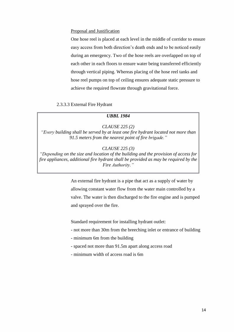
2.3.3.3 External Fire Hydrant
An external fire hydrant is a pipe that act as a supply of water by
allowing constant water flow from the water main controlled by a
valve. The water is then discharged to the fire engine and is pumped
and sprayed over the fire.
Standard requirement for installing hydrant outlet:
- not more than 30m from the breeching inlet or entrance of building
- minimum 6m from the building
- spaced not more than 91.5m apart along access road
- minimum width of access road is 6m
UBBL 1984
CLAUSE 225 (2)
“Every building shall be served by at least one fire hydrant located not more than
91.5 meters from the nearest point of fire brigade.”
CLAUSE 225 (3)
“Depending on the size and location of the building and the provision of access for
fire appliances, additional fire hydrant shall be provided as may be required by the
Fire Authority.”
15
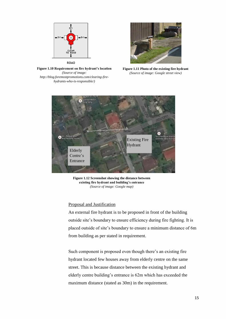
Proposal and Justification
An external fire hydrant is to be proposed in front of the building
outside site’s boundary to ensure efficiency during fire fighting. It is
placed outside of site’s boundary to ensure a minimum distance of 6m
from building as per stated in requirement.
Such component is proposed even though there’s an existing fire
hydrant located few houses away from elderly centre on the same
street. This is because distance between the existing hydrant and
elderly centre building’s entrance is 62m which has exceeded the
maximum distance (stated as 30m) in the requirement.
Figure 1.10 Requirement on fire hydrant’s location
(Source of image:
http://blog.foremostpromotions.com/clearing-fire-
hydrants-who-is-responsible/)
Elderly
Centre’s
Entrance
Existing Fire
Hydrant
Figure 1.12 Screenshot showing the distance between
existing fire hydrant and building’s entrance
(Source of image: Google map)
Figure 1.11 Photo of the existing fire hydrant
(Source of image: Google street view)
16
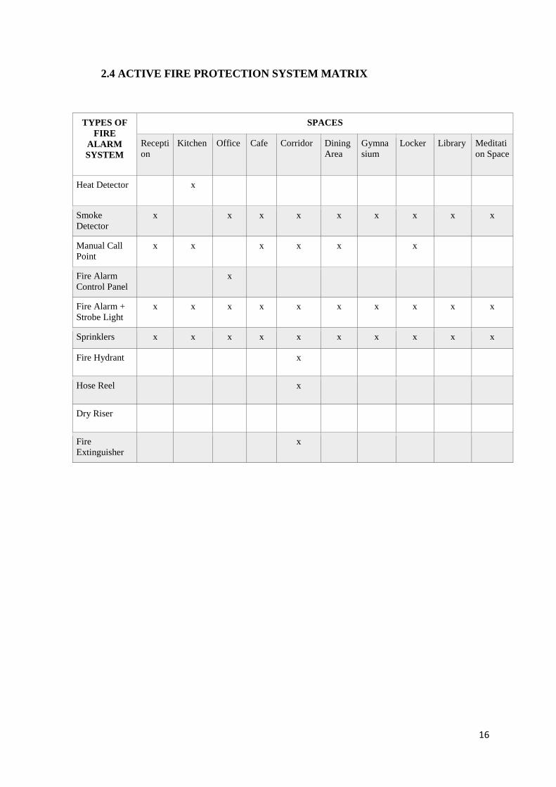
2.4 ACTIVE FIRE PROTECTION SYSTEM MATRIX
TYPES OF
FIRE
ALARM
SYSTEM
SPACES
Recepti
on
Kitchen Office Cafe Corridor Dining
Area
Gymna
sium
Locker Library Meditati
on Space
Heat Detector x
Smoke
Detector
x x x x x x x x x
Manual Call
Point
x x x x x x
Fire Alarm
Control Panel x
Fire Alarm +
Strobe Light
x x x x x x x x x x
Sprinklers x x x x x x x x x x
Fire Hydrant x
Hose Reel x
Dry Riser
Fire
Extinguisher x
17
3. PASSIVE FIRE PROTECTION SYSTEM (Prepared by: Tay Jit Ying)
3.1 LITERATURE REVIEW
Passive fire protection is the primary and one of the most effective method against
fire in a building. Fire protection measure is integrated within the constructional
fabric to provide fire safety and protection against flame, heat and smoke to
maintain structural stability, means of escape and fire protection. Protection
measures are able to achieve by raising the resistance of the structure from fire,
protecting the internal structure, increasing the duration of fire outspread and
minimising structural distortion.
Structural fire protection protect essential structural components (such as
structural steel and joint systems) and prevent the effects of fire and is achieved
with a fireproofing or building the structure out of concrete. Fire barriers,
firewalls, fire partitions, and smoke barriers serves the function of
compartmentation. Fire barriers include fire-rated walls, floors, and ceilings are
utilised to limit the outspread of fire in a building and allow safe egress from the
occupants.
Walls constructed from a fire-rated floor to the fire-rated ceiling continue into
concealed spaces for overall protection. Opening of a fire barrier is installed with
fire doors and windows to maintain its fire resistance. Fire stopping materials are
also used to limit fire from penetrating through fire barriers. Hence, the
application of passive fire protection is critical to the safety and impact of the
occupants and the building itself.
18
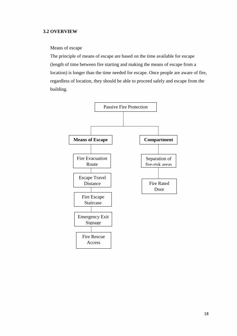
3.2 OVERVIEW
Means of escape
The principle of means of escape are based on the time available for escape
(length of time between fire starting and making the means of escape from a
location) is longer than the time needed for escape. Once people are aware of fire,
regardless of location, they should be able to proceed safely and escape from the
building.
Passive Fire Protection
System
Means of Escape Compartment
Emergency Exit
Signage
Fire Escape
Staircase
Fire Evacuation
Route
Fire Rated
Door
Separation of
fire-risk areas
Escape Travel
Distance
Fire Rescue
Access
19
3.3 PROPOSAL OF SYSTEMS
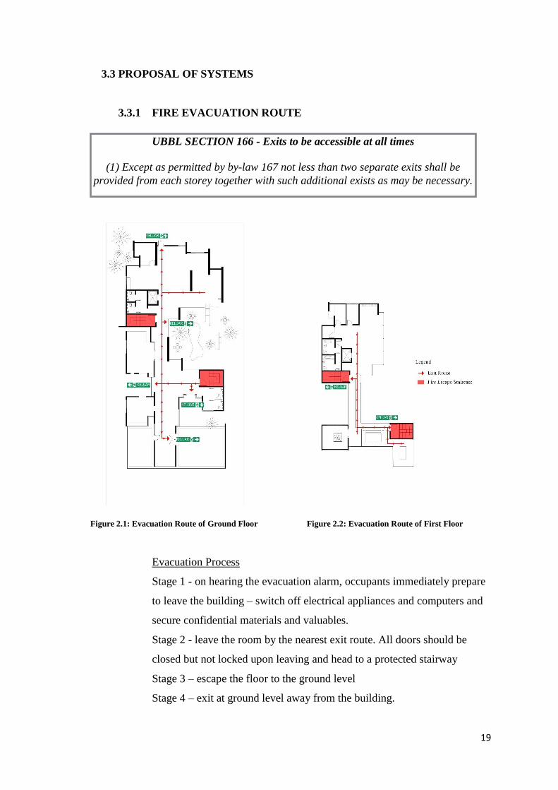
3.3.1 FIRE EVACUATION ROUTE
Evacuation Process
Stage 1 - on hearing the evacuation alarm, occupants immediately prepare
to leave the building – switch off electrical appliances and computers and
secure confidential materials and valuables.
Stage 2 - leave the room by the nearest exit route. All doors should be
closed but not locked upon leaving and head to a protected stairway
Stage 3 – escape the floor to the ground level
Stage 4 – exit at ground level away from the building.
UBBL SECTION 166 - Exits to be accessible at all times
(1) Except as permitted by by-law 167 not less than two separate exits shall be
provided from each storey together with such additional exists as may be necessary.
Figure 2.1: Evacuation Route of Ground Floor Figure 2.2: Evacuation Route of First Floor
20
Design Consideration
1. Two escape staircases in a floor provide means of escape should fire
occur.
2. Signage indicating the escape route is placed throughout the building
as reference at any floor the occupants are located near lift unit.
3. It is assumed that if a fire prevent the occupants from using one of the
staircase, the remaining exit is wife enough to allow all occupants to leave
quickly.
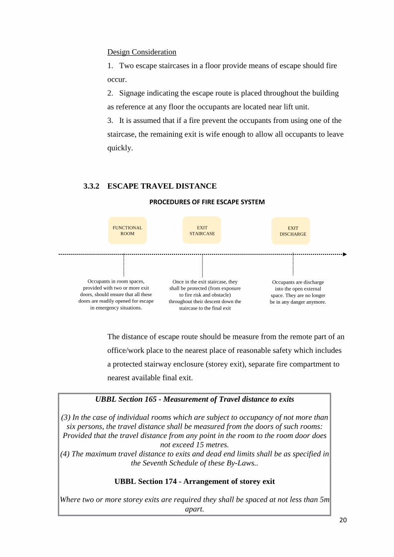
3.3.2 ESCAPE TRAVEL DISTANCE
The distance of escape route should be measure from the remote part of an
office/work place to the nearest place of reasonable safety which includes
a protected stairway enclosure (storey exit), separate fire compartment to
nearest available final exit.
UBBL Section 165 - Measurement of Travel distance to exits
(3) In the case of individual rooms which are subject to occupancy of not more than
six persons, the travel distance shall be measured from the doors of such rooms:
Provided that the travel distance from any point in the room to the room door does
not exceed 15 metres.
(4) The maximum travel distance to exits and dead end limits shall be as specified in
the Seventh Schedule of these By-Laws..
UBBL Section 174 - Arrangement of storey exit
Where two or more storey exits are required they shall be spaced at not less than 5m
apart.
FUNCTIONAL
ROOM
EXIT
STAIRCASE
PROCEDURES OF FIRE ESCAPE SYSTEM
Occupants in room spaces,
provided with two or more exit
doors, should ensure that all these
doors are readily opened for escape
in emergency situations.
Once in the exit staircase, they
shall be protected (from exposure
to fire risk and obstacle)
throughout their descent down the
staircase to the final exit
Occupants are discharge
into the open external
space. They are no longer
be in any danger anymore.
EXIT
DISCHARGE
21
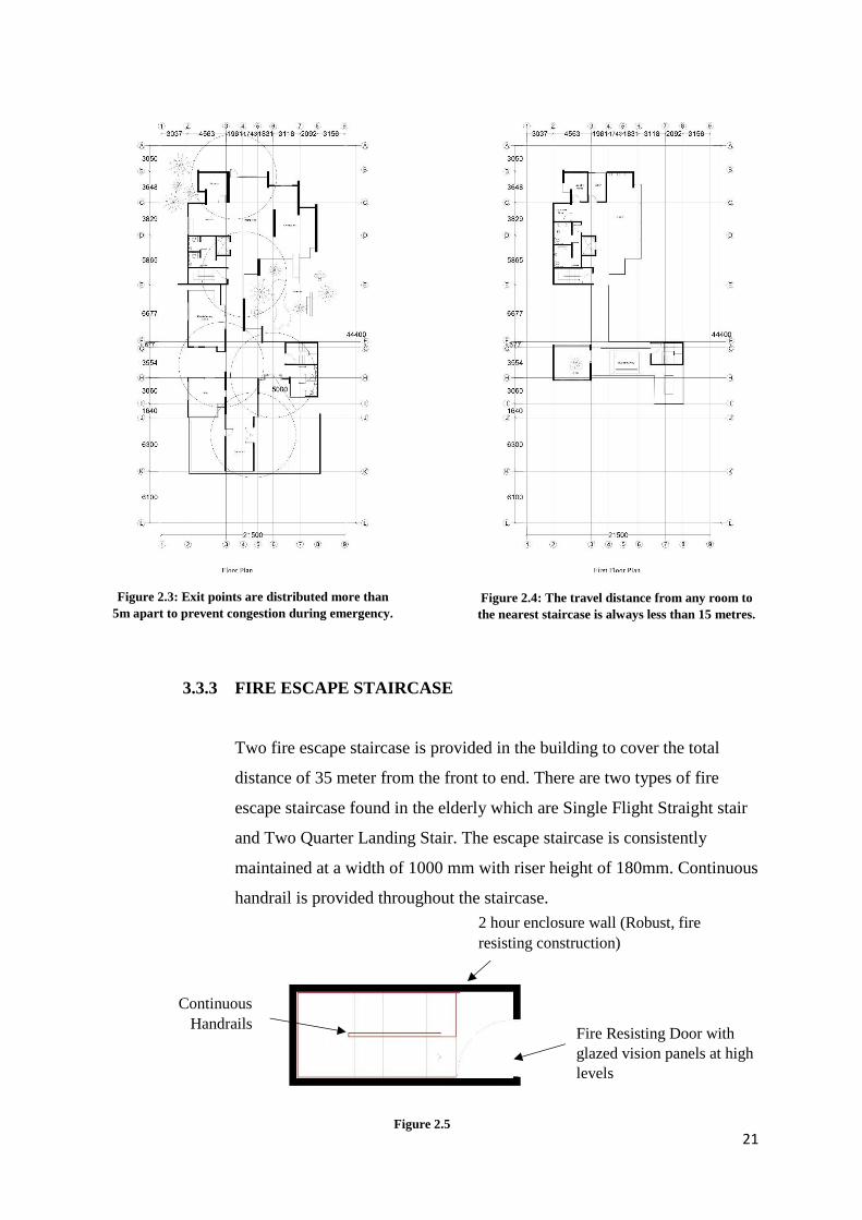
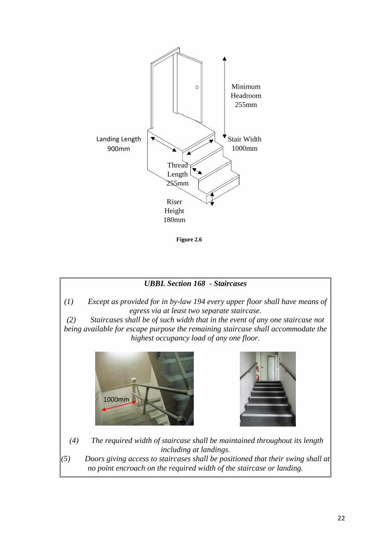
3.3.3 FIRE ESCAPE STAIRCASE
Two fire escape staircase is provided in the building to cover the total
distance of 35 meter from the front to end. There are two types of fire
escape staircase found in the elderly which are Single Flight Straight stair
and Two Quarter Landing Stair. The escape staircase is consistently
maintained at a width of 1000 mm with riser height of 180mm. Continuous
handrail is provided throughout the staircase.
Exit points are distributed more than
5m apart to prevent congestion during
emergency.
Continuous
Handrails Fire Resisting Door with
glazed vision panels at high
levels
2 hour enclosure wall (Robust, fire
resisting construction)
Figure 2.3: Exit points are distributed more than
5m apart to prevent congestion during emergency.
Figure 2.4: The travel distance from any room to
the nearest staircase is always less than 15 metres.
Figure 2.5
22
UBBL Section 168 - Staircases
(1) Except as provided for in by-law 194 every upper floor shall have means of
egress via at least two separate staircase.
(2) Staircases shall be of such width that in the event of any one staircase not
being available for escape purpose the remaining staircase shall accommodate the
highest occupancy load of any one floor.
(4) The required width of staircase shall be maintained throughout its length
including at landings.
(5) Doors giving access to staircases shall be positioned that their swing shall at
no point encroach on the required width of the staircase or landing.
Landing Length
900mm
Stair Width
1000mm
Riser
Height
180mm
Minimum
Headroom
255mm
Thread
Length
255mm
Figure 2.6
23
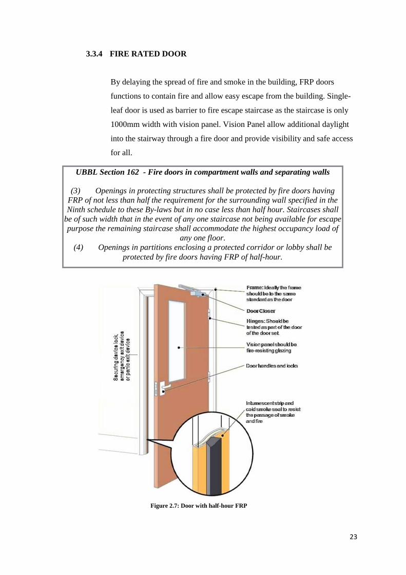
3.3.4 FIRE RATED DOOR
By delaying the spread of fire and smoke in the building, FRP doors
functions to contain fire and allow easy escape from the building. Single-
leaf door is used as barrier to fire escape staircase as the staircase is only
1000mm width with vision panel. Vision Panel allow additional daylight
into the stairway through a fire door and provide visibility and safe access
for all.
Figure 2.7: Door with half-hour FRP
UBBL Section 162 - Fire doors in compartment walls and separating walls
(3) Openings in protecting structures shall be protected by fire doors having
FRP of not less than half the requirement for the surrounding wall specified in the
Ninth schedule to these By-laws but in no case less than half hour. Staircases shall
be of such width that in the event of any one staircase not being available for escape
purpose the remaining staircase shall accommodate the highest occupancy load of
any one floor.
(4) Openings in partitions enclosing a protected corridor or lobby shall be
protected by fire doors having FRP of half-hour.
24
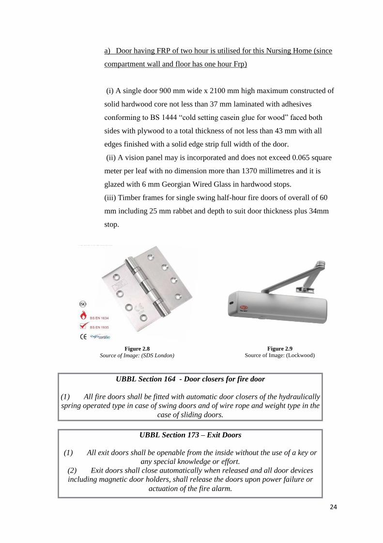
a) Door having FRP of two hour is utilised for this Nursing Home (since
compartment wall and floor has one hour Frp)
(i) A single door 900 mm wide x 2100 mm high maximum constructed of
solid hardwood core not less than 37 mm laminated with adhesives
conforming to BS 1444 “cold setting casein glue for wood” faced both
sides with plywood to a total thickness of not less than 43 mm with all
edges finished with a solid edge strip full width of the door.
(ii) A vision panel may is incorporated and does not exceed 0.065 square
meter per leaf with no dimension more than 1370 millimetres and it is
glazed with 6 mm Georgian Wired Glass in hardwood stops.
(iii) Timber frames for single swing half-hour fire doors of overall of 60
mm including 25 mm rabbet and depth to suit door thickness plus 34mm
stop.
Figure 2.9
Source of Image: (Lockwood) Figure 2.8
Source of Image: (SDS London)
UBBL Section 164 - Door closers for fire door
(1) All fire doors shall be fitted with automatic door closers of the hydraulically
spring operated type in case of swing doors and of wire rope and weight type in the
case of sliding doors.
UBBL Section 173 – Exit Doors
(1) All exit doors shall be openable from the inside without the use of a key or
any special knowledge or effort.
(2) Exit doors shall close automatically when released and all door devices
including magnetic door holders, shall release the doors upon power failure or
actuation of the fire alarm.
25
A label fire door must be hung on steel bearing-type hinges. The use of
steel is necessary since non-ferrous metals become “elastic” at much lower
temperatures, which could allow serious dislocation of the door during a
fire.
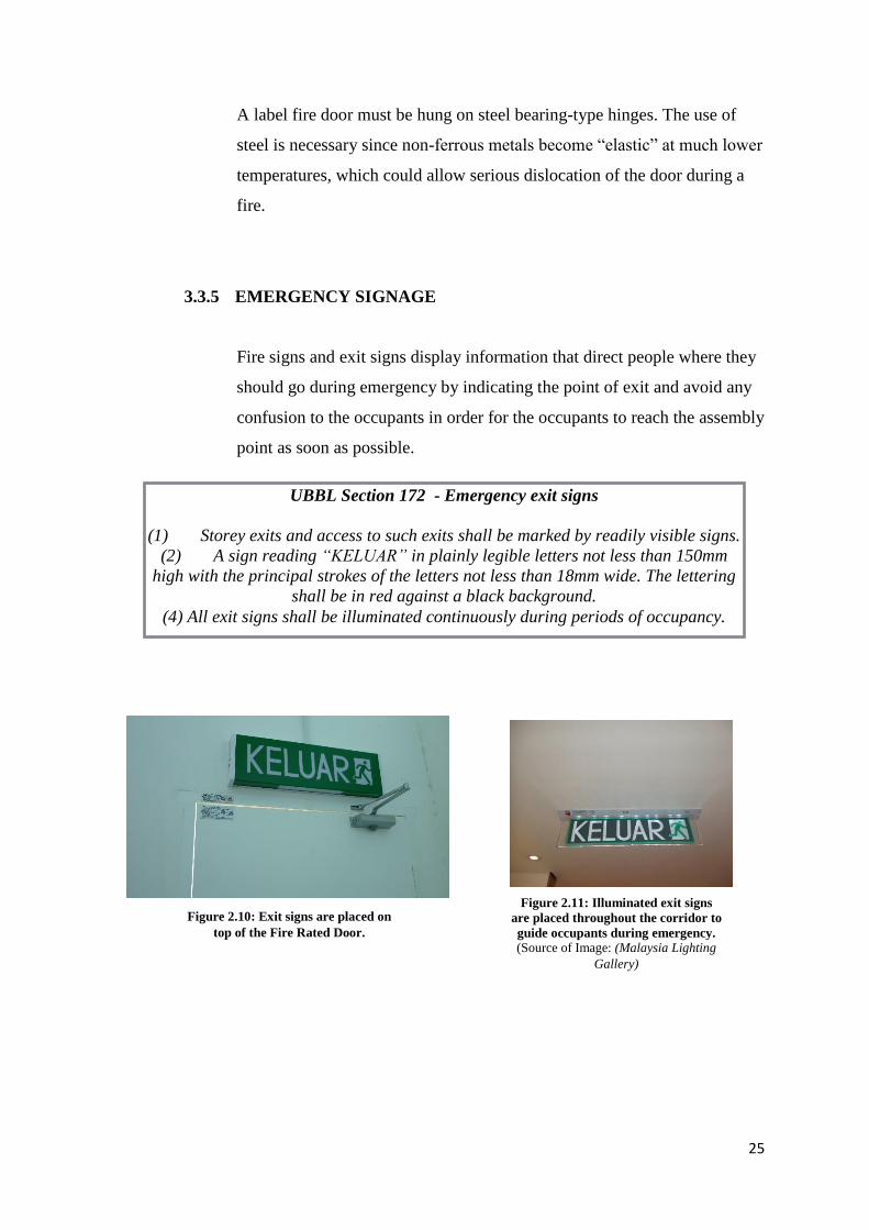
3.3.5 EMERGENCY SIGNAGE
Fire signs and exit signs display information that direct people where they
should go during emergency by indicating the point of exit and avoid any
confusion to the occupants in order for the occupants to reach the assembly
point as soon as possible.
UBBL Section 172 - Emergency exit signs
(1) Storey exits and access to such exits shall be marked by readily visible signs.
(2) A sign reading “KELUAR” in plainly legible letters not less than 150mm
high with the principal strokes of the letters not less than 18mm wide. The lettering
shall be in red against a black background.
(4) All exit signs shall be illuminated continuously during periods of occupancy.
Figure 2.11: Illuminated exit signs
are placed throughout the corridor to
guide occupants during emergency.
(Source of Image: (Malaysia Lighting
Gallery)
Figure 2.10: Exit signs are placed on
top of the Fire Rated Door.
26
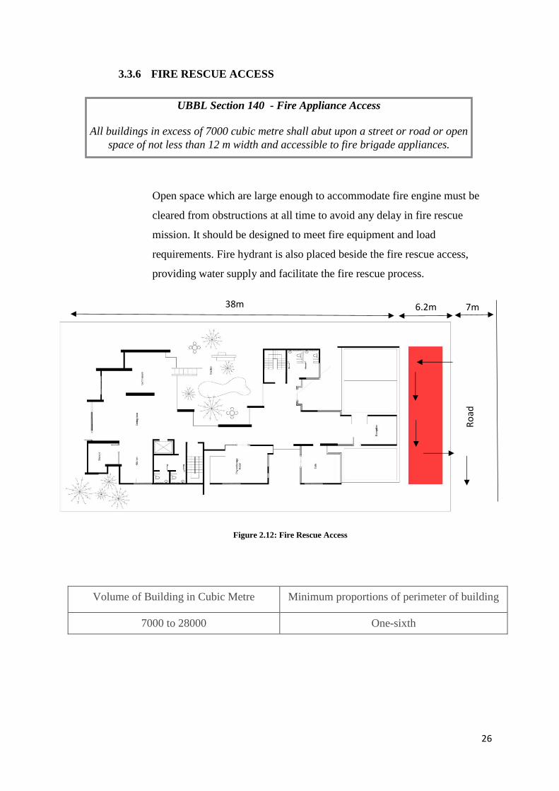
3.3.6 FIRE RESCUE ACCESS
Open space which are large enough to accommodate fire engine must be
cleared from obstructions at all time to avoid any delay in fire rescue
mission. It should be designed to meet fire equipment and load
requirements. Fire hydrant is also placed beside the fire rescue access,
providing water supply and facilitate the fire rescue process.
Volume of Building in Cubic Metre Minimum proportions of perimeter of building
7000 to 28000 One-sixth
UBBL Section 140 - Fire Appliance Access
All buildings in excess of 7000 cubic metre shall abut upon a street or road or open
space of not less than 12 m width and accessible to fire brigade appliances.
Figure 2.12: Fire Rescue Access
Ro
ad
38m 6.2m 7m
27
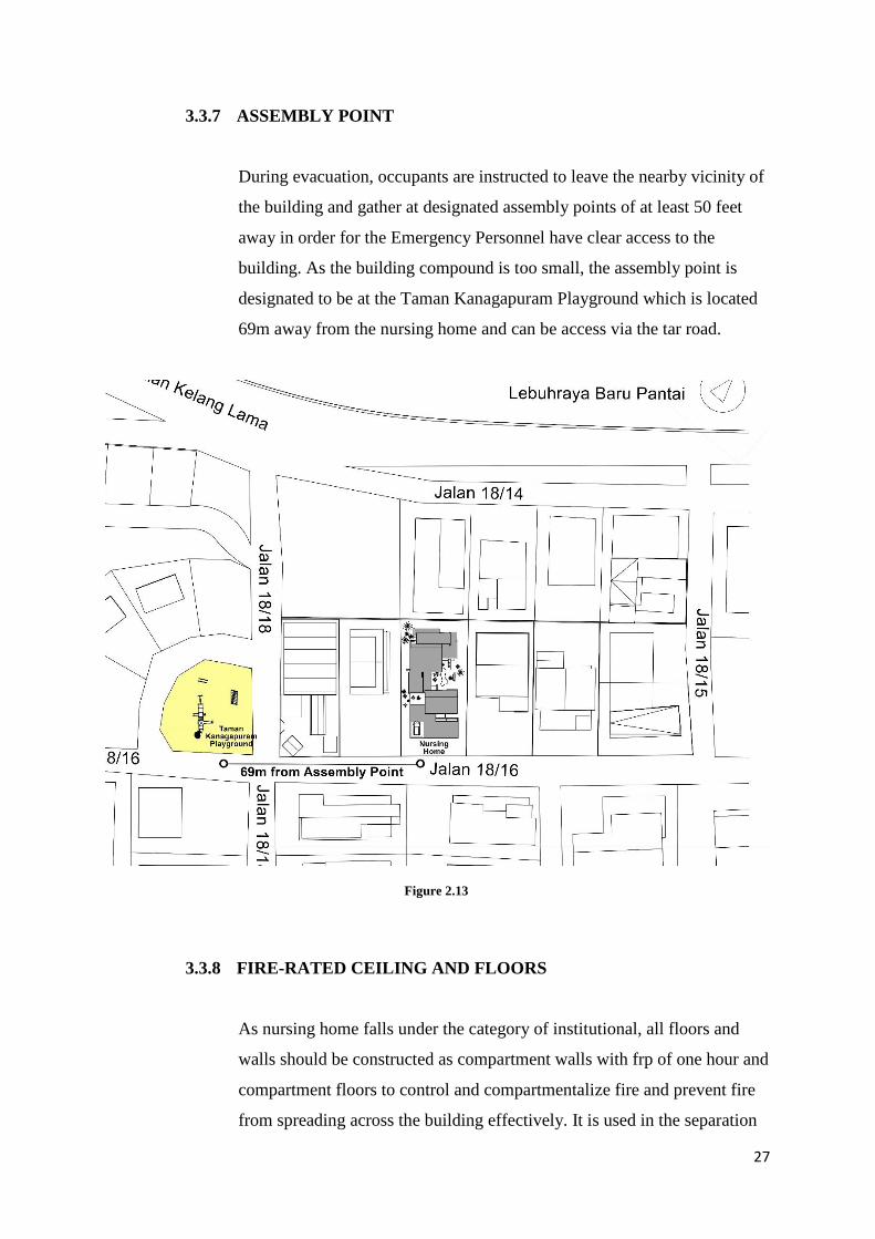
3.3.7 ASSEMBLY POINT
During evacuation, occupants are instructed to leave the nearby vicinity of
the building and gather at designated assembly points of at least 50 feet
away in order for the Emergency Personnel have clear access to the
building. As the building compound is too small, the assembly point is
designated to be at the Taman Kanagapuram Playground which is located
69m away from the nursing home and can be access via the tar road.
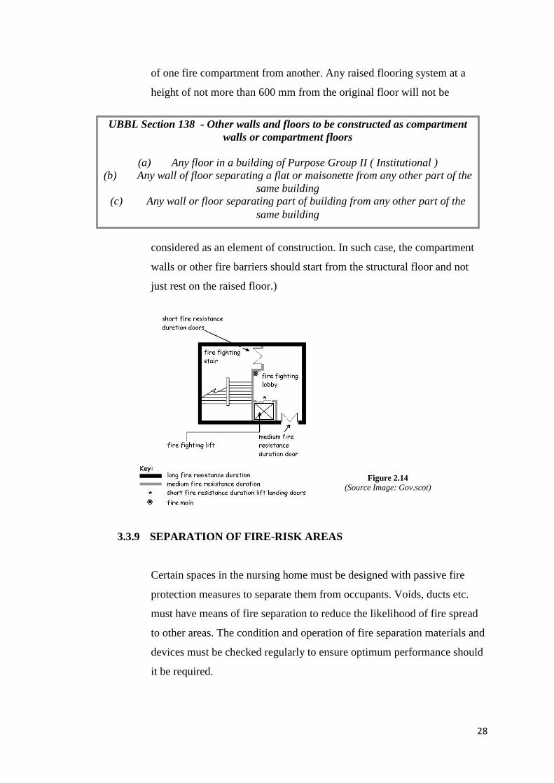
3.3.8 FIRE-RATED CEILING AND FLOORS
As nursing home falls under the category of institutional, all floors and
walls should be constructed as compartment walls with frp of one hour and
compartment floors to control and compartmentalize fire and prevent fire
from spreading across the building effectively. It is used in the separation
Figure 2.13
28
of one fire compartment from another. Any raised flooring system at a
height of not more than 600 mm from the original floor will not be
considered as an element of construction. In such case, the compartment
walls or other fire barriers should start from the structural floor and not
just rest on the raised floor.)
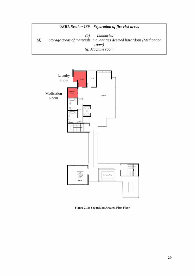
3.3.9 SEPARATION OF FIRE-RISK AREAS
Certain spaces in the nursing home must be designed with passive fire
protection measures to separate them from occupants. Voids, ducts etc.
must have means of fire separation to reduce the likelihood of fire spread
to other areas. The condition and operation of fire separation materials and
devices must be checked regularly to ensure optimum performance should
it be required.
UBBL Section 138 - Other walls and floors to be constructed as compartment
walls or compartment floors
(a) Any floor in a building of Purpose Group II ( Institutional )
(b) Any wall of floor separating a flat or maisonette from any other part of the
same building
(c) Any wall or floor separating part of building from any other part of the
same building
Figure 2.14
(Source Image: Gov.scot)
29
UBBL Section 139 – Separation of fire risk areas
(b) Laundries
(d) Storage areas of materials in quantities deemed hazardous (Medication
room)
(g) Machine room
Figure 2.15: Separation Area on First Floor
Laundry
Room
Medication
Room
30
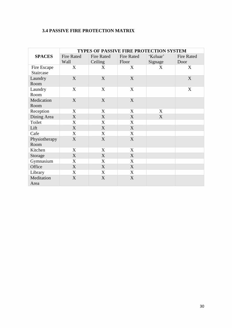
3.4 PASSIVE FIRE PROTECTION MATRIX
SPACES
TYPES OF PASSIVE FIRE PROTECTION SYSTEM
Fire Rated
Wall
Fire Rated
Ceiling
Fire Rated
Floor
‘Keluar’
Signage
Fire Rated
Door
Fire Escape
Staircase
X X X X X
Laundry
Room
X X X X
Laundry
Room
X X X X
Medication
Room
X X X
Reception X X X X
Dining Area X X X X
Toilet X X X
Lift X X X
Cafe X X X
Physiotherapy
Room
X X X
Kitchen X X X
Storage X X X
Gymnasium X X X
Office X X X
Library X X X
Meditation
Area
X X X
31
4. AIR CONDITIONING SYSTEM (Prepared by: Natalie Ki Xiao Xuan)
4.1 LITERATURE REVIEW
Air conditioning (often referred to as “HVAC”/”AC” System) is the process of
controlling the temperature, humidity, air movement and cleanliness through
mechanical systems. This process is often used in order to regulate and adjust an
environment in order to achieve human thermal comfort.
There are various factors that are considered when using air conditioning systems
in buildings. As these factors can be related to human comfort and convenience, it
is important to note the suitability of the system and the environment.
The factors that are to be considered are:
1. Performance (of the system and equipment)
2. Health & Safety (in case of emergencies and overall risk factor)
3. Equipment (needed to run the system, such as additional computers and
electronic devices)
4. Comfort (towards the space/environment)
Matters pertaining to these factors are the concerns of human comfort, which
include:
1. Air Purity (the quality of air exchange and supplied)
2. Temperature (control towards internal temperature, with a supply of either
cooling or heating)
3. Air Movement (in order to avoid drafts of hot and cold air, stagnant air and
stale air)
4. Humidity (the levels of humidity and its regulation)
5. Building Factor (how the design of a building can affect the suitability of
an air conditioning system)
Function of Air Conditioning
The function of a HVAC system is to control, regulate and adjust the environment
of a space through its systems (a combination of components that help to achieve
this). They comply to the air cooling principles by removing the heat from the air
inside the room and releasing this collected heat safely away from the space.
32
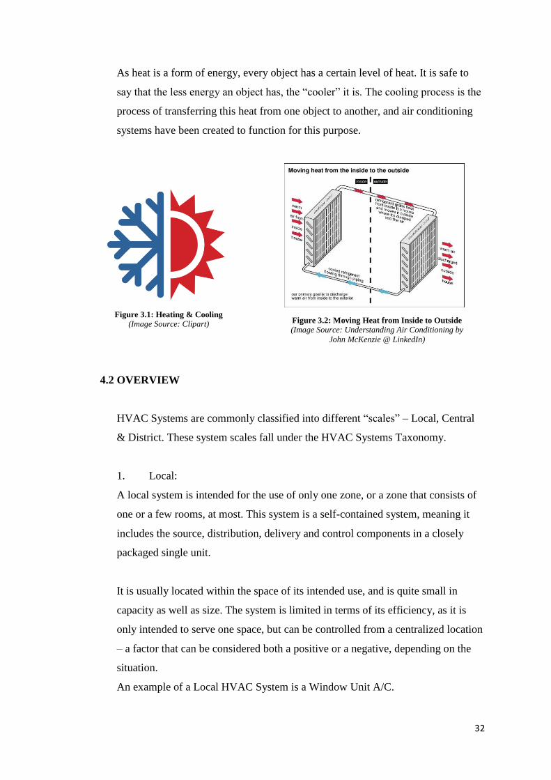
As heat is a form of energy, every object has a certain level of heat. It is safe to
say that the less energy an object has, the “cooler” it is. The cooling process is the
process of transferring this heat from one object to another, and air conditioning
systems have been created to function for this purpose.
4.2 OVERVIEW
HVAC Systems are commonly classified into different “scales” – Local, Central
& District. These system scales fall under the HVAC Systems Taxonomy.
1. Local:
A local system is intended for the use of only one zone, or a zone that consists of
one or a few rooms, at most. This system is a self-contained system, meaning it
includes the source, distribution, delivery and control components in a closely
packaged single unit.
It is usually located within the space of its intended use, and is quite small in
capacity as well as size. The system is limited in terms of its efficiency, as it is
only intended to serve one space, but can be controlled from a centralized location
– a factor that can be considered both a positive or a negative, depending on the
situation.
An example of a Local HVAC System is a Window Unit A/C.
Figure 3.1: Heating & Cooling
(Image Source: Clipart) Figure 3.2: Moving Heat from Inside to Outside
(Image Source: Understanding Air Conditioning by
John McKenzie @ LinkedIn)
33
2. Central:
A central system is meant to serve multiple zones from one location (or one
location, but from multiple zones). A distribution system is often required to
transport either heating or cooling from its place of origin (such as the mechanical
room) to the system of zones.
The system scope can vary from a single-family residence to an office or
laboratory, and a large-scaled building can be served by multiple or single central
systems in order to maximize efficiency.
An example of a Central HVAC System is a Variable Air Volume (VAV) system.
3. District:
A district system serves multiple buildings. It is normally used to provide both/or
either heating and cooling. The buildings they cater for usually have their own
central HVAC system, but economies of scale are possible with the large-capacity
equipment typical of a district system (this can include bulk purchase of fuels or
electricity, customized operating control sequences, etc.)
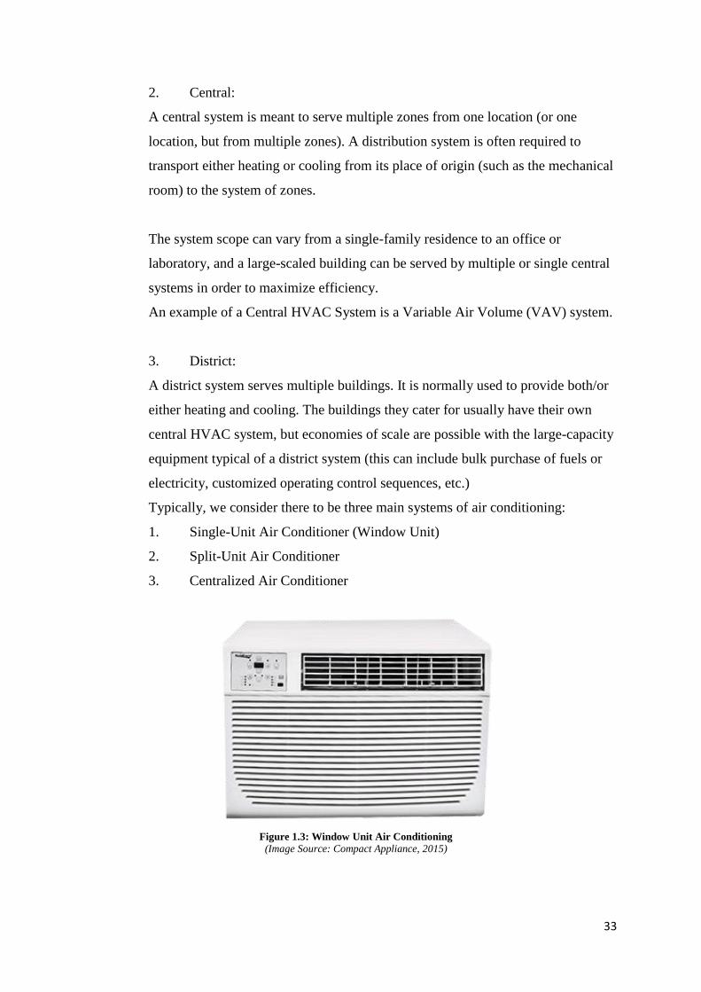
Typically, we consider there to be three main systems of air conditioning:
1. Single-Unit Air Conditioner (Window Unit)
2. Split-Unit Air Conditioner
3. Centralized Air Conditioner
Figure 1.3: Window Unit Air Conditioning (Image Source: Compact Appliance, 2015)
34
4.3 OPERATION OF SYSTEMS
4.3.1 DISTRIBUTION MEDIA
The distribution of heating and cooling is accomplished using either water,
or air, or water and air. As there are three different combinations, there are
three distinct classifications of the central HVAC system:
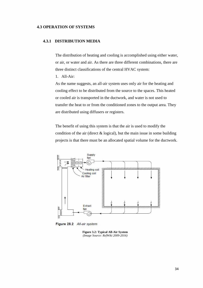
1. All-Air:
As the name suggests, an all-air system uses only air for the heating and
cooling effect to be distributed from the source to the spaces. This heated
or cooled air is transported in the ductwork, and water is not used to
transfer the heat to or from the conditioned zones to the output area. They
are distributed using diffusers or registers.
The benefit of using this system is that the air is used to modify the
condition of the air (direct & logical), but the main issue in some building
projects is that there must be an allocated spatial volume for the ductwork.
Figure 3.2: Typical All-Air System (Image Source: RefWiki 2009-2016)
35
2. Air-Water:
The air-water system uses a combination of both air and water. The bulk of
the heating and cooling effect is distributed from the source to the spaces
via hot or cold water, through pipes. Air is also supplied to the spaces from
a centralised unit, but typically with only enough air to ensure the indoor
air quality, though it can also be used to transfer a certain level of
heat/coolth.
The benefit of an air-water system is that there is a reduced demand for the
distribution volume (meaning the piping is smaller than an all-air system’s
ductwork) but with the same output of heating/cooling. The concern with
this system is that in some building projects, there is a concern of the
placement of the heat exchangers (delivery devices) within the occupied
space.
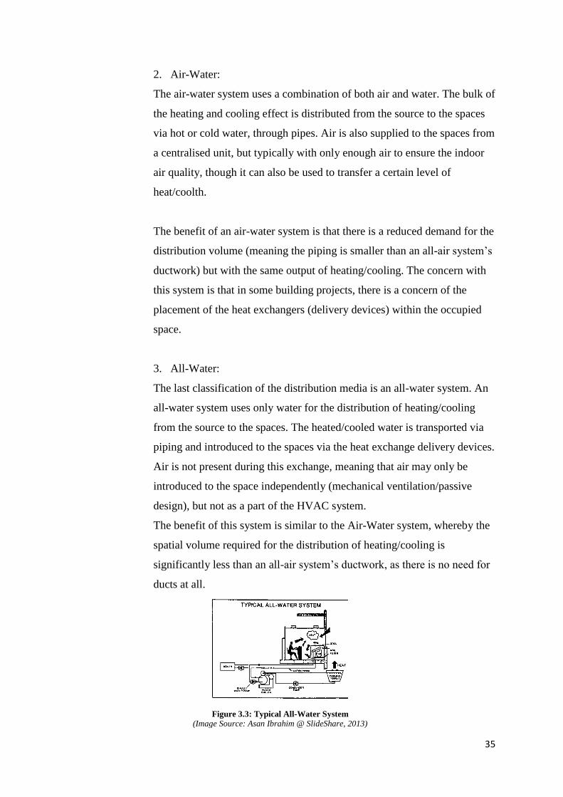
3. All-Water:
The last classification of the distribution media is an all-water system. An
all-water system uses only water for the distribution of heating/cooling
from the source to the spaces. The heated/cooled water is transported via
piping and introduced to the spaces via the heat exchange delivery devices.
Air is not present during this exchange, meaning that air may only be
introduced to the space independently (mechanical ventilation/passive
design), but not as a part of the HVAC system.
The benefit of this system is similar to the Air-Water system, whereby the
spatial volume required for the distribution of heating/cooling is
significantly less than an all-air system’s ductwork, as there is no need for
ducts at all.
Figure 3.3: Typical All-Water System (Image Source: Asan Ibrahim @ SlideShare, 2013)
36
4.4 PROPOSAL OF SYSTEM: SPLIT UNIT AIR CONDITIONING
4.4.1 INTRODUCTION OF SYSTEM
Split-Unit Air Conditioning system is one of the most widely used types of
air conditioners. It is used often in residential and moderately sized
buildings because of its efficiency, silent operation and elegant looks.
It is also a big upgrade from the single-unit window air conditioner as it
does not require the installation to be done by creation an unsightly hole in
the wall or mounting it on a window. This preserves the looks of the
building’s interior. Nowadays, there are many models for split unit air
conditioning, coming in a variety of colours, models and designs.
There are two parts of the split-unit air conditioner. There is an indoor
unit, as well as an outdoor unit. The indoor unit of the split air conditioner
is installed indoors, where the cooled air is supplied, while the outdoor unit
is installed outdoors, where the open space allows for the unit to be
installed and maintained easily.
This also allows for the silent operation as the condenser is used in the
outdoor unit. A copper tubing connects the two units together, and is an
integral component in the split-unit air conditioning.
4.4.2 APPLICATION TO OUR DESIGN
For our Building Services project, the most suitable HVAC system is a
Split-Unit Air Conditioning system, such as Daikin’s VRV Multi-Split
Unit System.
There are various reasons why it is considered the most suitable for this
design, as opposed to a centralised system:
• As the design of the building is done in a way whereby majority of the
spaces are outdoors, there are very few locations that actually require air
conditioning. In the entire structure, there are a total of only four rooms
that require mechanical cooling, therefore making a system like multi-split
unit system the most sensible and efficient choice.
37
• A multi-split unit air conditioning system takes up a lot less spatial
volume than a centralised system, as there are no ducts required. The space
required to run the distribution trees of the centralized system is
inappropriate for such a design.
• A variable refrigerant volume system is known for being a lot more
energy efficient.
• Using a multi-split unit system allows for multiple indoor units to be
groups with one outdoor unit – a fact that then allows it to be concealed
strategically from sight as there are few indoor units required.
• Split unit systems can come in various forms and designs, known for
being efficient and sleek as well as silent. This is suitable for a structure
catered to the elderly, where they may or may not be sensitive to noise and
obstructions. They can be either wall mounted or ceiling mounted
(cassette). The number, horse power (BTU) and positioning is dependent
on the size and space.
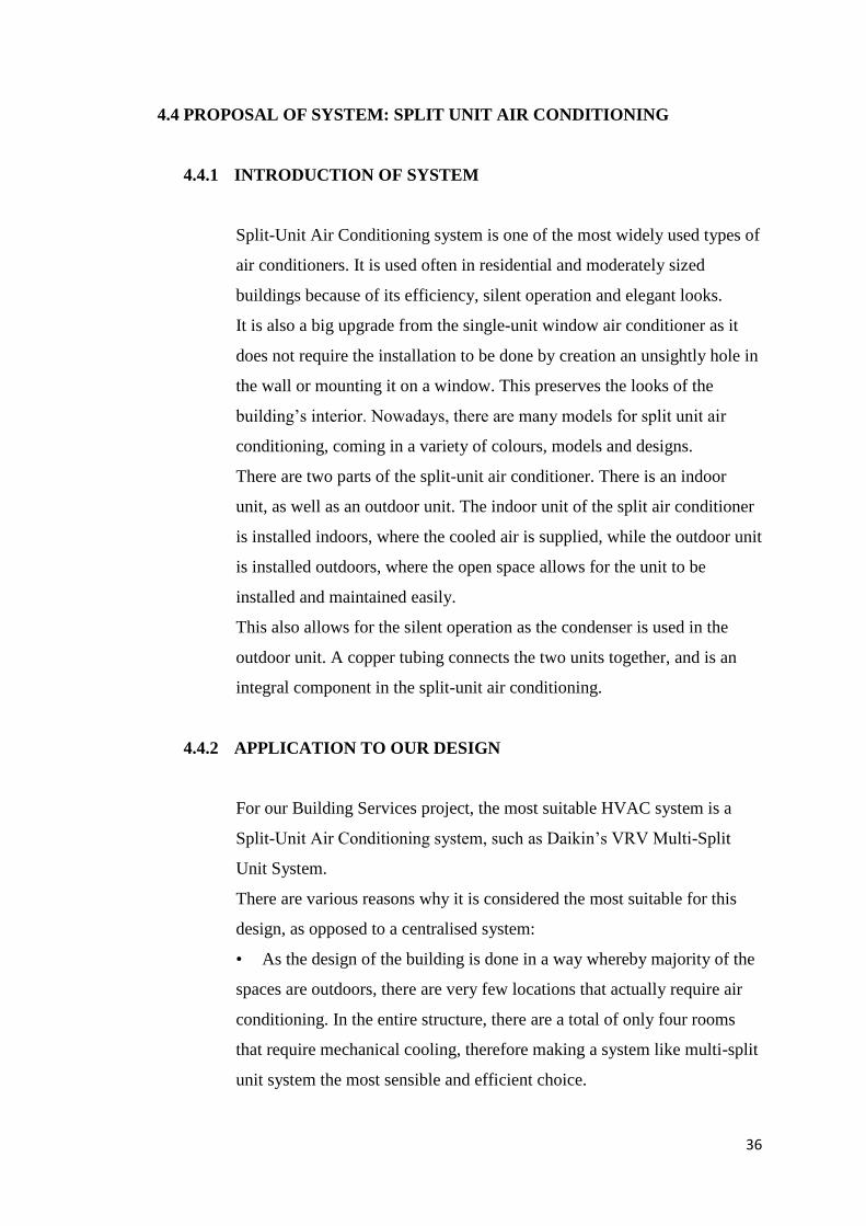
* Please refer to attached proper Plotted Drawings for HVAC Plans
The image above shows the location of the indoor and outdoor units of the
multi-split unit system on the first floor of the structure.
There are only two rooms on this floor that require air conditioning
(dimensions as stated in image).
Both units are wall-mounted indoor units, connected to the outdoor unit by
a red line (refrigerant pipe). As they are rooms that are both fairly close
Figure 3.4
38
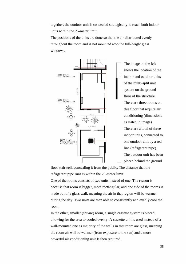
together, the outdoor unit is concealed strategically to reach both indoor
units within the 25-meter limit.
The positions of the units are done so that the air distributed evenly
throughout the room and is not mounted atop the full-height glass
windows.
The image on the left
shows the location of the
indoor and outdoor units
of the multi-split unit
system on the ground
floor of the structure.
There are three rooms on
this floor that require air
conditioning (dimensions
as stated in image).
There are a total of three
indoor units, connected to
one outdoor unit by a red
line (refrigerant pipe).
The outdoor unit has been
placed behind the ground
floor stairwell, concealing it from the public. The distance that the
refrigerant pipe runs is within the 25-meter limit.
One of the rooms consists of two units instead of one. The reason is
because that room is bigger, more rectangular, and one side of the rooms is
made out of a glass wall, meaning the air in that region will be warmer
during the day. Two units are then able to consistently and evenly cool the
room.
In the other, smaller (square) room, a single cassette system is placed,
allowing for the area to cooled evenly. A cassette unit is used instead of a
wall-mounted one as majority of the walls in that room are glass, meaning
the room air will be warmer (from exposure to the sun) and a more
powerful air conditioning unit Is then required.
39
4.4.3 PROCESS OF OPERATION
A split-unit air conditioning is widely used because of its silent operation.
It is also more favourable for small to moderately sized spaces because it
can be operated with a remote control instead of a control panel in a
separate location (eg. Centralised system)
The operation of a split unit system:
1. The Split-Unit air conditioner is controlled by an internal thermostat.
This thermostat is used to detect the indoor temperature of the space it
needs to cool. When it detects a difference between the desired
temperature and the space temperature, it will activate the other
components needed, such as the outdoor compressor.
2. When activated, this outdoor compressor begins to circulate a
refrigerant gas, and increases the pressure and temperature of this
refrigerant gas until it becomes a liquid.
3. As it compresses through a series of pipes, the refrigerant then moves
to the condenser.
4. In the condenser, the cooling system removes the heat from the high-
pressured gas, which changes into a cooled liquid.
5. This chilled liquid is then pushed through a tubing in the indoor unit
until it reaches the evaporation system.
6. Meanwhile, the air inside the room, which is warmer than the chilled
liquid, is collected from the room and into the indoor unit.
7. This warm room air is blown through a chamber containing the chilled
liquid refrigerant, where the heat exchange occurs, allowing the warm
room air to be chilled because of the chilled liquid refrigerant.
8. The chilled room air is now ready to be distributed back into the room
and cool the space. A fan system blows the cooled air back into the room,
lowering the overall temperature of the space.
9. The thermostat in the indoor unit continues to detect the air, and if the
room air is warmer than the desired/set temperature, the process is
repeated (steps 1-8), with the refrigerant, until the desired temperature is
obtained.
40
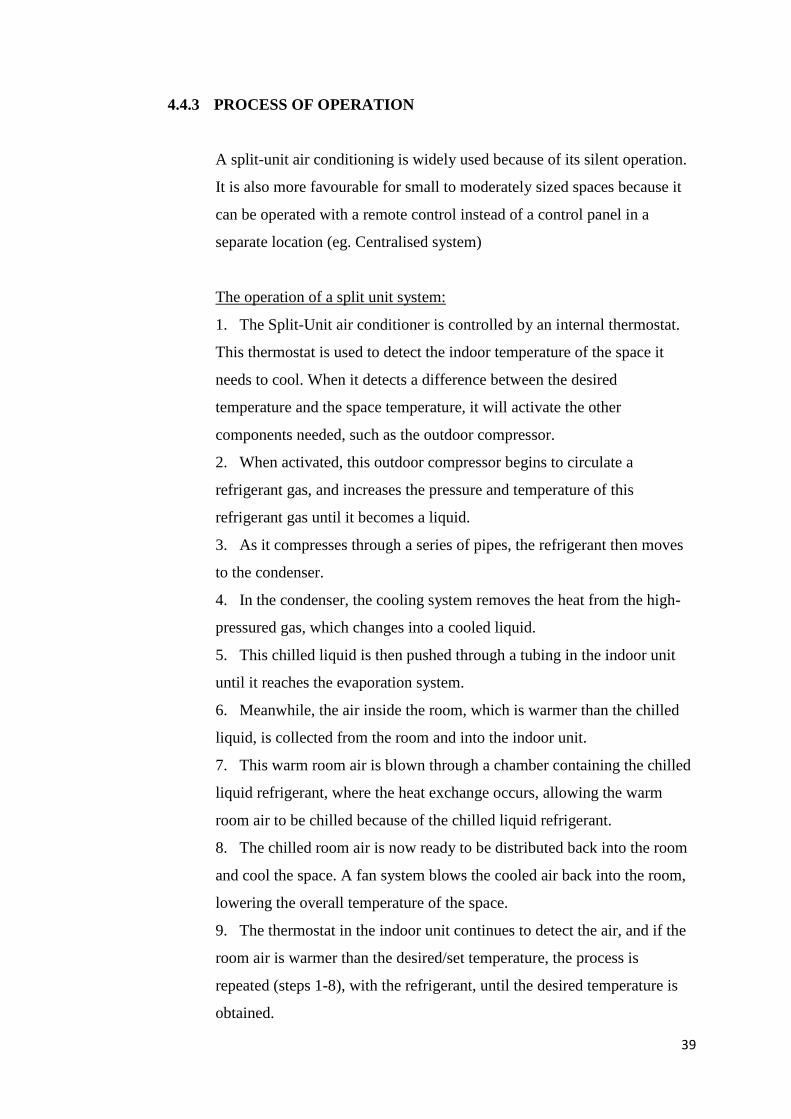
10. The excess heat that remains in the system is passed back outdoors to
the compressor in the outdoor unit in order to begin the cycle again.
Figure 3.4: Split-Unit A/C System (Image Source: Marshall B., Charles W.B. & Sara
E. @ HowStuffWorks.com, 2011)
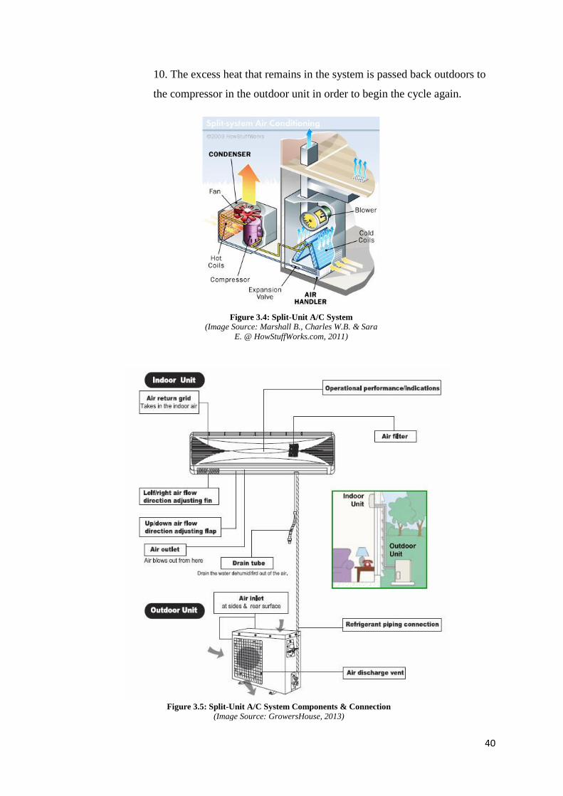
Figure 3.5: Split-Unit A/C System Components & Connection (Image Source: GrowersHouse, 2013)
41
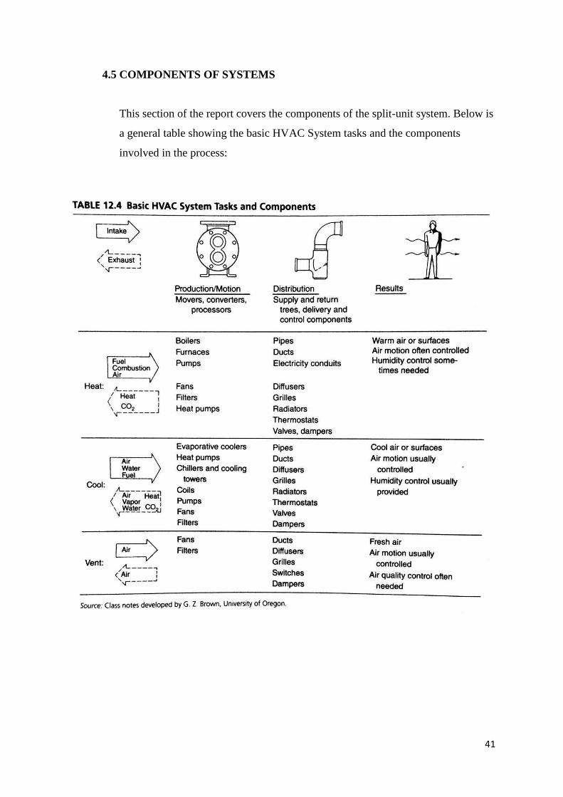
4.5 COMPONENTS OF SYSTEMS
This section of the report covers the components of the split-unit system. Below is
a general table showing the basic HVAC System tasks and the components
involved in the process:
42
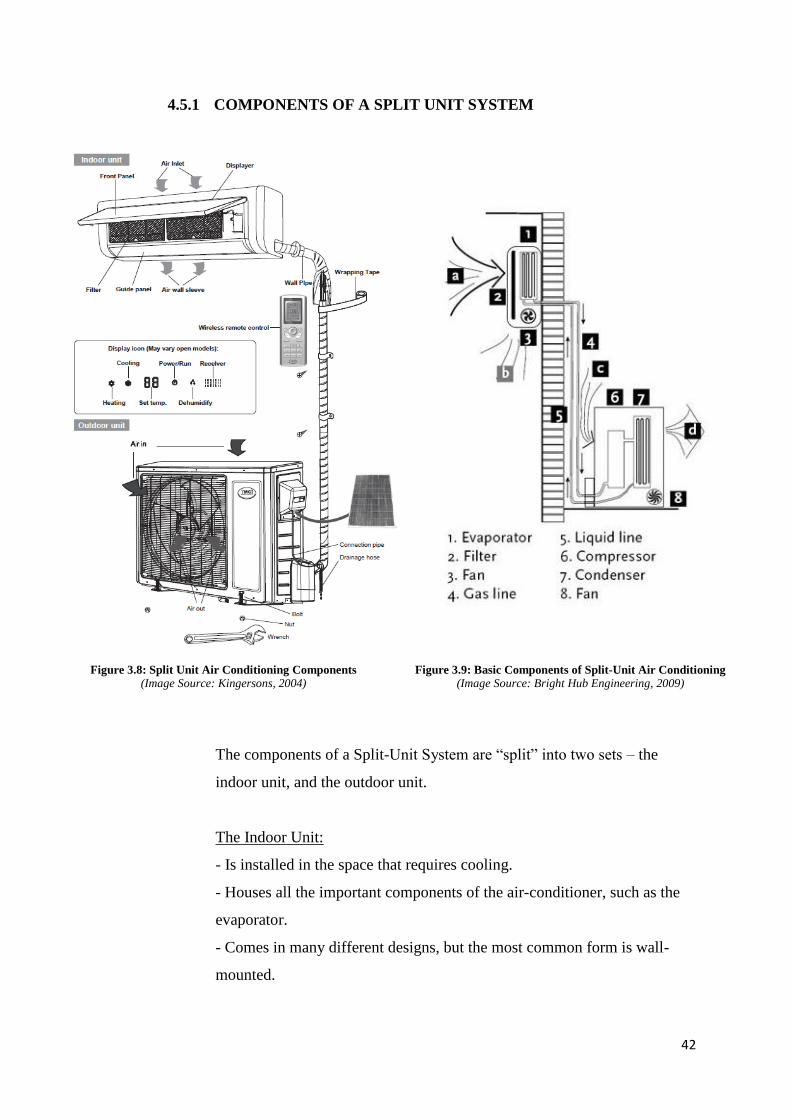
4.5.1 COMPONENTS OF A SPLIT UNIT SYSTEM
The components of a Split-Unit System are “split” into two sets – the
indoor unit, and the outdoor unit.
The Indoor Unit:
- Is installed in the space that requires cooling.
- Houses all the important components of the air-conditioner, such as the
evaporator.
- Comes in many different designs, but the most common form is wall-
mounted.
Figure 3.8: Split Unit Air Conditioning Components (Image Source: Kingersons, 2004)
Figure 3.9: Basic Components of Split-Unit Air Conditioning (Image Source: Bright Hub Engineering, 2009)
43
The Outdoor Unit:
- Is installed outdoors, near the indoor unit, allowing for the operation of
the indoor unit to be silent as the condenser and fan is located outside.
- Allows for easy maintenance & silent operation, as well as easy
installation.
- Has the general rule of being close to the indoor unit, as this allows for
the system to be more efficient.
Components for Indoor:
1. Evaporator/Cooling Coil
The evaporator or cooling coil is a copper coil turned multiple times. The
number of rows and turns in dependent of the capacity of the air
conditioning system. It is covered with aluminium, as this allows for the
heat transfer to be far more efficient.
It is responsible for cooling the atmospheric air that passes over it.
2. Air Filter
The air filter is – in ways – the most important part of the air conditioner.
It is responsible for filtering the atmospheric air that enters the indoor unit,
removing particles such as dirt, dust, lint and other harmful substances. By
removing the impurities, it cleans the air that is cooled, helping supply
clean, healthy, chilled air back into the room.
3. Cooling Fan/Blower
The cooling fan or blower is responsible for absorbing the air inside the
room, (atmospheric air). It is an induced type of blower that sucks the
room air, passing it over to the filter and the cooling coil, which allows for
the temperature change and filtration. It also supplies the cleaned air back
out into the space.
The shaft of the blower rotates inside the bushes and it is connected to a
speed motor, which allows for the user to adjust the speed of the blower.
44
4. Drain Pipe
The drain pipe collects the due that forms on the cooling coil when the
process of the heat exchange occurs. Due to the low temperature of the
cooling coil, the temperature is usually much below the dew point
temperature. When the room air passes over the cooling coil, the air
becomes very low, and dew forms. The water droplets are formed on the
surface of the cooling coil, which will build up until it drops. When this
happens, the drain pipe is responsible for safely leading the collection of
the water to the external space.
5. Louvers/Fins
The louvres or fins of the air conditioner helps changes the angle or the
direction in which the air needs to be supplied back into the room. With
one change, the direction of the cooled air can be adjusted.
There are two types of louvres, horizontal and vertical. They can be
changed with the help of the remote control, allowing it to be in a fixed
position, or in a rotational mode, which automatically moves.
The Components for Outdoor
1. Compressor
The compressor is the most important part of any air conditioner, because
it is responsible for compressing the refrigerant and increasing the pressure
before sending it to the condenser. The size depends on the loading.
The compressor has a motor used for driving the shaft that is located inside
a sealed unit. This unit is not visible externally, but requires external
power for compressing the refrigerant.
2. Condenser
The condenser in the outdoor unit is a coiled copper tubing, with rows and
turns that is dependent on the capacity and size of the air conditioner unit
and compressor. The greater tonnage the air conditioner has, te more turns
and rows the condenser has.
The high temperature and high pressure of the refrigerant from the
compressor comes in the condenser, where it has to forfeit the heat. The
45
tubing is therefore made up of copper since the rate of conducting heat in
copper is high. It is also covered in aluminium fins so that the heat is
removed at a faster rate.
3. Cooling Fan
The cooling fan is driven by a motor, and located in the front of the
compressor and condenser coil. It is responsible for removing the heat of
the compressor, otherwise it will get too hot in the long run, and the motor
coil will burn.
It is usually located in the front of the compressor and the condenser coil,
made out of three or four blades that is driven by a motor. It absorbs the
outdoor air and blows it over the compressor and condenser, cooling it.
The hot air is thrown back out into the open space after cooling the
compressor and condenser. This is why standing in front of the outdoor
unit is usually warm.
4. Expansion Valve
The expansion valve is usually a copper capillary tubing, which also has a
number of coils. The high pressure and temperature refrigerant enters the
expansion valve, where it is reduced suddenly.
4.6 UBBL REGULATIONS (CONCERNING HVAC)
8.1.2 Indoor design conditions
Recommended:
Design dry bulb temperature 23 ºC – 26 °C
Minimum dry bulb temperature 22 °C
Design relative humidity 55 % – 70 %
Air movement 0.15 – 0.50 m/s
Maximum air movement 0.7 m/s
46
8.2 System and equipment sizing:
Air conditioning systems and equipment shall be sized to provide no more than
the space and system loads calculated, consistent with available equipment
capacity.
Redundancy in capacity of equipment, if incorporated into the sizing of the duty
equipment, shall include efficiency devices such as variable speed drive, high
efficiency motor, efficient unloading devices, multi compressors, etc. so as not to
diminish the equipment/system efficiency when operating at varying loads.
8.2 System and equipment sizing
Where chillers are used and when the design load is greater than 1000 kWr, a
minimum of either two chillers or a single multi-compressor chiller should be
provided to meet the required load.
Multiple units of the same equipment type, such as multiple chillers, with
combined capacities exceeding the design load may be specified to operate
concurrently only if controls are provided which sequence or otherwise optimally
control the operation of each unit based on the required cooling load.
8.4 Controls Temperature control
Each system shall be provided with at least one thermostat for the regulation of
temperature. Each thermostat shall be capable of being set by adjustment or
selection of sensors over a minimum range of between 22 °C to 27 °C. Multi-stage
thermostat shall be provided for equipment exceeding 35/65 kWr in conjunction
with 8.2.4.
8.4 Controls
Energy Recovery
It is recommended that consideration be given to the use of recovery systems
which will conserve energy (provided the amount expended is less than the
amount recovered) when the energy transfer potential and the operating hours are
considered.
47
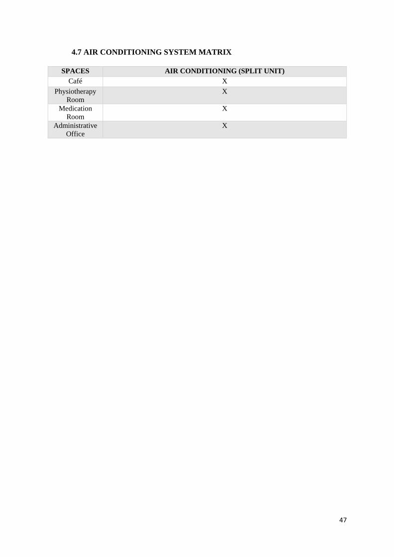
4.7 AIR CONDITIONING SYSTEM MATRIX
SPACES AIR CONDITIONING (SPLIT UNIT)
Café X
Physiotherapy
Room
X
Medication
Room
X
Administrative
Office
X
48
5. MECHANICAL (AND NATURAL) VENTILATION SYSTEM
(Prepared by: Philia Chua Yi Sian and Ricco Soh Zheng Wei)
5.1 LITERATURE REVIEW
Mechanical ventilation is the process by which stale air is exchanged with fresh
air in an enclosed space to provide a better indoor air quality for the building.
To achieve this, the usage of mechanical ventilation is required to ensure that the
building is well ventilated with fresh air while stale air such as indoor pollutants,
carbon dioxide, moisture and odor are expel from the building. Besides ensuring a
better indoor air quality for the building, the other advantage of mechanical
ventilation is to have more control over the intake and outtake of fresh air in an
appropriate locations and improving comfort for the user of the building through
filtration, dehumidification and also conditioning of incoming air.
The importance of mechanical ventilation would be able to preserve oxygen and
removal of carbon dioxide, control of humidity for human comfort, prevention of
heat concentrations from machinery, lighting and people, dispersal of
concentrations of bacteria, dilution and disposal of contaminants such as smoke
gas, dust and body odors, provision of freshness and lastly, an alternative to the
unreliable natural system.
There are few types of ventilation system which would be:
-Extract-only ventilation system
-Supply and extract ventilation system
-Balance ventilation system
These system are achieved with spot ventilation which includes the use of
localized exhaust fans and is mainly recommended in all enclosed areas such as
kitchen and bathroom spots. Ventilation fans are intended to reduce
concentrations of unwanted pollutants air in the living space. Exhaust fans should
be placed close to one another to extract source of moisture or unwanted
pollutants.
49
5.2 OVERVIEW
Mechanical (or ‘forced’) ventilation tends to be driven by fans. This system is
mainly used for applications where natural ventilation is not appropriate.
Natural ventilation on the other hand, is driven by ‘natural’ pressure differences
from one part of the building to another.
Mechanical systems are necessary when:
1. The building is too deep to ventilate from the perimeter.
2. Local air quality is poor, for example if a building is next to a busy road.
3. Local noise levels mean that windows cannot be opened.
4. The local urban structure is very dense and shelters the building from the wind.
5. Privacy or security requirements prevent windows from being opened.
6. Internal partitions block air paths.
7. The density of occupation, equipment, lighting and so on creates very high heat
loads or high levels of contaminants.
5.3 INTRODUCTION OF PROPOSED SYSTEMS
5.3.1 EXTRACT-ONLY SYSTEM (MECHANICAL VENTILATION)
Fan-assisted extract system works by enhancing the air movement to
exhaust latent heat when the internal temperature is high. Mechanical
ventilation systems can have both supplier and extract vents assisted by
fans (The Greenage, 2016), however, only extract vents are needed for this
building at the kitchen and toilet areas, as the spaces are mostly open-aired
and sufficient air flow is provided. These systems may also include filters
to ensure a higher standard of indoor air quality, coupled with heating and/
or cooling coils.
The function of the exhaust-only system is to extract stale and humid air
from the kitchen, bathroom and toilet ("Types of ventilation", 2016)
50
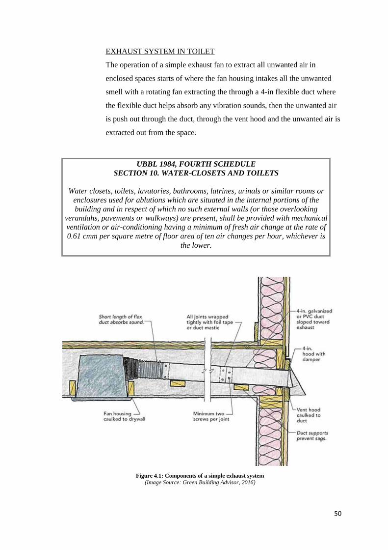
EXHAUST SYSTEM IN TOILET
The operation of a simple exhaust fan to extract all unwanted air in
enclosed spaces starts of where the fan housing intakes all the unwanted
smell with a rotating fan extracting the through a 4-in flexible duct where
the flexible duct helps absorb any vibration sounds, then the unwanted air
is push out through the duct, through the vent hood and the unwanted air is
extracted out from the space.
UBBL 1984, FOURTH SCHEDULE
SECTION 10. WATER-CLOSETS AND TOILETS
Water closets, toilets, lavatories, bathrooms, latrines, urinals or similar rooms or
enclosures used for ablutions which are situated in the internal portions of the
building and in respect of which no such external walls (or those overlooking
verandahs, pavements or walkways) are present, shall be provided with mechanical
ventilation or air-conditioning having a minimum of fresh air change at the rate of
0.61 cmm per square metre of floor area of ten air changes per hour, whichever is
the lower.
Figure 4.1: Components of a simple exhaust system (Image Source: Green Building Advisor, 2016)
51
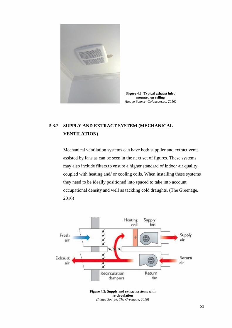
5.3.2 SUPPLY AND EXTRACT SYSTEM (MECHANICAL
VENTILATION)
Mechanical ventilation systems can have both supplier and extract vents
assisted by fans as can be seen in the next set of figures. These systems
may also include filters to ensure a higher standard of indoor air quality,
coupled with heating and/ or cooling coils. When installing these systems
they need to be ideally positioned into spaced to take into account
occupational density and well as tackling cold draughts. (The Greenage,
2016)
Figure 4.2: Typical exhaust inlet
mounted on ceiling (Image Source: Colourdot.co, 2016)
Figure 4.3: Supply and extract systems with
re-circulation (Image Source: The Greenage, 2016)
52
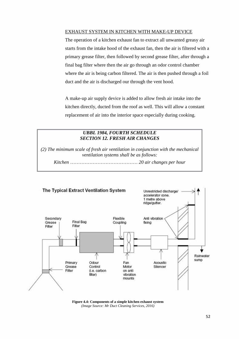
EXHAUST SYSTEM IN KITCHEN WITH MAKE-UP DEVICE
The operation of a kitchen exhaust fan to extract all unwanted greasy air
starts from the intake hood of the exhaust fan, then the air is filtered with a
primary grease filter, then followed by second grease filter, after through a
final bag filter where then the air go through an odor control chamber
where the air is being carbon filtered. The air is then pushed through a foil
duct and the air is discharged our through the vent hood.
A make-up air supply device is added to allow fresh air intake into the
kitchen directly, ducted from the roof as well. This will allow a constant
replacement of air into the interior space especially during cooking.
UBBL 1984, FOURTH SCHEDULE
SECTION 12. FRESH AIR CHANGES
(2) The minimum scale of fresh air ventilation in conjunction with the mechanical
ventilation systems shall be as follows:
Kitchen …………………………………… 20 air changes per hour
Figure 4.4: Components of a simple kitchen exhaust system (Image Source: Mr Duct Cleaning Services, 2016)
53
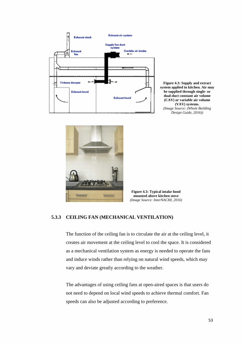
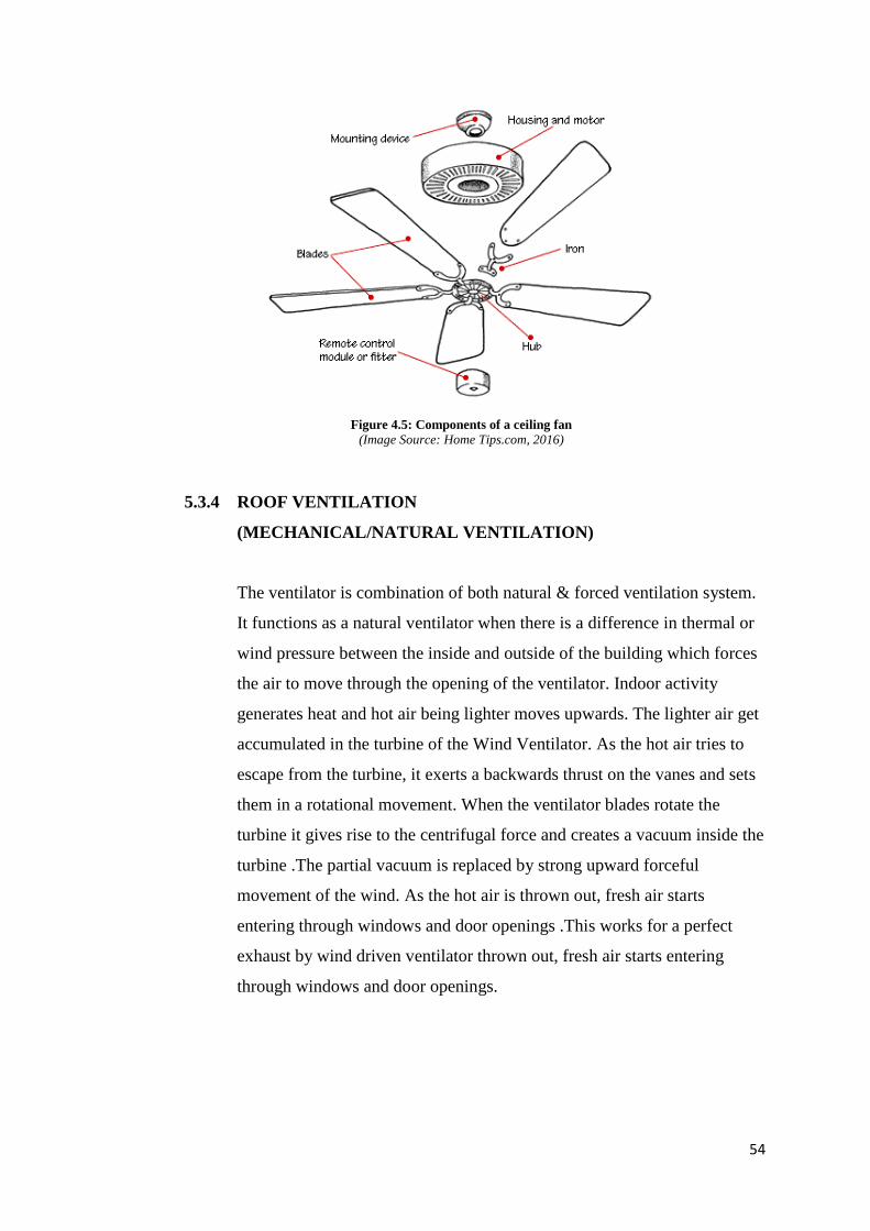
5.3.3 CEILING FAN (MECHANICAL VENTILATION)
The function of the ceiling fan is to circulate the air at the ceiling level, it
creates air movement at the ceiling level to cool the space. It is considered
as a mechanical ventilation system as energy is needed to operate the fans
and induce winds rather than relying on natural wind speeds, which may
vary and deviate greatly according to the weather.
The advantages of using ceiling fans at open-aired spaces is that users do
not need to depend on local wind speeds to achieve thermal comfort. Fan
speeds can also be adjusted according to preference.
Figure 4.3: Typical intake hood
mounted above kitchen stove (Image Source: InterNACHI, 2016)
Figure 4.3: Supply and extract
system applied in kitchen. Air may
be supplied through single- or
dual-duct constant air volume
(CAV) or variable air volume
(VAV) systems. (Image Source: (Whole Building
Design Guide, 2016))
54
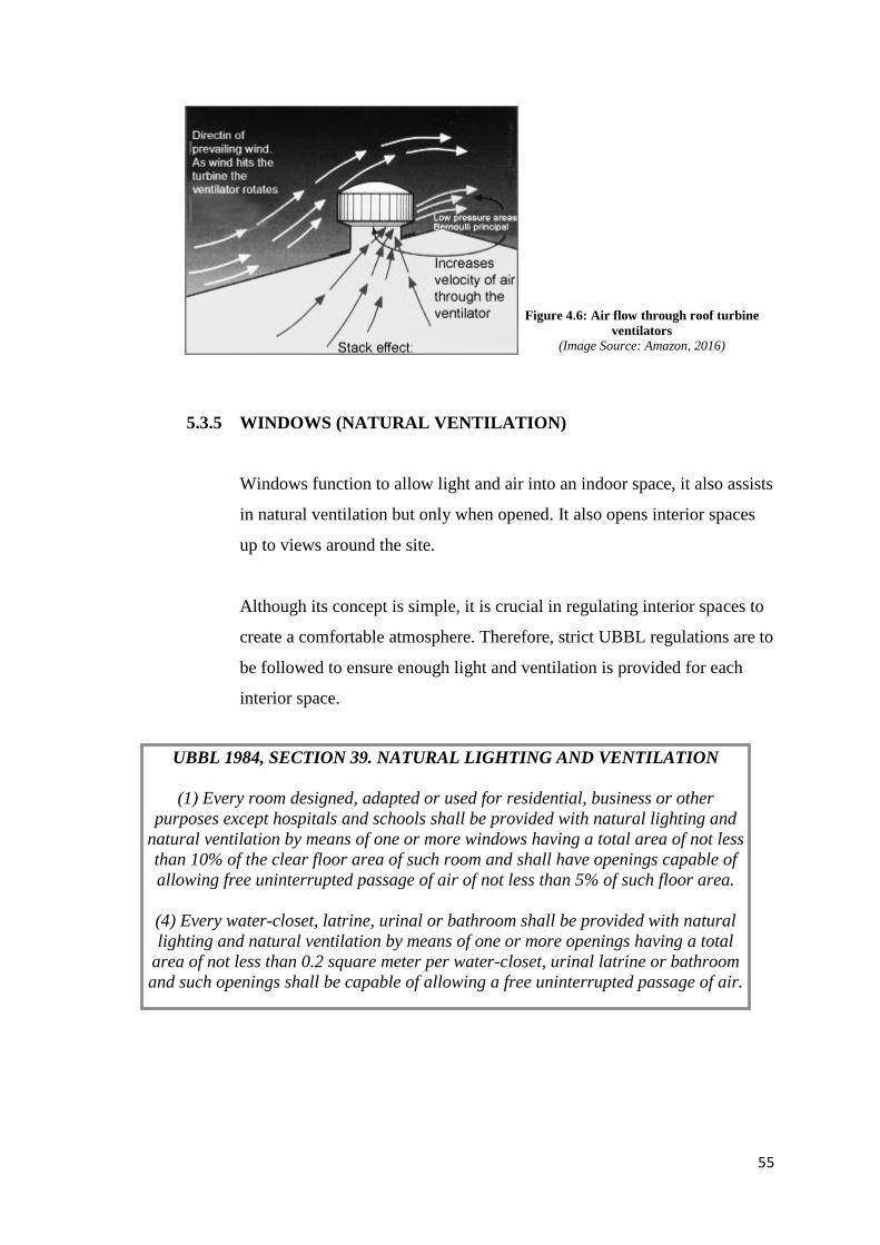
5.3.4 ROOF VENTILATION
(MECHANICAL/NATURAL VENTILATION)
The ventilator is combination of both natural & forced ventilation system.
It functions as a natural ventilator when there is a difference in thermal or
wind pressure between the inside and outside of the building which forces
the air to move through the opening of the ventilator. Indoor activity
generates heat and hot air being lighter moves upwards. The lighter air get
accumulated in the turbine of the Wind Ventilator. As the hot air tries to
escape from the turbine, it exerts a backwards thrust on the vanes and sets
them in a rotational movement. When the ventilator blades rotate the
turbine it gives rise to the centrifugal force and creates a vacuum inside the
turbine .The partial vacuum is replaced by strong upward forceful
movement of the wind. As the hot air is thrown out, fresh air starts
entering through windows and door openings .This works for a perfect
exhaust by wind driven ventilator thrown out, fresh air starts entering
through windows and door openings.
Figure 4.5: Components of a ceiling fan (Image Source: Home Tips.com, 2016)
55
5.3.5 WINDOWS (NATURAL VENTILATION)
Windows function to allow light and air into an indoor space, it also assists
in natural ventilation but only when opened. It also opens interior spaces
up to views around the site.
Although its concept is simple, it is crucial in regulating interior spaces to
create a comfortable atmosphere. Therefore, strict UBBL regulations are to
be followed to ensure enough light and ventilation is provided for each
interior space.
Figure 4.6: Air flow through roof turbine
ventilators (Image Source: Amazon, 2016)
UBBL 1984, SECTION 39. NATURAL LIGHTING AND VENTILATION
(1) Every room designed, adapted or used for residential, business or other
purposes except hospitals and schools shall be provided with natural lighting and
natural ventilation by means of one or more windows having a total area of not less
than 10% of the clear floor area of such room and shall have openings capable of
allowing free uninterrupted passage of air of not less than 5% of such floor area.
(4) Every water-closet, latrine, urinal or bathroom shall be provided with natural
lighting and natural ventilation by means of one or more openings having a total
area of not less than 0.2 square meter per water-closet, urinal latrine or bathroom
and such openings shall be capable of allowing a free uninterrupted passage of air.
56
5.4 APPLICATION OF PROPOSED SYSTEMS INTO BUILDING
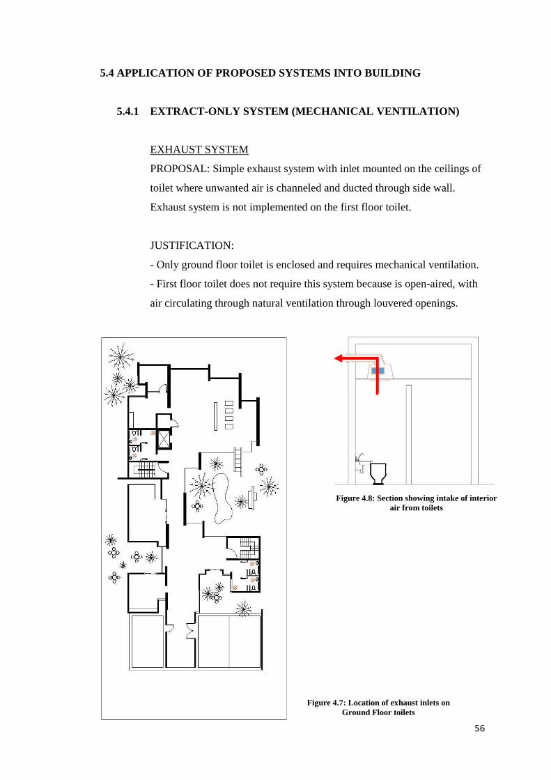
5.4.1 EXTRACT-ONLY SYSTEM (MECHANICAL VENTILATION)
EXHAUST SYSTEM
PROPOSAL: Simple exhaust system with inlet mounted on the ceilings of
toilet where unwanted air is channeled and ducted through side wall.
Exhaust system is not implemented on the first floor toilet.
JUSTIFICATION:
- Only ground floor toilet is enclosed and requires mechanical ventilation.
- First floor toilet does not require this system because is open-aired, with
air circulating through natural ventilation through louvered openings.
Figure 4.8: Section showing intake of interior
air from toilets
Figure 4.7: Location of exhaust inlets on
Ground Floor toilets
57
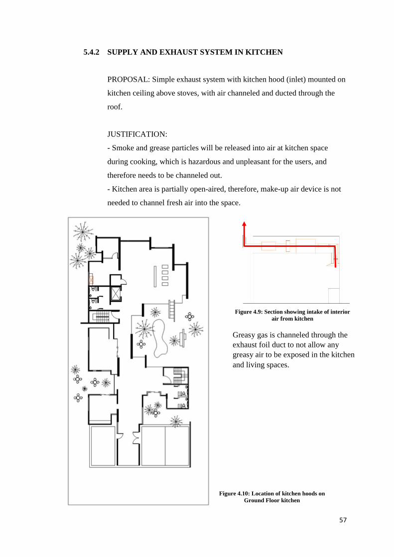
5.4.2 SUPPLY AND EXHAUST SYSTEM IN KITCHEN
PROPOSAL: Simple exhaust system with kitchen hood (inlet) mounted on
kitchen ceiling above stoves, with air channeled and ducted through the
roof.
JUSTIFICATION:
- Smoke and grease particles will be released into air at kitchen space
during cooking, which is hazardous and unpleasant for the users, and
therefore needs to be channeled out.
- Kitchen area is partially open-aired, therefore, make-up air device is not
needed to channel fresh air into the space.
Figure 4.10: Location of kitchen hoods on
Ground Floor kitchen
Greasy gas is channeled through the
exhaust foil duct to not allow any
greasy air to be exposed in the kitchen
and living spaces.
Figure 4.9: Section showing intake of interior
air from kitchen
58
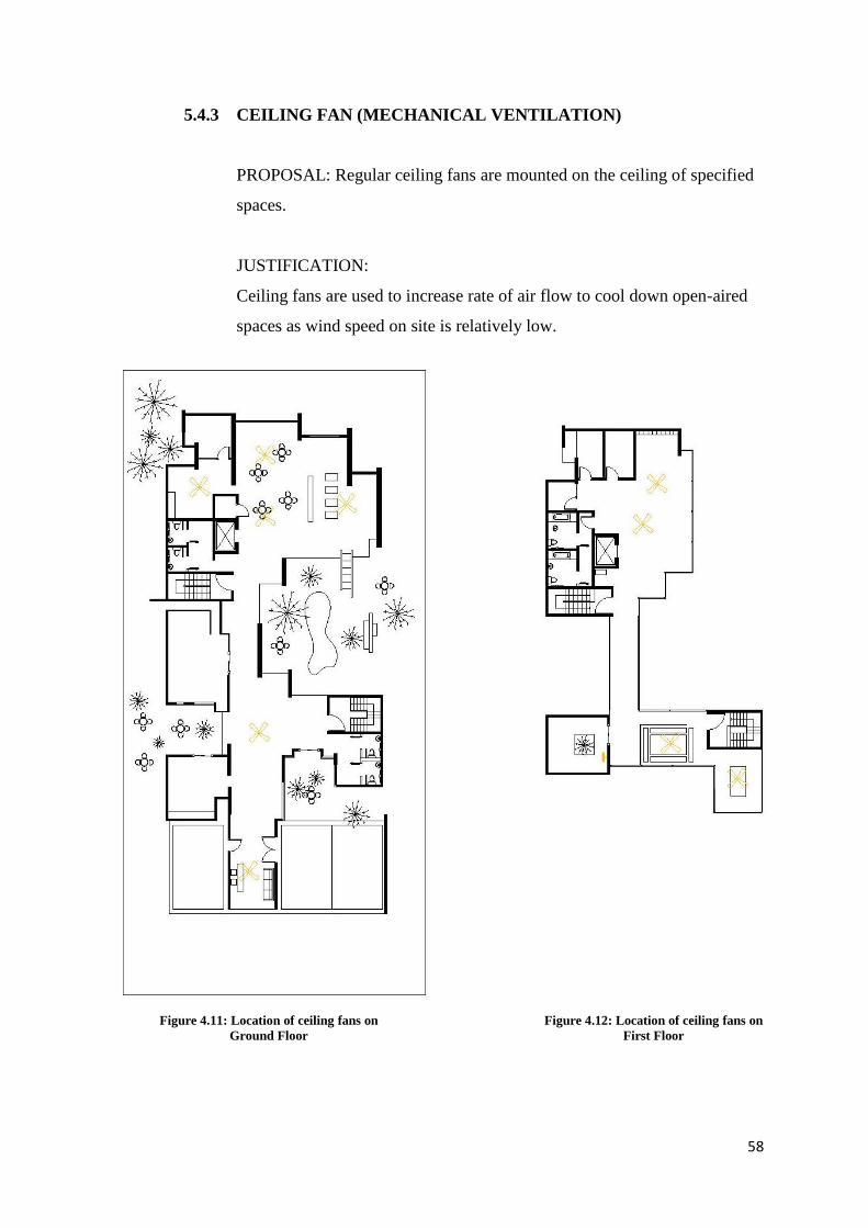
5.4.3 CEILING FAN (MECHANICAL VENTILATION)
PROPOSAL: Regular ceiling fans are mounted on the ceiling of specified
spaces.
JUSTIFICATION:
Ceiling fans are used to increase rate of air flow to cool down open-aired
spaces as wind speed on site is relatively low.
Figure 4.11: Location of ceiling fans on
Ground Floor
Figure 4.12: Location of ceiling fans on
First Floor
59
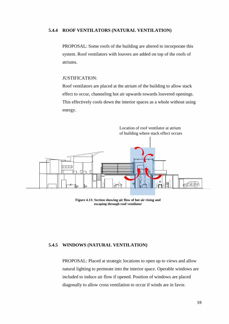
5.4.4 ROOF VENTILATORS (NATURAL VENTILATION)
PROPOSAL: Some roofs of the building are altered to incorporate this
system. Roof ventilators with louvers are added on top of the roofs of
atriums.
JUSTIFICATION:
Roof ventilators are placed at the atrium of the building to allow stack
effect to occur, channeling hot air upwards towards louvered openings.
This effectively cools down the interior spaces as a whole without using
energy.
5.4.5 WINDOWS (NATURAL VENTILATION)
PROPOSAL: Placed at strategic locations to open up to views and allow
natural lighting to permeate into the interior space. Operable windows are
included to induce air flow if opened. Position of windows are placed
diagonally to allow cross ventilation to occur if winds are in favor.
Location of roof ventilator at atrium
of building where stack effect occurs
Figure 4.13: Section showing air flow of hot air rising and
escaping through roof ventilator
60
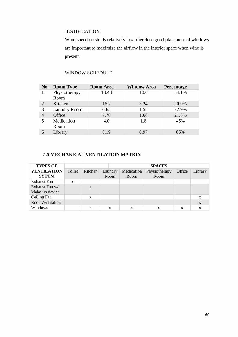
JUSTIFICATION:
Wind speed on site is relatively low, therefore good placement of windows
are important to maximize the airflow in the interior space when wind is
present.
WINDOW SCHEDULE
5.5 MECHANICAL VENTILATION MATRIX
TYPES OF
VENTILATION
SYTEM
SPACES
Toilet Kitchen Laundry
Room
Medication
Room
Physiotherapy
Room
Office Library
Exhaust Fan x
Exhaust Fan w/
Make-up device
x
Ceiling Fan x x
Roof Ventilation x
Windows x x x x x x
No. Room Type Room Area Window Area Percentage
1 Physiotherapy
Room
18.48 10.0 54.1%
2 Kitchen 16.2 3.24 20.0%
3 Laundry Room 6.65 1.52 22.9%
4 Office 7.70 1.68 21.8%
5 Medication
Room
4.0 1.8 45%
6 Library 8.19 6.97 85%
61
6. MECHANICAL TRANSPORTATION SYSTEM (Prepared by: Tang Wei Xin)
6.1 LITERATURE REVIEW
Recent years, buildings are built vertically due to the rapid development and high
land cost. The importance of mechanical transportation within a building was then
emphasized. Not only to assist in moving goods or people, but also helped to
transport the disabled and inconvenient. Indeed, the mechanical transportation
enhances the quality of life by providing the convenience and reduces the fatigue.
However, every mechanical transportation should abide by the UBBL as well as
fire requirements to provide basic and safety needs. For considerations, it should
provide minimum waiting time, comfortable acceleration, smooth braking system
and rapid transportation for better services.
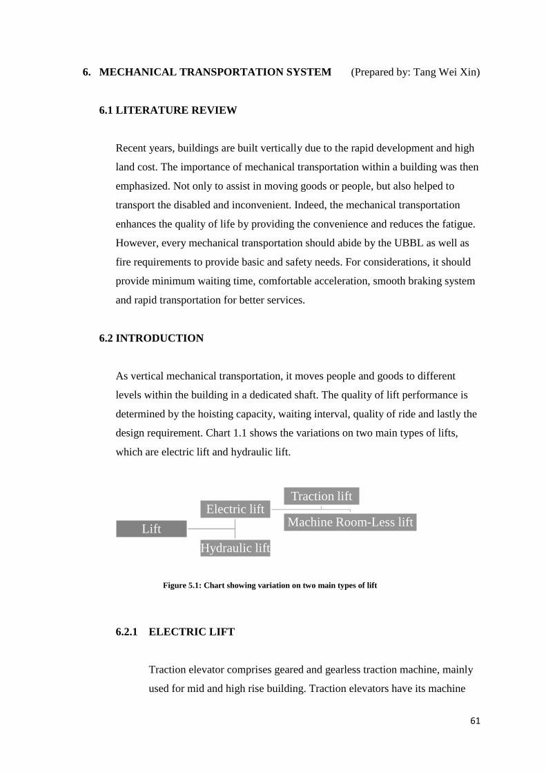
6.2 INTRODUCTION
As vertical mechanical transportation, it moves people and goods to different
levels within the building in a dedicated shaft. The quality of lift performance is
determined by the hoisting capacity, waiting interval, quality of ride and lastly the
design requirement. Chart 1.1 shows the variations on two main types of lifts,
which are electric lift and hydraulic lift.
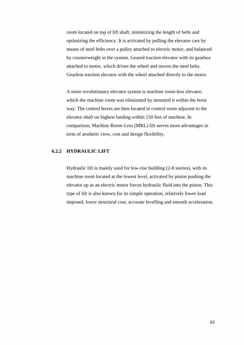
6.2.1 ELECTRIC LIFT
Traction elevator comprises geared and gearless traction machine, mainly
used for mid and high rise building. Traction elevators have its machine
Lift
Electric liftTraction lift
Machine Room-Less lift
Hydraulic lift
Figure 5.1: Chart showing variation on two main types of lift
62
room located on top of lift shaft, minimizing the length of belts and
optimizing the efficiency. It is activated by pulling the elevator cars by
means of steel belts over a pulley attached to electric motor, and balanced
by counterweight in the system. Geared traction elevator with its gearbox
attached to motor, which drives the wheel and moves the steel belts.
Gearless traction elevator with the wheel attached directly to the motor.
A more revolutionary elevator system is machine room-less elevator,
which the machine room was eliminated by mounted it within the hoist
way. The control boxes are then located in control room adjacent to the
elevator shaft on highest landing within 150 feet of machine. In
comparison, Machine Room-Less (MRL) lift serves more advantages in
term of aesthetic view, cost and design flexibility.
6.2.2 HYDRAULIC LIFT
Hydraulic lift is mainly used for low-rise building (2-8 stories), with its
machine room located at the lowest level, activated by piston pushing the
elevator up as an electric motor forces hydraulic fluid into the piston. This
type of lift is also known for its simple operation, relatively lower load
imposed, lower structural cost, accurate levelling and smooth acceleration.
63
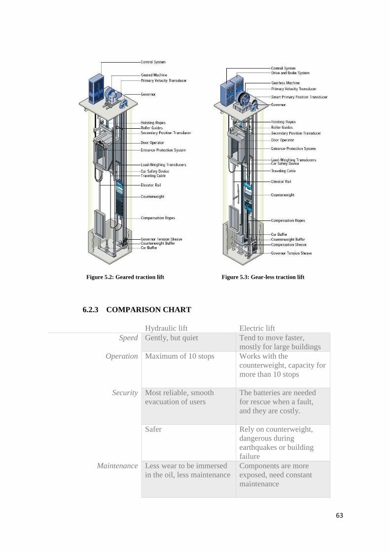
6.2.3 COMPARISON CHART
Hydraulic lift Electric lift
Speed Gently, but quiet Tend to move faster,
mostly for large buildings
Operation Maximum of 10 stops Works with the
counterweight, capacity for
more than 10 stops
Security Most reliable, smooth
evacuation of users
The batteries are needed
for rescue when a fault,
and they are costly.
Safer Rely on counterweight,
dangerous during
earthquakes or building
failure
Maintenance Less wear to be immersed
in the oil, less maintenance
Components are more
exposed, need constant
maintenance
Figure 5.2: Geared traction lift Figure 5.3: Gear-less traction lift
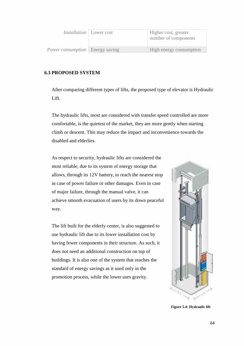
64
Installation Lower cost Higher cost, greater
number of components
Power consumption Energy saving High energy consumption
6.3 PROPOSED SYSTEM
After comparing different types of lifts, the proposed type of elevator is Hydraulic
Lift.
The hydraulic lifts, most are considered with transfer speed controlled are more
comfortable, is the quietest of the market, they are more gently when starting
climb or descent. This may reduce the impact and inconvenience towards the
disabled and elderlies.
As respect to security, hydraulic lifts are considered the
most reliable, due to its system of energy storage that
allows, through its 12V battery, to reach the nearest stop
in case of power failure or other damages. Even in case
of major failure, through the manual valve, it can
achieve smooth evacuation of users by its down peaceful
way.
The lift built for the elderly center, is also suggested to
use hydraulic lift due to its lower installation cost by
having fewer components in their structure. As such, it
does not need an additional construction on top of
buildings. It is also one of the system that reaches the
standard of energy savings as it used only in the
promotion process, while the lower uses gravity.
Figure 5.4: Hydraulic lift
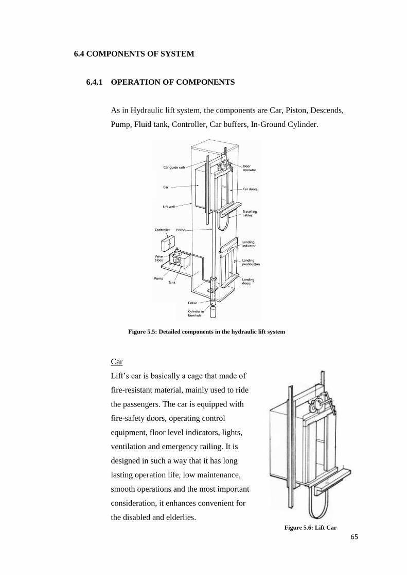
65
6.4 COMPONENTS OF SYSTEM
6.4.1 OPERATION OF COMPONENTS
As in Hydraulic lift system, the components are Car, Piston, Descends,
Pump, Fluid tank, Controller, Car buffers, In-Ground Cylinder.
Car
Lift’s car is basically a cage that made of
fire-resistant material, mainly used to ride
the passengers. The car is equipped with
fire-safety doors, operating control
equipment, floor level indicators, lights,
ventilation and emergency railing. It is
designed in such a way that it has long
lasting operation life, low maintenance,
smooth operations and the most important
consideration, it enhances convenient for
the disabled and elderlies.
Figure 5.5: Detailed components in the hydraulic lift system
Figure 5.6: Lift Car
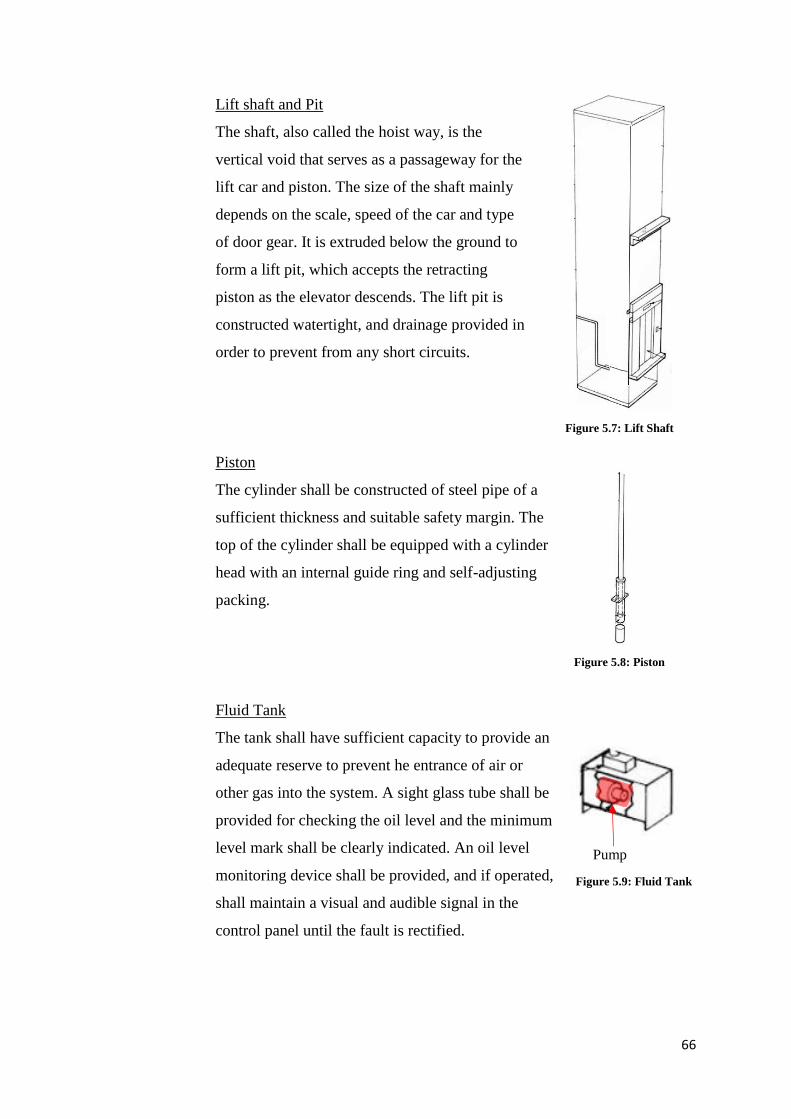
66
Lift shaft and Pit
The shaft, also called the hoist way, is the
vertical void that serves as a passageway for the
lift car and piston. The size of the shaft mainly
depends on the scale, speed of the car and type
of door gear. It is extruded below the ground to
form a lift pit, which accepts the retracting
piston as the elevator descends. The lift pit is
constructed watertight, and drainage provided in
order to prevent from any short circuits.
Piston
The cylinder shall be constructed of steel pipe of a
sufficient thickness and suitable safety margin. The
top of the cylinder shall be equipped with a cylinder
head with an internal guide ring and self-adjusting
packing.
Fluid Tank
The tank shall have sufficient capacity to provide an
adequate reserve to prevent he entrance of air or
other gas into the system. A sight glass tube shall be
provided for checking the oil level and the minimum
level mark shall be clearly indicated. An oil level
monitoring device shall be provided, and if operated,
shall maintain a visual and audible signal in the
control panel until the fault is rectified.
Figure 5.7: Lift Shaft
Figure 5.8: Piston
Pump
Figure 5.9: Fluid Tank
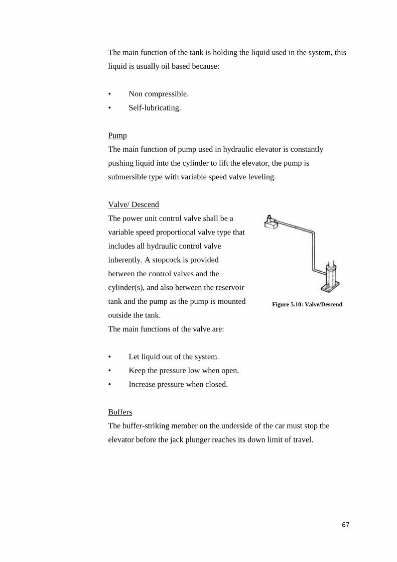
67
The main function of the tank is holding the liquid used in the system, this
liquid is usually oil based because:
• Non compressible.
• Self-lubricating.
Pump
The main function of pump used in hydraulic elevator is constantly
pushing liquid into the cylinder to lift the elevator, the pump is
submersible type with variable speed valve leveling.
Valve/ Descend
The power unit control valve shall be a
variable speed proportional valve type that
includes all hydraulic control valve
inherently. A stopcock is provided
between the control valves and the
cylinder(s), and also between the reservoir
tank and the pump as the pump is mounted
outside the tank.
The main functions of the valve are:
• Let liquid out of the system.
• Keep the pressure low when open.
• Increase pressure when closed.
Buffers
The buffer-striking member on the underside of the car must stop the
elevator before the jack plunger reaches its down limit of travel.
Figure 5.10: Valve/Descend
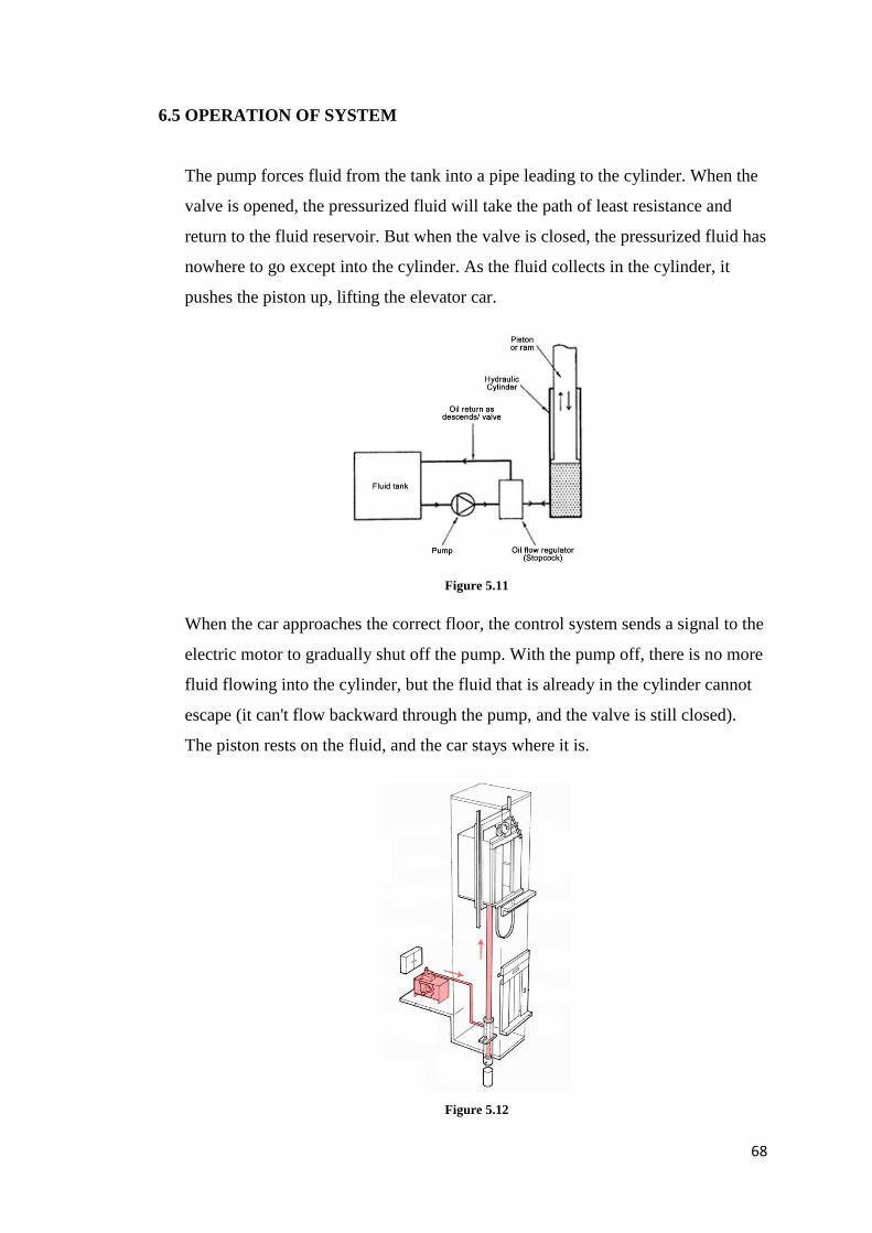
68
6.5 OPERATION OF SYSTEM
The pump forces fluid from the tank into a pipe leading to the cylinder. When the
valve is opened, the pressurized fluid will take the path of least resistance and
return to the fluid reservoir. But when the valve is closed, the pressurized fluid has
nowhere to go except into the cylinder. As the fluid collects in the cylinder, it
pushes the piston up, lifting the elevator car.
When the car approaches the correct floor, the control system sends a signal to the
electric motor to gradually shut off the pump. With the pump off, there is no more
fluid flowing into the cylinder, but the fluid that is already in the cylinder cannot
escape (it can't flow backward through the pump, and the valve is still closed).
The piston rests on the fluid, and the car stays where it is.
Figure 5.11
Figure 5.12
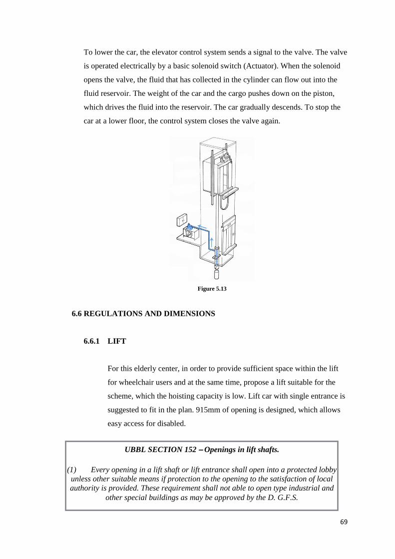
69
To lower the car, the elevator control system sends a signal to the valve. The valve
is operated electrically by a basic solenoid switch (Actuator). When the solenoid
opens the valve, the fluid that has collected in the cylinder can flow out into the
fluid reservoir. The weight of the car and the cargo pushes down on the piston,
which drives the fluid into the reservoir. The car gradually descends. To stop the
car at a lower floor, the control system closes the valve again.
6.6 REGULATIONS AND DIMENSIONS
6.6.1 LIFT
For this elderly center, in order to provide sufficient space within the lift
for wheelchair users and at the same time, propose a lift suitable for the
scheme, which the hoisting capacity is low. Lift car with single entrance is
suggested to fit in the plan. 915mm of opening is designed, which allows
easy access for disabled.
Figure 5.13
UBBL SECTION 152 – Openings in lift shafts.
(1) Every opening in a lift shaft or lift entrance shall open into a protected lobby
unless other suitable means if protection to the opening to the satisfaction of local
authority is provided. These requirement shall not able to open type industrial and
other special buildings as may be approved by the D. G.F.S.
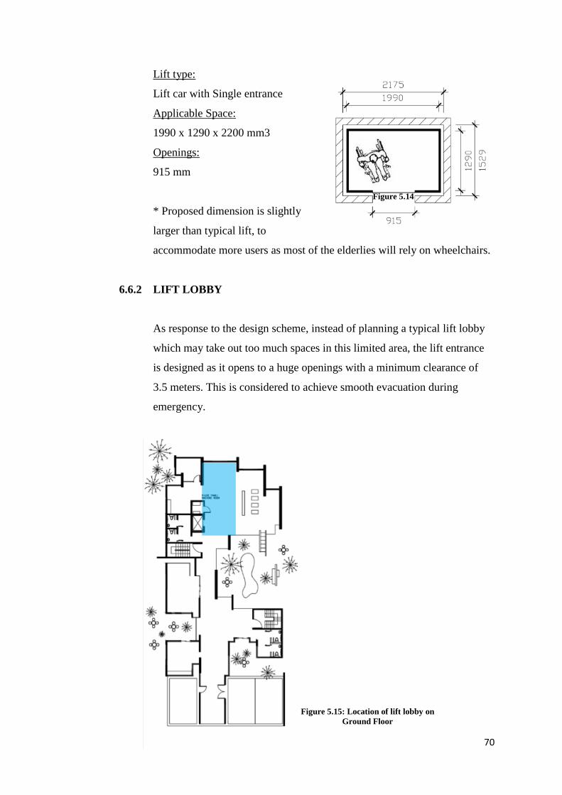
70
Lift type:
Lift car with Single entrance
Applicable Space:
1990 x 1290 x 2200 mm3
Openings:
915 mm
* Proposed dimension is slightly
larger than typical lift, to
accommodate more users as most of the elderlies will rely on wheelchairs.
6.6.2 LIFT LOBBY
As response to the design scheme, instead of planning a typical lift lobby
which may take out too much spaces in this limited area, the lift entrance
is designed as it opens to a huge openings with a minimum clearance of
3.5 meters. This is considered to achieve smooth evacuation during
emergency.
Figure 5.14
Figure 5.15: Location of lift lobby on
Ground Floor
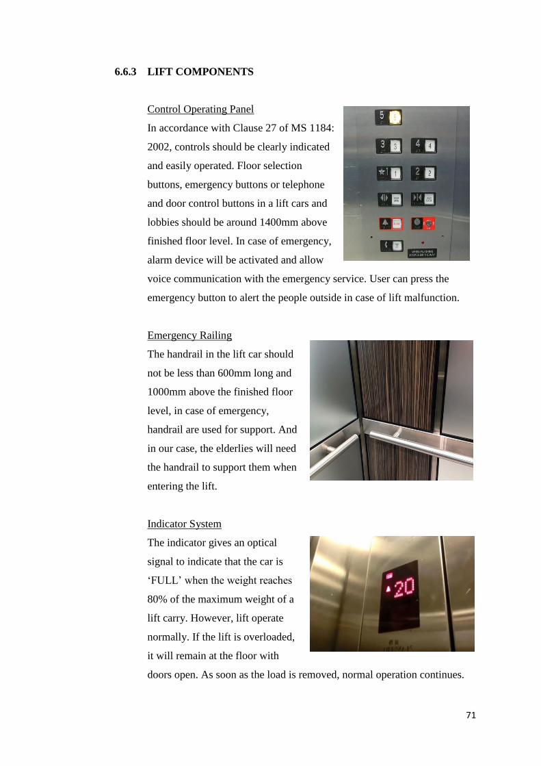
71
6.6.3 LIFT COMPONENTS
Control Operating Panel
In accordance with Clause 27 of MS 1184:
2002, controls should be clearly indicated
and easily operated. Floor selection
buttons, emergency buttons or telephone
and door control buttons in a lift cars and
lobbies should be around 1400mm above
finished floor level. In case of emergency,
alarm device will be activated and allow
voice communication with the emergency service. User can press the
emergency button to alert the people outside in case of lift malfunction.
Emergency Railing
The handrail in the lift car should
not be less than 600mm long and
1000mm above the finished floor
level, in case of emergency,
handrail are used for support. And
in our case, the elderlies will need
the handrail to support them when
entering the lift.
Indicator System
The indicator gives an optical
signal to indicate that the car is
‘FULL’ when the weight reaches
80% of the maximum weight of a
lift carry. However, lift operate
normally. If the lift is overloaded,
it will remain at the floor with
doors open. As soon as the load is removed, normal operation continues.
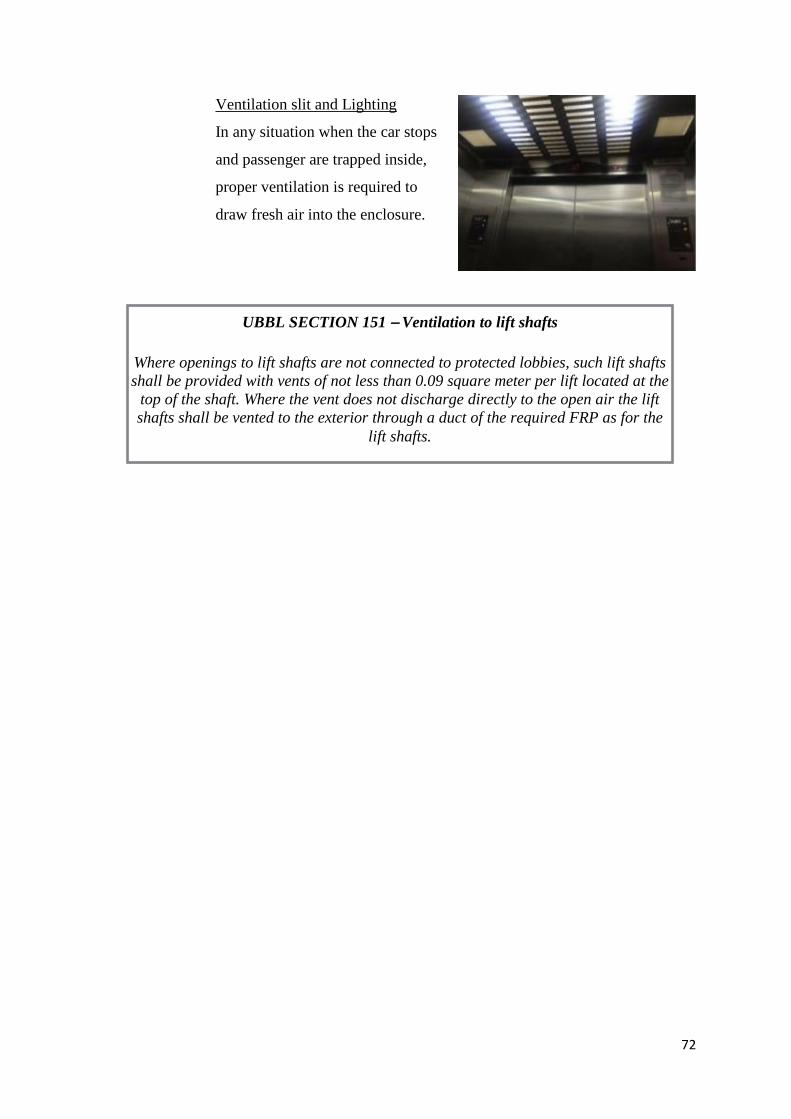
72
Ventilation slit and Lighting
In any situation when the car stops
and passenger are trapped inside,
proper ventilation is required to
draw fresh air into the enclosure.
UBBL SECTION 151 – Ventilation to lift shafts
Where openings to lift shafts are not connected to protected lobbies, such lift shafts
shall be provided with vents of not less than 0.09 square meter per lift located at the
top of the shaft. Where the vent does not discharge directly to the open air the lift
shafts shall be vented to the exterior through a duct of the required FRP as for the
lift shafts.
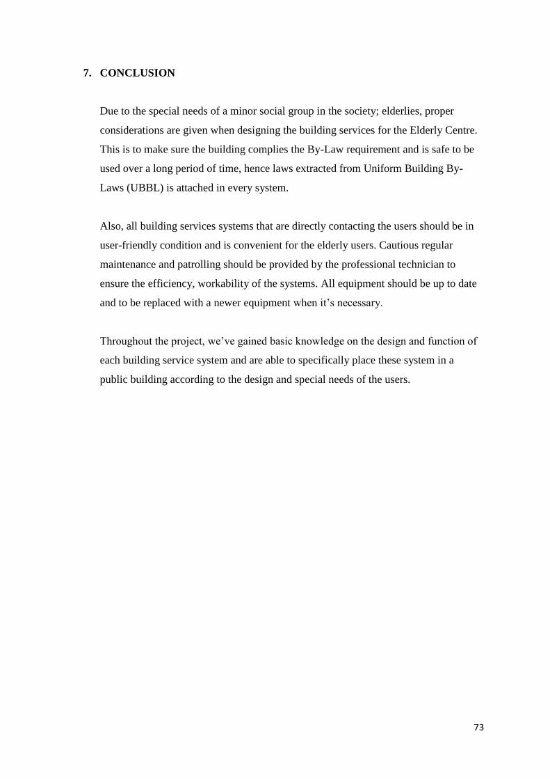
73
7. CONCLUSION
Due to the special needs of a minor social group in the society; elderlies, proper
considerations are given when designing the building services for the Elderly Centre.
This is to make sure the building complies the By-Law requirement and is safe to be
used over a long period of time, hence laws extracted from Uniform Building By-
Laws (UBBL) is attached in every system.
Also, all building services systems that are directly contacting the users should be in
user-friendly condition and is convenient for the elderly users. Cautious regular
maintenance and patrolling should be provided by the professional technician to
ensure the efficiency, workability of the systems. All equipment should be up to date
and to be replaced with a newer equipment when it’s necessary.
Throughout the project, we’ve gained basic knowledge on the design and function of
each building service system and are able to specifically place these system in a
public building according to the design and special needs of the users.
74
8. REFERENCES
8.1 ACTIVE FIRE PROTECTION
- A guide to Dry Powder fire extinguishers. (n.d.). Retrieved November 16, 2016, from
https://www.fireandsafetycentre.co.uk/advice-centre/a-guide-to-dry-powder-fire-
extinguishers/
- A. (2008, October 17). Panel Alerting. Retrieved November 16, 2016, from
http://firealarmcontrolpanel.blogspot.my
- Baker, T. (2015, August 28). Heat Detectors vs Smoke Detectors: What's the Difference? Retrieved
November 18, 2016, from https://www.systemsensorblog.com/2015/08/heat-detector-vs-
smoke-detector/
- BLOGS. (2012, December 21). Retrieved November 18, 2016, from
http://www.sharpfibre.com/blog/5/examining-the-relationship-between-active-and-passive-
fire-protection
- Chapter 6 FIRE FIGHTING SYSTEMS - Singapore Civil Defence ... (n.d.). Retrieved November 18, 2016,
from https://www.scdf.gov.sg/content/scdf_internet/en/building-
professionals/publications_and_circulars/fire_code_2002handbooks/_jcr_content/par/down
load_31/file.res/hb_v5_ch6.pdf
- Designed and Promoted by Maharashtra Industries Directory, www.maharashtradirectory.com. (n.d.). Fire
Hydrant System. Retrieved November 18, 2016, from http://www.fireknock.com/fire-
hydrant-system.html
- Dry Powder Extinguishers. (n.d.). Retrieved November 18, 2016, from
http://www.fireextinguisherguide.co.uk/types-of-fire-extinguishers/dry-powder-
extinguishers/
- Dry Powder Fire Extinguishers. (n.d.). Retrieved November 18, 2016, from http://www.mfs-fire-
extinguishers.co.uk/acatalog/Dry_Powder.html
- Dry/ Wet Riser Maintenance. (n.d.). Retrieved from http://www.chubb.co.uk/Documents/ws-
403/Assets/GCF554 Dry-Wet RiserLeaflet.pdf
- Electrical Info: Information on everything electrical and more! (n.d.). Retrieved November 23, 2016, from
http://electricalinfo.in/tech/fire-detection-alarm/
- Fire Alarm System Technical Specifications. (n.d.). Retrieved November 16, 2016, from
http://www.kentec.co.uk/specs_syncro.pdf
75
- FIRE SYSTEMS LTD - for a safer tomorrow. (2015, August 28). Retrieved November 18, 2016, from
http://www.firesystemsltd.co.uk/service/fire-alarm/design/system-components/optical-v-
ionisation-detectors
- GRUNDFOS. (n.d.). Retrieved November 18, 2016, from http://www.grundfos.com/service/encyclopedia-
search/fire-hose-reel-systems.html
- Goh, D., & Kuek, M. (2016, November 18). Overview of Fire Alarm Overview of Fire Alarm Systems and
Systems and Maintenance Maintenance. Lecture presented in Singapore. Retrieved
November 18, 2016, from https://www.scdf.gov.sg/content/scdf_internet/en/building-
professionals/fire-safety-manager/download_slides_forfsmbriefing-
26may09to9jul09/_jcr_content/par/download_1/file.res/FSMAS_Overview_of_Fire_Alarm
_Systems_&_Maintenance.pdf
- Haack, A. (2009, October). Active and passive fire protection – which way should we go ? Lecture
presented at International Conference on Operational Safety of Underground Facilities in
Turkey, Istanbul. Retrieved November 18, 2016, from
http://www.kgm.gov.tr/SiteCollectionDocuments/KGMdocuments/Otoyollar/YeraltiYapiIs
ltGuvSemineri/6Ekim/ActiveAndPassiveFireProtection.pdf
- Manual Call Point. (n.d.). Retrieved November 18, 2016, from
http://www.firesecurity.co.nz/services.php?id=edit4be8e3d3a968e
- McEwen, R. (1984, August 18). CBD-233. Fire Alarm and Detection Systems. Retrieved November 18,
2016, from http://www.cfaa.ca/Files/flash/CODES/FIRE ALARM ARTICLES FOR THE
AHJ/Fire Alarm and Detection Systems __irc.nrc-cnrc.gc.ca_pubs_cbd_cbd233-print_e.pdf
- Passive and active fire protection. (n.d.). Retrieved November 16, 2016, from
http://www.fireandwire.com.au/passive-vs-active-fire-protection/
- Passive Fire Protection vs. Active Fire Protection. (2015, July 7). Retrieved November 18, 2016, from
http://www.lifesafetyservices.com/active-vs-passive-fire-protection-2/
- Siting of Manual Call Points. (2011, August 22). Retrieved November 18, 2016, from
http://www.thesafetycentre.co.uk/blog/siting_of_manual_call_points.php
- System Smoke Detectors. (n.d.). Retrieved from http://www.systemsensor.com/en-
us/documents/system_smoke_detectors_appguide_spag91.pdf
8.2 PASSIVE FIRE PROTECTION
- Emergency Escape and Fire Fighting. Retrieved November 14, 2016, from
http://www.hsa.ie/eng/Topics/Fire/Emergency_Escape_and_Fire_Fighting/
76
- Fire & Exit Signs. Retrieved November 14, 2016, from http://www.seton.com/signs/fire-exit.html
- General fire safety. Retrieved November 14, 2016, from
http://www.hse.gov.uk/construction/safetytopics/generalfire.htm
- The Basics of Passive Fire Protection. Retrieved November 12, 2016, from
http://www.buildings.com/article-details/articleid/5851/title/the-basics-of-passive-fire-
protection-
- What is an exit route - emergency exit - Occupational. Retrieved November 16, 2016, from
https://www.osha.gov/OshDoc/data_General_Facts/emergency-exit-routes-factsheet.pdf
8.3 AIR CONDITIONING SYSTEM
- Ananthanarayanan, P. N. (2005). Basic Refrigeration and Air Conditioning. New Delhi: Tata McGraw-Hill.
- Darling, D. (n.d.). Air Conditioning. Retrieved November 15, 2016, from
http://www.daviddarling.info/encyclopedia/A/AE_air_conditioner.html
- Grondzik, W. T., & Kwok, A. G. (n.d.). Mechanical and Electrical Equipment for Buildings (Twelfth ed.).
Hoboken, New Jersey: John Wiley & Sons.
- Khemani, H., & Stonecrypher, L. (2009). Parts of the Window Air Conditioners. Retrieved November 15,
2016, from http://www.brighthubengineering.com/hvac/55186-parts-of-the-window-air-
conditioners-part-one/
- Khemani, H. (2013). Types of Air Conditioning Systems: Window, Split, Packaged and Central. Retrieved
November 13, 2016, from http://www.brighthubengineering.com/hvac/897-types-of-air-
conditioning-systems/
- Rubinoff, S. (2011, January 01). What is a Split Air Conditioner System? - Articles. Retrieved November
13, 2016, from http://www.networx.com/article/split-air-conditioner-system
8.4 MECHANICAL (AND NATURAL) VENTILATION SYSTEM
- Colourdot.co,. (2016). Bathroom Exhaust Fan Broan. Retrieved from http://weike1000.net/wp-
content/uploads/9/9-charming-bathroom-ventilation-fan-stopped-working.jpg
- Green Building Advisor,. (2016). Retrieved from
http://www.greenbuildingadvisor.com/sites/default/files/Bathroom%20exhaust%20fan%20
illustration%20-%20FHB.jpg
77
- Green Building Advisor,. (2016). Bathroom Exhaust Fan. Retrieved from
http://www.greenbuildingadvisor.com/sites/default/files/Bathroom%20exhaust%20fan%20
installation%20-%20FHB.jpg
- Home Tips.com,. (2016). Retrieved from http://www.hometips.com/wp-
content/uploads/2012/06/ceiling_fan_parts_diagram.gif?x49785
- InterNACHI,. (2016). Retrieved from
https://basc.pnnl.gov/sites/default/files/styles/large/public/images/HVAC61_kitchenexhaus
t1_PNNL_04-16-12.jpg
- Maria Papantoni, Author at TheGreenAge. (2016). TheGreenAge. Retrieved 15 November 2016, from
http://www.thegreenage.co.uk/author/maria-papantoni/
- Mr Duct Cleaning Services,. (2016). Retrieved from
http://lewisductclean.co.uk/images/extract_ventilation_system.jpg
- The Greenage,. (2016). Retrieved from http://www.thegreenage.co.uk/wp-content/uploads/2015/10/Roof-
ventilators.png
- Types of ventilation [ ]. (2016). Passipedia.org. Retrieved 15 November 2016, from
https://passipedia.org/planning/building_services/ventilation/basics/types_of_ventilation
- Whole Building Design Guide,. (2016). Retrieved from https://www.wbdg.org/images/11400_3.gif
8.5 MECHANICAL TRANSPORTATION SYSTEM
- Pictures: Figure 5.1, Figure 5.2, Figure 5.3, Figure 5.4
Retrieved from http://www.electrical-knowhow.com/2012/04/elevators-types-and-classification-part.html
- Grondzik, W. T., & Kwok, A. G. (2015). Mechanical and electrical equipment for buildings. Hoboken, NJ:
Wiley.
- Neufert, E., Neufert, P., & Kister, J. (2012). Architects' data. Chichester, West Sussex, UK: Wiley-
Blackwell.
- Uniform Building By-Laws, 1984 (G.N. 5178/85): As at 25th April 1990. (1990). Kuala Lumpur:
International Law Book Services.
78
10. APPENDIX


![[DRAFT, PRE-FINAL OR FINAL] REPORT - OECD](https://img.pdfslide.us/doc/110x75/5ec770f8c7c9f9670a3f7375/-draft-pre-final-or-final-report-.jpg)