Embed Size (px)
Citation preview
* GB784788 (A)
Description: GB784788 (A) ? 1957-10-16
Improvements in or relating to lanterns for signalling
Description of GB784788 (A)
We, THE GENERAL ELECTRIC COMPANY LIMITED, of Magnet House, Kingsway, London, W C 2, a British Company, and JOHN COUCH ADAMS, of the same address, a British Subject, do hereby declare the invention, for which we pray that a patent may be granted to us, and the method by which it is to be performed, to be particularly des- cribed in and by the following statement: - This invention relates to lanterns for signalling to an observer by means of intermittent interruptions of the light emitted from the lantern, of the kind including a concave mirror, socket means for supporting an electric lamp with its light source substantially at the focus of the mirror for producing a beam of light directed along the axis of the mirror in use of the lantern, a movable shutter, and control means for operating the shutter between a closed position in which the shutter is arranged for preventing the emission of light from the lantern by obstruction of the light, and an open position in which the obstruction is removed so that light can emerge from the lantern. The main object of the invention is to provide a lantern of this kind incorporating a simple and efficient shutter arrangement by means of which a rapid signalling action can be obtained, and a further object is to provide a lantern which incorporates a builtin colour filter arrangement yet can be constructed in a light-weight form which is convenient and easy to handle for rapid signalling. According to the invention, in a lantern of the kind referred to the shutter consists of a pair of substantially plane plates each mounted for rotation about an axis which is substantially perpendicular to the mirror axis and lies between the mirror and its focus lPrice 3 s 6 d l on or close to the mirror axis, and the control means is arranged to rotate said plates simultaneously in opposite directions about said
axes between a shutter-closed position in which the plates lie substantially in a common plane perpendicular to the mirror axis so as to provide between the lamp and the mirror in use of the apparatus a screen which prevents the light from the lamp reaching the mirror, and a shutter-open position in which the plates lie parallel to the mirror axis so as to permit light from the lamp to reach the mirror. Preferably the plate axes are arranged to lie nearer to the mirror focus than to the mirror In this way it can be arranged that relatively small plates, which can be quickly operated, can be used whilst still efficiently screening the mirror from the light source. Preferably the two shutter plates axes are coincident and intersect the mirror axis, the plates thus sharing a common axis so as to form a butterfly-wing type of shutter. Usually it will be necessary or desirable for the lantern to incorporate a shield on the side of the mirror focus away from the mirror arranged to intercept light from the lamp which would be emitted directly from the lantern, that is to say without reflection from the mirror Such a shield might not be necessary if the lamp used was arranged to emit light only towards the mirror, or if the circumstances were such that such direct emission of light was tolerable or desired, for example for marking the signalling point, and did not prevent recognition of the signalling action. Preferably the control means includes a snap-action mechanism arranged to move between two rest positions, and in a direction parallel to the axis of the mirror, a pair of arms which extend parallel to the mirror 784,788 PATENT SPECIFICATION Date of fling Complete Specification: Dec 6, 19-55 Application Date: Sept 6, 1954 No 25856154. Complete Specification Published: Oct 16, 1957. Index at Acceptncoo:-Class 7 '5 ( 4), C( 8 H 2: 22 DX). International Classification:-F 21 b. COMPLETE SPECIFICATION. Improvements in or relating to Lanterns for Signalling. 784,788 axis and are resilient against spreading away from each other, each of said arms being linked with a different one of the shutter plates by a connection to a lug which extends j from the plate on the side remote from the mirror, the point of connection being such that a rotation of the plates between the shutter-open and shutter-closed positions, in either direction, is accompanied by an initial spreading of the arms against their resilience followed by a closing of the arms assisted by said resilience which produces a second snap-action assisting the rapid attainment of the open and closed positions of the shutters. For providing a built-in colour filter arrangement which is easy to
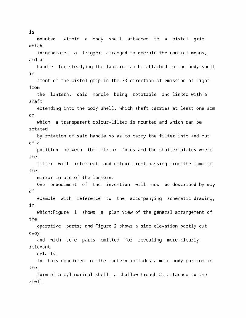
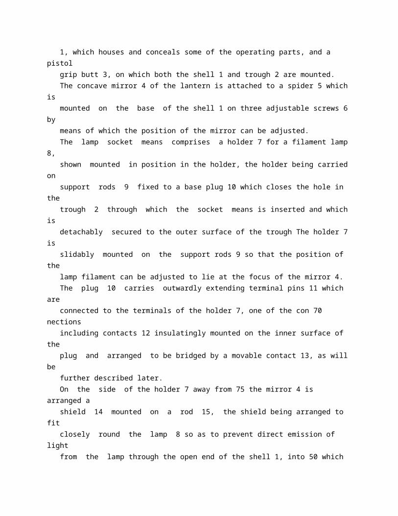
operate in conjunction with convenient control of the signalling action, the lantern can be constructed so that the optical system is mounted within a body shell attached to a pistol grip which incorporates a trigger arranged to operate the control means, and a handle for steadying the lantern can be attached to the body shell in front of the pistol grip in the 23 direction of emission of light from the lantern, said handle being rotatable and linked with a shaft extending into the body shell, which shaft carries at least one arm on which a transparent colour-lilter is mounted and which can be rotated by rotation of said handle so as to carry the filter into and out of a position between the mirror focus and the shutter plates where the filter will intercept and colour light passing from the lamp to the mirror in use of the lantern. One embodiment of the invention will now be described by way of example with reference to the accompanying schematic drawing, in which:Figure 1 shows a plan view of the general arrangement of the operative parts; and Figure 2 shows a side elevation partly cut away, and with some parts omitted for revealing more clearly relevant details. In this embodiment of the lantern includes a main body portion in the form of a cylindrical shell, a shallow trough 2, attached to the shell 1, which houses and conceals some of the operating parts, and a pistol grip butt 3, on which both the shell 1 and trough 2 are mounted. The concave mirror 4 of the lantern is attached to a spider 5 which is mounted on the base of the shell 1 on three adjustable screws 6 by means of which the position of the mirror can be adjusted. The lamp socket means comprises a holder 7 for a filament lamp 8, shown mounted in position in the holder, the holder being carried on support rods 9 fixed to a base plug 10 which closes the hole in the trough 2 through which the socket means is inserted and which is detachably secured to the outer surface of the trough The holder 7 is slidably mounted on the support rods 9 so that the position of the lamp filament can be adjusted to lie at the focus of the mirror 4. The plug 10 carries outwardly extending terminal pins 11 which are connected to the terminals of the holder 7, one of the con 70 nections including contacts 12 insulatingly mounted on the inner surface of the plug and arranged to be bridged by a movable contact 13, as will be further described later. On the side of the holder 7 away from 75 the mirror 4 is arranged a shield 14 mounted on a rod 15, the shield being arranged to fit closely round the lamp 8 so as to prevent direct emission of light from the lamp through the open end of the shell 1, into 50 which end is fitted an annular sleeve carrying a glass closure plate 16. Between the mirror 4 and the holder 7 are arranged a pair of
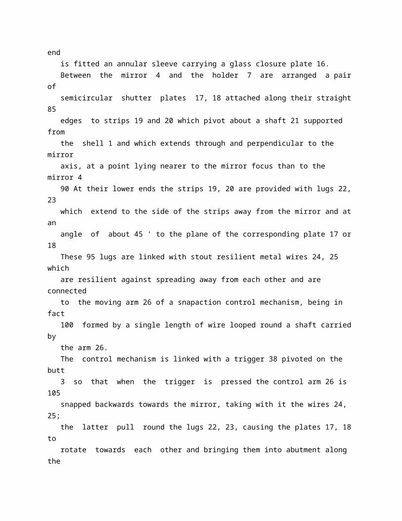
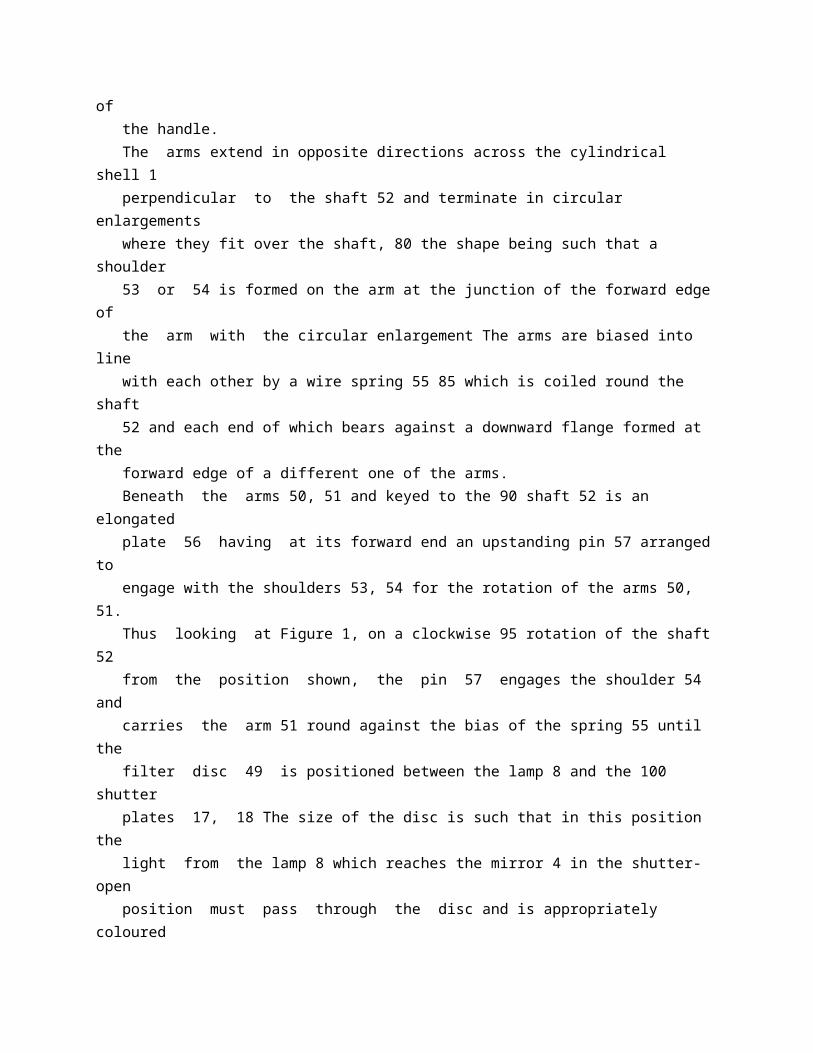
semicircular shutter plates 17, 18 attached along their straight 85 edges to strips 19 and 20 which pivot about a shaft 21 supported from the shell 1 and which extends through and perpendicular to the mirror axis, at a point lying nearer to the mirror focus than to the mirror 4 90 At their lower ends the strips 19, 20 are provided with lugs 22, 23 which extend to the side of the strips away from the mirror and at an angle of about 45 ' to the plane of the corresponding plate 17 or 18 These 95 lugs are linked with stout resilient metal wires 24, 25 which are resilient against spreading away from each other and are connected to the moving arm 26 of a snapaction control mechanism, being in fact 100 formed by a single length of wire looped round a shaft carried by the arm 26. The control mechanism is linked with a trigger 38 pivoted on the butt 3 so that when the trigger is pressed the control arm 26 is 105 snapped backwards towards the mirror, taking with it the wires 24, 25; the latter pull round the lugs 22, 23, causing the plates 17, 18 to rotate towards each other and bringing them into abutment along the axis 110 of the mirror As the plates rotate, the movement of the lugs first spreads the wires 24, 25 apart, and as the lugs pass beyond the diametrically opposed position the distance between the pivot points of the 115 wires on the lugs decreases and the resilience of the wires assists the closing together of the plates. The arm 26 is biased by a spring 40 to the position shown on the drawing, so that 120 when the trigger 38 is released, the arm 26 moves forward away from the mirror, carrying the wires 24, 25 forward and rotating the shutters 17, 18 back to the coplanar position shown, when the resilience of the 125 wires 24, 25 again assists the attainment of the final position after lugs 22, 23 have passed the diametrically opposed position. The arm 26 consists of a pair of parallel side-plates 27, 28 connected by a head 29 130 the operator to direct the beam of light from 65 the lantern on to the required target. The handle 45 is arranged to serve also as the control means for a colour-filter mechanism built into the body of the lantern. This mechanism includes a pair of coloured 70 transparent discs 48, 49 each mounted on an arm 50, 51 which is a loose fit on a shaft 52 which extends perpendicularly through the centre of the trough 2 into the handle 45, being keyed thereto so as to be rotatable 75 by rotation of the handle. The arms extend in opposite directions across the cylindrical shell 1 perpendicular to the shaft 52 and terminate in circular enlargements where they fit over the shaft, 80 the shape being such that a shoulder 53 or 54 is formed on the arm at the junction of the forward edge of the arm with the circular enlargement The arms are biased into line
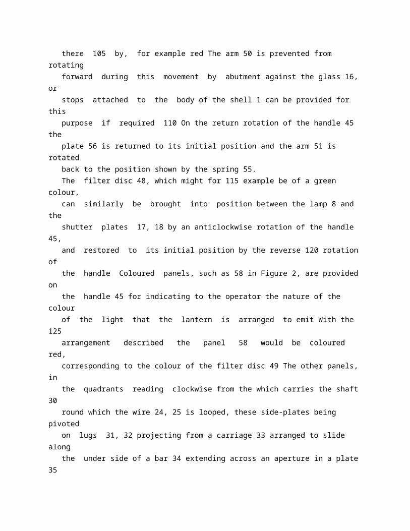
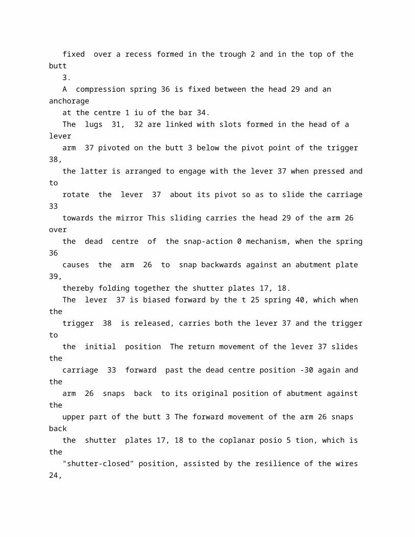
with each other by a wire spring 55 85 which is coiled round the shaft 52 and each end of which bears against a downward flange formed at the forward edge of a different one of the arms. Beneath the arms 50, 51 and keyed to the 90 shaft 52 is an elongated plate 56 having at its forward end an upstanding pin 57 arranged to engage with the shoulders 53, 54 for the rotation of the arms 50, 51. Thus looking at Figure 1, on a clockwise 95 rotation of the shaft 52 from the position shown, the pin 57 engages the shoulder 54 and carries the arm 51 round against the bias of the spring 55 until the filter disc 49 is positioned between the lamp 8 and the 100 shutter plates 17, 18 The size of the disc is such that in this position the light from the lamp 8 which reaches the mirror 4 in the shutter-open position must pass through the disc and is appropriately coloured there 105 by, for example red The arm 50 is prevented from rotating forward during this movement by abutment against the glass 16, or stops attached to the body of the shell 1 can be provided for this purpose if required 110 On the return rotation of the handle 45 the plate 56 is returned to its initial position and the arm 51 is rotated back to the position shown by the spring 55. The filter disc 48, which might for 115 example be of a green colour, can similarly be brought into position between the lamp 8 and the shutter plates 17, 18 by an anticlockwise rotation of the handle 45, and restored to its initial position by the reverse 120 rotation of the handle Coloured panels, such as 58 in Figure 2, are provided on the handle 45 for indicating to the operator the nature of the colour of the light that the lantern is arranged to emit With the 125 arrangement described the panel 58 would be coloured red, corresponding to the colour of the filter disc 49 The other panels, in the quadrants reading clockwise from the which carries the shaft 30 round which the wire 24, 25 is looped, these side-plates being pivoted on lugs 31, 32 projecting from a carriage 33 arranged to slide along the under side of a bar 34 extending across an aperture in a plate 35 fixed over a recess formed in the trough 2 and in the top of the butt 3. A compression spring 36 is fixed between the head 29 and an anchorage at the centre 1 iu of the bar 34. The lugs 31, 32 are linked with slots formed in the head of a lever arm 37 pivoted on the butt 3 below the pivot point of the trigger 38, the latter is arranged to engage with the lever 37 when pressed and to rotate the lever 37 about its pivot so as to slide the carriage 33 towards the mirror This sliding carries the head 29 of the arm 26 over the dead centre of the snap-action 0 mechanism, when the spring 36 causes the arm 26 to snap backwards against an abutment plate 39, thereby folding together the shutter plates 17, 18.
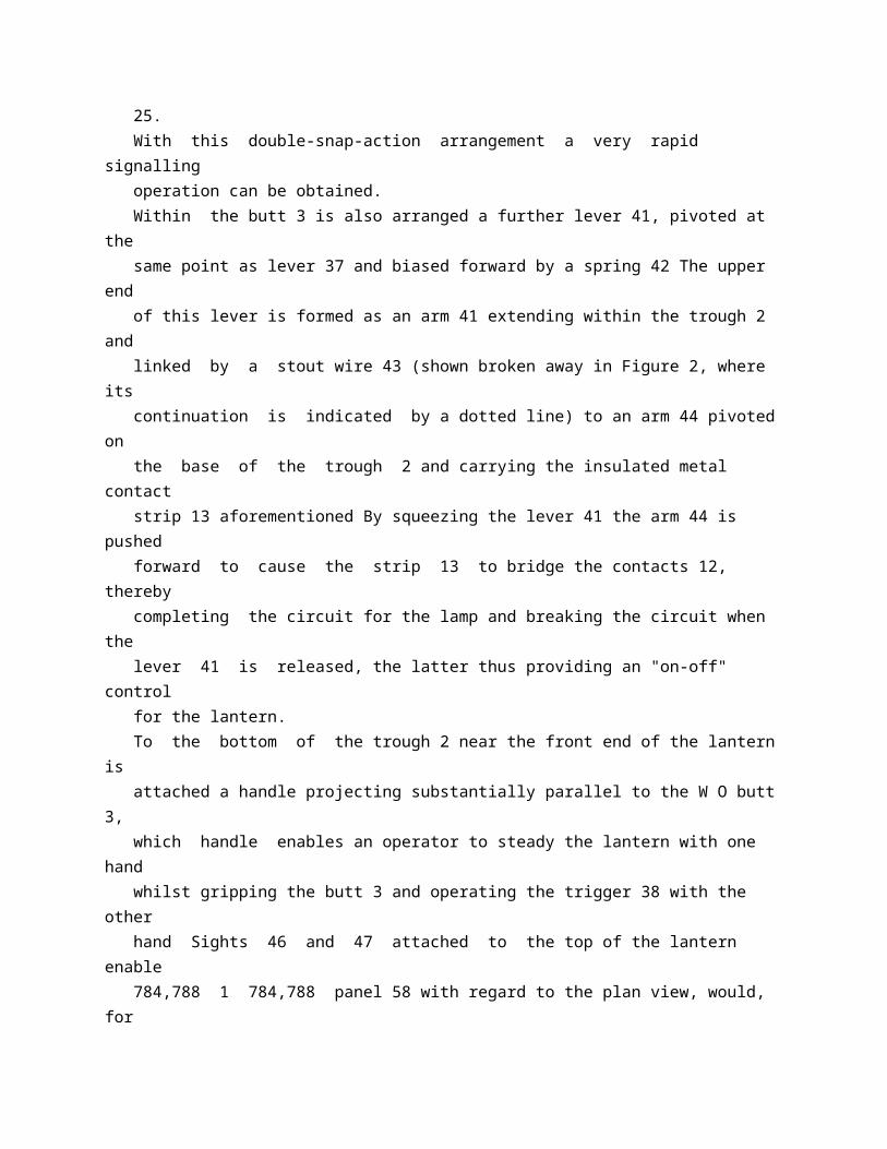
The lever 37 is biased forward by the t 25 spring 40, which when the trigger 38 is released, carries both the lever 37 and the trigger to the initial position The return movement of the lever 37 slides the carriage 33 forward past the dead centre position -30 again and the arm 26 snaps back to its original position of abutment against the upper part of the butt 3 The forward movement of the arm 26 snaps back the shutter plates 17, 18 to the coplanar posio 5 tion, which is the "shutter-closed" position, assisted by the resilience of the wires 24, 25. With this double-snap-action arrangement a very rapid signalling operation can be obtained. Within the butt 3 is also arranged a further lever 41, pivoted at the same point as lever 37 and biased forward by a spring 42 The upper end of this lever is formed as an arm 41 extending within the trough 2 and linked by a stout wire 43 (shown broken away in Figure 2, where its continuation is indicated by a dotted line) to an arm 44 pivoted on the base of the trough 2 and carrying the insulated metal contact strip 13 aforementioned By squeezing the lever 41 the arm 44 is pushed forward to cause the strip 13 to bridge the contacts 12, thereby completing the circuit for the lamp and breaking the circuit when the lever 41 is released, the latter thus providing an "on-off" control for the lantern. To the bottom of the trough 2 near the front end of the lantern is attached a handle projecting substantially parallel to the W O butt 3, which handle enables an operator to steady the lantern with one hand whilst gripping the butt 3 and operating the trigger 38 with the other hand Sights 46 and 47 attached to the top of the lantern enable 784,788 1 784,788 panel 58 with regard to the plan view, would, for use with an ordinary filament lamp and green filter disc 48, be coloured white and green respectively. S At its lower end, where the shaft 52 passes through the base of the trough 2, a circular plate 59 is keyed to the shaft, which plate carries upstanding pins 60, 61 arranged to engage with a stop 62 fixed to the base of the trough for limiting the rotational movement of the shaft to that required to bring the filter discs into the operative position. Holes formed in the base of the plate 59 are arranged to engage with balls 63 set into the base of the trough 2 for providing a positive "click" indication of the operative and rest positions of the filter discs. The internal surface of the shell, and the surfaces of parts within the shell, in particular the surfaces of the shutter plates 17, 18, are given a dull black finish for reducing the amount of stray light emitted from the lantern in use thereof.
By constructing the shell 1, the butt 3 and other metal parts of the lantern as far as possible of aluminium, a very light construction can be obtained that can be readily handled and used for long periods by an operator without fatigue.
* Sitemap * Accessibility * Legal notice * Terms of use * Last updated: 08.04.2015 * Worldwide Database * 5.8.23.4; 93p
* GB784789 (A)
Description: GB784789 (A) ? 1957-10-16
Improvements relating to chimney cowls
Description of GB784789 (A)
PATENT SPECIFICATION Date of filing Complete Specification: Oct 4, 1955. Application Date: Oct 26, 1954 No 30821154. Complete Specification Published: Oct 16, 1957. Index at Acceptance:-Class 25, A( 13 18: 21). International Classification:-F 231. COMPLETE SPECIFICATION. Improvements relating to Chimney Cowls. I, FREDERIC NORMAN HOULDSWORTH, a British Subject, of 12 Hounsfield Road, Sheffield 3, do hereby declare the invention, for which I pray that a patent may be granted to me, and the method by which it is to be performed, to be particularly described in and by the following statement:- This invention has for its object to provide an improved type of cowl for fixing on a chimney for the purpose of preventing downdraughts and enabling smoke to be carried away more effectively. According to the invention, a cowl adapted to be mounted on a chimney
pot has a tubular member with an outwardly directed flange around its upper edge and means for deflecting wind upwards towards said flange, vertical plates arranged with their lower parts around and spaced from the upper end of the tubular member, with gaps between their vertical edges which edges extend above the top of the tubular member, and a cover plate above the vertical plates. The tubular member may be arranged to spigot into the end of a chimney pot, and may have a frusto-conical shaped wind deflector, flaring outwards and downwards, adapted to come just above the level of the top of the chimney pot when the cowl is attached thereto to which deflector may be attached straps for securing the cowl in position The flange at the top of the tubular member may be about A inch wide and brackets for the vertical plates may be attached to the flange or the top of the tubular member. There may be four or more vertical plates and their vertical edge parts may be bent outwards so as to form convergent parts defining apertures between the plates Each plate may be tapered to a point at the bottom, the point being below the top of the lPrice 3 s 6 d l tubular member while the vertical edges terminate above the top of the tubular member. The cowl may be made of metal, earthenware, asbestos cement or any other suitable material. The wind deflector deflects the wind upwards against the flange, which causes it to flow outwards away from the cowl, and to pass through the gaps between the vertical plates, drawing the smoke away from the chimney pot. Referring to the accompanying drawings: Figure 1 is a side elevation of a chimney cowl in accordance with the invention. Figure 2 is a perspective view. Figure 3 is a plan view, partly in section. The chimney cowl comprises a tubular member 1, the lower end of which is adapted to spigot into the topof a chimney pot A frustoconical shaped wind deflector 2 flaring outwards and downwards is fixed on the tubular member 1, adapted to come just above the level of the top of the chimney pot when the cowl is attached thereto At the top of the tubular member 1 is an outwardly directed flange 3, and there are brackets 4 secured to the member 1 for supporting four vertical plates 5 and spacing them from the flange 3. The plates 5 are tapered to a point at the bottom, and have their vertical edge parts bent outwards to form convergent parts defining apertures between the plates, there being gaps between the outer edges of the convergent parts of neighbouring plates. The pointed lower ends of the plates 5 are below the level of the
flange 3, while the vertical edges terminate above the level of the flange 3 The top of the cowl is closed by a cover Dlate 6 secured to the top edges of the plates 5.
* Sitemap * Accessibility * Legal notice * Terms of use * Last updated: 08.04.2015 * Worldwide Database * 5.8.23.4; 93p
* GB784790 (A)
Description: GB784790 (A) ? 1957-10-16
Improvements in apparatus for inverting sheet-like articles, for exampleduring delivery
Description of GB784790 (A)
COMPLETE SPECIFICATION llXprovemnts in Appratus for Illvertlng SheetS e Articles, for exaiinple During Delivery We, IGRANIC ELECTRIC COMPANY LIMITED, a British Company, of Elstow Road, Bedford, in the County of Bedford, do hereby declare the invention, for which we pray that a patent may be granted to us, and the method by which it is to be performed, to be particularly described in and by the following statement:- This invention relates to apparatus for inverting sheet-like articles, and it relates more particularly to means for inverting and counting newspapers and the like. In handling sheet-like articles it is often important that such articles be arranged with certain edges thereof extending in a given direction. For example, it is often necessary to invert newspapers or magazines after they leave the press so that the cut edge or the folded edge thereof, whichever leads at first thereafter trails. An object of this invention is to provide improved apparatus for inverting articles of the afore-described character.
Another object is to provide improved apparatus for inverting sheet-like articles and for counting the number of articles which are inverted. The invention comprises mechanism for inverting a succession of sheet-like articles each having a leading portion and a trailing portion, comprising conveyor means to carry said articles in one direction with the lead- ing portions forward, conveyor means to carry said articles in a direction opposite to said one direction with the trailing portions forwards, and positively operating transfer means to transfer the trailing portions of said articles from said first mentioned conveyor means to said second mentioned conveyor means. The invention further comprises mechanism for inverting a succession of sheet-like articles conveyed by a main conveyor, each article having a leading portion and a trailing portion and initially having its leading portion forwards, comprising conveyor means to receive said articles from said main conveyor and carry them, with their leading portions still forwards, in one direction, conveyor means to carry said articles in a direction opposite to said one direction with the trailing portions forwards and to return them with their trailing portions forwards to said main conveyor, and means whereby the trailing portions of said articles are transferred from said first mentioned conveyor means to said second mentioned conveyor means. The invention further comprises mechanism for inverting and counting a succession of sheet-like articles each having a leading portion and a trailing portion, comprising conveyor means to carry said articles in one direction with the leading portions forward, conveyor means to carry said articles in a direction opposite to said one direction with the trailing portions forwards, means whereby the trailing portions of said articles are transferred from said first mentioned conveyor means to said second mentioned conveyor means, counting mechanism including a light source and a light impulse counter having a light pick-up device, said light source and said pick-up device being located on opposite sides of the position at which reversal of the forward ends of the articles from said one direction to said opposite direction takes place, whereby said leading portions interrupt passage of light from said light source to said pick-up device and the number of articles inverted is counted. The accompanying drawings illustrate certain embodiments of the invention which will now be described. In the drawings, Figure 1 is a schematic illustration of an inverting and counting unit embodying the invention; Fig. 2 is a schematic illustration of an alternative form of inverting unit embodying the invention; and Fig. 3 is a schematic illustration of another alternative form of
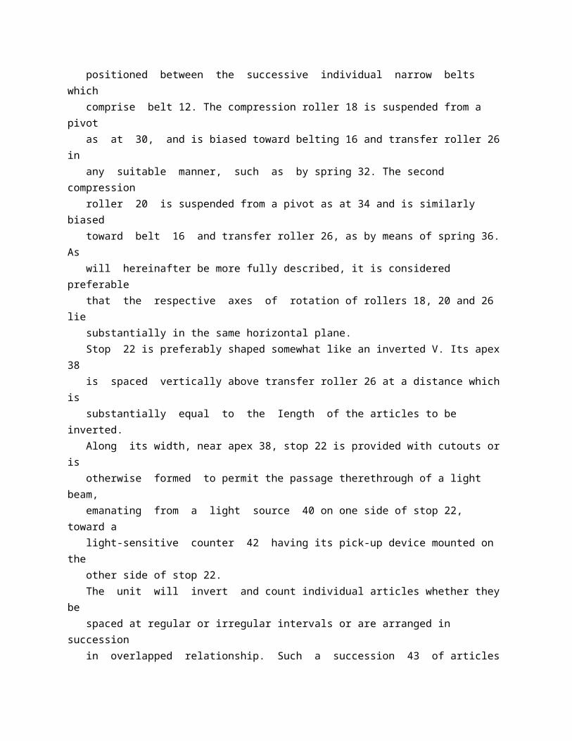
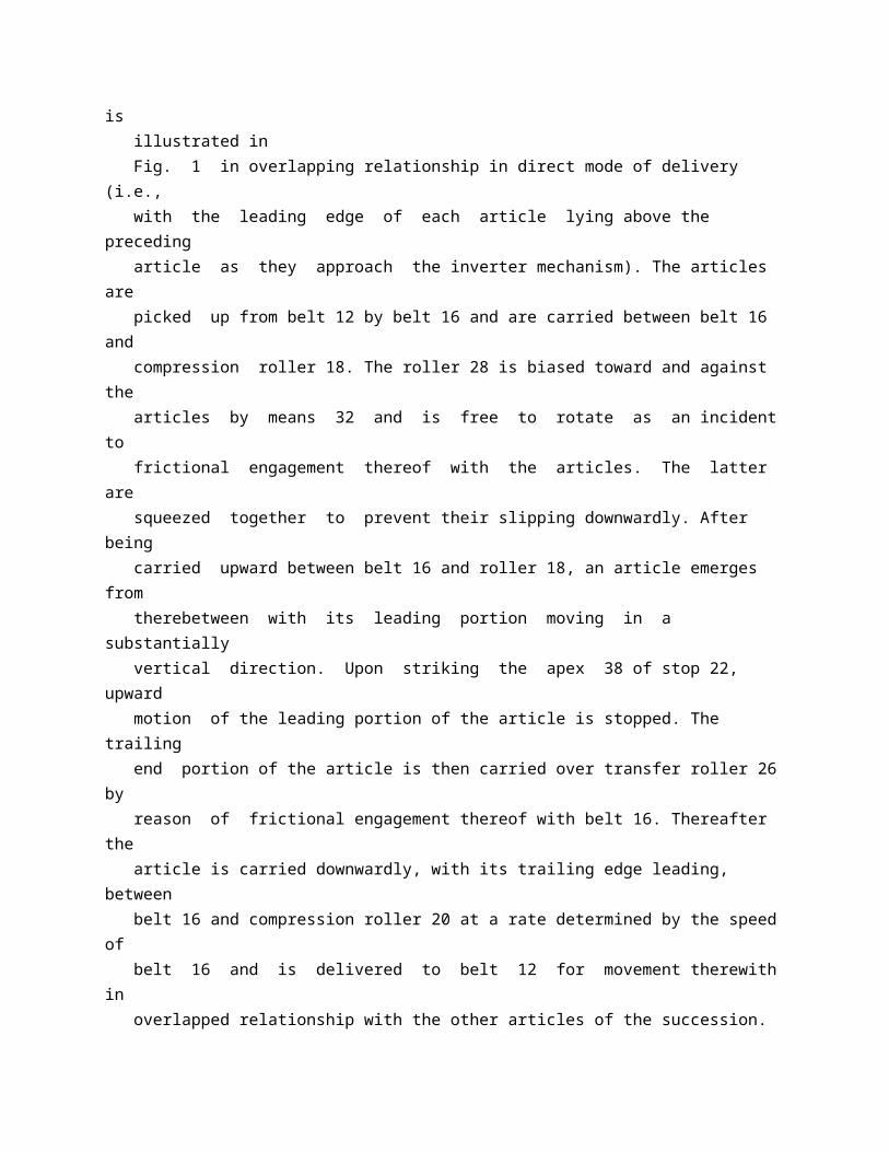
inverting unit embodying the invention. Referring to Fig. 1 the numeral 10 generally designates suitable conveyor mechanism comprising belting 12 and rollers 14 adapted to carry a succession of sheetlike articles such as newspapers, pamphlets, flexible containers, etc., toward the inverting and counting mechanism from the right, in the drawing, and away therefrom toward the left. The belting 12 preferably comprises a plurality of narrow belts of a well known form arranged in parallel relationship and suitably spaced apart from each other. The inverter mechanism includes an endless pick-up and delivery belt 16, a compression roller 18, a second compression roller 20 and a stop or abutment means 22. The belt 16 is preferably in the form of a plurality of narrow belts arranged in parallel relationship and suitably spaced apart from each other. It extends over a drive roller 24, a transfer roller 26, and an idler roller 28. The transfer roller 26 is positioned above belting 12 of conveyor 10 and the drive roller 14 and idler roller 28 are positioned below the upper, working side of belt 12. The individual narrow belts which comprise belt 16 are preferably positioned between the successive individual narrow belts which comprise belt 12. The compression roller 18 is suspended from a pivot as at 30, and is biased toward belting 16 and transfer roller 26 in any suitable manner, such as by spring 32. The second compression roller 20 is suspended from a pivot as at 34 and is similarly biased toward belt 16 and transfer roller 26, as by means of spring 36. As will hereinafter be more fully described, it is considered preferable that the respective axes of rotation of rollers 18, 20 and 26 lie substantially in the same horizontal plane. Stop 22 is preferably shaped somewhat like an inverted V. Its apex 38 is spaced vertically above transfer roller 26 at a distance which is substantially equal to the Iength of the articles to be inverted. Along its width, near apex 38, stop 22 is provided with cutouts or is otherwise formed to permit the passage therethrough of a light beam, emanating from a light source 40 on one side of stop 22, toward a light-sensitive counter 42 having its pick-up device mounted on the other side of stop 22. The unit will invert and count individual articles whether they be spaced at regular or irregular intervals or are arranged in succession in overlapped relationship. Such a succession 43 of articles is illustrated in Fig. 1 in overlapping relationship in direct mode of delivery (i.e., with the leading edge of each article lying above the preceding article as they approach the inverter mechanism). The articles are picked up from belt 12 by belt 16 and are carried between belt 16 and
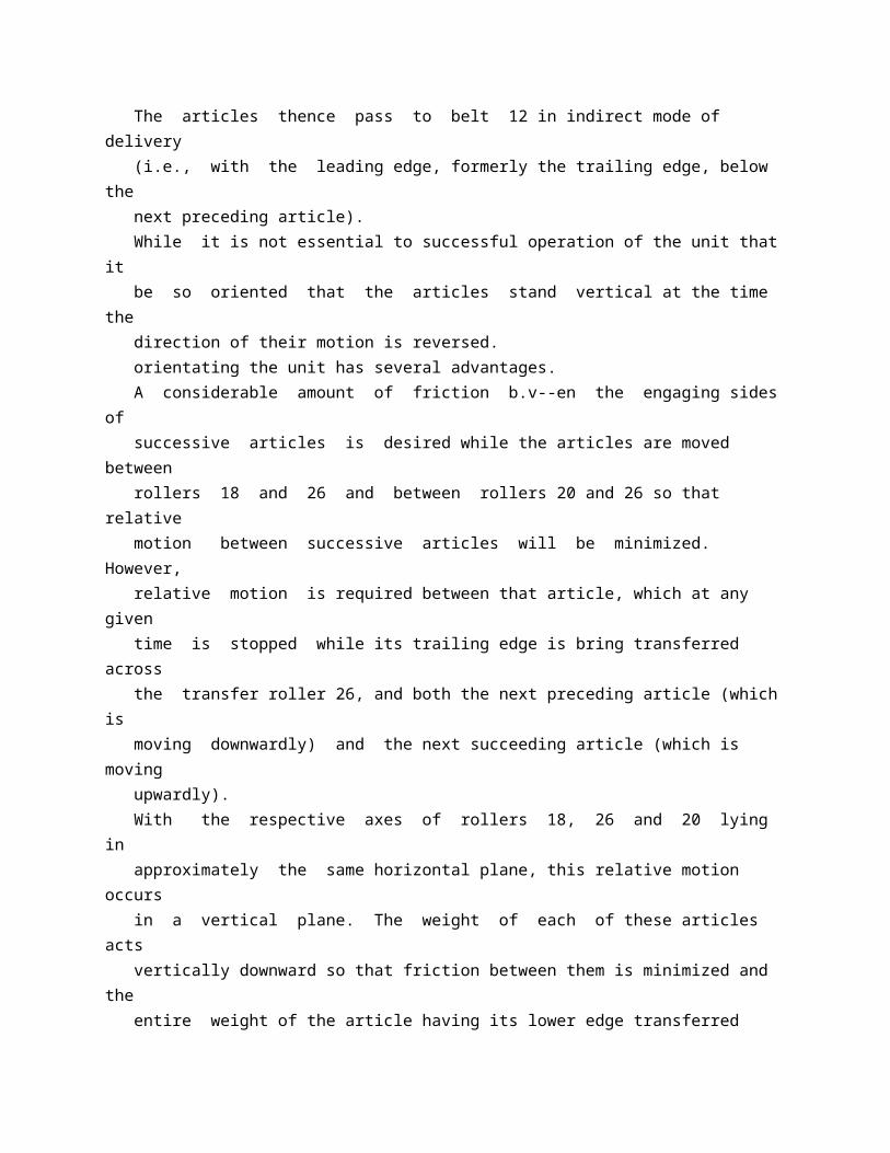
compression roller 18. The roller 28 is biased toward and against the articles by means 32 and is free to rotate as an incident to frictional engagement thereof with the articles. The latter are squeezed together to prevent their slipping downwardly. After being carried upward between belt 16 and roller 18, an article emerges from therebetween with its leading portion moving in a substantially vertical direction. Upon striking the apex 38 of stop 22, upward motion of the leading portion of the article is stopped. The trailing end portion of the article is then carried over transfer roller 26 by reason of frictional engagement thereof with belt 16. Thereafter the article is carried downwardly, with its trailing edge leading, between belt 16 and compression roller 20 at a rate determined by the speed of belt 16 and is delivered to belt 12 for movement therewith in overlapped relationship with the other articles of the succession. The articles thence pass to belt 12 in indirect mode of delivery (i.e., with the leading edge, formerly the trailing edge, below the next preceding article). While it is not essential to successful operation of the unit that it be so oriented that the articles stand vertical at the time the direction of their motion is reversed. orientating the unit has several advantages. A considerable amount of friction b.v--en the engaging sides of successive articles is desired while the articles are moved between rollers 18 and 26 and between rollers 20 and 26 so that relative motion between successive articles will be minimized. However, relative motion is required between that article, which at any given time is stopped while its trailing edge is bring transferred across the transfer roller 26, and both the next preceding article (which is moving downwardly) and the next succeeding article (which is moving upwardly). With the respective axes of rollers 18, 26 and 20 lying in approximately the same horizontal plane, this relative motion occurs in a vertical plane. The weight of each of these articles acts vertically downward so that friction between them is minimized and the entire weight of the article having its lower edge transferred across roller 26 by belting 16 is utilized to increase friction between said lower edge and belting 16 where- by the transfer is made with maximum efficiency. Transfer roller 26 is preferably of relatively small diameter although the diameter is not a critical factor. Pivotal mounting of compression rollers 18 and 20 and the provision of means to bias said rollers inwardly, enables the unit to handle articles of various thicknesses without alteration of the unit. When used in conjunction with a newspaper conveyor, no adjustment is
required to compensate for changes in the thickness of successive issues of the newspaper. The count obtained by counting the number of times the light beam is interrupted by articles approaching stop 22, is very accurate. Assuming the articles are newspapers arranged in overlapping relationship with each paper leading the successive one three inches, the separation between apex 38 and the point below the apex 38 at which the edges of adjacent papers will coincide is one and one-half inches. This spacing is ample to afford sufficient time intervals between interruptions of the light beam for accurate counting at the highest newspaper conveyor speeds. It will be apparent that various modifications may be made in the scheme illustrated with respect to the relative sizes of the various rollers, the angles at which the articles are picked up from and delivered to the main conveyor and the arrangement of the idler and drive rollers, to accommodate articles of various sizes and degrees of flexibility and depending upon the space available for the inverter and counter, etc. One modified form of inverter is shown in Fig. 2. This unit comprises a drive belt 50 extending around a transfer roller 52 and idler rollers 54 and 56 which form part of a main conveyor comprising, in addition, belts 58a and 58b. The unit further includes a pick-up belt 60 driven on rollers 62 and 64 and a delivery belt 66 driven on rollers 68 and 70 by frictional engagement with the articles to be inverted, and a stop 72 mounted in line with and above transfer roller 52. Rollers 62 and 64 are mounted at fixed points on one side of and respectively below and above roller 52. Rollers 68 and 70 are mounted at fixed points on the other side of and respectively below and above roller 52. Articles to be inverted are delivered to the inverter on belt 58a, are then picked up by belt 50, and moved upwardly and held against slipping by belts 50 and 60; and are then projected up against stop 72 on the side 72a thereof. The leading edge of the article is held away from belt 66 by side 72a. When the leading edge of the article reaches the top of the stop 72, its trailing edge is carried over the transfer roller 52 by frictional engagement with the roller 52 or belt 50. The upper portion of the article is permitted to flop over against the opposite side 72b of stop 72, which side 72b holds said upper portion clear of belt 60. Thereafter the trailing edge portion, now the leading portion, of the article is engaged between belts 50 and 66 and is carried downwardly therebetween without slipping. Then the article emerges from between belts 50 and 66 and is transferred to belt 58b. Belts 50, 60 and 66 are formed of coiled wire or other resilient material which will stretch and contract as required by the thickness and spacing of the articles.
This unit is best suited for inverting articles which are not overlapped although it may be employed to invert a succession of overlapped articles. The stop 72 is well suited for use in inverting even very flexible articles. It will be apparent that pick-up and delivery mechanism such as spring belts 60 and 66 and the rollers respectively associated therewith may be employed in the unit shown in Fig. 1 in lieu of compression rollers 18 and 20. Also a counter similar to the counter employed in the unit shown in Fig. 1 may be used in the units shown in Fig. 2 and Fig. 3. The unit shown in Fig. 3 illustrates another modification of the invention in which advantage is taken of the change in direction of motion of the articles during the inversion thereof, to change the direction of the main conveyor. This unit comprises a stop 80, a pick-up belt 82, a delivery belt 84, a transfer roller 86, and a drive belt 88. The latter extends over transfer roller 86 and rollers 90 and 92 of the main conveyor system. The operation of the unit will be apparent from the description of the operation of the units shown in Figs. 1 and 2. Articles are delivered to the inverter unit on main conveyor belt 94a and are delivered from the conveyor in a downward direction between main conveyor belts 94b and 94c As will be apparent, in certain applications of our invention, as for example when the articles to be inverted are arranged in overlapping relationship and are heavy or are conveyed and inverted at slow speeds, that article being inverted at a given time may be sufficiently supported by the next preceding and the next succeeding article so that a stop member is not required and may be omitted. The stop, if provided in such cases, would act merely as a safety device. It will also be apparent that while in certain cases it may be preferable to arrange the transfer roller in such a manner that the articles move in almost reverse directions immediately before and after being transferred across the transfer rollers, such arrangement is not essential. In general, opposite directions are to be understood to be directions which differ from one another by more than ninety degrees. What we claim is: 1. Mechanism for inverting a succession of sheet-like articles each having a leading portion and a trailing portion, comprising conveyor means to carry said articles in one direction with the leading portions forward, conveyor means to carry said articles in a
* GB784791 (A)
Description: GB784791 (A) ? 1957-10-16
Improvements in the manufacture of terephthalic acid esters
Description of GB784791 (A) Translate this text into Tooltip
[75][(1)__Select language] Translate this text into
The EPO does not accept any responsibility for the accuracy of data and information originating from other authorities than the EPO; in particular, the EPO does not guarantee that they are complete, up-to-date or fit for specific purposes.
COMPLETE SPECIFICATION Improvements in the Manufacture of Terephthalic Acid Esters We, IMPERIAL CHEMICAL INDUSTRIES LIMITED, of Imperial Chemical House, Millbank, London, S. W. 1, a British Company, do hereby declare the invention, for which we pray that a patent may be granted to us, and the method by which it is to be performed, to be particularly described in and by the following statement :- This invention relates to an improved process for the manufacture of esters, in particular bis (delta-hydroxy n-butyl) terephthalate. Polytetramethylene terephthalate has great value as a fibre and film-forming material. It can be prepared by firstly ester-interchanging 1 : 4 butanediol and a di-alkyl terephthalate to form bis (delta-hydroxy n-butyl) terephthalate. This compound is then polycondensed under reduced pressure and at high temperature to form polytetramethylene terephthalate. To carry out the manufacture of bis (deltahydroxy n-butyl) terephthalate in a reasonable time it is necessary to use an ester-interchange catalyst. We have found that many catalysts will increase the production rate of the diester such as compounds of calcium, cadmium and lead, which are soluble in the reaction mix- ture. Such compounds are found to encourage the formation of side reactions, as indicated by the water formed during the formation of the diester, and therefore the use of these compounds is to be
discouraged. On the other hand, we have found that zinc compounds produce little side reactions and give an increased ester-interchange rate over those catalysts previously described. The present invention comprises an improved process for the manufacture of bis (delta-hydroxy n-butyl) terephthalate from 1 : 4 butanediol and a di-allcyl terephthalate, preferably dimethyl terephthalate, characterised in that a compound of zinc or a mixture of zinc compounds, which is soluble in the reaction mixture, is used as a catalyst for the ester-interchange process. Although many zinc compounds may be used, zinc acetate is our preferred catalyst because of its ready availability and good solubility in the reaction mixture. A concentration range that has been found useful is from 0. 05% to 0. 2% by weight, based on the dimethyl terephthalate used and preferably between 0. 08% and 0. 1%. The following Examples, in which all parts and percentages are by weight illustrate but do not limit the scope of our invention. EXAMPLE 1 1552 parts of dimethyl terephthalate and 2160 parts of 1 : 4 butane diol were mixed with 1. 242 parts (0. 08%) of zinc acetate and heated up with stirring to effect elimination of methanol with formation of bis (delta-hydroxy n-butyl) terephthalate. Methanol evolution commenced at 139 C., and at 222 C. 750 cc. of distillate had been collected after 3 hours heating when ester interchange was substantially complete. The water content of the distillate was 2. 9% and tetrahydrofuran was formed indicating some small amount of degradation of the 1 : 4 butane diol. The colour of the melt, which consisted of an equilibrium mixture of bis (delta-hydroxy n-butyl) terephthalate and higher molecular weight material was 20-30 Hazen units. EXAMPLE 2 The process of Example 1 was repeated but in this case ester-interchange commenced at 136 C. and 765 cc. of distillate were collected after 2 hrs. 40 mins. heating. The distillate contained 3. 0% water and tetrahydrofuran. EXAMPLE 3 The process of Example 1 was repeated using 2. 33 parts (0. 15%) cadmium acetate in place of 0. 08 % zinc acetate. The reaction commenced at a higher temperature, 146 C., and wasrery much slower, 760 cc. of distillate being collected after 4 hrs. 45 mins. when ester-interchange was substantially complete. The distillate contained 3. 4% of water and tetrahydrofuran. EXAMPLE 4 The process of Example 1 was repeated using 1. 552 parts (0. 1%) of calcium aceate in place of 0. 08% zince acetate. The ester-interchange
reaction did not commence until 184 C. and was very slow, 850 cc. of distillate being collected in 4 hrs. 45 mins., when the ester-interchange reaction was substantially complete. This larger volume of distillate was collected because of the greater extent of side reactions, the distillate containing 6. 3% of water and tetrahydrofuran. The catalyst was seen to be largely precipitated. Examples 3 and 4 illustrate, by comparison with Examples 1 and 2, the superiority of zinc acetate as catalyst over known catalysts, for the process described using dimethyl terephthalate. EXAMPLE 5 1770 parts of diethyl terephthalate and 2160 parts of 1 : 4 butanediol were mixed with 3. 5 parts (0. 2 ; o) of zinc acetate and heated up with stirring to effect elimination of ethanol, with formation of bis (delta-hydroxy n-butyl) terephthalate. Ethanol evolution commenced at 150 C. and at 222 C. 1160 mls. of distillate had been collected after two hours heating, ester-interchange being substantially complete. The water content of the distillate was 2. 5% and tetrahydrofuran was formed. PROVISIONAL SPECIFICATION No. 35025 A. D. 1954 Improvements in the Manufacture of Terephthalic Acid Esters We, IMPERIAL CHEMICAL INDUSTRIES LIMITE, of Imperial Chemical House, Millbank, London, S. W. 1, a British Company, do hereby declare this invention to be described in the following statement :- This invention relates to an improved process for the manufacture of polytetramethylene terephthalate. Polytetramethylene terephthalate has great value as a fibre and film forming material. It can be prepared by firstly ester-interchanging 1 : 4 butanediol and dimethyl terephthalate to form bis (w-hydroxy-n-butyl) terephthalate. This compound is then polycondensed under reduced pressure and at high temperature. To carry out the manufacture of bis (a- hydroxy-n-butyl) terephthalate in a reasonable time it is necessary to use an ester-interchange catalyst. We have found that many catalysts will increase the production rate of the diester such as compounds of calcium, cadmium and lead which are soluble in the reaction mixture. Such compounds are found to encourage the formation of side reactions, as measured by the water formed during the formation of the diester and therefore the use of these com The esters obtained from Examples 1, 2 and 5 were found to give polytetramethylene terephthalate, when polycondensed in the presence of a polycondensation catalyst, of excellent colour and suitable for
use in the manufacture of fibres. On the other hand, the products of Examples 3 and 4, on polycondensation, yielded a polyester of poor colour, unsuitable for the manufacture of fibres. What we claim is :- 1. A process for the manufacture of bis (delta-hydroxy n-butyl) terephthalate by an ester-interchange process from 1 : 4 butanediol and a dialkyl terephpthalate, preferably dimethyl terephthalate, characterised in that a compound of zinc or a mixture of zinc compounds, which is soluble in the reaction mixture, is used as catalyst for the ester-interchange process.
* Sitemap * Accessibility * Legal notice * Terms of use * Last updated: 08.04.2015 * Worldwide Database * 5.8.23.4; 93p
* GB784792 (A)
Description: GB784792 (A) ? 1957-10-16
Improvements in ink supplying mechanisms for printing machines
Description of GB784792 (A)
PATENT SPECFICATION 78 Date of filing Complete Specificatioat: Dec 6, 1955 Application Date: Dec 10, 1954 No, 35816/54. Complete Specification Published: Oct 16, 19757. Index at Acceptncpe:-Glass 100 ( 2), C 10 B 302 A. Xnternational Olassification -2 841 f. COMPLETE SPECIFICATION. Improvements in ink Supplying P 1 fechanisms Mor Printing Machines. I, ERNEST ARTHUR TIMSON, a British Subject, of 75 Northampton Road, Kettering, Northamptonshire, do hereby declare the invention, for which I pray that a patent may be granted to me, and the method by which it is to be performed, to be particularly described in and by

the following statement - This invention relates to ink supplying mechanism for printing machines, and has reference exclusively to such mechanisms of the kind comprising, in combination, a trough (technically known as a "fountain") to contain a supply of ink, a fountain or duct roller mounted in said trough and arranged to be intermittently driven at a slow peripheral speed relatively to the printing speed, an inking drum by means of which a rotary printing cylinder can be inked, e g through the medium of at least one intermediate roll, and, arranged between the fountain or duct roller and the inking drum, a "ductor" which is movable back and forth between the two and adapted for the transference of ink from the fountain or duct roller to the inking drum. In one form of ink supplying mechanism of this kind the intermittent rotation of the fountain or duct roller is effected by pawland-ratchet gearing comprising a toothed ratchet wheel rigidly secured upon the shaft of the said fountain or duct roller, and a pawl for co-operating with the ratchet wheel, this pawl being pivotally mounted upon a lever arranged for turning movement freely about the aforesaid shaft For imparting operative strokes to the pawl in a mechanism of this particular form there is customarily provided a spring-influenced or otherwise suitably biased lever which is connected with the pawl lever and furnished with a roller arranged to be acted upon by a continuously lPrice 3 s 6 d 1 l rotatable cam The idle, i e return, strokes of the pawl are effected by the spring or equivalent biasing means controlling the cam-actuated lever. In an ink supplying mechanism of the kind concerned it is the extent to which the fountain or duct roller is turned at each step of its intermittent rotational movement, and the timing of the back and forth movements of the ductor which determine the amount of ink supplied to the inking drum. It is desired from time to time to vary the amount of ink supplied or fed to the inking drum, for instance when carrying out different printing commissions This is done in the particular form of mechanism hereinbefore described by effecting a commensurate variation in the extent of the operative stroke of the pawl Heretofore such a variation has usually been effected by changing the position of a stop or abutment provided to determine the inoperative position of the aforementioned cam-actuated lever Thus, each time the cam-actuated lever was returned under spring or equivalent action to impart an idle stroke to the pawl, either the said lever, or an associated part, came into contact with the pre-set stop or abutment to determine the end of the stroke and hold the roller on the lever in a desired position in relation to the continuously revolving cam Accordingly, any change in
the position of the stop or abutment resulted in a variation in the extent of the periphery of the cam to engage the roller, and hence also a commensurate variation in the length of the operative stroke imparted to the pawl. The stop or abutment was, however, of a comparatively crude form, e g a peg for insertion in a selected one of a plurality of holes. Now it is a desideratum that certain ink feeding conditions, known for experience to 4,792 p 85 784,792 give the best results for particular jobs in hand, shall be quickly re-producible at will, and without experiment, even after a considerable lapse of time Stops or abutments of the forms previously used are not only unsuitable for this purpose but are only capable of providing a few adjustments within a given range. The object of the present invention is to provide, in an ink supplying mechanism of the kind herein referred to, improved and efficient means of simple construction whereby the extent of turning movements of the fountain or duct roller effected by a mechanism for imparting intermittent rotary motion can be infinitely varied within a range of adjustment provided, and indications of these adjustments capable of being easily read and recorded, are clearly given. 2) According to this invention there is provided in a printing machine, ink supplying mechanism of the kind referred to and having means movable back and forth for imparting intermittent rotary motion to the 2 a 5 fountain or duct roller, wherein a part of or associated with said means is arranged for contact with the periphery of a rotatable adjusting component adapted to limit the movement of said means, the said component being in the form of an edge cam, successive points along the periphery of which are at various radial distances from the rotational axis of the cam, and there is provided a rotary dial associated with the latter for use in conjunction with a relatively stationary index or fixed markings, the arrangement being such that by turning the edge cam to a predetermined position the mechanism can be set to effect intermittent turning 4 f) movements of the fountain or duct roller of a known extent, which movements are variable to a known degree by turning the adjusting cam through an appropriate angle in the relevant direction. In one embodiment of the invention applied to the particular form of pawl and ratchet mechanism hereinbefore described, the biased cam-actuated lever connected with the pawl lever has combined with it the part for contact with the periphery of the rotatable adjusting component. It is, however, to be clearly understood that the said part may be associated with any other appropriate type of mechanism capable of imparting to the fountain or duct roller infinitely variable
intermittent rotary motion For example, a mechanism including a toothless ratchet operated by a roller in a notch may be employed. The edge cam constituting the rotatable adjusting component is preferably of the snail form hereinafter to be described. In any event, the rotary dial may advantageously be rigid, e g integral, with the da 5 adjusting component so that any rotational movement of the dial will be directly transmitted to the adjusting component. The face or/and the peripheral surface of the dial may be calibrated with equally spaced radially extending lines, dots or other 70 appropriate markings which are designated and distinguished one from another by numerals, letters or the like, and these calibrations, which may, if desired, be subdivided, may be moved in relation to a 75 single stationary index line on any convenient fixed part of the mechanism Alternatively, an index line or pointer on the dial may be turnable in relation to a circular series of numbered, lettered or similarly SO distinguished lines, dots or other markings on the said fixed part The idea in either case is that by turning the dial so that the index registers with any selected calibration or sub-division, the mechanism will be S 5 automatically set to produce intermittent fountain or duct roller movements of an extent known from recorded experience to give desired results in executing a particular printing commission That is to say, the I)0 extent of the roller movement is infinitely variable between maximum and minimum to enable the amount of ink fed to the inking drum to be commensurately varied, and any repeated setting of the dial can be relied l) upon to produce precisely the feeding conditions expected, without any experiment. The dial may be furnished with a knob or with appropriate formations for turning it manually, and the construction is prefer (H) ably such that the dial, and hence also the rotatable adjusting component, are positively retained in any position to which they are turned. In order that the invention may be more 1 o 5 clearly understood and readily carried into practical effect, a specific example thereof will now be described with reference to the accompanying drawings, wherein:Figure 1 is a front elevational view of 110 pawl-and-ratchet gearing for imparting intermittent rotation to the fountain or duct roller and illustrates the means, including a snail cam and a rotary dial, for varying the extent of the turning movements of the 15 said roller;: Figure 2 is a vertical sectional view taken on the line II-II of Figure 1, Figure 3 is a front view somewhat similar to Figure 1, but with the rotary dial 120 removed, and shows the Pawl lever at the end of an operative stroke; and Figure 4 is a view similar to Figure 3 showing the pawl lever at the termination of an idle or return stroke
125 Like parts are designated by similar reference characters throughout the drawings. In the drawings, the reference 1 indicates the shaft of the fountain or duct roller (not 134) at the back of a rotary dial 21 (Figures 1 and 2) which is mounted to turn about a pin 22 having at its outer end a head 22 a. The inner end portion 22 b of the pin 22 is reduced in diameter and screwthreaded 7 Q as depicted in Figure 2 for screwing into a correspondingly tapped hole formed in the front of a hollow casing or guard 23 serving to cover in the pawl-and-ratchet gearing of the ink supplying mechanism 75 The front of the dial 21 is provided with diametrally aligned projections 24 and 25 which can be grasped in the hand for rotating the dial Adjacent to its periphery, the front of the dial is bevelled, as indicated at 80 21 a, and the bevelled face is calibrated with equally spaced radially extending arrows or like markings such as 26 which are numbered progressively and in a counter-clockwise direction from, say, 1 25 right 85 around the dial In any event the spacing of the numerals on the dial is related to the pitch of the teeth 3 a on the ratchet wheel 3. The numbered arrows or like markings on the dial are movable in relation to a single 90 stationary index line or mark on any convenient part of the front of the casing or guard 23 As shown in Figures 1 and 2, the back of the dial 21 has formed therein adjacent to its periphery, a circular series of 95 depressions 27 any one of which is capable of being engaged by a spring-pressed ball 28 (Figure 2) provided at a fixed location in a boss 29 formed on the casing or guard 23 for the purpose of retaining the dial (and 100 hence also the snail cam 20) in the angular position to which it is turned There are as many depressions 27 as there are numbered arrows or like markings 26 The outwardly directed pin or peg 19 projects 105 through an arcuate slot formed in the said casing or guard, and the tension spring 14 influencing the bell crank BC functions to return the pin or peg into contact with the snail cam 20 following each operative stroke 110 of the pawl lever 7 The upper edge of the lever 8 constituted by one arm of the bell crank BC is inwardly shaped at 8 a so as to avoid contact with the ratchet wheel 3 at such times as the pawl lever 7 is making 115 an idle or return stroke For a similar reason, a link 9 connecting this arm with the pawl lever is longitudinally curved. In Figure 3, as in Figure 1, the small cam is turned to its furthest extent clockwise, 120 but the highest point of the rotating cam 11 is shown in contact with the roller 10 so that the pawl lever 7 is at the termination of an operative stroke As the cam 11 con. tinues to rotate to move its lowest point 125 into contact with the roller 10, the spring 14 in re-acting, will swing the arm 18 of the
bell crank in a clockwise direction and so move the pin or peg 19 into engagement with the stop presented by the low point 130 shown), which shaft is mounted to turn in the side frame members such as 2 (Figure 2) of the printing machine The shaft 1 is extended at la and has rigidly secured S thereupon a ratchet wheel 3 For co-operation with this ratchet wheel there is provided a pair of side-by-side pawls 4 and 5, the operative extremity 5 a of the pawl 5 being set behind the corresponding extremity 4 a of the pawl 4 to the extent of half a tooth 3 a, of the said wheel The purpose of this arrangement of the pawls is to increase the range of adjustment of the mechanism As will be seen in Figure 2, the two pawls 4 and 5 are mounted to turn about a pivot pin 6 set in a pawl lever 7 which is arranged for turning movement freely about the shaft extension la A ball bearing is interposed between the said shaft extension and the J 20 pawl lever For imparting operative strokes to the pawls 4 and 5, there is provided a lever 8 which is connected by a link 9 with the pawl lever 7 and is furnished with a roller 10 arranged to be acted upon by a continuously rotatable cam 11 The points of connection of the link 9 to the pawl lever 7 and the cam-actuated lever 8 are indicated at 12 and 13 respectively In the specific example illustrated, the lever 8 is :30 controlled by a tension spring 14 which serves to effect the idle (return), strokes of the pawl lever 7 The operative strokes of the pawl lever are, of course, imparted by the cam 11 which, in acting on the roller 10 once per revolution, depresses the lever 8 against the action of the spring 14, thereby pulling forward the pawl lever through the medium of the link 9. The cam 11 is attached to a spur gear 15 which is mounted to turn freely about the shaft 1 and is continuously rotated through the medium of a driven pinion 16 meshing therewith (see Figures 1, 3 and 4). In accordance with the present invention the cam-actuated lever 8 is constituted by one arm of what is, in effect, a ball crank BC fulcrummed at 17 The outer end of the other arm 18 of this bell crank is provided with an outwardly directed pin or peg 19 arranged for contact with the edge of an adjusting cam 20 of snail form The said adjusting cam has a smooth outwardly curved periphery 20 a successive points along which are at progressively increasing radial -5 o distances from the rotational axis a of the cam so that by turning the latter, e g in a clockwise direction, the stroke of the pawl lever 7 can be increased, and vice versa. The highest and lowest points 20 b and 20 c d 50 of the snail cam are joined by a straight edge 20 d which provides a shoulder against which the pin or peg 19 can rest whenever the snail cam is turned to its furthest extent clockwise as illustrated in Figure 1 The snail cam 20
is integral with and located 784,792 4 734,792 c adjacent the straight edge 20 d of the snail cam. Tor the purpose of conmparison, Figure 4 shows the snail cam 20 turned to a different 0 position to vary the inooperative position of the pawl lever 7 and hence also the extent of the turning movements imparted to the fountain or duct roller.
* Sitemap * Accessibility * Legal notice * Terms of use * Last updated: 08.04.2015 * Worldwide Database * 5.8.23.4; 93p