Embed Size (px)
DESCRIPTION
In this Solid Edge hands-on training session, we will first take another look at live rules, what each of them does, and how to make them work in your favor. Next we will take a look at new and exciting synchronous features and modeling techniques, included with Solid Edge ST4, which will make creating and editing your parts much easier. New synchronous commands have been added and many have been enhanced to make them more streamlined and user friendly. We will work through several step-by-step exercises covering how some of these new commands work and when and where you should use them.
Citation preview

© Siemens AG 2011. All Rights Reserved.
Part Modeling: a hands-on experience
© Siemens AG 2011. All Rights Reserved.
Siemens PLM SoftwarePage 2
Solid Edge. Design better.
Doug Stainbrook
Background:
I am the team leader for the Solid Edge Field Support Team. This group is
the technical resource for supporting Solid Edge pre-sales activities around
the world. Before coming to the Solid Edge team, I spent about 10 years as a
designer for various industries. In 1999, I was hired as
a Solid Edge Application Engineer in Philadelphia, PA.
In 2000, I came to Huntsville, AL, to the home of
Solid Edge to work in the Field Support group.
Areas of Expertise:
Synchronous and ordered part and
sheet metal modeling
Personal interests:
Photography, art, high-speed engraving, and
website design

© Siemens AG 2011. All Rights Reserved.
Siemens PLM SoftwarePage 3
Solid Edge. Design better.
Executive Summary
Today’s Topics:
In this Solid Edge hands-on training session, we will take a look at new and
exciting synchronous features and modeling techniques included with Solid
Edge ST4, which will make creating and editing your parts much easier. New
synchronous commands have been added, and many have been enhanced
to make them more streamlined and user friendly. We will work through
several step-by-step exercises covering how some of these new commands
work and when and where you should use them.
Key Takeaways:
A greater understanding of and confidence in synchronous part modeling

© Siemens AG 2011. All Rights Reserved.
Siemens PLM SoftwarePage 4
Solid Edge. Design better.
Hands-on 1
Open PAR_01_00800.dft
Hide the Border layer

© Siemens AG 2011. All Rights Reserved.
Siemens PLM SoftwarePage 5
Solid Edge. Design better.
Hands-on 1
Fence select the upper half of the roller drawing and copy to the clip board
Start a new metric part
Paste the geometry
Center the sketch on the base coordinate system as shown

© Siemens AG 2011. All Rights Reserved.
Siemens PLM SoftwarePage 6
Solid Edge. Design better.
Hands-on 1
Hide the hatch layer
Select the top region and drag the steering wheel to the center line
Note it automatically switches to create a revolved protrusion
© Siemens AG 2011. All Rights Reserved.
Siemens PLM SoftwarePage 7
Solid Edge. Design better.
Hands-on 1
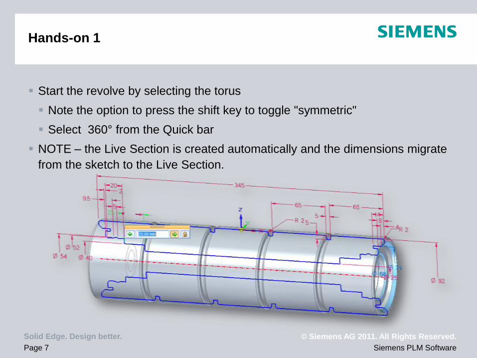
Start the revolve by selecting the torus
Note the option to press the shift key to toggle "symmetric"
Select 360° from the Quick bar
NOTE – the Live Section is created automatically and the dimensions migrate
from the sketch to the Live Section.
© Siemens AG 2011. All Rights Reserved.
Siemens PLM SoftwarePage 8
Solid Edge. Design better.
Hands-on 1
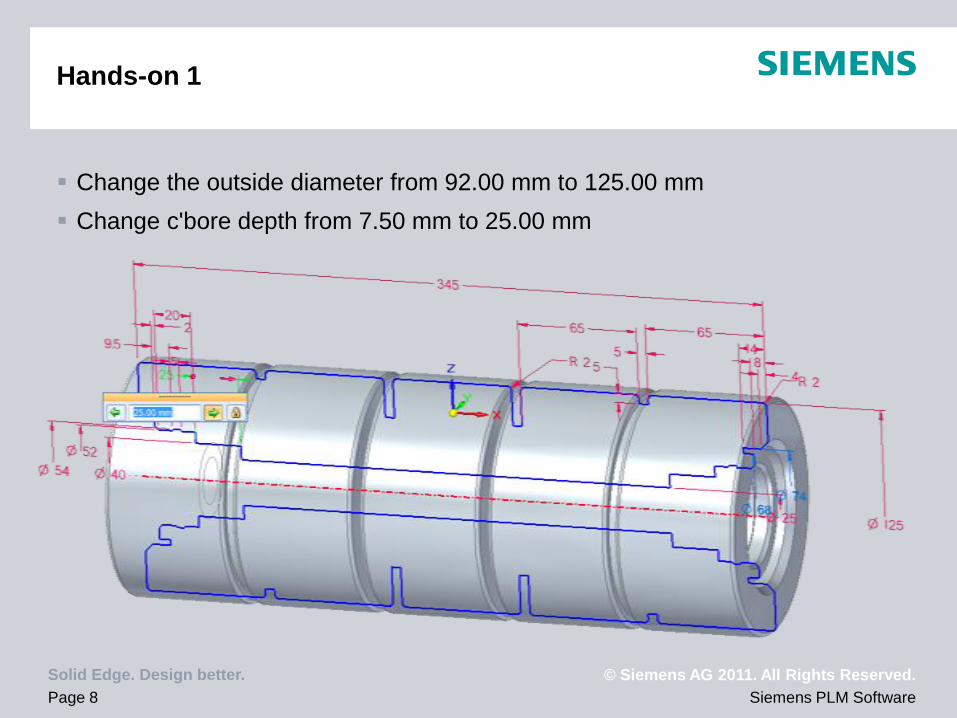
Change the outside diameter from 92.00 mm to 125.00 mm
Change c'bore depth from 7.50 mm to 25.00 mm

© Siemens AG 2011. All Rights Reserved.
Siemens PLM SoftwarePage 9
Solid Edge. Design better.
Hands-on 1
Hide the PMI dimensions and the base coordinate system
Now we want to add a drain hole through the center of the roller.
Start the hole command to create a 10.00 mm, simple, through hole

© Siemens AG 2011. All Rights Reserved.
Siemens PLM SoftwarePage 10
Solid Edge. Design better.
Hands-on 1
Place the cursor over the center cylinder
of the roller and click F3 to locate using
the tangent plane
Note how you can rotate the plane and
can key-in a precise angle
Key in or snap to 90°

© Siemens AG 2011. All Rights Reserved.
Siemens PLM SoftwarePage 11
Solid Edge. Design better.
Hands-on 1
Place the hole on the tangent line and snap to the midpoint of the live section
element
Live section updates with the through hole
DONE – close all open files

© Siemens AG 2011. All Rights Reserved.
Siemens PLM SoftwarePage 12
Solid Edge. Design better.
Hands-on 2
Open ASM_01_00701.asm
Note that in the original design, the brackets are angled and close to causing
interference with the roller.
In-place activate into the sheet metal bracket on the right
The bracket on the left is a linked mirrored copy.

© Siemens AG 2011. All Rights Reserved.
Siemens PLM SoftwarePage 13
Solid Edge. Design better.
Hands-on 2
Select the Horizontal/Vertical Relate command
and select the angled face
Makes this face horizontal/vertical to the base reference planes

© Siemens AG 2011. All Rights Reserved.
Siemens PLM SoftwarePage 14
Solid Edge. Design better.
Hands-on 2
Hide the previous level, the base coordinate
system, and the PMI dimensions
Using the horizontal/vertical relate tool,
center the roller mounting hole with the
edge of the sheet metal bracket

© Siemens AG 2011. All Rights Reserved.
Siemens PLM SoftwarePage 15
Solid Edge. Design better.
Hands-on 2
Select the hole and move it
Note the edge of the part grows with the change due to the persisted
relationship
Move it up 4.00 mm

© Siemens AG 2011. All Rights Reserved.
Siemens PLM SoftwarePage 16
Solid Edge. Design better.
Hands-on 2
Close and return
DONE - Close all files

© Siemens AG 2011. All Rights Reserved.
Siemens PLM SoftwarePage 17
Solid Edge. Design better.
Hands-on 3
Open ASM_01_00006.asm
In-place activate into the
Brown seat part
PAR_04_00122.par

© Siemens AG 2011. All Rights Reserved.
Siemens PLM SoftwarePage 18
Solid Edge. Design better.
Hands-on 3
We need to make the seat wider.
We want to first make this ordered part synchronous to make it wider.
Select the Back cutout angle
Fence select ½ of the seat and stretch 35.00 mm (70 mm wider total)
© Siemens AG 2011. All Rights Reserved.
Siemens PLM SoftwarePage 19
Solid Edge. Design better.
Hands-on 3
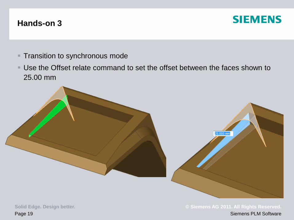
Transition to synchronous mode
Use the Offset relate command to set the offset between the faces shown to
25.00 mm

© Siemens AG 2011. All Rights Reserved.
Siemens PLM SoftwarePage 20
Solid Edge. Design better.
Hands-on 3
Rotate the side face of the seat 2°
© Siemens AG 2011. All Rights Reserved.
Siemens PLM SoftwarePage 21
Solid Edge. Design better.
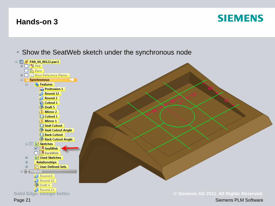
Hands-on 3
Show the SeatWeb sketch under the synchronous node

© Siemens AG 2011. All Rights Reserved.
Siemens PLM SoftwarePage 22
Solid Edge. Design better.
Hands-on 3
Create a web network
Set option to single and fence select the sketch
8.00 mm wide
5° Draft
Hide the sketch

© Siemens AG 2011. All Rights Reserved.
Siemens PLM SoftwarePage 23
Solid Edge. Design better.
Hands-on 3
Add centerline dimensions to the ribs
Distance between dimension
Set the keypoint option to find midpoints

© Siemens AG 2011. All Rights Reserved.
Siemens PLM SoftwarePage 24
Solid Edge. Design better.
Hands-on 3
Move the ribs out from the center by 10 mm using the PMI dimensions
© Siemens AG 2011. All Rights Reserved.
Siemens PLM SoftwarePage 25
Solid Edge. Design better.
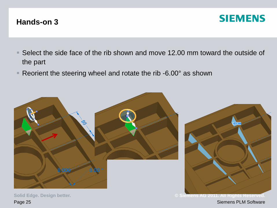
Hands-on 3
Select the side face of the rib shown and move 12.00 mm toward the outside of
the part
Reorient the steering wheel and rotate the rib -6.00° as shown

© Siemens AG 2011. All Rights Reserved.
Siemens PLM SoftwarePage 26
Solid Edge. Design better.
Hands-on 3
Select the side face of the rib shown and move 12.00 mm toward the outside of
the part
Reorient the steering wheel and rotate the rib -6.00° as shown

© Siemens AG 2011. All Rights Reserved.
Siemens PLM SoftwarePage 27
Solid Edge. Design better.
Hands-on 3
Toggle hide previous level to see the background parts
We want to center to cylindrical rib with the sensor switch under the seat.

© Siemens AG 2011. All Rights Reserved.
Siemens PLM SoftwarePage 28
Solid Edge. Design better.
Hands-on 3
Select the inside cylinder and outside cylinder face and use the steering wheel
axis to initiate a move
Pick up the center of the switch as a keypoint to move to

© Siemens AG 2011. All Rights Reserved.
Siemens PLM SoftwarePage 29
Solid Edge. Design better.
Hands-on 3
Add the web network to the back of the seat using the same techniques
Rotation angle of 5°

© Siemens AG 2011. All Rights Reserved.
Siemens PLM SoftwarePage 30
Solid Edge. Design better.
Hands-on 3
Show the background parts
Next we want to create feature matching
feet on the bottom of the seat that will
fit into the rubber shock absorbers.
Run the Extrude command

© Siemens AG 2011. All Rights Reserved.
Siemens PLM SoftwarePage 31
Solid Edge. Design better.
Hands-on 3
Select the 4 faces in the bottom of the pockets in the rubber shock absorbers
Note we did not have to make interpart copies or include edges
Extrude "Through Next" to create the 4 feet

© Siemens AG 2011. All Rights Reserved.
Siemens PLM SoftwarePage 32
Solid Edge. Design better.
Hands-on 3
Drag the end face 12.00 mm to make them shorter
Transition to Ordered and add a 3.00 mm round to the pocket edges

© Siemens AG 2011. All Rights Reserved.
Siemens PLM SoftwarePage 33
Solid Edge. Design better.
Hands-on 3
Close and return to the top level assembly
Mate the foot to the pocket in the rubber shock absorber

© Siemens AG 2011. All Rights Reserved.
Siemens PLM SoftwarePage 34
Solid Edge. Design better.
Hands-on 3
Done!

© Siemens AG 2011. All Rights Reserved.
Siemens PLM SoftwarePage 35
Solid Edge. Design better.
Conclusions
Solid Edge ST4 has enhanced and added new functionality to make using
Solid Edge easier and a more enjoyable experience for everyday users.