Embed Size (px)
Citation preview

}
SODIUS / EADS CASSIDIAN
MD DAY 2010MODEL DRIVEN ARCHITECTURE FOR SUPPORTING SYSTEMS ENGINEERING AT CASSIDIAN
25 November 2010
Yann LEBEAUPIN – SODIUS – CTO
Jean-Baptiste CARTIER – EADS CASSIDIAN - PLM Technical Expert

Agenda
Introduction
Who is SODIUS?
Collaboration with CASSIDIAN (EADS D&S) since 2009
Enterprise Architecture Framework Interchange Solution Definition
Application and Feedback on a tool migration project
IPSE project and System Engineering collaborative software
perspectives
Model driven architecture for supporting systems engineering at Cassidian

Who is Sodius ?
SODIUS, started in 1999
SODIUS is specialized in Systems Engineering and Interoperability
SODIUS is recognized as a leading company to bridge different tools used by engineers involved in systems or software projects.
SODIUS, is a technology provider for IBM, NoMagic, and a certified IBM Business Partner.
SODIUS provides solutions to interoperate with a number of engineering tools : to transform models, to customize code generators, and create Word documentation from multiple models.
We have highly specialized tools and skills for:
• Model-Driven Engineering
• Multidisciplinary Systems Engineering
• Legacy Models handling
• Long Life Cycle handling (>10 years)

Model Integration and Tools Interoperability Projects
Who is Sodius ?
Based on a common Moded-Based approach and
MDWorkbench technology platform and assets

SODIUS &
Since 2009, SODIUS develops for CASSIDIAN (former EADS Defence & Security)
solutions enabling interchange of data between modeling (architecture framework)
tools in the context of System Engineering projects.
These solutions are achieved as part of a common CASSIDIAN corporate effort
named IPSE (Integrated Project Support Environnement) which goal is to provide a
suite of tools for System Engineering.
First phase of project
Communication between tools for data and diagram exchange
Second and subsequent phases :
Implementation of a "bus" to communicate with more advanced features
as configuration management and automation of authoring activities

Introduction
Who is SODIUS?
Collaboration with CASSIDIAN (EADS D&S) since 2009
Enterprise Architecture Framework Interchange Solution Definition
Scope and solution architecture
Application and Feedback on a CASSIDIAN migration project
IPSE project and System Engineering collaborative software perspectives
Model driven architecture for supporting systems engineering at Cassidian
Agenda

Exchange the models
In the real world, a single toolset is not possible…however we need:
Be able to “exchange” models with partners/external customers/subcontractors on a single target even if
teams have different/heterogeneous choices (historical, national, businness)
To re-use “architecture models”, integrate or migrate “legacy” components
Reuse legacy models (as components) and insert them into new designs
…enhance/customize them to support specific features and manage specific value
DBMSTOOL A
DBMSTOOL B
DBMSTOOL C
?Accept the diversity !
Development of complex systems requires dedicate solutions to enable
exchange, reuse or integrate models helping systems engineers to
handle complete scope and challenges of systems architecting and
management throughout the lifecycle of the system

CASSIDIAN Project context
BorderShield Project Legacy
3 Tools currently used on the BorderShield project in DoDAF context
2
DoDAF
Models initially
created and
used on German
CASSIDIAN
project, then on
BorderShield
1
Change authoring ?
How migrate models and diagrams ?
MEGA 2009
Recommended by our
business Unit
3

Drivers for Change
Facts on the Bordershield project
Initial choice : SA as common language – legacy models
Collateral architecture team shift from SA to EA
Bordershield Technical Opportunity to move to another modelling solution ?
MEGA has been selected on technical criteria
Identified in an internal justification table
Mainly○ Cosmetic features
○ Power of the tool itself
DoDAF SV3 views useless on System Architect
Higher consistency check with MEGA, close to the MetaModel
○ Few support on System Architect in the French « community »
Translation from SA to MEGA 2009 decided
and performed in June 2010 by SODIUS and CASSIDIAN teams

Problem statement
The scope of the solution is to provide an
architecture for
Exchanging models and diagrams
Between MEGA and System Architect
Considering future extensibility needs
DoDAF
One thing that is sure: Actors, Tools, Process,Standards (DoDAF, NAF, UPDM, etc…) WILL CHANGE
The challenge is to integrate architectures in 2010 (t)
AND maintain this capability in 2011, 2015,etc… (t+n) !
NAF
The SAM project had to consider
too the underlying movement to
NAF (NATO Architecture
Framework) in the domain of
complex systems of systems
(NATO, Defence actors, LSI
European projects)
General Capability Requirements
Model Exchange should cover the content of DoDAF ,
and later of NAF
Model Exchange should be “vendor neutral”

Proposed Solution
Adopt NAF V3 Metamodel (NMM) as the pivot format for EA models NAF V3 has the largest user support
NAF V3 has almost a complete coverage for System Engineering projects
Adopt UML2 diagrams as the diagram types for NAF NMM is defined as a abstract UML profile using underlying UML concepts
Ensure application connectivity maintenability
Direct tool integration (P2P) should be avoided because:• There are too many tools involved
• Such integration depends on tools internal architectures which are not under control of the
integration platform
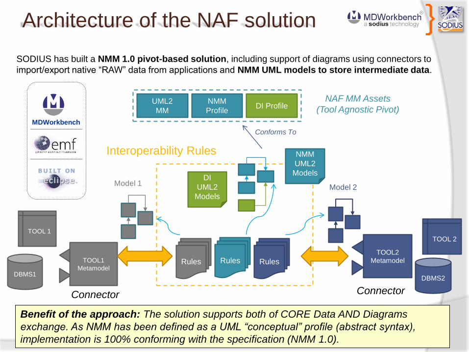
Architecture of the NAF solution
SODIUS has built a NMM 1.0 pivot-based solution, including support of diagrams using connectors to
import/export native “RAW” data from applications and NMM UML models to store intermediate data.
Benefit of the approach: The solution supports both of CORE Data AND Diagrams
exchange. As NMM has been defined as a UML “conceptual” profile (abstract syntax),
implementation is 100% conforming with the specification (NMM 1.0).
NMM
Profile
UML2
MMDI Profile
NAF MM Assets
(Tool Agnostic Pivot)
Conforms To
DBMS1
TOOL 1
TOOL1
Metamodel
TOOL2
Metamodel
DBMS2
TOOL 2
Model 1Model 2
Interoperability Rules
RulesRules
DI
UML2
Models
Rules
NMM
UML2
Models
MDWorkbench
Connector Connector

Interoperability approach
SODIUS’ interoperability approach is based on MDWorkbench platform:
Separated approach between the data (I/O) and the required
transformation : Connectors + MMs + Rules
Metamodels to abstract data model (instead of syntax views)
Connectors to enable tools access (read/write) in multiple, reusable ways and
feed models (conforming to previous MMs)
Rules for specific mapping
Capacity of SODIUS to create new connectors quickly (using any text or xml
formats, apis, web-services or database access)
DBMS1
TOOL 1
RulesTOOL1
Metamodel
Model 1
Benefit of the approach: Rules manage specific exchange process, connectors are
reusable assets encapsulating complexity of connection with tools.
Connector =
MM + Reader
+ Writer
Connectors are
able to manage
many kind of
formats

Diagram Support
SODIUS is involved in the XMI Interchange Workgroup
Even if normalization consensus has not been reached, UML DI Extension referencing UML
semantic elements is a good way to represent “common” denominator between applications in a
pragmatic way
Based on DI format, connectors use diagramming apis or proprietary formats of tools to re-create
diagrams from neutral DI defintions
To manage diagrams in the closest way that target authoring environment allow it, some layout
rules have to be add for each tool (anchors management, edges/nodes support differences
between tools, default shapes) – there is a “human” interpretation to find consensus
(“common denominator”).
DI Profile
NMM
Profile
UML2
MM
NAF MM Assets
“XMI” DI File
DI Model
Semantic
Data
DI Metamodel

Diagram Support“Tool-Agnostic” Viewers of
NAF ModelsDI Model
Connectors use diagramming apis or proprietary
formats serializers to re-create diagrams into
authoring tools from neutral DI definitions

Samples of managed views
MEGA
System
Architect
Diagrams and Data can be exchanged between tools (each time view
concepts are supported by the authoring tool)
UML Base Classes
«metaclass»
InformationFlow
«metaclass»
Property
«metaclass»
Class
wh
ole
1
*
pa
rt
1
*
targ
et
1
*
so
urc
e
1
*
Node
«extends»
NodeAssemblyUsage
InformationExchange
targ
et
1
*
so
urc
e
1
*
cla
ss
1
*
typ
e
1
*
NOV-2 Stereotypes
«metaclass»
Package
1
ownedMember*
ArchitecturalDescription
NodeRelationshipDescription
ArchitecturalProduct
CompositeStructureModel«extends»
«extends»
owningArchitecture1
products*
«metaclass»
PackageableElement
«metaclass»
Dependency
«extends»
«extends»
«extends»
NodeConnector«metaclass»
Connector
«metaclass»
ConnectorEnd
«extends»
1
2
NodeConnectorEnd
«extends»
su
pp
ortin
gN
ee
dlin
es
Needline
NestedConnectorEnd
role
co
nn
ectio
nC
on
text
«metaclass»
StructuredClassifier1
ow
ne
dC
on
ne
cto
r
*
1e
nd
*
rea
lizin
gC
on
ne
cto
r
«metaclass»
Activity
«extends»
OperationalActivity
NodeHasBehavior
co
nd
ucte
dA
t
1
*
activityConducted
1
*
«metaclass»
NamedElement
supplier
1..*
*
client
1..*
*
NAF Metamodel

CASSIDIAN Lesson’s learnt on SAM
Semi-automatic procedure including two stages
MDWorkbench automatic on the full modelling DataBase (100% Data/90% Diagrams)
Some manual modification on geometry and layout of elements
Inputs
Mapping of objects sometimes tricky between SA and MEGA Common work on
Specification Document
Outputs
Quick translation : one week workload on 150 views / 1500 modelling items
○ Some manual fixes
Mainly due to IDEF0 notation origin use in OV05 DoDAF Views, artefacts items to be
corrected
Geometry cf. manual work
Hidden objects Board side effect still to be fixed
Much quicker than modelling from scratch
No lost or wrong migration of modelling objects and diagrams

Cassidian Findings
Was this development successful?
○ Yes, it provides a real benefit for CASSIDIAN, compared to re-modelling
Is the connector bidirectional
○ Yes, the reverse translation (from MEGA to SA) has been tested. It also requires manual re-drawing
What are the possible extensions on the connector:
○ The success of this first attempt has opened the way to NAF model transformation between various tools. As a new feature expected,
integration of Enterprise Architect © would be of interest.
FAQs How do I validate import/export ?
We are able to generate “exchange” reports comparing for each view number of elements between source and target
tools (including type and name sorting)
How diagrams are managed ?
Using common diagram interchange properties, MDWorkbench connectors create diagrams using authoring tool client
apis (MEGA/SA) or native formats of modeler : Position, Size, Color, Font, Visibility are handled.
Is there any limitation ?
According authoring tools, some concepts are missing . In such case, bridge documentation lists unsupported elements
between tools. These differences come from proprietary extensions and not really from AF itself (e.g: capability to mix
NAF + BPMN + UML + Custom xxx in the same tool) – This could be handled by introducing model checking rules earlier
in the design tasks.
Some diagrams are totally different (e.g. Custom Shape vs. Unmodifiable Rectangle Figure, 3D layout vs. 2D layout, IDEF
vs. Activity Diagram, Table vs. Tree views) – In this case 100% of data and diagrams figures is converted but diagrams’
layout has to be manually modified. We work to improve this special cases by improving custom optional “properties” on
writers or layout algorithms.

Introduction
Who is SODIUS?
Collaboration with CASSIDIAN (EADS D&S) since 2009
Enterprise Architecture Framework Interchange Solution Definition
Application and Feedback on a EA tool migration project
IPSE project and System Engineering collaborative software perspectives
Model driven architecture for supporting systems engineering at Cassidian
Agenda

Introduction
The problem:
LSI Projects are more and more complex
High cost / High risk projects
Long life cycle projects
Lot of actors (engineers, suppliers…)
Rapidly changing requirements
The need:
an integrated environment of system engineering
tools throughout the LSI product life cycle:
○ Requirement management
○ Architecture design
○ Change management
○ Integration & Validation

The system engineering spiral
Requirements
Management
Operational and
System Rules Model
engineering
Business Process &
System Evaluation
Requirement refinement
requirement update from
the prototyping experience
Architecture design.
Operational and System Rules
elements will be linked to
requirements
V & V in simulation.
Business Process & System
elements prototyping

Requirements
Management
Operational and System
Rules Model engineering
Business
Process &
System
Evaluation
Traceability & consistency
Stakeholder
Req.
System
Req.
Technical
Req.
DB
Organic View
System View
Operational View
requirementtraceability
requirementtraceability
Stakeholder
Req.
System
Req.
Technical
Req.

The IPSE Added Value – SE Collaboration
IPSE (Integrated Project Support Environment) is a collaborative software environment for system
engineering from Requirement Engineering, Behaviour & Architecture Modelling, Validation through
Process Simulation, Verification with Systems Simulation to Data Management.
Info traceability (from reqsto delivery) + SoS
maintenance
Data re-use (business objects & logic) to avoid re-inventing the wheel
Info flow control (powerful workflow centric approach)
Data coherency maintenance (link project & BMS F1)
System Engineering life-cycle collaboration (shared
repository)SAM
Bordershield IPSE
Connectors

The IPSE framework
Requirements Engineering
DOORS
SoS Architecture Design
SA
Process Simulation
Product development
PLM
Project Management
Configuration Management
SoSArchitecture
DesignMEGA
SoS Architecture
DesignEA
Connector Backbone
MDWorkbench

SODIUS IPSE Components
SODIUS is developing CASSIDIAN integration and automation tooling
for the IPSE framework
MDWorkbench Authoring tool to configuration management client application
MDWorkbench Model Artifacts Web Viewer
Configuration Management Web Server
MEGA CLIENT MDWorkbench DOORS CLIENT
Web services
Configuration Management Web Server
MDWorkbench
Web Client
HTTP

SODIUS IPSE Components
MDWorkbench “Interface Layer” RCP Eclipse Application
Ensuring communication between configuration management and
authoring tools (user workspace or baseline restore,
checkin/checkout operations)
Configuration
ManagementAuthoring Tools
MDWorkbench
“Interface Layer”
M
E
G
A D
O
O
R
S

SODIUS IPSE Components
DB
MDWorkbench
Interface Layer
Authoring Tools
Configuration
Management
Specify, Design, Produce
Requirement/Architecture
MDWorkbench Web Viewer
Inspect/Review
Architecture &
Produce Change
Request
Exported Model “Unit”
Authoring
ModelCheckin

Questions

Contact
http://www.mdworkbench.com
Paris
1 Rue André Gide
75015 Paris
France
Tel. : +33 (0)1 43 21 16 12
Fax : +33 (0)2.28.23.60.57
Nantes
2 impasse Joseph Marie Fourage
44300 NANTES
France
Tel. : +33 (0)2.28.23.60.60
Fax : +33 (0)2.28.23.60.57
Yann LEBEAUPIN – SODIUS – CTO – [email protected]